Embed Size (px)
Citation preview
201
Electromagnetic Forming and Joining for Automotive Applications S. Golovashchenko1
1 Manufacturing & Processes Department, Ford Research & Advanced Engineering, Dearborn, USA
Abstract
In this paper some options of how electromagnetic forming (EMF) can assist to expand the capabilities of conventional forming and joining technologies are discussed. Three different areas where EMF has the potential for a significant expansion of capabilities of traditional technologies are reviewed: 1) restrike operation to fill sharp corners of automotive panels; 2) low energy method of springback calibration; 3) joining of closed frames with an openable coil. Each of these applications was demonstrated in laboratory conditions and the description of the tooling is provided in the paper. Suggested design of a flat concentrator collecting induced electric currents from a flat coil was demonstrated for a corner filling operation and a springback calibration. An efficient technique of fabricating the flat coil from a flat plate by using water jetting technology enables a cost effective coil design, which can be reinforced by a system of non-conductive bars. The insulation of the coil is produced from the flat sheet of insulation material. Suggested design allows the coil to be repaired if a shortcut or fracture of insulation strips happens. A technology of low-energy calibration of stamped parts provides an option of working with a wider variety of materials including aluminum alloys, mild steels, and advanced high-strength steels. This technology is demonstrated for calibration of U-channels.
Keywords:
Forming, Joining, Tooling, Springback
1 Introduction
In pulsed electromagnetic forming and joining a coil can be described as a tooling replacing a punch in conventional forming operations. Depending upon the coil configuration, various stamping processes can be carried out, such as tube expansion, tube compression, and flat sheet forming [1]. However, due to a number of issues including coil durability, maximum stamping rate, safety implications etc., electromagnetic stamping technologies have not been able to compete with conventional stamping on the
Magpulse Technologies
1
2nd International Conference on High Speed Forming – 2006
202
press if conventional processes provided the desired result. Therefore, our strategy is to use electromagnetic forming (EMF) to expand the capabilities of conventional forming and joining technologies. In this paper, we will discuss three different areas where EMF has the potential for a significant expansion of capabilities of traditional technologies: 1) restrike operation to fill sharp corners of automotive panels; 2) low energy method of springback calibration; 3) joining of closed frames with an openable coil.
2 Restrike operation of parts preformed using conventional stamping technology
Due to the tendency that electromagnetic pressure is usually rapidly decreasing as soon as the blank moves away from the coil, deep drawing operations are not feasible for EMF unless some special arrangements are made to move the coil close to an already deformed blank. Another option is to use several steps of EMF with coil configuration at the following step, corresponding to the blank shape after the previous step. This approach may be acceptable for low-volume production. However, for high-volume production it may not be appropriate. More attractive is the combination of conventional forming and EMF when EMF is applied as a restrike operation for difficult-to-form areas. It has been proven experimentally [2] that for corner filling operations EMF can produce a significant improvement in formability due to a number of effects described in [3], including high strain rate, bending-unbending, significant hydrostatic pressure, and coining effect. Some complications of EMF employment for restrike operations are dictated by limited space for the coil. Typically, to have a high-efficiency EMF process, the ratio of the inductance of the coil with blank related to the total inductance of the EMF machine-coil-blank system should be approximately 0.8…0.9 [1]:
(1)
In other words, the inductance of the coil should dominate over the inductance of the EMF machine and its connection to the coil. To satisfy this requirement, the coil should have multiple turns since the inductance of the coil can be described in a following way
(2) where n is the number of turns in the coil. Multiple turns are difficult to accommodate in limited space for restrike operations and also may not be feasible from the coil strength and durability point of view. Evidently, the cross-section of the turn dictates its stiffness against torsion moments developed as a result of interaction of adjacent turns of the coil and also due to the skin effect. Usage of a single turn coil usually leads to low efficiency of the process. The suggested solution is in a system including a flat coil and a concentrator [4], combining high efficiency of the multi turn coil and structural strength of a single-turn coil. The schematic of the discussed coil system is shown in Figure 1. The important feature of the flat coil is that its spiral is relatively easy to fabricate: the spiral can be manufactured from a flat plate [5] using water jetting technology, which provides a significant cost reduction compared to end milling technology. Compared to a winding
.9.0...8.01 ≈++
=+
+
blankcoilconnectionmach
blankcoil
LLLLK
,~ 2nL blankcoil+
Magpulse Technologies
2
2nd International Conference on High Speed Forming – 2006
203
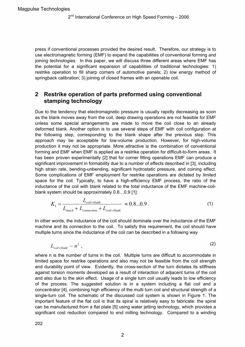
technique, the water jetting technology provides a more accurate shape of the surface and allows maintaining a uniform and rather small clearance between the coil and the blank since during the winding procedure an originally straight bar gets curved as a result of plastic bending, producing distortion of the original cross-section. Also, in the suggested new design the coil should be reinforced to balance significant forces in between the turns of the coil. This can be accomplished by employing non-conductive rods, as it is indicated in Figure 2. An expansion of the coil can be prevented by putting the coil into a metallic bandage [5].
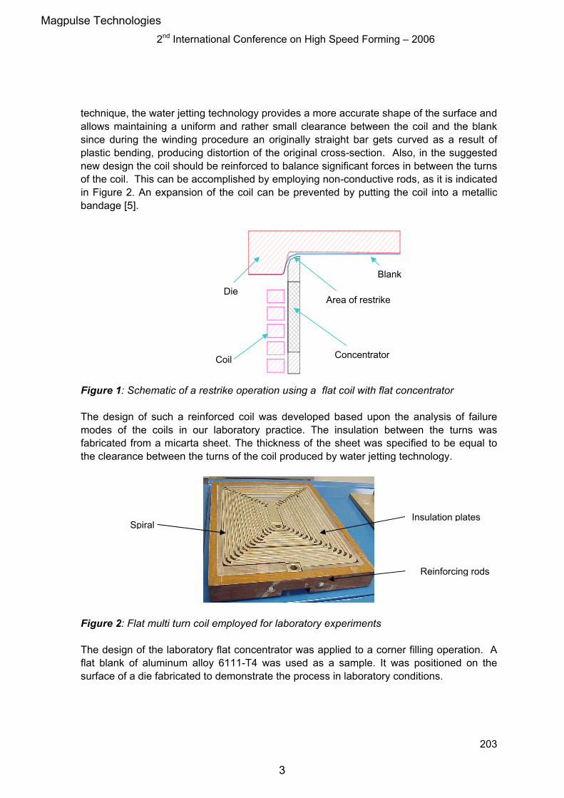
Figure 1: Schematic of a restrike operation using a flat coil with flat concentrator The design of such a reinforced coil was developed based upon the analysis of failure modes of the coils in our laboratory practice. The insulation between the turns was fabricated from a micarta sheet. The thickness of the sheet was specified to be equal to the clearance between the turns of the coil produced by water jetting technology.
Figure 2: Flat multi turn coil employed for laboratory experiments The design of the laboratory flat concentrator was applied to a corner filling operation. A flat blank of aluminum alloy 6111-T4 was used as a sample. It was positioned on the surface of a die fabricated to demonstrate the process in laboratory conditions.
Spiral Insulation plates
Reinforcing rods
Die Area of restrike
Blank
Concentrator Coil
Magpulse Technologies
3
2nd International Conference on High Speed Forming – 2006
204
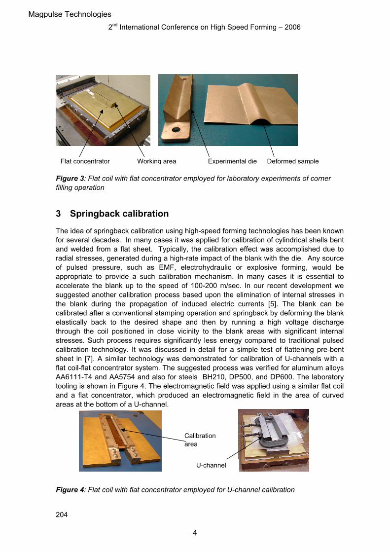
Figure 3: Flat coil with flat concentrator employed for laboratory experiments of corner filling operation
3 Springback calibration
The idea of springback calibration using high-speed forming technologies has been known for several decades. In many cases it was applied for calibration of cylindrical shells bent and welded from a flat sheet. Typically, the calibration effect was accomplished due to radial stresses, generated during a high-rate impact of the blank with the die. Any source of pulsed pressure, such as EMF, electrohydraulic or explosive forming, would be appropriate to provide a such calibration mechanism. In many cases it is essential to accelerate the blank up to the speed of 100-200 m/sec. In our recent development we suggested another calibration process based upon the elimination of internal stresses in the blank during the propagation of induced electric currents [5]. The blank can be calibrated after a conventional stamping operation and springback by deforming the blank elastically back to the desired shape and then by running a high voltage discharge through the coil positioned in close vicinity to the blank areas with significant internal stresses. Such process requires significantly less energy compared to traditional pulsed calibration technology. It was discussed in detail for a simple test of flattening pre-bent sheet in [7]. A similar technology was demonstrated for calibration of U-channels with a flat coil-flat concentrator system. The suggested process was verified for aluminum alloys AA6111-T4 and AA5754 and also for steels BH210, DP500, and DP600. The laboratory tooling is shown in Figure 4. The electromagnetic field was applied using a similar flat coil and a flat concentrator, which produced an electromagnetic field in the area of curved areas at the bottom of a U-channel.
Figure 4: Flat coil with flat concentrator employed for U-channel calibration
Flat concentrator Working area Experimental die Deformed sample
Calibration area
U-channel
Magpulse Technologies
4
2nd International Conference on High Speed Forming – 2006
205
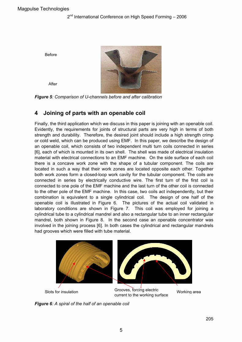
Figure 5: Comparison of U-channels before and after calibration
4 Joining of parts with an openable coil
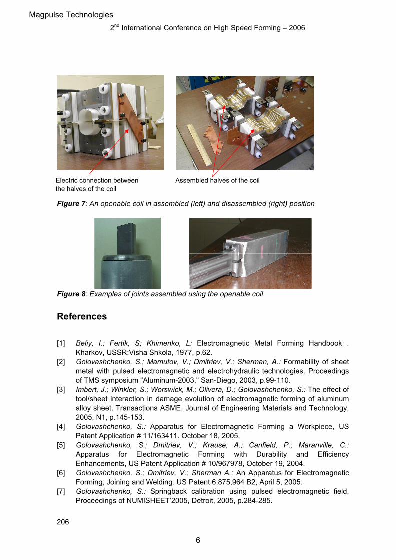
Finally, the third application which we discuss in this paper is joining with an openable coil. Evidently, the requirements for joints of structural parts are very high in terms of both strength and durability. Therefore, the desired joint should include a high strength crimp or cold weld, which can be produced using EMF. In this paper, we describe the design of an openable coil, which consists of two independent multi turn coils connected in series [6], each of which is mounted in its own shell. The shell was made of electrical insulation material with electrical connections to an EMF machine. On the side surface of each coil there is a concave work zone with the shape of a tubular component. The coils are located in such a way that their work zones are located opposite each other. Together both work zones form a closed-loop work cavity for the tubular component. The coils are connected in series by electrically conductive wire. The first turn of the first coil is connected to one pole of the EMF machine and the last turn of the other coil is connected to the other pole of the EMF machine. In this case, two coils act independently, but their combination is equivalent to a single cylindrical coil. The design of one half of the openable coil is illustrated in Figure 6. The pictures of the actual coil validated in laboratory conditions are shown in Figure 7. This coil was employed for joining a cylindrical tube to a cylindrical mandrel and also a rectangular tube to an inner rectangular mandrel, both shown in Figure 8. In the second case an openable concentrator was involved in the joining process [6]. In both cases the cylindrical and rectangular mandrels had grooves which were filled with tube material.
Figure 6: A spiral of the half of an openable coil
Before
After
Working areaGrooves, forcing electric current to the working surface
Slots for insulation
Magpulse Technologies
5
2nd International Conference on High Speed Forming – 2006
206
Figure 7: An openable coil in assembled (left) and disassembled (right) position
Figure 8: Examples of joints assembled using the openable coil
References
[1] Beliy, I.; Fertik, S; Khimenko, L: Electromagnetic Metal Forming Handbook .
Kharkov, USSR:Visha Shkola, 1977, p.62. [2] Golovashchenko, S.; Mamutov, V.; Dmitriev, V.; Sherman, A.: Formability of sheet
metal with pulsed electromagnetic and electrohydraulic technologies. Proceedings of TMS symposium "Aluminum-2003," San-Diego, 2003, p.99-110.
[3] Imbert, J.; Winkler, S.; Worswick, M.; Olivera, D.; Golovashchenko, S.: The effect of tool/sheet interaction in damage evolution of electromagnetic forming of aluminum alloy sheet. Transactions ASME. Journal of Engineering Materials and Technology, 2005, N1, p.145-153.
[4] Golovashchenko, S.: Apparatus for Electromagnetic Forming a Workpiece, US Patent Application # 11/163411. October 18, 2005.
[5] Golovashchenko, S.; Dmitriev, V.; Krause, A.; Canfield, P.; Maranville, C.: Apparatus for Electromagnetic Forming with Durability and Efficiency Enhancements, US Patent Application # 10/967978, October 19, 2004.
[6] Golovashchenko, S.; Dmitriev, V.; Sherman A.: An Apparatus for Electromagnetic Forming, Joining and Welding. US Patent 6,875,964 B2, April 5, 2005.
[7] Golovashchenko, S.: Springback calibration using pulsed electromagnetic field, Proceedings of NUMISHEET’2005, Detroit, 2005, p.284-285.
Assembled halves of the coilElectric connection between the halves of the coil
Magpulse Technologies
6