Embed Size (px)
Citation preview
Multilayer Graphene Rubber
Nanocomposites
Inaugural-Dissertation
to obtain the academic degree
Doctor rerum naturalium (Dr. rer. nat.)
submitted to the Department of Biology, Chemistry and Pharmacy
of Freie Universität Berlin
by
DANIELE FRASCA
from Colleferro (IT)
2016
This PhD-Thesis was conducted from January 2013 to April 2016 at the Bundesanstalt für
Materialforschung und -prüfung (BAM) (Berlin) under the supervision of Priv.- Doz. Dr. rer.
nat. habil. Bernhard Schartel.
1st Reviewer: Priv.-Doz. Dr. rer. nat. habil. Bernhard Schartel, Bundesanstalt für
Materialforschung und -prüfung (BAM) (Berlin).
2nd Reviewer: Prof. Dr. rer. nat. Rainer Haag, Freie Universität Berlin.
Date of Defense: 12.09.2016

to Silvia
“Su coraggio, chi ha una spada la affili”
Stefano Benni

Acknowledgements
First of all I would like to thanks Priv.-Doz. Dr. rer. nat. habil. Bernhard Schartel for
giving me this great opportunity to conduct my PhD research in his group. He always
supports me and gives me scientific suggestions to fulfill my PhD work.
I also thank Prof. Dr. rer. nat. Rainer Haag for reviewing this work.
Naturally I have to thank several others people of the division 7.5 of the BAM: the
“Gummi Team” (Dietmar, Carsten, Bernd and Jeannette), Dr. rer. nat. Böhning, Dr. rer. nat.
Wachtendorf, Thommy, Patrick and the guys of the workshop.
I cannot forget my “Travel Fellowship” led by Michael and Sebastian, and including:
Analice, Benjamin, Sebastian, Nora, Karoline, Marie-Claire (Loulou), Marie-Bernadette,
Antje, Kirsten, Huajie, Patrick, Andreas, Alexander, Tim, Lars, Angelo, Salvatore, Elizabeth,
Yuttapong and Weronika.
A special thanks to my wonderful officemates Aleksandra, Bettina and Melissa.
I want to thank my formal collegues of the “Marangoni”, Massimo, Sabrina, Antonio,
Antonio, Stefano, Paolo, Gaetano, Angelo and Fabio.
My parents and my family were geographically far away but anyway close to me like
my brother, his partner Franziska and their kids (Fabio and Caterina), and my girlfriend Anna.
Now it is time to thank all my Italian friends, starting with the “Shit Friends”
(Jackone, il Maestro, la Bestia di Seitan, Gommo, Riccardone, Lord e Amedeo), the guys of
the “FantaPerMnganese” and “FantaQuessi”, my old friends of Colleferro (Emanuele, Yuri,
Ciccio, Francesco, Emanuele, Riccardo, Michela, Michela, Silvia and Eleonora) and my dear
University colleagues (Augusto, Roberto, Matteo, Daniela, Paola, Carmela, Marialuisa,
Barbara e Federica).

In the end I would like the thanks my “Culopesantici” friends in Berlin and moreover
Andrea, Marco, Mattia, Lorenzo, Veronica, Carolina, Oana and Martina fantastic people that
enjoyed with me the life in Beerlin.
Table of Contents
1. Introduction 1
1.1 General Aspect of Rubbers 1
1.2 Rubber Composites 4
1.2.1 Preparation of Rubber Composites 6
1.3 Rubber Nanocomposites 8
1.3.1 Preparation of Rubber Nanocomposites 16
2. Scientific Goal 19
3. Publications and Manuscripts 22
3.1 Multilayer Graphene / Chlorine-Isoprene-Isobutyl Rubber
Nanocomposites: The Effect of Dispersion
22
3.2 Multilayer Graphene (MLG) Chlorine Isobutyl Isoprene Rubber
Nanocomposites: Influence of the MLG-Concentration on Physical
and Flame Retardant Properties
33
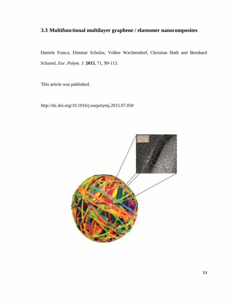
3.3 Multifunctional multilayer graphene / elastomer nanocomposites 53
3.4 Multilayer Graphene/Carbon Black/Chlorine Isobutyl Isoprene
Rubber Nanocomposites
70
4. Summary and Outlook 89
5. Zusammenfassung 91
6. References 94
Abbreviations
BET Brunauer Emmet Teller
CB Carbon Black
CIIR Chlorine Isoprene Isobutyl Rubber
CNT Carbon Nanotubes
CR Polychloroprene
CVD Chemical Vapor Deposition
EHC Effective Heat of Combustion
EG Expanded Graphite
EPDM Ethylene Propylene Rubber
G’ Storage Modulus
GO Graphene Oxide
HRR Heat Release Rate
IIR Isoprene Isobutyl Rubber
LS Layered Silicate
MAHRE Maximum Average of Heat Emission
MBTS Mercaptobenzthiazole Disulfide
MH Maximum of the Torque
ML Minimum of the Torque
MLG Multilayer Graphene
MMT Montmorillonite
MWCNT Multiwall Carbon Nanotubes
NBR Nitrile Butadiene Rubber
NR Natural Rubber
phr Part per Hundred Rubber
PHRR Peak of Release Rate
SBR Styrene Butadiene Rubber
SEM Scanning Electron Microscopy
SWCNT Singlewall Carbon Nanotubes
t100 Time corresponding to 100 % of the
Curing
t90 Time corresponding to 90 % of the
Curing
THE Total Heat Evolved
TEM Thermal Electron Microscopy
Tg Glass Transition Temperature
tig Time of Ignition
ts1 Scortch Time
ΔS Difference between Maximum and
Minimum of the Torque
η' Dynamic Viscosity
1
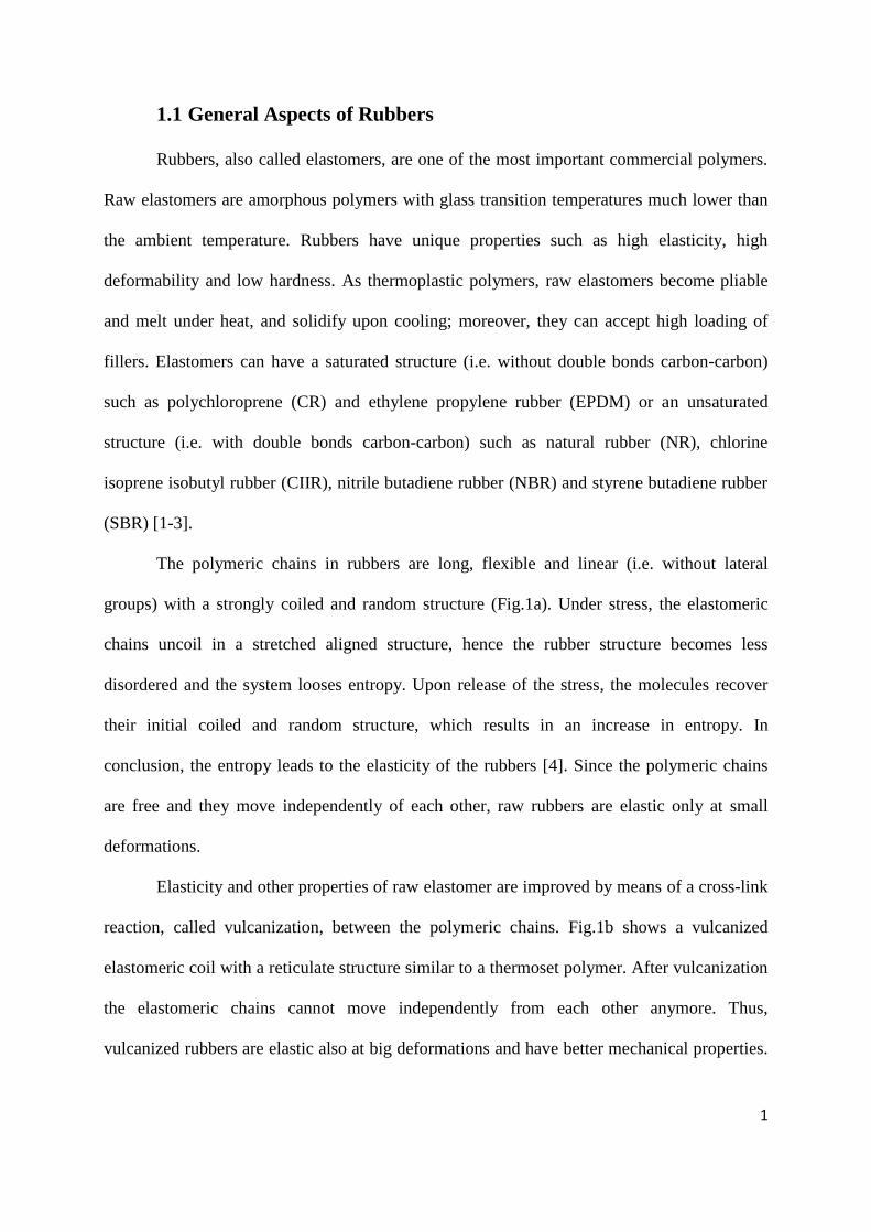
1.1 General Aspects of Rubbers
Rubbers, also called elastomers, are one of the most important commercial polymers.
Raw elastomers are amorphous polymers with glass transition temperatures much lower than
the ambient temperature. Rubbers have unique properties such as high elasticity, high
deformability and low hardness. As thermoplastic polymers, raw elastomers become pliable
and melt under heat, and solidify upon cooling; moreover, they can accept high loading of
fillers. Elastomers can have a saturated structure (i.e. without double bonds carbon-carbon)
such as polychloroprene (CR) and ethylene propylene rubber (EPDM) or an unsaturated
structure (i.e. with double bonds carbon-carbon) such as natural rubber (NR), chlorine
isoprene isobutyl rubber (CIIR), nitrile butadiene rubber (NBR) and styrene butadiene rubber
(SBR) [1-3].
The polymeric chains in rubbers are long, flexible and linear (i.e. without lateral
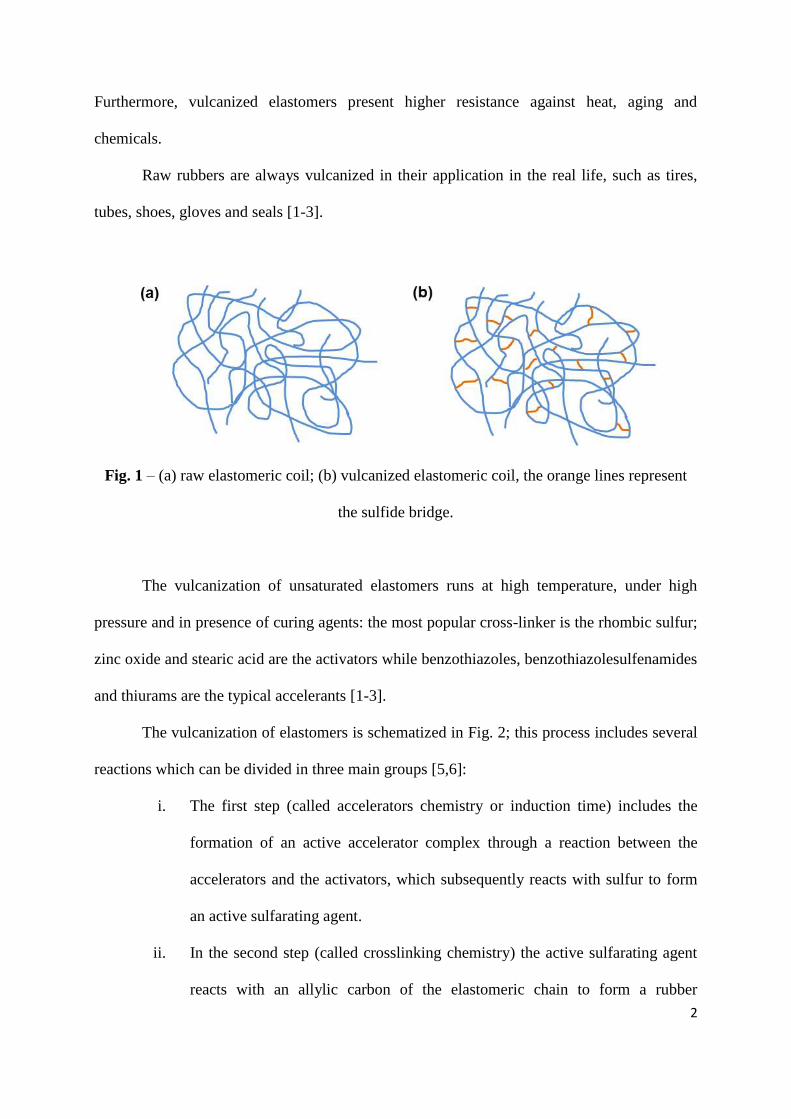
groups) with a strongly coiled and random structure (Fig.1a). Under stress, the elastomeric
chains uncoil in a stretched aligned structure, hence the rubber structure becomes less
disordered and the system looses entropy. Upon release of the stress, the molecules recover
their initial coiled and random structure, which results in an increase in entropy. In
conclusion, the entropy leads to the elasticity of the rubbers [4]. Since the polymeric chains
are free and they move independently of each other, raw rubbers are elastic only at small
deformations.
Elasticity and other properties of raw elastomer are improved by means of a cross-link
reaction, called vulcanization, between the polymeric chains. Fig.1b shows a vulcanized
elastomeric coil with a reticulate structure similar to a thermoset polymer. After vulcanization
the elastomeric chains cannot move independently from each other anymore. Thus,
vulcanized rubbers are elastic also at big deformations and have better mechanical properties.
2
Furthermore, vulcanized elastomers present higher resistance against heat, aging and
chemicals.
Raw rubbers are always vulcanized in their application in the real life, such as tires,
tubes, shoes, gloves and seals [1-3].
Fig. 1 – (a) raw elastomeric coil; (b) vulcanized elastomeric coil, the orange lines represent
the sulfide bridge.
The vulcanization of unsaturated elastomers runs at high temperature, under high
pressure and in presence of curing agents: the most popular cross-linker is the rhombic sulfur;
zinc oxide and stearic acid are the activators while benzothiazoles, benzothiazolesulfenamides
and thiurams are the typical accelerants [1-3].
The vulcanization of elastomers is schematized in Fig. 2; this process includes several
reactions which can be divided in three main groups [5,6]:
i. The first step (called accelerators chemistry or induction time) includes the
formation of an active accelerator complex through a reaction between the
accelerators and the activators, which subsequently reacts with sulfur to form
an active sulfarating agent.
ii. In the second step (called crosslinking chemistry) the active sulfarating agent
reacts with an allylic carbon of the elastomeric chain to form a rubber
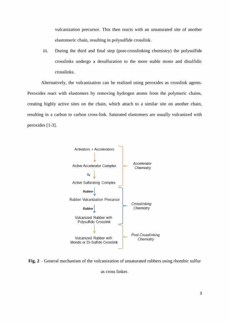
3
vulcanization precursor. This then reacts with an unsaturated site of another
elastomeric chain, resulting in polysulfide crosslink.
iii. During the third and final step (post-crosslinking chemistry) the polysulfide
crosslinks undergo a desulfuration to the more stable mono and disulfidic
crosslinks.
Alternatively, the vulcanization can be realized using peroxides as crosslink agents.
Peroxides react with elastomers by removing hydrogen atoms from the polymeric chains,
creating highly active sites on the chain, which attach to a similar site on another chain,
resulting in a carbon to carbon cross-link. Saturated elastomers are usually vulcanized with
peroxides [1-3].
Fig. 2 – General mechanism of the vulcanization of unsaturated rubbers using rhombic sulfur
as cross linker.
4
1.2 Rubber Composites
In all their applications, rubbers are filled and reinforced with high concentrations
(above 40 phr) of small and hard particles in order to improve the mechanical properties such
as hardness, elastic modulus and abrasion resistance, and functional properties such as gas
barrier, electrical and thermal conductivity [7,8]. Several factors play a role in the reinforcing
of elastomers: the geometrical characteristics of the filler (such as size and aspect ratio), the
intrinsic properties of the filler (such as elastic modulus and electrical conductivity), the
interactions between rubber and filler, the orientation, the dispersion and the concentration of
the filler in the elastomeric matrix [9].
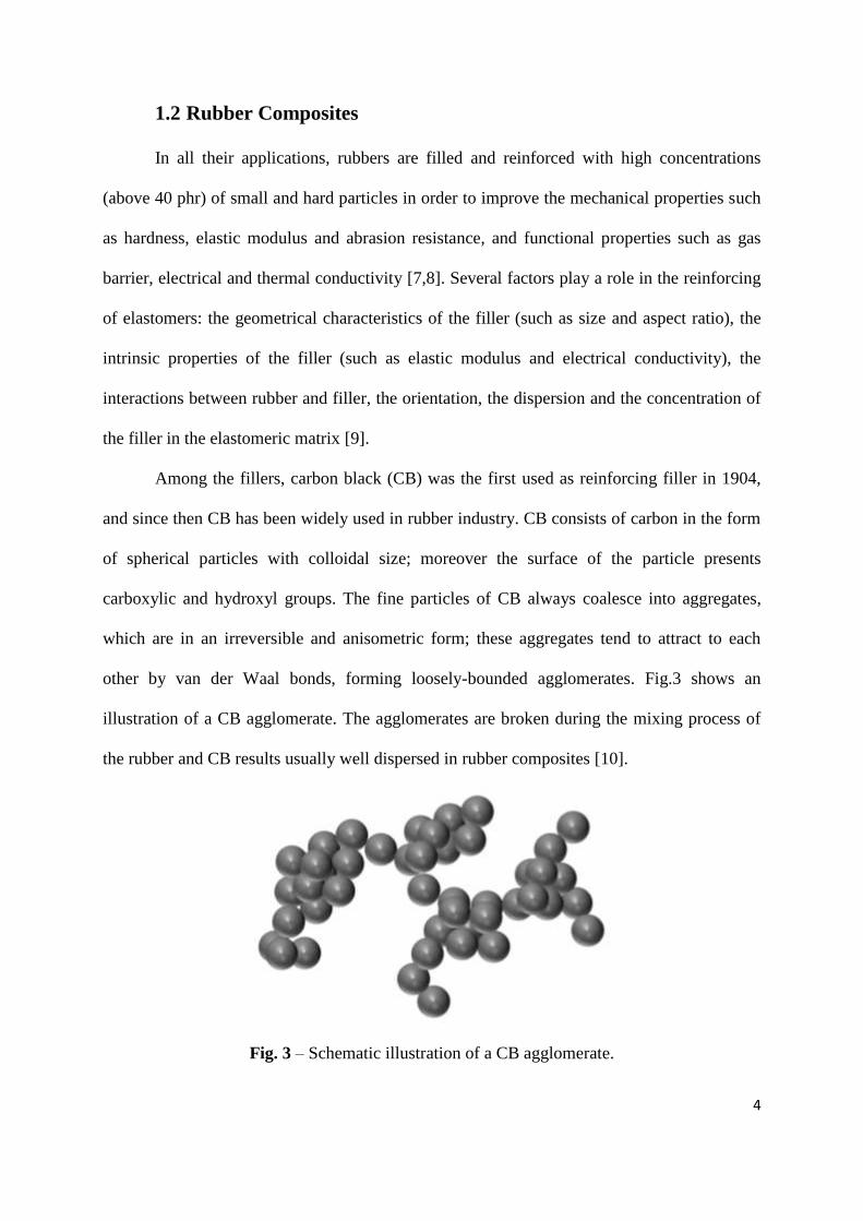
Among the fillers, carbon black (CB) was the first used as reinforcing filler in 1904,
and since then CB has been widely used in rubber industry. CB consists of carbon in the form
of spherical particles with colloidal size; moreover the surface of the particle presents
carboxylic and hydroxyl groups. The fine particles of CB always coalesce into aggregates,
which are in an irreversible and anisometric form; these aggregates tend to attract to each
other by van der Waal bonds, forming loosely-bounded agglomerates. Fig.3 shows an
illustration of a CB agglomerate. The agglomerates are broken during the mixing process of
the rubber and CB results usually well dispersed in rubber composites [10].
Fig. 3 – Schematic illustration of a CB agglomerate.
5
CB is produced by partial combustion or thermal cracking of heavy petroleum
products (furnace black) or natural gas (thermal black). A production reactor consists of two
zones: high temperature zone, to break the hydrocarbons produced by fuel, and quenching
zone, to stop the reaction by adding water. The reaction time is controlled by quenching,
which determines the morphology of the products. Small-size CB is produced by short
reaction time at high temperature [1,3].
Since the 50s, precipitated silica has been used as a filler for rubber. It is an
amorphous form of silicon dioxide produced by reacting sodium silicate solution with either
sulfuric acid. Silica consists of silicon and oxygen arranged in a tetrahedral structure of three-
dimensional lattice. Silica particles present a spherical shape and on their surface there are
several silanol groups which form hydrogen bonds to each other, hence very strong filler-filler
interactions. Thus, the particles of silica always form aggregates and successively
agglomerates[1,3].
Because of its polar nature and the strong filler-filler interactions, the dispersion of
silica in rubbers is very poor. It is usually improved by a surface modification, through the
introduction of appropriate functional groups by chemical reactions. The tetrasulfide-silane is
widely used for the modification of silica in rubber compounds because they are compatible
with the chemical nature of both the filler and the elastomeric matrix. The alkoxy groups of
the silane react with the silanol groups of the silica particles, improving the compatibility
between rubber and silica, and hence the dispersion of the filler, whereas the polysulfide
groups react with the elastomeric chain during the vulcanization process [1,3,11]. The
reaction between silica, tetrasulfide-silane and rubber is illustrated in fig. 4.
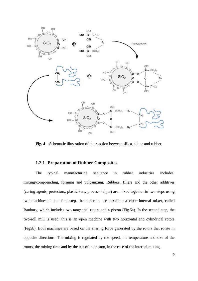
6
Fig. 4 – Schematic illustration of the reaction between silica, silane and rubber.
1.2.1 Preparation of Rubber Composites
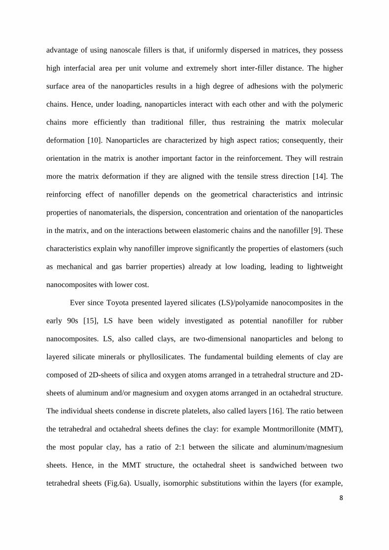
The typical manufacturing sequence in rubber industries includes:
mixing/compounding, forming and vulcanizing. Rubbers, fillers and the other additives
(curing agents, protectors, plasticizers, process helper) are mixed together in two steps using
two machines. In the first step, the materials are mixed in a close internal mixer, called
Banbury, which includes two tangential rotors and a piston (Fig.5a). In the second step, the
two-roll mill is used: this is an open machine with two horizontal and cylindrical rotors
(Fig5b). Both machines are based on the sharing force generated by the rotors that rotate in
opposite directions. The mixing is regulated by the speed, the temperature and size of the
rotors, the mixing time and by the use of the piston, in the case of the internal mixing.

7
Fig. 5 – Schematic illustration of (a) internal mixer and (b) two-roll mill.
After mixing the compounded rubber becomes plastic and ready to be formed in an
appropriate shape for the following vulcanization. In rubber industries screw-type extruders
are used for this operation. For example, the extruder screw forces the rubber through a pair
of rolls to form a slab or a sheet. Otherwise, the rubber compound can be used to coat textiles
or steel cords in a calender. After the rubber compound has been processed and formed, it is
vulcanized. In the most popular vulcanization method, the rubber compounds are cured at
high temperature and pressure in a suitable mold. Other methods include heated dry air
vulcanization and microwave vulcanization [1,3,12].
1.3 Rubber Nanocomposites
In recent years, researchers both in industry and universities have focused their interest
on polymeric nanocomposites, which represent a radical alternative to conventional filled
polymers [13]. In contrast to the conventional system, the reinforcement particles in the
nanocomposites have at least one dimension in the nanometer size range (1-100 nm). The
8
advantage of using nanoscale fillers is that, if uniformly dispersed in matrices, they possess
high interfacial area per unit volume and extremely short inter-filler distance. The higher
surface area of the nanoparticles results in a high degree of adhesions with the polymeric
chains. Hence, under loading, nanoparticles interact with each other and with the polymeric
chains more efficiently than traditional filler, thus restraining the matrix molecular
deformation [10]. Nanoparticles are characterized by high aspect ratios; consequently, their
orientation in the matrix is another important factor in the reinforcement. They will restrain
more the matrix deformation if they are aligned with the tensile stress direction [14]. The
reinforcing effect of nanofiller depends on the geometrical characteristics and intrinsic
properties of nanomaterials, the dispersion, concentration and orientation of the nanoparticles
in the matrix, and on the interactions between elastomeric chains and the nanofiller [9]. These
characteristics explain why nanofiller improve significantly the properties of elastomers (such
as mechanical and gas barrier properties) already at low loading, leading to lightweight
nanocomposites with lower cost.
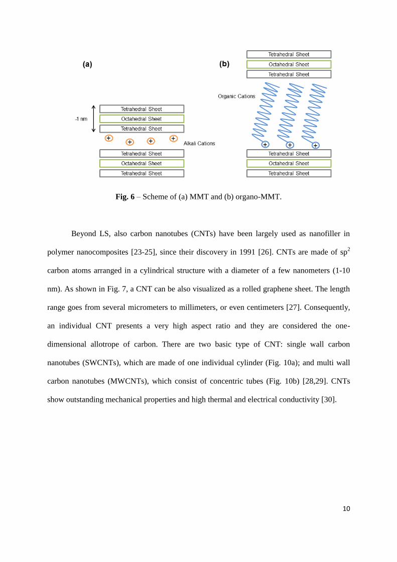
Ever since Toyota presented layered silicates (LS)/polyamide nanocomposites in the
early 90s [15], LS have been widely investigated as potential nanofiller for rubber
nanocomposites. LS, also called clays, are two-dimensional nanoparticles and belong to
layered silicate minerals or phyllosilicates. The fundamental building elements of clay are
composed of 2D-sheets of silica and oxygen atoms arranged in a tetrahedral structure and 2D-
sheets of aluminum and/or magnesium and oxygen atoms arranged in an octahedral structure.
The individual sheets condense in discrete platelets, also called layers [16]. The ratio between
the tetrahedral and octahedral sheets defines the clay: for example Montmorillonite (MMT),
the most popular clay, has a ratio of 2:1 between the silicate and aluminum/magnesium
sheets. Hence, in the MMT structure, the octahedral sheet is sandwiched between two
tetrahedral sheets (Fig.6a). Usually, isomorphic substitutions within the layers (for example,
9
Al3+
replaced by Mg2+
, or Mg2+
replaced by Li+) generate negative charges that are balanced
by alkali cations. Thus, cations are situated in the interlayer space [17]. Each layer has a
thickness of about 1 nm and a width from 30 nm to several μm; hence, a single layer present a
high aspect ratio [18]. Usually, the layers arrange themselves into big stacks due to the Van
der Walls force.
Naturally, the dispersion of inorganic nanofiller in an organic matrix like rubber is
very difficult. This problem can be solved by modifying the interlayer space. When organic
cations are added to water-clay dispersion, the alkali cations are replaced by long organic
chain with positive charge [19-21]. Thus, the LS becomes more compatible with elastomeric
matrix. Usually, alkyl ammonium ions are used to modify LS; they present the following
basic formulas: [R-NH3+], [R2-NH2
+], [R3-NH1
+] and [R4-N
+]. The exchange of ions in the
clay structure results also in the expansion of the interlayer distance (Fig. 6b). These modified
clays are called organoclay [16].
Layered double hydroxides are positive charged LS; the interlayer space of LDHs
contains exchangeable anions. Thus LDHs are also known as anionic clays. Their structure is
very similar to the mineral brucite (Mg(OH)2), in which each Mg2+
is octahedrally surrounded
by six OH-. The octahedrons share their edges to form a two-dimensional layer. The partial
replacement of Mg2+
by trivalent cations results in the positive charged interlayer space.
LDHs can be modified by organic anions (such as dodecyl sulfate), in order to be more easily
dispersed in the polymers. Consequently, this anionic substitution results in an increase of the
interlayer space [22].
10
Fig. 6 – Scheme of (a) MMT and (b) organo-MMT.
Beyond LS, also carbon nanotubes (CNTs) have been largely used as nanofiller in
polymer nanocomposites [23-25], since their discovery in 1991 [26]. CNTs are made of sp2
carbon atoms arranged in a cylindrical structure with a diameter of a few nanometers (1-10
nm). As shown in Fig. 7, a CNT can be also visualized as a rolled graphene sheet. The length
range goes from several micrometers to millimeters, or even centimeters [27]. Consequently,
an individual CNT presents a very high aspect ratio and they are considered the one-
dimensional allotrope of carbon. There are two basic type of CNT: single wall carbon
nanotubes (SWCNTs), which are made of one individual cylinder (Fig. 10a); and multi wall
carbon nanotubes (MWCNTs), which consist of concentric tubes (Fig. 10b) [28,29]. CNTs
show outstanding mechanical properties and high thermal and electrical conductivity [30].

11
Fig. 7 – Representation of (a) SWCNT and (b) MWCNT.
CNTs are mainly synthetized with three different methods: arc-discharge, laser
ablation, and catalytic vapor deposition (CCVD). In the arc discharge method, a current (50-
100 A) is passed through two graphitic electrodes in an inert atmosphere and carbon atoms are
vaporized from the positive electrode (anode) and deposited on the negative electrode
(cathode). The deposit on the cathode contains CNTs and other carbons material, and because
of this a further purification is necessary [31]. To obtain only SWCNTs, the graphitic
electrodes are doped with metal atoms (nickel and cobalt) [32].
In laser ablation, a powerful laser is used to ablate a graphitic target, which contains
small amount of metal atoms, in inert atmosphere at high temperature (1200 °C). The laser
beam causes the evaporation of carbon atoms and a carrier gas sweeps the carbon atoms from
the high temperature zone to a cold collector, where they condense into CNTs [33].
These two methods produce limited amount of CNTs but by using CCVD larger
quantities of CNTs are obtained. A hydrocarbon source (methane, acetylene or ethylene) is
heated at high temperature (500-1000 °C) in a quartz tube in presence of catalytic metal
nanoparticles. The pyrolysis of the carbon source results in CNTs [34]. This is a low cost
12
method to produce large amount of CNTs and the morphology of CNTs is regulated by the
catalyst system. For example, nanoparticles of iron and cobalt form the catalyst system for
MWCNTs, whereas SWCNTs are synthetized in the presence of iron and molybdenum
nanoparticles [32].
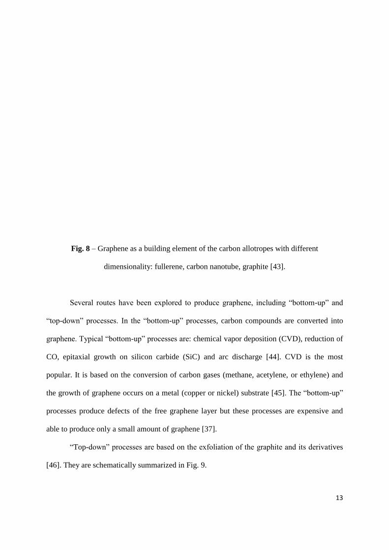
In addition to clays and CNTs, graphene and its derivatives have been widely analyzed
and studied as nanofiller of elastomer nanocomposites [35]. Graphene consists of sp2 carbon
atoms arranged in an atomically thick honeycomb structure [36]. Graphene is the two
dimensional allotrope of carbon and it is considered the building element of the carbon
allotropes with different dimensionality (Fig. 8). Graphite, the three dimensional allotrope,
consists of several graphene sheets stacked, bonded by π-π interactions and separate by 3.37
Å; CNTs (one dimensional) and fullerene (zero dimensional) are made by rolling and slicing
graphene sheets, respectively [37].
In 2004 graphene was isolated for the first time from graphite through a process called
micromechanical cleavage or scotch tape technique [38]. This nanoparticle presents
extraordinary mechanical properties, such as Young’s modulus of 1 TPa, tensile strength of
130 GPa [39], and has high thermal (5000 W/(m*K) [40] and electrical conductivities (6000
S/cm) [41]. Moreover, the surface area of graphene is about 2600 m2/g. These properties, its
gas impermeability [42] and the ability to be dispersed in polymeric matrices have created
potential nanofiller for nanocomposites.
13
Fig. 8 – Graphene as a building element of the carbon allotropes with different
dimensionality: fullerene, carbon nanotube, graphite [43].
Several routes have been explored to produce graphene, including “bottom-up” and
“top-down” processes. In the “bottom-up” processes, carbon compounds are converted into
graphene. Typical “bottom-up” processes are: chemical vapor deposition (CVD), reduction of
CO, epitaxial growth on silicon carbide (SiC) and arc discharge [44]. CVD is the most
popular. It is based on the conversion of carbon gases (methane, acetylene, or ethylene) and
the growth of graphene occurs on a metal (copper or nickel) substrate [45]. The “bottom-up”
processes produce defects of the free graphene layer but these processes are expensive and
able to produce only a small amount of graphene [37].
“Top-down” processes are based on the exfoliation of the graphite and its derivatives
[46]. They are schematically summarized in Fig. 9.
14
Fig. 9 – Top-down processes to produce graphene from graphite.
Mechanical exfoliation or cleavage is a relatively simple method to obtain graphene
from graphite, but in very limited quantity [38]. Graphite has been directly exfoliated via
sonication in the presence of polyvinylpyrrolidone [47] or N-methylpyrrolidone [48]. The
weak point of this method is the separation of graphene sheets from the bulk of graphite.
Nowadays, the most promising method to produce graphene in large scale consists of
two steps: in the first one, graphite is oxidized in in graphene oxide (GO) by strong oxidants
(H2O2, NaNO2, KMnO4, and KClO3) in presence of nitric and sulfuric acids. This phase lasts
10-12 hours and is supported by ultrasounds [44]. GO has a layered structure similar to that of
graphite but the interlayer space is between 6 and 10 Å. Moreover, the surface of the GO
sheets presents several functional groups: epoxide and hydroxyl on basal plane, and carbonyl
and carboxylic at the edge [37]. Subsequently, in the second step, GO is reduced and
exfoliated in graphene. GO can be reduced by chemical or thermal process. In the first route,
hydrazine or hydroquinone is used as a reductant and the ultrasounds induce the exfoliation in
graphene [13]. The cost and dangerous nature of the chemicals are the limit of this reduction
method. In the thermal route, GO is reduced and exfoliated by rapidly heating (>2000 °C/min)
in an inert atmosphere at high temperature (> 1000 °C). The absence of chemicals makes the
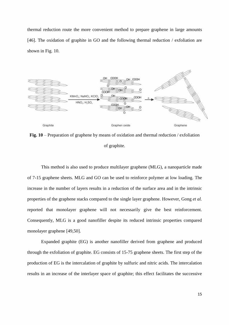
15
thermal reduction route the more convenient method to prepare graphene in large amounts
[46]. The oxidation of graphite in GO and the following thermal reduction / exfoliation are
shown in Fig. 10.
Fig. 10 – Preparation of graphene by means of oxidation and thermal reduction / exfoliation
of graphite.
This method is also used to produce multilayer graphene (MLG), a nanoparticle made
of 7-15 graphene sheets. MLG and GO can be used to reinforce polymer at low loading. The
increase in the number of layers results in a reduction of the surface area and in the intrinsic
properties of the graphene stacks compared to the single layer graphene. However, Gong et al.
reported that monolayer graphene will not necessarily give the best reinforcement.
Consequently, MLG is a good nanofiller despite its reduced intrinsic properties compared
monolayer graphene [49,50].
Expanded graphite (EG) is another nanofiller derived from graphene and produced
through the exfoliation of graphite. EG consists of 15-75 graphene sheets. The first step of the
production of EG is the intercalation of graphite by sulfuric and nitric acids. The intercalation
results in an increase of the interlayer space of graphite; this effect facilitates the successive
16
thermal exfoliation. The intercalated graphite is exfoliated into EG through a rapid heating at
high temperature [51].
Recently, bionanofillers, such as polysaccharides and wood fibers, have been proposed
as reinforcing nanomaterial for rubber nanocomposites because they are low cost
biodegradable materials [52,53].
1.3.1 Preparation of Rubber Nanocomposites
The properties of rubber nanocomposites depend strongly on how well the nanofillers
are dispersed in the elastomeric matrix. Nanoparticles tend to form aggregates; therefore their
dispersion is not easy. Obviously, the dispersion of the nanofiller strongly depends on the
preparation method of the nanocomposites. Thus, in the literature several preparation methods
have been discussed. The most popular are: melt compounding, solution mixing, latex
compounding, and in-situ polymerization [10,13].
The melt compounding is a direct way to mix elastomer, nanoparticles and the other
ingredients (curatives, etc.) using mainly two machines (described in the previous sections):
the internal mixer and the two-roll mill (Fig. 4). This method is the most cost effective and
environmental friendly because solvents are not needed [54,55]; it is also completely
compatible with rubber industry, where the two machines are usually employed. Nevertheless,
the melt compounding procedure often doesn’t guarantee a good dispersion of nanofillers [56-
58]. Moreover, the handling and the milling of the nanoparticles with traditional machines are
not easy. For example, an inappropriate handling of nanofillers on the two-roll mills will
result in a small cloud of nanoparticles dispersed in the air.
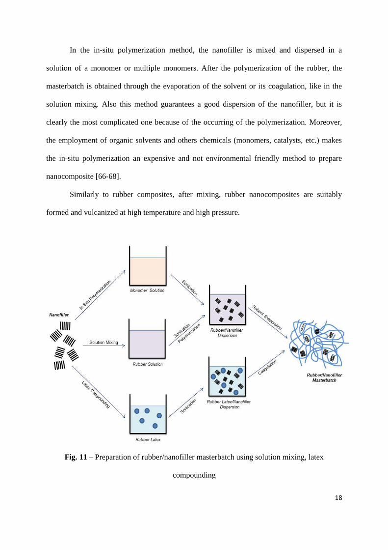
In contrast, the other three methods are not direct because they include the preparation
of a masterbatch (Fig. 11), which consists of only rubber and nanofiller. Successively, the
17
masterbatch is mixed together with the other ingredients of the rubber nanocomposites in the
typical machines of the rubber manufacturing (internal mixer or in the two roll mill). The
masterbatch simplifies tremendously the handling of the nanoparticles because it is a solid
ingredient that can be easily added in the two-roll mill or the internal mixer. Unfortunately, a
suitable solvent is necessary in the solution mixing, the latex compounding, and the in-situ
polymerization.
and in situ polymerization, in the case of layered nanofiller.
In the solution mixing the solvent should be able to dissolve the rubber and suspend
the nanofiller. The most common solvents are toluene, tetrahydrofuran and
dimethylformammide. The rubber solution and the suspension of the nanofiller are mixed
together using mechanical stirring and ultrasounds. Usually, the sonication improves the
dispersion of the nanoparticles because the ultrasound waves break the aggregates of the
nanofiller. The masterbatch is obtained after the evaporation of the solvent. Alternatively, the
masterbatch is coagulated by adding another solvent. Although the solution mixing is not an
environmental friendly method to prepare rubber nanocomposites because organic solvents
are necessary, it is very popular because it provides a good dispersion of the nanofiller [59-
63].
In the latex compounding the solvent is water. Some common rubbers are
commercially available in the latex form: this consists of fine elastomers particles dispersed in
water. Hence, in this method nanofillers are mixed with rubbers in latex form by means of
mechanical stirring and sonication. The mixture is then coagulated and the masterbatch is
dried. Latex compounding yields to good dispersion of the nanofiller in an environmental
friendly way because of the use of water; this is biggest advantage of this method [64,65].
Unfortunately, not all rubbers are available in the latex form.
18
In the in-situ polymerization method, the nanofiller is mixed and dispersed in a
solution of a monomer or multiple monomers. After the polymerization of the rubber, the
masterbatch is obtained through the evaporation of the solvent or its coagulation, like in the
solution mixing. Also this method guarantees a good dispersion of the nanofiller, but it is
clearly the most complicated one because of the occurring of the polymerization. Moreover,
the employment of organic solvents and others chemicals (monomers, catalysts, etc.) makes
the in-situ polymerization an expensive and not environmental friendly method to prepare
nanocomposite [66-68].
Similarly to rubber composites, after mixing, rubber nanocomposites are suitably
formed and vulcanized at high temperature and high pressure.
Fig. 11 – Preparation of rubber/nanofiller masterbatch using solution mixing, latex
compounding
19
2. Scientific Goal
High loading (>40 phr) of CB or silica are usually used to achieve the requested
mechanical and functional properties of rubber composites. In recent years several
nanoparticles (such as LSs, CNTs, EG and graphene) have been proposed as nanofiller for
elastomer nanocomposites. When incorporated appropriately, these nanoparticles can
significantly improve the mechanical and functional properties (hardness, modulus, gas
barrier properties) of the rubbers at extremely small loading.
In this study the multifunctional impact of the MLG on the different properties
(curing, rheological, mechanical and functional) of the unvulcanized and vulcanized rubbers
nanocomposites is largely investigated. Thus MLG is proposed as an efficient nanofiller for
rubbers, in order to improve the overall performances of unfilled rubbers and rubber/CB
composites, and also to reduce the filler content. MLG is a nanoparticle made of just
approximately 10 graphene sheets and has recently become commercially available for mass-
product nanocomposites.
The reinforcement effect of the nanofiller depends on several factors: intrinsic
properties, geometric parameters of the nanofiller, the dispersion and the concentrations of the
nanofiller in the elastomeric matrix and the interactions between polymeric chains and the
nanofiller. In order to investigate the reinforcing effect of the tested nanoparticles, systematic
comparisons between unfilled rubbers and nanocomposites prepared through different
methods, nanocomposites with different MLG content, nanocomposites based on different
rubbers, respectively, are studied.
The efficiency of MLG is determined by means of a multi-methodic comprehensive
characterization: curing and rheological properties of the uncured rubber nanocomposites; a
large variety of mechanical properties and different functional properties (gas barrier and
flame retardant properties, electrical and thermal conductivities) of the cured nanocomposites.
20
The characterization includes also the morphological analysis of the surface of the
nanocomposites. Moreover the protective effect, against the weathering aging, of MLG is
studied and illustrated.
In the first paper the effect of the preparation method and hence of the nanofiller
dispersion on the properties of the rubber nanocomposites is investigated. CIIR/MLG
nanocomposites with the same MLG content (3 phr) were prepared directly on a two-roll mill
(melt compounding) and by pre-mixing MLG with CIIR using an ultrasonically-assisted
solution mixing procedure followed by two-roll milling, in order to evaluate the effectiveness
of these different preparation methods.
Since the solution mixing provided a homogeneous dispersion of the MLG and hence
nanocomposite with the better properties, this method was used for the following
investigations. The concentration of the nanofiller is another crucial parameter in the
reinforcement of rubber nanocomposites. Therefore, in the second paper, CIIR/MLG
nanocomposites with different MLG loadings are characterized in order to determine the
effect of the nanofiller concentration on the properties of the nanocomposites.
The chemical structure of the rubber and hence the interactions between elastomeric
chains and nanofiller play an important role in the reinforcement of rubber nanocomposites.
Thus nanocomposites with different rubbers and the same loading of MLG (3 phr) are
characterized in the third paper in order to understand the effect of the rubber/nanofiller
interactions on the properties of nanocomposites. The investigated rubbers are: CIIR, NBR,
NR and SBR. These elastomers are usually employees in multi sector applications, such us
tires, gloves, shoes and seals.
In the last paper of this study, 3 phr of MLG were added to CIIR/CB composites in
order to partly replace CB or to improve performance, respectively. The combination of
21
nanoparticles and traditional fillers is a reasonable approach to exploit nanocomposites in the
usual industrial applications.
22
3. Publications and Manuscripts
3.1 Multilayer Graphene / Chlorine – Isobutene – Isoprene Rubber
Nanocomposites: The Effect of Dispersion
Daniele Frasca, Dietmar Schulze, Volker Wachtendorf, Michael Morys and Bernhard
Schartel, Polym. Adv. Technol. 2016, 27 (7), 872-881.
This article was published.
http://dx.doi.org/10.1002/pat.3740
Author Contribution:
Designing the working packages and the approach to this study;
Masterbatches, rubber compounds and samples preparation;
Experiments for rheological, curing and mechanical properties;
Experiments for electrical conductivities;
Data evaluation;
Manuscript Preparation;
33
3.2 Multilayer Graphene (MLG) Chlorine Isobutyl Isoprene Rubber
Nanocomposites: Influence of the MLG-Concentration on Physical
and Flame Retardant Properties
Daniele Frasca, Dietmar Schulze, Martin Böhning, Bernd Krafft and Bernhard Schartel,
Rubber Chem. Technol. 2016, 89 (2), 316-344.
This article was published.
http://dx.doi.org/10.5254/rct.15.84838
Author Contribution:
Designing the working packages and the approach to this study;
Masterbatches, rubber compounds and samples preparation;
Experiments for rheological, curing and mechanical properties;
Experiments for electrical conductivities;
Data evaluation;
Manuscript Preparation;
53
3.3 Multifunctional multilayer graphene / elastomer nanocomposites
Daniele Frasca, Dietmar Schulze, Volker Wachtendorf, Christian Huth and Bernhard
Schartel, Eur. Polym. J. 2015, 71, 99-113.
This article was published.
http://dx.doi.org/10.1016/j.eurpolymj.2015.07.050

54
Author Contribution:
Designing the working packages and the approach to this study;
Masterbatches, rubber compounds and samples preparation;
Experiments for rheological, curing and mechanical properties;
Experiments for UV-Vis Absorbtions;
Data evaluation;
Manuscript Preparation;
70
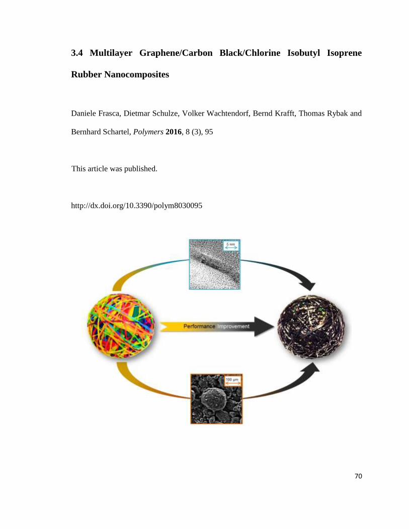
3.4 Multilayer Graphene/Carbon Black/Chlorine Isobutyl Isoprene
Rubber Nanocomposites
Daniele Frasca, Dietmar Schulze, Volker Wachtendorf, Bernd Krafft, Thomas Rybak and
Bernhard Schartel, Polymers 2016, 8 (3), 95
This article was published.
http://dx.doi.org/10.3390/polym8030095
71
Author Contribution:
Designing the working packages and the approach to this study;
Masterbatches, rubber compounds and samples preparation;
Experiments for rheological, curing and mechanical properties;
Experiments for UV-Vis Absorptions;
Data evaluation;
Manuscript Preparation;
polymers
Article
Multilayer Graphene/Carbon Black/Chlorine IsobutylIsoprene Rubber Nanocomposites
Daniele Frasca, Dietmar Schulze, Volker Wachtendorf, Bernd Krafft, Thomas Rybak andBernhard Schartel *
Bundesanstalt für Materialforschung und–prüfung (BAM), Unter den Eichen 87, 12205 Berlin, Germany;[email protected] (D.F.); [email protected] (D.S.); [email protected] (V.W.);[email protected] (B.K.); [email protected] (T.R.)* Correspondence: [email protected]; Tel.: +49-30-8104-1021
Academic Editor: Walter Remo CaseriReceived: 10 February 2016; Accepted: 14 March 2016; Published: 22 March 2016
Abstract: High loadings of carbon black (CB) are usually used to achieve the properties demandedof rubber compounds. In recent years, distinct nanoparticles have been investigated to replaceCB in whole or in part, in order to reduce the necessary filler content or to improve performance.Multilayer graphene (MLG) is a nanoparticle made of just 10 graphene sheets and has recentlybecome commercially available for mass-product nanocomposites. Three phr (part for hundredrubbers) of MLG are added to chlorine isobutyl isoprene rubber (CIIR)/CB composites in order toreplace part of the CB. The incorporation of just 3 phr MLG triples the Young’s modulus of CIIR;the same effect is obtained with 20 phr CB. The simultaneous presence of three MLG and CB alsodelivers remarkable properties, e.g. adding three MLG and 20 phr CB increased the hardness asmuch as adding 40 phr CB. A comprehensive study is presented, showing the influence on a varietyof mechanical properties. The potential of the MLG/CB combination is illustrated to reduce the fillercontent or to boost performance, respectively. Apart from the remarkable mechanical properties,the CIIR/CB/MLG nanocomposites showed an increase in weathering resistance.
Keywords: nanocomposites; rubber; multilayer graphene; carbon black
1. Introduction
Carbon black (CB) is largely used as filler to improve the performance of rubber composites. CB isproduced by the partial combustion or thermal cracking of heavy petroleum products or natural gas.The fine particles of CB always form aggregates and agglomerates [1] and high filler loadings (>30 phr)are usually needed to obtain the mechanical performance desired for elastomer composites [2,3].
Ever since Toyota presented layered silicate/polyamide nanocomposites in the early 1990s [4],polymer research has been concentrating on nanocomposites, and several nanoparticles havebeen used to reinforce rubbers at even low concentrations. Typical nanofillers include: layeredsilicates [5,6], spherical nanosilica [7,8], carbon nanotubes [9,10], organically modified clay [11–13]and bionanofillers [14,15]. The discovery of graphene [16] has created a new potential nanofiller forpolymer nanocomposites [17,18]. Graphene is the 2-D carbon allotrope consisting of a sheet of sp2carbon atoms arranged in a honeycomb structure [19].
In this study, multilayer graphene (MLG) was used as a nanofiller. It presents a large specificsurface area BET (Brunauer Emmett Teller): 250 m2/g. This parameter describes quite well the degreeof exfoliation and thus the number of layers in graphene stacks [20,21]. A single graphene sheethas a BET of about 2600 m2/g. Therefore the MLG used is composed of approximately 10 graphenesheets. Recently, MLG has become commercially available at a reasonable price by applying a modifiedHummer method. Materials with a specific surface area BET between 80 and 200 m2/g and then stacks
Polymers 2016, 8, 95; doi:10.3390/polym8030095 www.mdpi.com/journal/polymers
Polymers 2016, 8, 95 2 of 17
consisting of more than 15 sheets are frequently referred to as graphene in the literature. However,we would like to use the following denotation: graphene (less than 7 layers), MLG (7–15 layers)and expanded graphite (15–75 layers) [22–25]. Even low loadings of MLG already reinforce the finalproperties of rubber nanocomposites [26,27].
The rubber tested was chlorine isobutyl isoprene rubber (CIIR), the chlorinated form of isobutyleneisoprene rubber (IIR), or butyl rubber for short. It is a copolymer of isobutylene (97%–98%) and asmall amount of isoprene (2%–3%). CIIR was developed to increase the curing rate of IIR, allowingcontemporary vulcanization with natural rubber and styrene-butadiene rubber. Because CIIR presentsa very airtight structure, it is the most important rubber for the inner linings of tubeless tires today [28].
The combination of nanoparticles and traditional fillers is a reasonable approach to exploitnanocomposites in usual industrial applications. Thus, in this study, 3 phr of MLG were added toCIIR/CB composites in order to replace CB in part or to boost performance, respectively. The CBused has a specific surface area BET between 70 and 100 m2/g. The CIIR/CB compounds wereprepared by melt-compounding using a two-roll mill. The compounds with MLG were preparedby pre-mixing MLG with CIIR by an ultrasonically-assisted solution mixing procedure followed bytwo-roll milling [29].
A low loading of 3 phr MLG was used and its significant influence on the rheological, curingand mechanical properties of CIIR and CIIR/CB composites investigated. Improvements were found,such as the increase in Young’s modulus by a factor of 3 and the replacement of 20 phr CB.
Rubbers are very sensitive to weathering exposure: the combination of oxidative gases and UVdegrades the elastomer matrix through multi-step photo-oxidation [30]. The UV absorption andradical scavenging of both CB and MLG was addressed and the improved weathering resistance of theCIIR/CB/MLG nanocomposites discussed.
2. Materials and Methods
2.1. Materials
CIIR (Chlorobutyl 1240), zinc oxide (Zincoxyd Activ), and mercaptobenzthiazole disulfide(MBTS, Vulcacit DM/C-MG) were obtained from LANXESS Deutschland GmbH, Leverkusen,Germany. Commercially available MLG (EXG R98 250) was produced by Graphit Kropfmühl AG,Hauzenberg, Germany. CB660 (CXN660) and CB (CXN330) were supplied by Orion EngineeredCarbons GmbH, Frankfurt, Germany. Stearic acid (stearic acid pure) was produced by Applichem,Darmstadt, Germany. Sulfur was obtained from Merck, Germany. Struktol (Struktol 40 MS Flakes)was supplied by Schill + Seilacher, Böbligen, Germany. Analytical-degree toluene was obtained fromFisher Chemical, Schwerte, Germany.
2.2. Preparation of the CIIR Compounds
MLG was dispersed in a toluene/CIIR solution using a sonicator (UPS 400S, Hielscher, Teltow,Germany) for 3 h. Then the mixture was stirred for 2 h. The ratio of elastomer to MLG was 7:1and the concentration of MLG in the solution was 1 mg/mL. The master batch was obtained afterevaporation of the solvent (60 ˝C, 150 mbar) using a rotary evaporator (Hei Vap Value, Hiedolph,Schwabach, Germany).
CIIR and the other ingredients, as listed in Table 1, were mixed directly in a two-roll mill(Lab Walzwerk MT 611 ˆ 1311, Rubicon, Halle, Germany). The compounds were prepared in threestages. In the first stage, CIIR was mixed with zinc oxide, stearic acid, CB660 and Struktol. In thesecond stage, the CIIR/MLG master batch or CB was added to the rubber compound. In the third stage,the curatives (sulfur and MBTS) were added. For the compounds without MLG and CB, the secondstage was not performed. For all compounds, the rolls were set to a temperature of 50 ˝C, a speed of19 RPM a friction ratio of 1.1:1 and a mixing time of 20 min.
Polymers 2016, 8, 95 3 of 17
Table 1. Formulation of the CIIR (chlorine isobutyl isoprene rubber) compounds in parts per hundredof rubber (phr).
Ingredients CIIR CIIR/MLG3 CIIR/CB20 CIIR/CB20/MLG3 CIIR/CB30 CIIR/CB30/MLG3 CIIR/CB40
CIIR 100 100 100 100 100 100 100Zinc oxide 3.0 3.0 3.0 3.0 3.0 3.0 3.0Stearic acid 2.0 2.0 2.0 2.0 2.0 2.0 2.0
CB660 0.5 0.5 0.5 0.5 0.5 0.5 0.5Struktol 7.0 7.0 7.0 7.0 7.0 7.0 7.0Sulfur 0.5 0.5 0.5 0.5 0.5 0.5 0.5MBTS 1.5 1.5 1.5 1.5 1.5 1.5 1.5
CB - - 20 20 30 30 40MLG - 3 - 3 - 3 -
The curing time (t100) was obtained by Dynamic Moving Die Rheometer (D-MDR 300, MontechWerkstoffprüfmaschinen, Buchen, Germany). It was 20 min for samples of 2-mm thickness and 25 for6-mm thickness; the samples were vulcanized at a pressure of 300 bar and a temperature of 180 ˝C.
2.3. Characterization
UV-Vis absorption of freshly produced aqueous dispersions of CB (0.010 and 0.015 mg/mL), MLG(0.005 mg/mL) and their mixture (CB = 0.010 mg/mL plus MLG = 0.005 mg/mL) were measuredwith a Cary 300 Scan (Varian, Sidney (New South Wales), Australia) double monochromator doublechannel spectrometer in quartz cuvettes. For the measurement, the cuvettes were placed in front ofa LabSphere® DRA-30I integrating sphere, which was used as samples producing stray light wereinvestigated. The wavelength range was 800 to 220 nm with a step width 1 nm. MLG and CB weresonicated in water for 2 h. A baseline correction was carried out using a cuvette filled with pure water.
The radical oxidation of cumene (10 mL) was performed to determine the radical scavengingbehavior of the tested carbon particles; AIBN (10 mg) was the initiator [31]. The studied reactionconsists of 3 phases:
Initiation: AIBNÑ r‚ + RHÑ R‚
Propagation: R‚ + O2 Ñ RO2‚ + RHÑ ROOH + R‚
Termination: 2 RO2‚Ñ inactive products
(RH = cumene, R‚ = cumylalkyl radical, RO2‚ = cumylperxoy radical, ROOH = cumylhydroperoxide).
At 60 ˝C, the initiator (AIBN) decomposed into radicals (initiation). Then, the radicals reactedwith cumene. This reaction resulted in cumene alkyl radicals, which were oxidized by oxygen intocumylperxoy radicals in the propagation stage. Furthermore, cumylperxoy radicals reacted withcumene, forming other cumene alkyl radicals. When cumylperoxy radicals reacted with each other,the reaction ended (termination).
MLG (5 mg, 30 mg) and CB (30 mg) were sonicated 10 minutes in the cumene. Than AIBN wasadded to the MLG/cumene dispersion and the oxygen consumption was controlled by measuring thepressure decrease in the closed air volume above the reaction mixture.
Using a Dynamic Moving Die Rheometer (D-MDR 3000, Montech Werkstoffprüfmaschinen),the dynamic viscosity (η’) of the uncured samples (5 g) was measured as a function of frequency.The temperature was 100 ˝C and the strain amplitude was 1%. The storage modulus (G’) as afunction of the amplitude was also measured with a Dynamic Moving Die Rheometer (D-MDR 3000,Montech Werkstoffprüfmaschinen) on the uncured samples (5 g). The temperature was 60 ˝C and thefrequency 1 Hz.
Scanning electron microscopy (SEM) micrographs of the freeze-fractured gold-coated surfacesof vulcanized samples were taken with a scanning electron microscope (Zeiss EVO MA 10) using anacceleration voltage of 10 kV. The micrographs of CB and MLG were taken without gold sputtering.
Polymers 2016, 8, 95 4 of 17
The samples (80 nm thick), for the TEM micrographs were prepared using a cryo microtome(Ultracut UCT, Leica, Wetzlar, Germany) at ´100 ˝C. The TEM micrographs of CIIR-MLG-3 were takenwith JEM-2200 FS (Jeol, Peabody, MA, USA); the acceleration voltage was 200 kV.
Tensile tests were performed on 5 dumbbell specimens (2-mm thickness) according to DIN 53504;Young’s modulus tests were performed on 3 dumbbell specimens (2-mm thickness) according to ISO527; and shore A hardness measurements were performed according to ISO 7619-1 on 3 samples of6-mm thickness.
The storage modulus (G1) and dynamic loss factor (tan δ) were measured on 2 samples of 2-mmthickness as a function of temperature using an MCR 501 Rheometer (Anton Paar, Ostfildern, Germany).The frequency was 1 Hz, the strain amplitude was 0.1%, the temperature range of ´80 to 70 ˝C andthe heating rate was 1 ˝C/min.
The weathering/ageing process of dumbbell 10 test specimens (2 mm thickness) was conductedusing the 24 h weathering cycle in Table 2 repeatedly conducted over 1000 h (for one half of thesamples) and 1500 h (for the other half), respectively. The conditions of the cycle contain a step at´10 ˝C, which could bring mechanical tension into the sample, as well as rain phases, which cancause extraction of soluble or dispersible components off the system. Weathering was carried outusing a fluorescent UV lamp device of the type Global UV Test 200 (Weiss Umwelttechnik GmbH,Reiskirchen, Germany), according to ISO 4892-3. The spectral distribution—characterized by UVA-340nm fluorescent lamps (ISO 4892-3, type 1A) and spectrally neutral filtering using a PVDF-membranein the device’s door—was measured in the sample plane by means of a MSS 2040 spectro-radiometer.As the spectral distribution from the fluorescent lamps is limited to UV and near VIS, radiation heatingcan be neglected (TSurface ´ TChamber < 2 K). Thus, the degradation-relevant temperature can becontrolled very closely over a wide range. The device allows full humidity control and uses waterspraying for the wetting phases. UV-irradiance was 40 W/m2.
Table 2. Weathering exposure cycle. Continuous UV irradiation at 40 W/m2.
Time/h Temperature/˝C Humidity
4 25 Rain4 80 <10%4 25 Rain4 80 <10%4 25 Rain4 ´10 <10%
3. Results
3.1. Characterization of MLG and CB
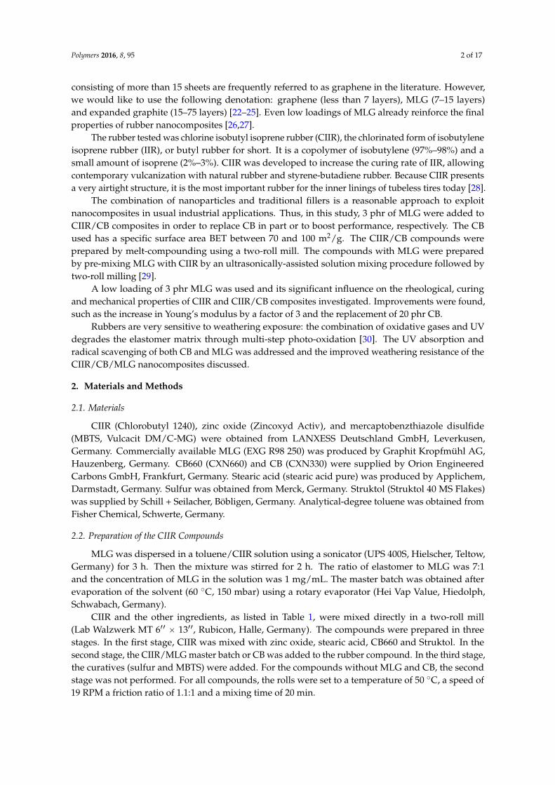
The left side of Figure 1 shows the SEM micrographs of the MLG used. The MLG particles haddifferent shapes, but most of them present a worm-like shape (Figure 1a). Some particles are small witha diameter about 50 µm and others very big with a length of about 1 mm. Nevertheless, each particleconsists of several MLG stacks (Figure 1b). Figure 1c shows the highly delaminated structure of MLG,in good correspondence to the high BET.
The SEM micrographs of CB are shown in the right side of Figure 1. The CB particles presented aspherical shape with diameters between 20 and 100 µm. Furthermore, the surface of the particles turnsout to be completely smooth. At this magnification, no aggregates of CB particles were observed.
Polymers 2016, 8, 95 5 of 17
Polymers 2016, 8, 95 5 of 16
Figure 1. SEM micrographs of (a–c) MLG and (d–f) CB.
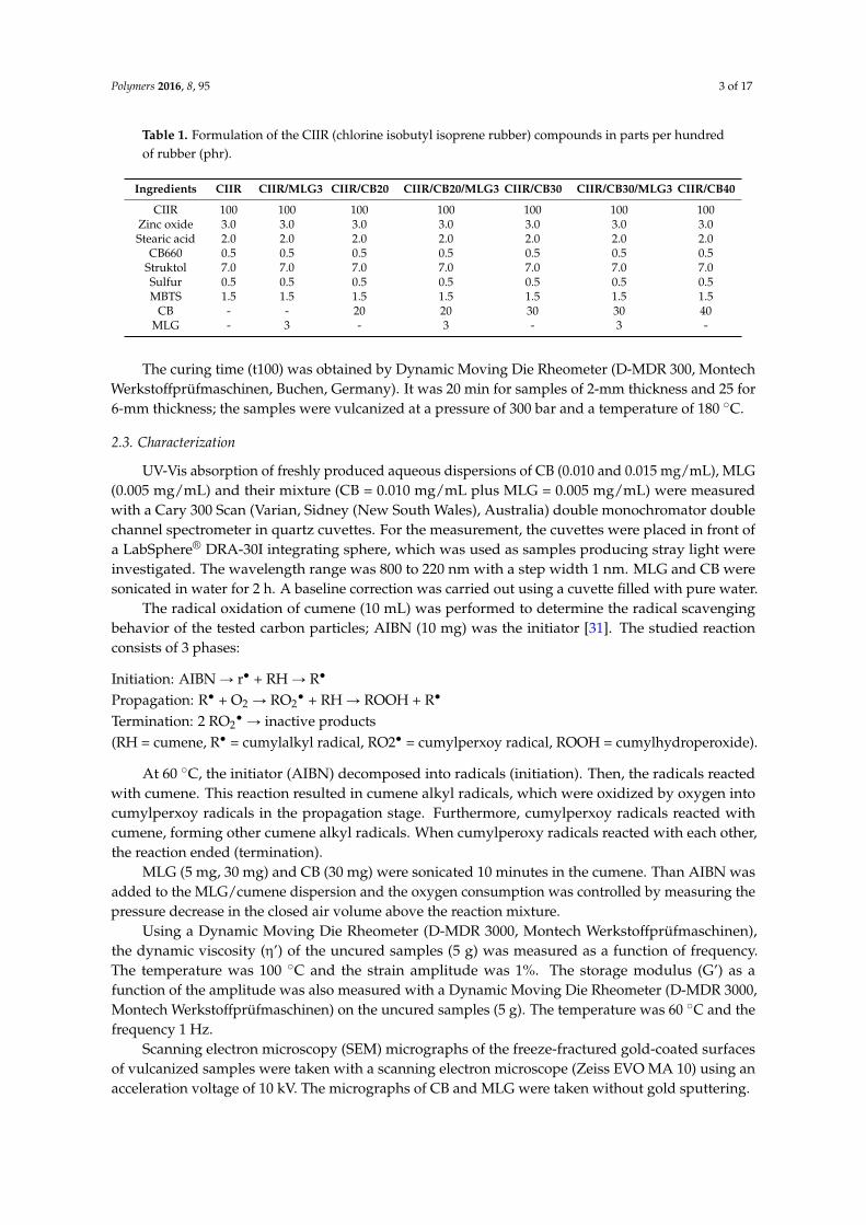
Figure 2. UV-Vis absorption of water dispersions of CB, MLG and their mixture.
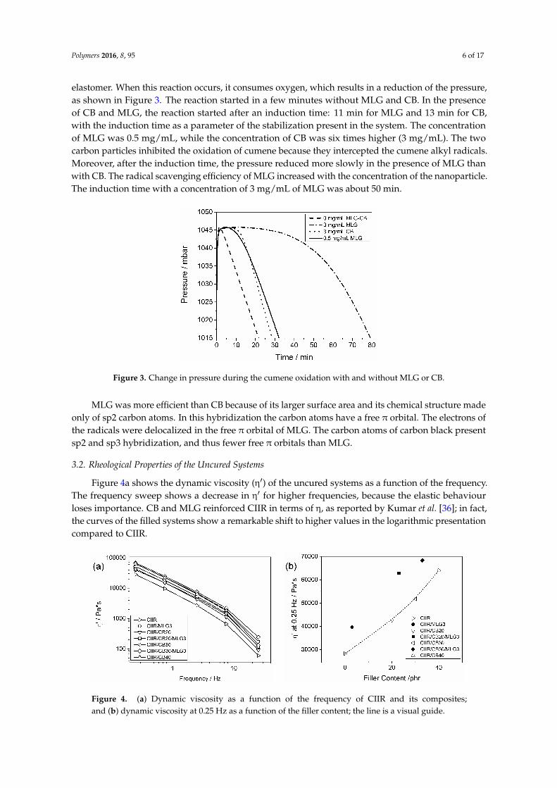
The radical scavenging efficiency of the CB and MLG was determined by studying the radical oxidation of cumene [35], which is thought to be a model for autoxidative radical oxidation of the elastomer. When this reaction occurs, it consumes oxygen, which results in a reduction of the pressure, as shown in Figure 3. The reaction started in a few minutes without MLG and CB. In the presence of CB and MLG, the reaction started after an induction time: 11 min for MLG and 13 min for CB, with the induction time as a parameter of the stabilization present in the system. The concentration of MLG was 0.5 mg/mL, while the concentration of CB was six times higher (3 mg/mL). The two carbon particles inhibited the oxidation of cumene because they intercepted the cumene alkyl radicals. Moreover, after the induction time, the pressure reduced more slowly in the presence of MLG than with CB. The radical scavenging efficiency of MLG increased with the concentration of the nanoparticle. The induction time with a concentration of 3 mg/mL of MLG was about 50 min.
Figure 1. SEM micrographs of (a–c) MLG and (d–f) CB.
Figure 2 reports the UV-Vis absorption of aqueous dispersions of CB, MLG and a mixture of thetwo carbon particles. All of the spectra presented a maximum of absorption of about 270 nm, whichcorresponds to the electronic transition from the bonding orbital π to the anti-bonding orbital π* [32].This transition is typical for carbon particles like MLG and CB [33]. The UV band of the π-π* transitionis more defined in the spectrum of MLG (0.005 mg/mL), where it is almost a peak, than in the spectraof CB (0.010 and 0.015 mg/mL), where it is large and rough . MLG consists of only sp2 carbon atoms,whereas CB is made of sp2 and sp3 carbon atoms; in the presence of sp3 carbon atoms the UV bandcaused by π-π* transition is reduced [34]. The spectra of the CB/MLG mixture presented an evidentpeak at about 270 nm because of the presence of the tested nanoparticle. Moreover, the absorption ofthe mixture, with a final concentration of 0.015 mg/mL, was higher than for the same concentration ofCB. Hence, MLG presented a higher UV-Vis. absorption than CB.
Polymers 2016, 8, 95 5 of 16
Figure 1. SEM micrographs of (a–c) MLG and (d–f) CB.
Figure 2. UV-Vis absorption of water dispersions of CB, MLG and their mixture.
The radical scavenging efficiency of the CB and MLG was determined by studying the radical oxidation of cumene [35], which is thought to be a model for autoxidative radical oxidation of the elastomer. When this reaction occurs, it consumes oxygen, which results in a reduction of the pressure, as shown in Figure 3. The reaction started in a few minutes without MLG and CB. In the presence of CB and MLG, the reaction started after an induction time: 11 min for MLG and 13 min for CB, with the induction time as a parameter of the stabilization present in the system. The concentration of MLG was 0.5 mg/mL, while the concentration of CB was six times higher (3 mg/mL). The two carbon particles inhibited the oxidation of cumene because they intercepted the cumene alkyl radicals. Moreover, after the induction time, the pressure reduced more slowly in the presence of MLG than with CB. The radical scavenging efficiency of MLG increased with the concentration of the nanoparticle. The induction time with a concentration of 3 mg/mL of MLG was about 50 min.
Figure 2. UV-Vis absorption of water dispersions of CB, MLG and their mixture.
The radical scavenging efficiency of the CB and MLG was determined by studying the radicaloxidation of cumene [35], which is thought to be a model for autoxidative radical oxidation of the
Polymers 2016, 8, 95 6 of 17
elastomer. When this reaction occurs, it consumes oxygen, which results in a reduction of the pressure,as shown in Figure 3. The reaction started in a few minutes without MLG and CB. In the presenceof CB and MLG, the reaction started after an induction time: 11 min for MLG and 13 min for CB,with the induction time as a parameter of the stabilization present in the system. The concentrationof MLG was 0.5 mg/mL, while the concentration of CB was six times higher (3 mg/mL). The twocarbon particles inhibited the oxidation of cumene because they intercepted the cumene alkyl radicals.Moreover, after the induction time, the pressure reduced more slowly in the presence of MLG thanwith CB. The radical scavenging efficiency of MLG increased with the concentration of the nanoparticle.The induction time with a concentration of 3 mg/mL of MLG was about 50 min.Polymers 2016, 8, 95 6 of 16
Figure 3. Change in pressure during the cumene oxidation with and without MLG or CB.
MLG was more efficient than CB because of its larger surface area and its chemical structure made only of sp2 carbon atoms. In this hybridization the carbon atoms have a free π orbital. The electrons of the radicals were delocalized in the free π orbital of MLG. The carbon atoms of carbon black present sp2 and sp3 hybridization, and thus fewer free π orbitals than MLG.
3.2. Rheological Properties of the Uncured Systems
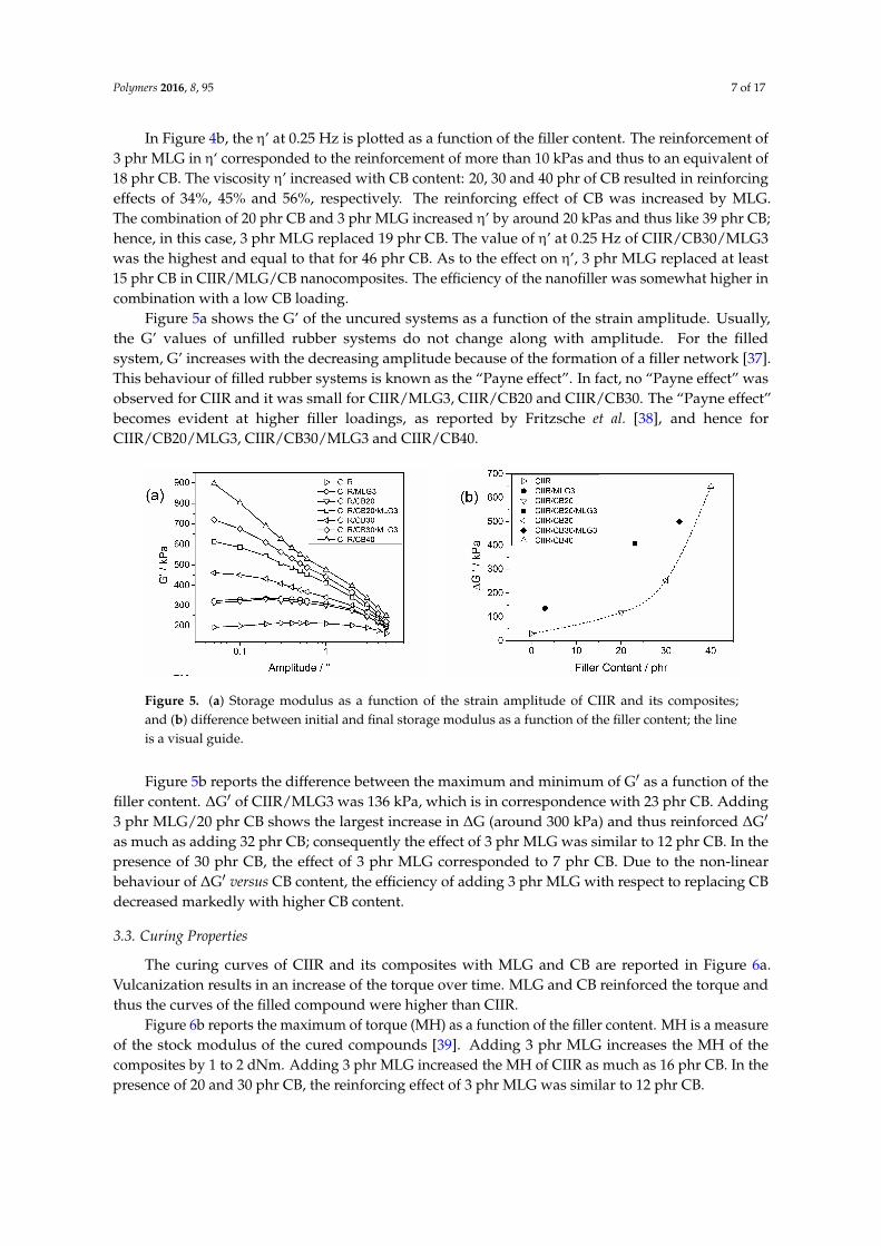
Figure 4a shows the dynamic viscosity (η′) of the uncured systems as a function of the frequency. The frequency sweep shows a decrease in η′ for higher frequencies, because the elastic behaviour loses importance. CB and MLG reinforced CIIR in terms of η, as reported by Kumar et al. [36]; in fact, the curves of the filled systems show a remarkable shift to higher values in the logarithmic presentation compared to CIIR.
Figure 4. (a) Dynamic viscosity as a function of the frequency of CIIR and its composites; and (b) dynamic viscosity at 0.25 Hz as a function of the filler content; the line is a visual guide.
In Figure 4b, the η’ at 0.25 Hz is plotted as a function of the filler content. The reinforcement of 3 phr MLG in η‘ corresponded to the reinforcement of more than 10 kPas and thus to an equivalent of 18 phr CB. The viscosity η’ increased with CB content: 20, 30 and 40 phr of CB resulted in reinforcing effects of 34%, 45% and 56%, respectively. The reinforcing effect of CB was increased by MLG. The combination of 20 phr CB and 3 phr MLG increased η’ by around 20 kPas and thus like 39 phr CB; hence, in this case, 3 phr MLG replaced 19 phr CB. The value of η’ at 0.25 Hz of CIIR/CB30/MLG3 was the highest and equal to that for 46 phr CB. As to the effect on η’, 3 phr MLG replaced at least 15 phr CB in CIIR/MLG/CB nanocomposites. The efficiency of the nanofiller was somewhat higher in combination with a low CB loading.
Figure 3. Change in pressure during the cumene oxidation with and without MLG or CB.
MLG was more efficient than CB because of its larger surface area and its chemical structure madeonly of sp2 carbon atoms. In this hybridization the carbon atoms have a free π orbital. The electrons ofthe radicals were delocalized in the free π orbital of MLG. The carbon atoms of carbon black presentsp2 and sp3 hybridization, and thus fewer free π orbitals than MLG.
3.2. Rheological Properties of the Uncured Systems
Figure 4a shows the dynamic viscosity (η1) of the uncured systems as a function of the frequency.The frequency sweep shows a decrease in η1 for higher frequencies, because the elastic behaviourloses importance. CB and MLG reinforced CIIR in terms of η, as reported by Kumar et al. [36]; in fact,the curves of the filled systems show a remarkable shift to higher values in the logarithmic presentationcompared to CIIR.
Polymers 2016, 8, 95 6 of 16
Figure 3. Change in pressure during the cumene oxidation with and without MLG or CB.
MLG was more efficient than CB because of its larger surface area and its chemical structure made only of sp2 carbon atoms. In this hybridization the carbon atoms have a free π orbital. The electrons of the radicals were delocalized in the free π orbital of MLG. The carbon atoms of carbon black present sp2 and sp3 hybridization, and thus fewer free π orbitals than MLG.
3.2. Rheological Properties of the Uncured Systems
Figure 4a shows the dynamic viscosity (η′) of the uncured systems as a function of the frequency. The frequency sweep shows a decrease in η′ for higher frequencies, because the elastic behaviour loses importance. CB and MLG reinforced CIIR in terms of η, as reported by Kumar et al. [36]; in fact, the curves of the filled systems show a remarkable shift to higher values in the logarithmic presentation compared to CIIR.
Figure 4. (a) Dynamic viscosity as a function of the frequency of CIIR and its composites; and (b) dynamic viscosity at 0.25 Hz as a function of the filler content; the line is a visual guide.
In Figure 4b, the η’ at 0.25 Hz is plotted as a function of the filler content. The reinforcement of 3 phr MLG in η‘ corresponded to the reinforcement of more than 10 kPas and thus to an equivalent of 18 phr CB. The viscosity η’ increased with CB content: 20, 30 and 40 phr of CB resulted in reinforcing effects of 34%, 45% and 56%, respectively. The reinforcing effect of CB was increased by MLG. The combination of 20 phr CB and 3 phr MLG increased η’ by around 20 kPas and thus like 39 phr CB; hence, in this case, 3 phr MLG replaced 19 phr CB. The value of η’ at 0.25 Hz of CIIR/CB30/MLG3 was the highest and equal to that for 46 phr CB. As to the effect on η’, 3 phr MLG replaced at least 15 phr CB in CIIR/MLG/CB nanocomposites. The efficiency of the nanofiller was somewhat higher in combination with a low CB loading.
Figure 4. (a) Dynamic viscosity as a function of the frequency of CIIR and its composites;and (b) dynamic viscosity at 0.25 Hz as a function of the filler content; the line is a visual guide.
Polymers 2016, 8, 95 7 of 17
In Figure 4b, the η’ at 0.25 Hz is plotted as a function of the filler content. The reinforcement of3 phr MLG in η‘ corresponded to the reinforcement of more than 10 kPas and thus to an equivalent of18 phr CB. The viscosity η’ increased with CB content: 20, 30 and 40 phr of CB resulted in reinforcingeffects of 34%, 45% and 56%, respectively. The reinforcing effect of CB was increased by MLG.The combination of 20 phr CB and 3 phr MLG increased η’ by around 20 kPas and thus like 39 phr CB;hence, in this case, 3 phr MLG replaced 19 phr CB. The value of η’ at 0.25 Hz of CIIR/CB30/MLG3was the highest and equal to that for 46 phr CB. As to the effect on η’, 3 phr MLG replaced at least15 phr CB in CIIR/MLG/CB nanocomposites. The efficiency of the nanofiller was somewhat higher incombination with a low CB loading.
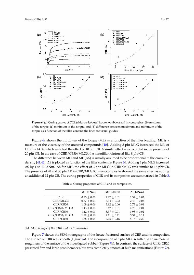
Figure 5a shows the G’ of the uncured systems as a function of the strain amplitude. Usually,the G’ values of unfilled rubber systems do not change along with amplitude. For the filledsystem, G’ increases with the decreasing amplitude because of the formation of a filler network [37].This behaviour of filled rubber systems is known as the “Payne effect”. In fact, no “Payne effect” wasobserved for CIIR and it was small for CIIR/MLG3, CIIR/CB20 and CIIR/CB30. The “Payne effect”becomes evident at higher filler loadings, as reported by Fritzsche et al. [38], and hence forCIIR/CB20/MLG3, CIIR/CB30/MLG3 and CIIR/CB40.
Polymers 2016, 8, 95 7 of 16
Figure 5a shows the G’ of the uncured systems as a function of the strain amplitude. Usually, the G’ values of unfilled rubber systems do not change along with amplitude. For the filled system, G’ increases with the decreasing amplitude because of the formation of a filler network [37]. This behaviour of filled rubber systems is known as the “Payne effect”. In fact, no “Payne effect” was observed for CIIR and it was small for CIIR/MLG3, CIIR/CB20 and CIIR/CB30. The “Payne effect” becomes evident at higher filler loadings, as reported by Fritzsche et al. [38], and hence for CIIR/CB20/MLG3, CIIR/CB30/MLG3 and CIIR/CB40.
Figure 5b reports the difference between the maximum and minimum of G′ as a function of the filler content. ΔG′ of CIIR/MLG3 was 136 kPa, which is in correspondence with 23 phr CB. Adding 3 phr MLG/20 phr CB shows the largest increase in ΔG (around 300 kPa) and thus reinforced ΔG′ as much as adding 32 phr CB; consequently the effect of 3 phr MLG was similar to 12 phr CB. In the presence of 30 phr CB, the effect of 3 phr MLG corresponded to 7 phr CB. Due to the non-linear behaviour of ΔG′ versus CB content, the efficiency of adding 3 phr MLG with respect to replacing CB decreased markedly with higher CB content.
Figure 5. (a) Storage modulus as a function of the strain amplitude of CIIR and its composites; and (b) difference between initial and final storage modulus as a function of the filler content; the line is a visual guide.
3.3. Curing Properties
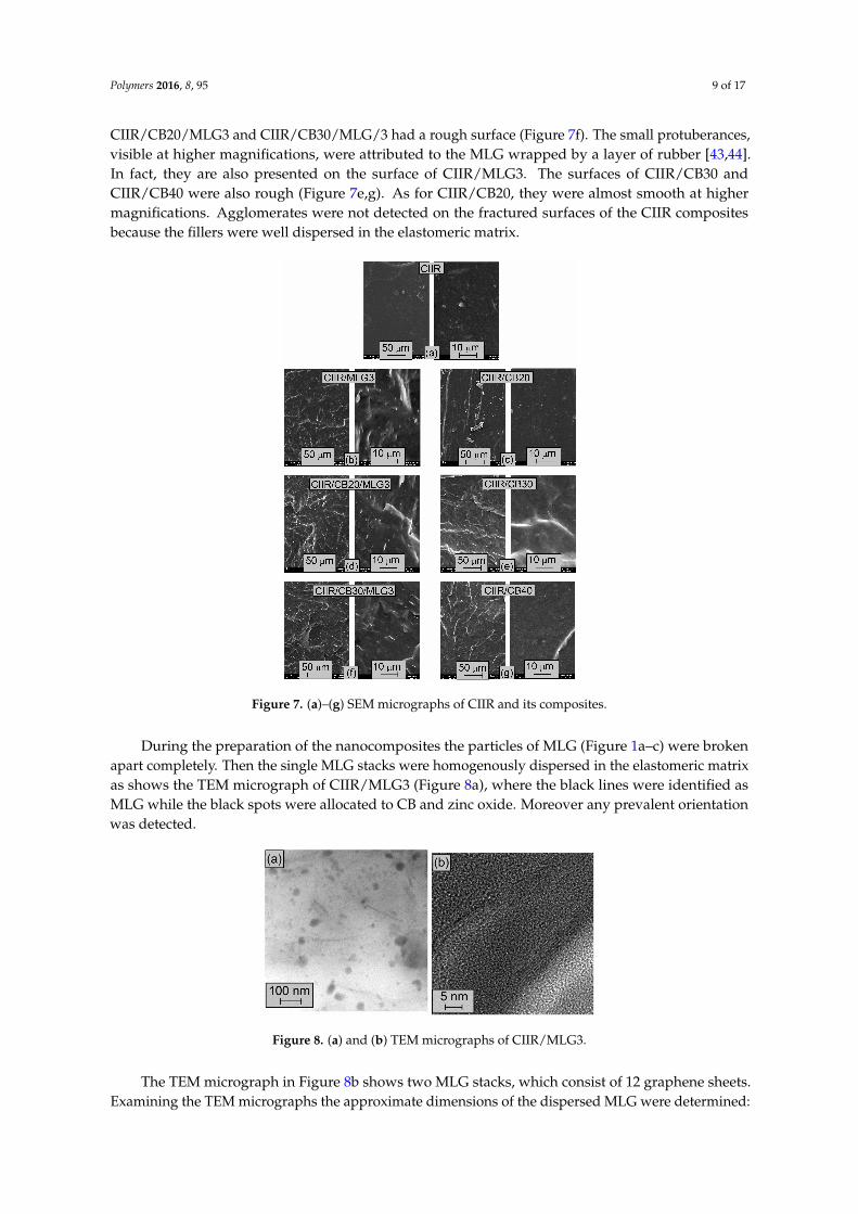
The curing curves of CIIR and its composites with MLG and CB are reported in Figure 6a. Vulcanization results in an increase of the torque over time. MLG and CB reinforced the torque and thus the curves of the filled compound were higher than CIIR.
Figure 6b reports the maximum of torque (MH) as a function of the filler content. MH is a measure of the stock modulus of the cured compounds [39]. Adding 3 phr MLG increases the MH of the composites by 1 to 2 dNm. Adding 3 phr MLG increased the MH of CIIR as much as 16 phr CB. In the presence of 20 and 30 phr CB, the reinforcing effect of 3 phr MLG was similar to 12 phr CB.
Figure 6c shows the minimum of the torque (ML) as a function of the filler loading. ML is a measure of the viscosity of the uncured compounds [40]. Adding 3 phr MLG increased the ML of CIIR by 14 %, which matched the effect of 10 phr CB. A similar effect was recorded in the presence of 20 phr CB. In the case of CIIR/CB30/MLG3, the nanofiller reinforced like 8 phr CB.
The difference between MH and ML (ΔS) is usually assumed to be proportional to the cross-link density [41,42]. ΔS is plotted as function of the filler content in Figure 6d. Adding 3 phr MLG increased ΔS by 1 to 1.4 dNm. As for MH, the effect of 3 phr MLG in CIIR/MLG was similar to 16 phr CB. The presence of 20 and 30 phr CB in CIIR/MLG/CB nanocomposite showed the same effect as adding an additional 12 phr CB. The curing properties of CIIR and its composites are summarized in Table 3.
Figure 5. (a) Storage modulus as a function of the strain amplitude of CIIR and its composites;and (b) difference between initial and final storage modulus as a function of the filler content; the lineis a visual guide.
Figure 5b reports the difference between the maximum and minimum of G1 as a function of thefiller content. ∆G1 of CIIR/MLG3 was 136 kPa, which is in correspondence with 23 phr CB. Adding3 phr MLG/20 phr CB shows the largest increase in ∆G (around 300 kPa) and thus reinforced ∆G1
as much as adding 32 phr CB; consequently the effect of 3 phr MLG was similar to 12 phr CB. In thepresence of 30 phr CB, the effect of 3 phr MLG corresponded to 7 phr CB. Due to the non-linearbehaviour of ∆G1 versus CB content, the efficiency of adding 3 phr MLG with respect to replacing CBdecreased markedly with higher CB content.
3.3. Curing Properties
The curing curves of CIIR and its composites with MLG and CB are reported in Figure 6a.Vulcanization results in an increase of the torque over time. MLG and CB reinforced the torque andthus the curves of the filled compound were higher than CIIR.
Figure 6b reports the maximum of torque (MH) as a function of the filler content. MH is a measureof the stock modulus of the cured compounds [39]. Adding 3 phr MLG increases the MH of thecomposites by 1 to 2 dNm. Adding 3 phr MLG increased the MH of CIIR as much as 16 phr CB. In thepresence of 20 and 30 phr CB, the reinforcing effect of 3 phr MLG was similar to 12 phr CB.
Polymers 2016, 8, 95 8 of 17Polymers 2016, 8, 95 8 of 16
Figure 6. (a) Curing curves of CIIR (chlorine isobutyl isoprene rubber) and its composites; (b) maximum of the torque; (c) minimum of the torque; and (d) difference between maximum and minimum of the torque as a function of the filler content; the lines are visual guides.
Table 3. Curing properties of CIIR and its composites.
ML (dNm) MH (dNm) ΔS (dNm) CIIR 0.75 ± 0.01 2.27 ± 0.01 1.52 ± 0.02
CIIR/MLG3 0.87 ± 0.03 3.34 ± 0.02 2.47 ± 0.05 CIIR/CB20 1.09 ± 0.06 3.82 ± 0.06 2.73 ± 0.01
CIIR/CB20/MLG3 1.43 ± 0.01 5.67 ± 0.01 4.25 ± 0.01 CIIR/CB30 1.42 ± 0.01 5.37 ± 0.01 3.95 ± 0.02
CIIR/CB30/MLG3 1.79 ± 0.10 7.11 ± 0.21 5.32 ± 0.11 CIIR/CB40 1.88 ± 0.04 7.06 ± 0.16 5.18 ± 0.20
3.4. Morphology of the CIIR and its Composites
Figure 7 shows the SEM micrographs of the freeze-fractured surface of CIIR and its composites. The surface of CIIR was smooth (Figure 7a). The incorporation of 3 phr MLG resulted in an increase in roughness of the surface of the investigated rubber (Figure 7b). In contrast, the surface of CIIR/CB20 presented few and large protuberances, but was completely smooth at high magnifications (Figure 7c). CIIR/CB20/MLG3 and CIIR/CB30/MLG/3 had a rough surface (Figures 7f). The small protuberances, visible at higher magnifications, were attributed to the MLG wrapped by a layer of rubber [43,44]. In fact, they are also presented on the surface of CIIR/MLG3. The surfaces of CIIR/CB30 and CIIR/CB40 were also rough (Figures 7e,g). As for CIIR/CB20, they were almost smooth at higher magnifications. Agglomerates were not detected on the fractured surfaces of the CIIR composites because the fillers were well dispersed in the elastomeric matrix.
During the preparation of the nanocomposites the particles of MLG (Figure 1a–c) were broken apart completely. Then the single MLG stacks were homogenously dispersed in the elastomeric matrix as shows the TEM micrograph of CIIR/MLG3 (Figure 8a), where the black lines were identified as MLG while the black spots were allocated to CB and zinc oxide. Moreover any prevalent orientation was detected.
Figure 6. (a) Curing curves of CIIR (chlorine isobutyl isoprene rubber) and its composites; (b) maximumof the torque; (c) minimum of the torque; and (d) difference between maximum and minimum of thetorque as a function of the filler content; the lines are visual guides.
Figure 6c shows the minimum of the torque (ML) as a function of the filler loading. ML is ameasure of the viscosity of the uncured compounds [40]. Adding 3 phr MLG increased the ML ofCIIR by 14 %, which matched the effect of 10 phr CB. A similar effect was recorded in the presence of20 phr CB. In the case of CIIR/CB30/MLG3, the nanofiller reinforced like 8 phr CB.
The difference between MH and ML (∆S) is usually assumed to be proportional to the cross-linkdensity [41,42]. ∆S is plotted as function of the filler content in Figure 6d. Adding 3 phr MLG increased∆S by 1 to 1.4 dNm. As for MH, the effect of 3 phr MLG in CIIR/MLG was similar to 16 phr CB.The presence of 20 and 30 phr CB in CIIR/MLG/CB nanocomposite showed the same effect as addingan additional 12 phr CB. The curing properties of CIIR and its composites are summarized in Table 3.
Table 3. Curing properties of CIIR and its composites.
ML (dNm) MH (dNm) ∆S (dNm)
CIIR 0.75 ˘ 0.01 2.27 ˘ 0.01 1.52 ˘ 0.02CIIR/MLG3 0.87 ˘ 0.03 3.34 ˘ 0.02 2.47 ˘ 0.05CIIR/CB20 1.09 ˘ 0.06 3.82 ˘ 0.06 2.73 ˘ 0.01
CIIR/CB20/MLG3 1.43 ˘ 0.01 5.67 ˘ 0.01 4.25 ˘ 0.01CIIR/CB30 1.42 ˘ 0.01 5.37 ˘ 0.01 3.95 ˘ 0.02
CIIR/CB30/MLG3 1.79 ˘ 0.10 7.11 ˘ 0.21 5.32 ˘ 0.11CIIR/CB40 1.88 ˘ 0.04 7.06 ˘ 0.16 5.18 ˘ 0.20
3.4. Morphology of the CIIR and its Composites
Figure 7 shows the SEM micrographs of the freeze-fractured surface of CIIR and its composites.The surface of CIIR was smooth (Figure 7a). The incorporation of 3 phr MLG resulted in an increase inroughness of the surface of the investigated rubber (Figure 7b). In contrast, the surface of CIIR/CB20presented few and large protuberances, but was completely smooth at high magnifications (Figure 7c).
Polymers 2016, 8, 95 9 of 17
CIIR/CB20/MLG3 and CIIR/CB30/MLG/3 had a rough surface (Figure 7f). The small protuberances,visible at higher magnifications, were attributed to the MLG wrapped by a layer of rubber [43,44].In fact, they are also presented on the surface of CIIR/MLG3. The surfaces of CIIR/CB30 andCIIR/CB40 were also rough (Figure 7e,g). As for CIIR/CB20, they were almost smooth at highermagnifications. Agglomerates were not detected on the fractured surfaces of the CIIR compositesbecause the fillers were well dispersed in the elastomeric matrix.
Polymers 2016, 8, 95 9 of 16
The TEM micrograph in Figure 8b shows two MLG stacks, which consist of 12 graphene sheets. Examining the TEM micrographs the approximate dimensions of the dispersed MLG were determined: 5 ± 2 nm of thickness and 170 ± 60 nm of width. Therefore the average aspect ratio of MLG in CIIR nanocomposite was 34.
Figure 7. (a)–(g) SEM micrographs of CIIR and its composites.
Figure 8. (a) and (b) TEM micrographs of CIIR/MLG3.
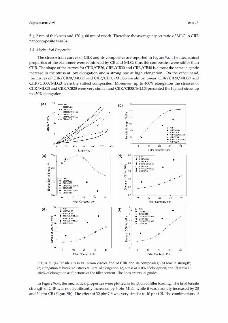
3.5. Mechanical Properties
The stress-strain curves of CIIR and its composites are reported in Figure 9a. The mechanical properties of the elastomer were reinforced by CB and MLG; thus the composites were stiffer than CIIR. The shape of the curves for CIIR/CB20, CIIR/CB30 and CIIR/CB40 is almost the same: a gentle increase in the stress at low elongation and a strong one at high elongation. On the other hand, the curves of CIIR/CB20/MLG3 and CIIR/CB30/MLG3 are almost linear. CIIR/CB20/MLG3 and CIIR/CB30/MLG3 were the stiffest composites. Moreover, up to 400% elongation the stresses of CIIR/MLG3 and CIIR/CB20 were very similar and CIIR/CB30/MLG3 presented the highest stress up to 450% elongation.
Figure 7. (a)–(g) SEM micrographs of CIIR and its composites.
During the preparation of the nanocomposites the particles of MLG (Figure 1a–c) were brokenapart completely. Then the single MLG stacks were homogenously dispersed in the elastomeric matrixas shows the TEM micrograph of CIIR/MLG3 (Figure 8a), where the black lines were identified asMLG while the black spots were allocated to CB and zinc oxide. Moreover any prevalent orientationwas detected.
Polymers 2016, 8, 95 9 of 16
The TEM micrograph in Figure 8b shows two MLG stacks, which consist of 12 graphene sheets. Examining the TEM micrographs the approximate dimensions of the dispersed MLG were determined: 5 ± 2 nm of thickness and 170 ± 60 nm of width. Therefore the average aspect ratio of MLG in CIIR nanocomposite was 34.
Figure 7. (a)–(g) SEM micrographs of CIIR and its composites.
Figure 8. (a) and (b) TEM micrographs of CIIR/MLG3.
3.5. Mechanical Properties
The stress-strain curves of CIIR and its composites are reported in Figure 9a. The mechanical properties of the elastomer were reinforced by CB and MLG; thus the composites were stiffer than CIIR. The shape of the curves for CIIR/CB20, CIIR/CB30 and CIIR/CB40 is almost the same: a gentle increase in the stress at low elongation and a strong one at high elongation. On the other hand, the curves of CIIR/CB20/MLG3 and CIIR/CB30/MLG3 are almost linear. CIIR/CB20/MLG3 and CIIR/CB30/MLG3 were the stiffest composites. Moreover, up to 400% elongation the stresses of CIIR/MLG3 and CIIR/CB20 were very similar and CIIR/CB30/MLG3 presented the highest stress up to 450% elongation.
Figure 8. (a) and (b) TEM micrographs of CIIR/MLG3.
The TEM micrograph in Figure 8b shows two MLG stacks, which consist of 12 graphene sheets.Examining the TEM micrographs the approximate dimensions of the dispersed MLG were determined:
Polymers 2016, 8, 95 10 of 17
5 ˘ 2 nm of thickness and 170 ˘ 60 nm of width. Therefore the average aspect ratio of MLG in CIIRnanocomposite was 34.
3.5. Mechanical Properties
The stress-strain curves of CIIR and its composites are reported in Figure 9a. The mechanicalproperties of the elastomer were reinforced by CB and MLG; thus the composites were stiffer thanCIIR. The shape of the curves for CIIR/CB20, CIIR/CB30 and CIIR/CB40 is almost the same: a gentleincrease in the stress at low elongation and a strong one at high elongation. On the other hand,the curves of CIIR/CB20/MLG3 and CIIR/CB30/MLG3 are almost linear. CIIR/CB20/MLG3 andCIIR/CB30/MLG3 were the stiffest composites. Moreover, up to 400% elongation the stresses ofCIIR/MLG3 and CIIR/CB20 were very similar and CIIR/CB30/MLG3 presented the highest stress upto 450% elongation.Polymers 2016, 8, 95 10 of 16
Figure 9. (a) Tensile stress vs. strain curves and of CIIR and its composites; (b) tensile strength; (c) elongation at break; (d) stress at 100% of elongation; (e) stress at 200% of elongation; and (f) stress at 300% of elongation as functions of the filler content. The lines are visual guides.
In Figure 9c–f, the mechanical properties were plotted as function of filler loading. The final tensile strength of CIIR was not significantly increased by 3 phr MLG, while it was strongly increased by 20 and 30 phr CB (Figure 9b). The effect of 30 phr CB was very similar to 40 phr CB. The combinations of CB and MLG also resulted in a higher tensile strength of CIIR, but this increase was lower than the effect of 20 phr CB. CIIR/CB20/MLG3 presented a tensile strength like a compound with 10 phr CB, while the combination of 30 phr CB and 3 phr MLG reinforced the tensile strength as much as about 15 phr CB.
Figure 9c shows the elongation at break as a function of the filler content. Adding 3 phr MLG and 20 phr CB resulted in a small increase in the final elongation, while the compounds with higher filler loading were more brittle. The reduction in elongation at break due to 3 phr MLG plus 20 phr CB was similar to that in composites with more than 50 phr CB. The strongest reduction was obtained with the simultaneous presence of 3 phr MLG and 30 CB. Based on a rough extrapolation, it was similar to more than 65 phr CB.
Figure 9. (a) Tensile stress vs. strain curves and of CIIR and its composites; (b) tensile strength;(c) elongation at break; (d) stress at 100% of elongation; (e) stress at 200% of elongation; and (f) stress at300% of elongation as functions of the filler content. The lines are visual guides.
In Figure 9c–f, the mechanical properties were plotted as function of filler loading. The final tensilestrength of CIIR was not significantly increased by 3 phr MLG, while it was strongly increased by 20and 30 phr CB (Figure 9b). The effect of 30 phr CB was very similar to 40 phr CB. The combinations of
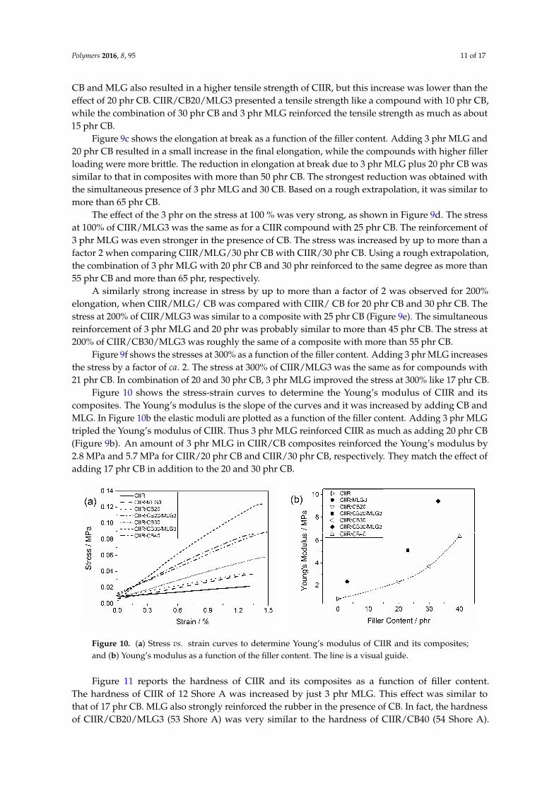
Polymers 2016, 8, 95 11 of 17
CB and MLG also resulted in a higher tensile strength of CIIR, but this increase was lower than theeffect of 20 phr CB. CIIR/CB20/MLG3 presented a tensile strength like a compound with 10 phr CB,while the combination of 30 phr CB and 3 phr MLG reinforced the tensile strength as much as about15 phr CB.
Figure 9c shows the elongation at break as a function of the filler content. Adding 3 phr MLG and20 phr CB resulted in a small increase in the final elongation, while the compounds with higher fillerloading were more brittle. The reduction in elongation at break due to 3 phr MLG plus 20 phr CB wassimilar to that in composites with more than 50 phr CB. The strongest reduction was obtained withthe simultaneous presence of 3 phr MLG and 30 CB. Based on a rough extrapolation, it was similar tomore than 65 phr CB.
The effect of the 3 phr on the stress at 100 % was very strong, as shown in Figure 9d. The stressat 100% of CIIR/MLG3 was the same as for a CIIR compound with 25 phr CB. The reinforcement of3 phr MLG was even stronger in the presence of CB. The stress was increased by up to more than afactor 2 when comparing CIIR/MLG/30 phr CB with CIIR/30 phr CB. Using a rough extrapolation,the combination of 3 phr MLG with 20 phr CB and 30 phr reinforced to the same degree as more than55 phr CB and more than 65 phr, respectively.
A similarly strong increase in stress by up to more than a factor of 2 was observed for 200%elongation, when CIIR/MLG/ CB was compared with CIIR/ CB for 20 phr CB and 30 phr CB. Thestress at 200% of CIIR/MLG3 was similar to a composite with 25 phr CB (Figure 9e). The simultaneousreinforcement of 3 phr MLG and 20 phr was probably similar to more than 45 phr CB. The stress at200% of CIIR/CB30/MLG3 was roughly the same of a composite with more than 55 phr CB.
Figure 9f shows the stresses at 300% as a function of the filler content. Adding 3 phr MLG increasesthe stress by a factor of ca. 2. The stress at 300% of CIIR/MLG3 was the same as for compounds with21 phr CB. In combination of 20 and 30 phr CB, 3 phr MLG improved the stress at 300% like 17 phr CB.
Figure 10 shows the stress-strain curves to determine the Young’s modulus of CIIR and itscomposites. The Young’s modulus is the slope of the curves and it was increased by adding CB andMLG. In Figure 10b the elastic moduli are plotted as a function of the filler content. Adding 3 phr MLGtripled the Young’s modulus of CIIR. Thus 3 phr MLG reinforced CIIR as much as adding 20 phr CB(Figure 9b). An amount of 3 phr MLG in CIIR/CB composites reinforced the Young’s modulus by2.8 MPa and 5.7 MPa for CIIR/20 phr CB and CIIR/30 phr CB, respectively. They match the effect ofadding 17 phr CB in addition to the 20 and 30 phr CB.
Polymers 2016, 8, 95 11 of 16
The effect of the 3 phr on the stress at 100 % was very strong, as shown in Figure 9d. The stress at 100% of CIIR/MLG3 was the same as for a CIIR compound with 25 phr CB. The reinforcement of 3 phr MLG was even stronger in the presence of CB. The stress was increased by up to more than a factor 2 when comparing CIIR/MLG/30 phr CB with CIIR/30 phr CB. Using a rough extrapolation, the combination of 3 phr MLG with 20 phr CB and 30 phr reinforced to the same degree as more than 55 phr CB and more than 65 phr, respectively.
A similarly strong increase in stress by up to more than a factor of 2 was observed for 200% elongation, when CIIR/MLG/ CB was compared with CIIR/ CB for 20 phr CB and 30 phr CB. The stress at 200% of CIIR/MLG3 was similar to a composite with 25 phr CB (Figure 9e). The simultaneous reinforcement of 3 phr MLG and 20 phr was probably similar to more than 45 phr CB. The stress at 200% of CIIR/CB30/MLG3 was roughly the same of a composite with more than 55 phr CB.
Figure 9f shows the stresses at 300% as a function of the filler content. Adding 3 phr MLG increases the stress by a factor of ca. 2. The stress at 300% of CIIR/MLG3 was the same as for compounds with 21 phr CB. In combination of 20 and 30 phr CB, 3 phr MLG improved the stress at 300% like 17 phr CB.
Figure 10 shows the stress-strain curves to determine the Young’s modulus of CIIR and its composites. The Young’s modulus is the slope of the curves and it was increased by adding CB and MLG. In Figure 10b the elastic moduli are plotted as a function of the filler content. Adding 3 phr MLG tripled the Young’s modulus of CIIR. Thus 3 phr MLG reinforced CIIR as much as adding 20 phr CB (Figure 9b). An amount of 3 phr MLG in CIIR/CB composites reinforced the Young’s modulus by 2.8 MPa and 5.7 MPa for CIIR/20 phr CB and CIIR/30 phr CB, respectively. They match the effect of adding 17 phr CB in addition to the 20 and 30 phr CB.
Figure 10. (a) Stress vs. strain curves to determine Young’s modulus of CIIR and its composites; and (b) Young’s modulus as a function of the filler content. The line is a visual guide.
Figure 11 reports the hardness of CIIR and its composites as a function of filler content. The hardness of CIIR of 12 Shore A was increased by just 3 phr MLG. This effect was similar to that of 17 phr CB. MLG also strongly reinforced the rubber in the presence of CB. In fact, the hardness of CIIR/CB20/MLG3 (53 Shore A) was very similar to the hardness of CIIR/CB40 (54 Shore A). The increase in Shore A hardness was linear with CB content and quite constant (13.8 ± 1.1) when adding 3 phr MLG. Hence, in the case of hardness, 3 phr MLG replaced about 20 phr CB in all of the nanocomposites. CIIR/CB30/MLG3 was the hardest compound. The mechanical properties of CIIR and its composites are summarized in Table 4.
Figure 10. (a) Stress vs. strain curves to determine Young’s modulus of CIIR and its composites;and (b) Young’s modulus as a function of the filler content. The line is a visual guide.
Figure 11 reports the hardness of CIIR and its composites as a function of filler content.The hardness of CIIR of 12 Shore A was increased by just 3 phr MLG. This effect was similar tothat of 17 phr CB. MLG also strongly reinforced the rubber in the presence of CB. In fact, the hardnessof CIIR/CB20/MLG3 (53 Shore A) was very similar to the hardness of CIIR/CB40 (54 Shore A).
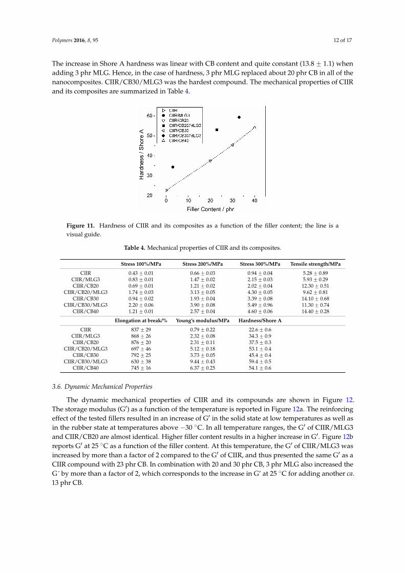
Polymers 2016, 8, 95 12 of 17
The increase in Shore A hardness was linear with CB content and quite constant (13.8 ˘ 1.1) whenadding 3 phr MLG. Hence, in the case of hardness, 3 phr MLG replaced about 20 phr CB in all of thenanocomposites. CIIR/CB30/MLG3 was the hardest compound. The mechanical properties of CIIRand its composites are summarized in Table 4.Polymers 2016, 8, 95 12 of 16
Figure 11. Hardness of CIIR and its composites as a function of the filler content; the line is a visual guide.
Table 4. Mechanical properties of CIIR and its composites.
Stress 100%/MPa Stress 200%/MPa Stress 300%/MPa Tensile strength/MPaCIIR 0.43 ± 0.01 0.66 ± 0.03 0.94 ± 0.04 5.28 ± 0.89
CIIR/MLG3 0.83 ± 0.01 1.47 ± 0.02 2.15 ± 0.03 5.93 ± 0.29 CIIR/CB20 0.69 ± 0.01 1.21 ± 0.02 2.02 ± 0.04 12.30 ± 0.51
CIIR/CB20/MLG3 1.74 ± 0.03 3.13 ± 0.05 4.30 ± 0.05 9.62 ± 0.81 CIIR/CB30 0.94 ± 0.02 1.93 ± 0.04 3.39 ± 0.08 14.10 ± 0.68
CIIR/CB30/MLG3 2.20 ± 0.06 3.90 ± 0.08 5.49 ± 0.96 11.30 ± 0.74 CIIR/CB40 1.21 ± 0.01 2.57 ± 0.04 4.60 ± 0.06 14.40 ± 0.28
Elongation at break/% Young’s modulus/MPa Hardness/Shore A CIIR 837 ± 29 0.79 ± 0.22 22.6 ± 0.6
CIIR/MLG3 868 ± 26 2.32 ± 0.08 34.3 ± 0.9 CIIR/CB20 876 ± 20 2.31 ± 0.11 37.5 ± 0.3
CIIR/CB20/MLG3 697 ± 46 5.12 ± 0.18 53.1 ± 0.4 CIIR/CB30 792 ± 25 3.73 ± 0.05 45.4 ± 0.4
CIIR/CB30/MLG3 630 ± 38 9.44 ± 0.43 59.4 ± 0.5 CIIR/CB40 745 ± 16 6.37 ± 0.25 54.1 ± 0.6
3.6. Dynamic Mechanical Properties
The dynamic mechanical properties of CIIR and its compounds are shown in Figure 12. The storage modulus (G′) as a function of the temperature is reported in Figure 12a. The reinforcing effect of the tested fillers resulted in an increase of G′ in the solid state at low temperatures as well as in the rubber state at temperatures above −30 °C. In all temperature ranges, the G′ of CIIR/MLG3 and CIIR/CB20 are almost identical. Higher filler content results in a higher increase in G′. Figure 12b reports G′ at 25 °C as a function of the filler content. At this temperature, the G′ of CIIR/MLG3 was increased by more than a factor of 2 compared to the G′ of CIIR, and thus presented the same G′ as a CIIR compound with 23 phr CB. In combination with 20 and 30 phr CB, 3 phr MLG also increased the G´ by more than a factor of 2, which corresponds to the increase in G’ at 25 °C for adding another ca. 13 phr CB.
Figure 12c reports the loss factor peak (tan δ of CIIR and its composites. The presence of fillers resulted in a reduction in the height of the peak because the fillers decreased the elastomeric chain mobility [45]. Strong rubber–filler interactions are the reasons for this behavior [46,47].
The maximum of tan δ as a function of the filler loading is reported in Figure 11d. The effect of 3 phr MLG was the same as of 16 phr CB. Adding 3 phr MLG reduced the maximum of tan δ of CIIR like 13 phr CB in the presence of 20 phr CB, while in the case of CIIR/CB30/MLG3, 3 phr MLG acted like 10 phr MLG.
Figure 11. Hardness of CIIR and its composites as a function of the filler content; the line is avisual guide.
Table 4. Mechanical properties of CIIR and its composites.
Stress 100%/MPa Stress 200%/MPa Stress 300%/MPa Tensile strength/MPa
CIIR 0.43 ˘ 0.01 0.66 ˘ 0.03 0.94 ˘ 0.04 5.28 ˘ 0.89CIIR/MLG3 0.83 ˘ 0.01 1.47 ˘ 0.02 2.15 ˘ 0.03 5.93 ˘ 0.29CIIR/CB20 0.69 ˘ 0.01 1.21 ˘ 0.02 2.02 ˘ 0.04 12.30 ˘ 0.51
CIIR/CB20/MLG3 1.74 ˘ 0.03 3.13 ˘ 0.05 4.30 ˘ 0.05 9.62 ˘ 0.81CIIR/CB30 0.94 ˘ 0.02 1.93 ˘ 0.04 3.39 ˘ 0.08 14.10 ˘ 0.68
CIIR/CB30/MLG3 2.20 ˘ 0.06 3.90 ˘ 0.08 5.49 ˘ 0.96 11.30 ˘ 0.74CIIR/CB40 1.21 ˘ 0.01 2.57 ˘ 0.04 4.60 ˘ 0.06 14.40 ˘ 0.28
Elongation at break/% Young’s modulus/MPa Hardness/Shore A
CIIR 837 ˘ 29 0.79 ˘ 0.22 22.6 ˘ 0.6CIIR/MLG3 868 ˘ 26 2.32 ˘ 0.08 34.3 ˘ 0.9CIIR/CB20 876 ˘ 20 2.31 ˘ 0.11 37.5 ˘ 0.3
CIIR/CB20/MLG3 697 ˘ 46 5.12 ˘ 0.18 53.1 ˘ 0.4CIIR/CB30 792 ˘ 25 3.73 ˘ 0.05 45.4 ˘ 0.4
CIIR/CB30/MLG3 630 ˘ 38 9.44 ˘ 0.43 59.4 ˘ 0.5CIIR/CB40 745 ˘ 16 6.37 ˘ 0.25 54.1 ˘ 0.6
3.6. Dynamic Mechanical Properties
The dynamic mechanical properties of CIIR and its compounds are shown in Figure 12.The storage modulus (G1) as a function of the temperature is reported in Figure 12a. The reinforcingeffect of the tested fillers resulted in an increase of G1 in the solid state at low temperatures as well asin the rubber state at temperatures above ´30 ˝C. In all temperature ranges, the G1 of CIIR/MLG3and CIIR/CB20 are almost identical. Higher filler content results in a higher increase in G1. Figure 12breports G1 at 25 ˝C as a function of the filler content. At this temperature, the G1 of CIIR/MLG3 wasincreased by more than a factor of 2 compared to the G1 of CIIR, and thus presented the same G1 as aCIIR compound with 23 phr CB. In combination with 20 and 30 phr CB, 3 phr MLG also increased theG´ by more than a factor of 2, which corresponds to the increase in G’ at 25 ˝C for adding another ca.13 phr CB.
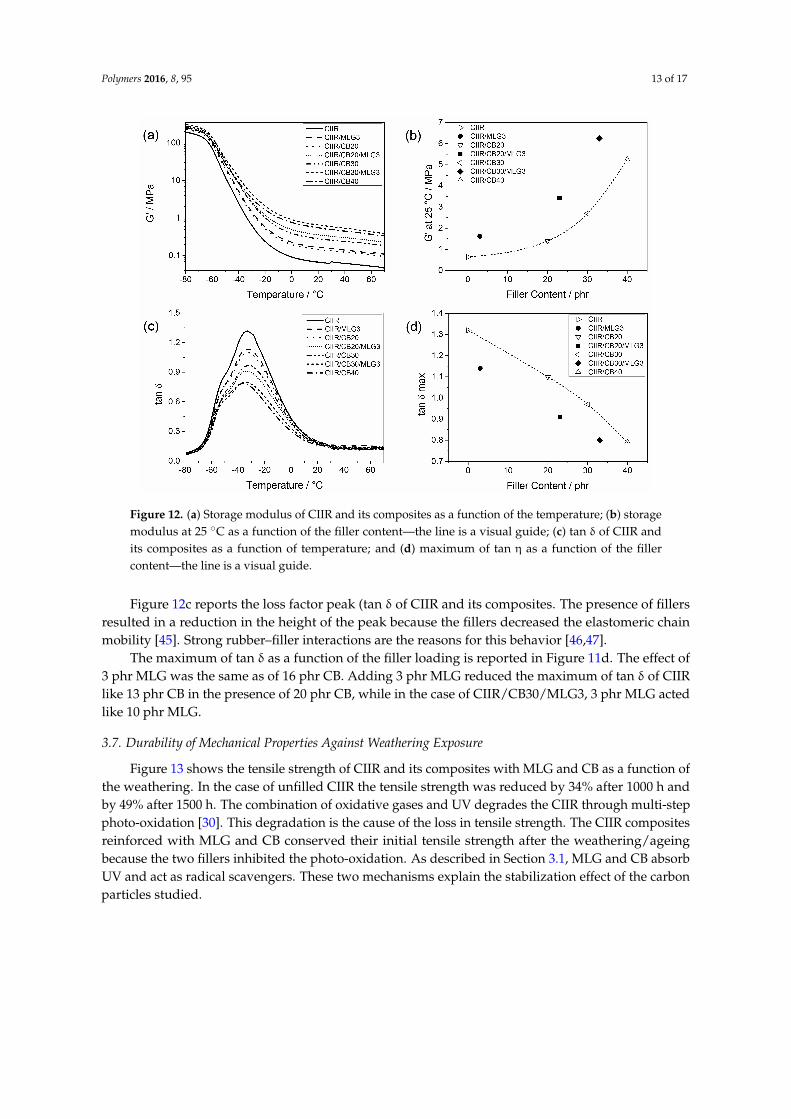
Polymers 2016, 8, 95 13 of 17Polymers 2016, 8, 95 13 of 16
Figure 12. (a) Storage modulus of CIIR and its composites as a function of the temperature; (b) storage modulus at 25 °C as a function of the filler content—the line is a visual guide; (c) tan δ of CIIR and its composites as a function of temperature; and (d) maximum of tan η as a function of the filler content—the line is a visual guide.
3.7. Durability of Mechanical Properties Against Weathering Exposure
Figure 13 shows the tensile strength of CIIR and its composites with MLG and CB as a function of the weathering. In the case of unfilled CIIR the tensile strength was reduced by 34% after 1000 h and by 49% after 1500 h. The combination of oxidative gases and UV degrades the CIIR through multi-step photo-oxidation [30]. This degradation is the cause of the loss in tensile strength. The CIIR composites reinforced with MLG and CB conserved their initial tensile strength after the weathering/ageing because the two fillers inhibited the photo-oxidation. As described in Section 3.1, MLG and CB absorb UV and act as radical scavengers. These two mechanisms explain the stabilization effect of the carbon particles studied.
Figure 13. Tensile strength of CIIR and its composites as a function of the weathering/exposure duration time. The lines are visual guides.
Figure 12. (a) Storage modulus of CIIR and its composites as a function of the temperature; (b) storagemodulus at 25 ˝C as a function of the filler content—the line is a visual guide; (c) tan δ of CIIR andits composites as a function of temperature; and (d) maximum of tan η as a function of the fillercontent—the line is a visual guide.
Figure 12c reports the loss factor peak (tan δ of CIIR and its composites. The presence of fillersresulted in a reduction in the height of the peak because the fillers decreased the elastomeric chainmobility [45]. Strong rubber–filler interactions are the reasons for this behavior [46,47].
The maximum of tan δ as a function of the filler loading is reported in Figure 11d. The effect of3 phr MLG was the same as of 16 phr CB. Adding 3 phr MLG reduced the maximum of tan δ of CIIRlike 13 phr CB in the presence of 20 phr CB, while in the case of CIIR/CB30/MLG3, 3 phr MLG actedlike 10 phr MLG.
3.7. Durability of Mechanical Properties Against Weathering Exposure
Figure 13 shows the tensile strength of CIIR and its composites with MLG and CB as a function ofthe weathering. In the case of unfilled CIIR the tensile strength was reduced by 34% after 1000 h andby 49% after 1500 h. The combination of oxidative gases and UV degrades the CIIR through multi-stepphoto-oxidation [30]. This degradation is the cause of the loss in tensile strength. The CIIR compositesreinforced with MLG and CB conserved their initial tensile strength after the weathering/ageingbecause the two fillers inhibited the photo-oxidation. As described in Section 3.1, MLG and CB absorbUV and act as radical scavengers. These two mechanisms explain the stabilization effect of the carbonparticles studied.
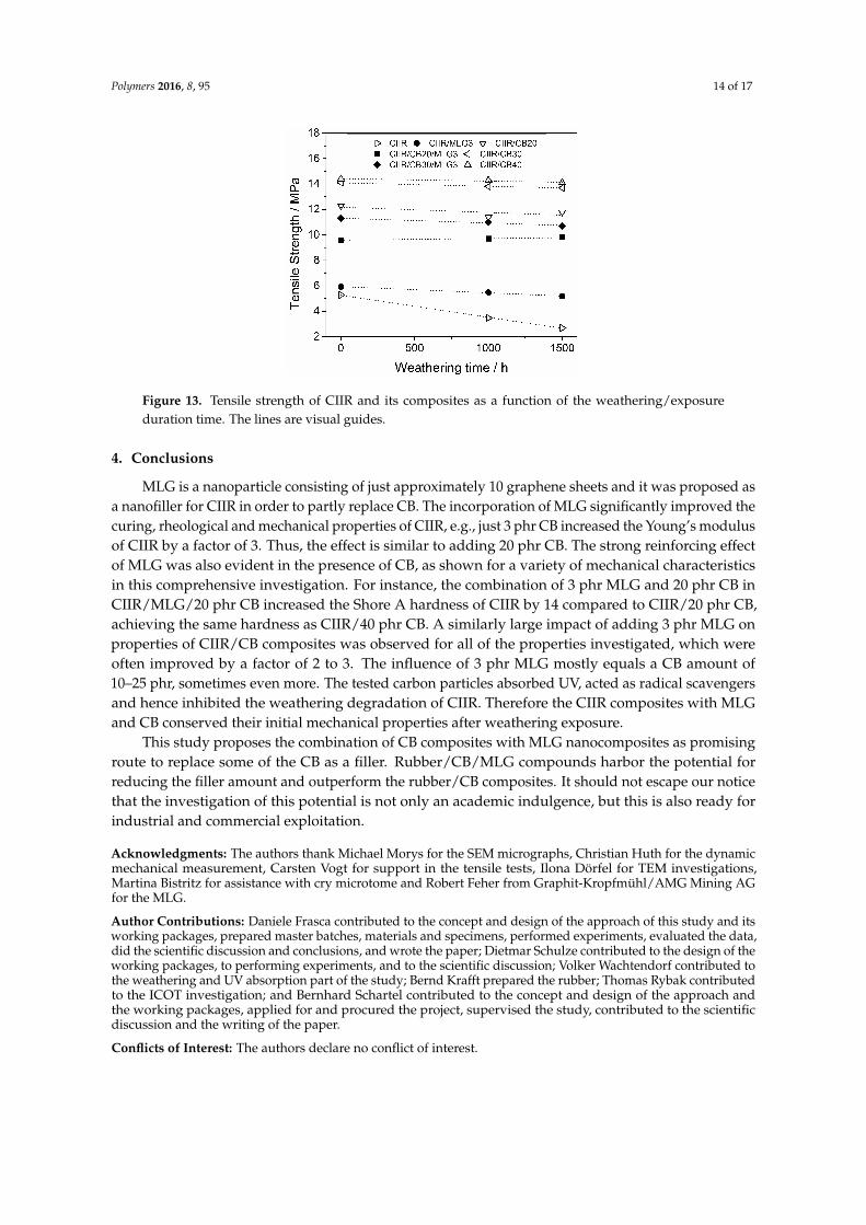
Polymers 2016, 8, 95 14 of 17
Polymers 2016, 8, 95 13 of 16
Figure 12. (a) Storage modulus of CIIR and its composites as a function of the temperature; (b) storage modulus at 25 °C as a function of the filler content—the line is a visual guide; (c) tan δ of CIIR and its composites as a function of temperature; and (d) maximum of tan η as a function of the filler content—the line is a visual guide.
3.7. Durability of Mechanical Properties Against Weathering Exposure
Figure 13 shows the tensile strength of CIIR and its composites with MLG and CB as a function of the weathering. In the case of unfilled CIIR the tensile strength was reduced by 34% after 1000 h and by 49% after 1500 h. The combination of oxidative gases and UV degrades the CIIR through multi-step photo-oxidation [30]. This degradation is the cause of the loss in tensile strength. The CIIR composites reinforced with MLG and CB conserved their initial tensile strength after the weathering/ageing because the two fillers inhibited the photo-oxidation. As described in Section 3.1, MLG and CB absorb UV and act as radical scavengers. These two mechanisms explain the stabilization effect of the carbon particles studied.
Figure 13. Tensile strength of CIIR and its composites as a function of the weathering/exposure duration time. The lines are visual guides. Figure 13. Tensile strength of CIIR and its composites as a function of the weathering/exposureduration time. The lines are visual guides.
4. Conclusions
MLG is a nanoparticle consisting of just approximately 10 graphene sheets and it was proposed asa nanofiller for CIIR in order to partly replace CB. The incorporation of MLG significantly improved thecuring, rheological and mechanical properties of CIIR, e.g., just 3 phr CB increased the Young’s modulusof CIIR by a factor of 3. Thus, the effect is similar to adding 20 phr CB. The strong reinforcing effectof MLG was also evident in the presence of CB, as shown for a variety of mechanical characteristicsin this comprehensive investigation. For instance, the combination of 3 phr MLG and 20 phr CB inCIIR/MLG/20 phr CB increased the Shore A hardness of CIIR by 14 compared to CIIR/20 phr CB,achieving the same hardness as CIIR/40 phr CB. A similarly large impact of adding 3 phr MLG onproperties of CIIR/CB composites was observed for all of the properties investigated, which wereoften improved by a factor of 2 to 3. The influence of 3 phr MLG mostly equals a CB amount of10–25 phr, sometimes even more. The tested carbon particles absorbed UV, acted as radical scavengersand hence inhibited the weathering degradation of CIIR. Therefore the CIIR composites with MLGand CB conserved their initial mechanical properties after weathering exposure.
This study proposes the combination of CB composites with MLG nanocomposites as promisingroute to replace some of the CB as a filler. Rubber/CB/MLG compounds harbor the potential forreducing the filler amount and outperform the rubber/CB composites. It should not escape our noticethat the investigation of this potential is not only an academic indulgence, but this is also ready forindustrial and commercial exploitation.
Acknowledgments: The authors thank Michael Morys for the SEM micrographs, Christian Huth for the dynamicmechanical measurement, Carsten Vogt for support in the tensile tests, Ilona Dörfel for TEM investigations,Martina Bistritz for assistance with cry microtome and Robert Feher from Graphit-Kropfmühl/AMG Mining AGfor the MLG.
Author Contributions: Daniele Frasca contributed to the concept and design of the approach of this study and itsworking packages, prepared master batches, materials and specimens, performed experiments, evaluated the data,did the scientific discussion and conclusions, and wrote the paper; Dietmar Schulze contributed to the design of theworking packages, to performing experiments, and to the scientific discussion; Volker Wachtendorf contributed tothe weathering and UV absorption part of the study; Bernd Krafft prepared the rubber; Thomas Rybak contributedto the ICOT investigation; and Bernhard Schartel contributed to the concept and design of the approach andthe working packages, applied for and procured the project, supervised the study, contributed to the scientificdiscussion and the writing of the paper.
Conflicts of Interest: The authors declare no conflict of interest.
Polymers 2016, 8, 95 15 of 17
References
1. Araby, S.; Meng, Q.; Zhang, L.; Zaman, I.; Mejewski, P.; Ma, J. Elastomeric composites based on carbonnanomaterials. Nanotechnology 2015, 26, 112001. [CrossRef] [PubMed]
2. Wolff, S. Chemical aspects of rubber reinforcement by fillers. Rubber Chem. Technol. 1996, 69, 325–346.[CrossRef]
3. Dannenberg, E.M. The effects of surface chemical interactions on the properties of filler-reinforced rubbers.Rubber Chem. Technol. 1975, 48, 410–444. [CrossRef]
4. Usuki, A.; Kojima, Y.; Kawasumi, M.; Okada, A.; Fukushima, Y.; Kurauchi, T.; Kamigaito, O. Synthesis ofnylon 6-clay hybrid. J. Mater. Res. 1993, 8, 1179–1184. [CrossRef]
5. Arroyo, M.; López-Manchado, M.A.; Herrero, B. Organo-montmorillonite as substitute of carbon black innatural rubber compounds. Polymer 2003, 44, 2447–2453. [CrossRef]
6. Conzatti, L.; Stagnaro, P.; Colucci, G.; Bongiovanni, R.; Priola, A.; Lostritto, A.; Galimberti, M. The claymineral modifier as the key to steer the properties of rubber nanocomposites. Appl. Clay Sci. 2012, 61, 14–21.[CrossRef]
7. Peng, C.-C.; Göpfert, A.; Drechsler, M.; Abetz, V. “Smart” silica-rubber nanocomposites in virtue of hydrogenbonding interaction. Polym. Adv. Technol. 2005, 16, 770–782. [CrossRef]
8. Gallo, E.; Schartel, B.; Schmaucks, G.; Von der Ehe, K.; Böhning, M. Effect of well dispersed amorphoussilicon dioxide in flame retarded styrene butadiene rubber. Plast. Rubber Compos. 2013, 42, 34–42. [CrossRef]
9. Peddini, S.K.; Bosnyak, C.P.; Henderson, N.M.; Ellison, C.J.; Paul, D.R. Nanocomposites fromstyrene-butadiene rubber (SBR) and multiwall carbon nanotubes (MWCNT) part 1: Morphology andrheology. Polymer 2014, 55, 258–270. [CrossRef]
10. Das, A.; Stöckelhuber, K.W.; Jurk, R.; Saphiannikova, M.; Fritzsche, J.; Lorenz, H.; Klüppel, M.; Heinrich, G.Modified and unmodified multiwalled carbon nanotubes in high performance solution-styrene-butadieneand butadiene rubber blends. Polymer 2008, 49, 5276–5283. [CrossRef]
11. Galimberti, M.; Coombs, M.; Cipolletti, V.; Spatola, A.; Guerra, G.; Lostritto, A.; Giannini, L.; Pandini, S.;Riccò, T. Delaminated and intercalated organically modified montmorillonite in poly(1,4-cis-isoprene) matrix.Indications of counterintuitive dynamic-mechanical behavior. Appl. Clay Sci. 2014, 97–98, 8–16. [CrossRef]
12. Galimberti, M.; Coombs, M.; Cipolletti, V.; Giannini, L.; Conzatti, L. The origin of synergism between anorganoclay and carbon black. Appl. Clay Sci. 2013, 83, 449–456. [CrossRef]
13. Galimberti, M.; Coombs, M.; Cipolletti, V.; Riccio, P.; Riccò, T.; Pandini, S.; Conzatti, L. Enhancement ofmechanical reinforcement due to hybrid filler networking promoted by an organoclay in hydrocarbon-basednanocomposites. Appl. Clay Sci. 2012, 65, 57–66. [CrossRef]
14. Forouharshad, M.; Gardella, L.; Furfaro, D.; Galimberti, M.; Monticelli, O. A low-environmental-impactapproach for novel bio-composites based on PLLA/PCL blends and high surface area graphite. Eur. Polym. J.2015, 70, 28–36. [CrossRef]
15. Lapa, V.L.D.C.; de Oliveira, P.D.; Visconte, L.L.Y.; Nunes, R.C.R. Investigation of NBR-cellulose iinanocomposites by rheometric and equilibrium swelling properties. Polym. Bull. 2008, 60, 281–290.[CrossRef]
16. Novoselov, K.S.; Geim, A.K.; Morozov, S.V.; Jiang, D.; Zhang, Y.; Dubonos, S.V.; Grigorieva, I.V.; Firsov, A.A.Electric field effect in atomically thin carbon films. Science 2004, 306, 666–669. [CrossRef] [PubMed]
17. Schopp, S.; Thomann, R.; Ratzsch, K.F.; Kerling, S.; Altstädt, V.; Mülhaupt, R. Functionalized grapheneand carbon materials as components of styrene-butadiene rubber nanocomposites prepared by aqueousdispersion blending. Macromol. Mater. Eng. 2014, 299, 319–329. [CrossRef]
18. Sadasivuni, K.K.; Ponnamma, D.; Thomas, S.; Grohens, Y. Evolution from graphite to graphene elastomercaposites. Prog. Polym. Sci. 2014, 39, 749–780. [CrossRef]
19. Lee, J.H.; Shin, D.W.; Makotchenko, V.G.; Nazarov, A.S.; Fedorov, V.E.; Yoo, J.H.; Yu, S.M.; Choi, J.-Y.;Kim, J.M.; Ji-Beom, Y. The superior dispersion of easily soluble graphite. Small 2010, 6, 58–62. [CrossRef][PubMed]
20. Boehm, H.P.; Clauss, A.; Fischer, G.O.; Hofmann, U. Das adsorptionsverhalten sehr dünner kohlenstoff-folien.Z. Anorg. Allg. Chem. 1962, 316, 119–127. [CrossRef]

Polymers 2016, 8, 95 16 of 17
21. Steurer, P.; Wissert, R.; Thomann, R.; Mülhaupt, R. Functionalized graphenes and thermoplasticnanocomposites based upon expanded graphite oxide. Macromol. Rapid Commun. 2009, 30, 316–327.[CrossRef] [PubMed]
22. Dittrich, B.; Wartig, K.A.; Hofmann, D.; Mülhaupt, R.; Schartel, B. The influence of layered, spherical, andtubular carbon nanomaterials’ concentration on the flame retardancy of polypropylene. Polym. Compos. 2015,36, 1230–1241. [CrossRef]
23. Dittrich, B.; Wartig, K.A.; Mülhaupt, R.; Schartel, B. Flame-retardancy properties of intumescent ammoniumpoly(phosphate) and mineral filler magnesium hydroxide in combination with graphene. Polymers 2014,6, 2875–2895. [CrossRef]
24. Dittrich, B.; Wartig, K.A.; Hofmann, D.; Mülhaupt, R.; Schartel, B. Carbon black, multiwall carbonnanotubes, expanded graphite and functionalized graphene flame retarded polypropylene nanocomposites.Polym. Adv. Technol. 2013, 24, 916–926. [CrossRef]
25. Dittrich, B.; Wartig, K.-A.; Hofmann, D.; Mülhaupt, R.; Schartel, B. Flame retardancy through carbonnanomaterials: Carbon black, multiwall nanotubes, expanded graphite, multi-layer graphene and graphenein polypropylene. Polym. Degrad. Stab. 2013, 98, 1495–1505. [CrossRef]
26. Frasca, D.; Schulze, D.; Böhning, M.; Krafft, B.; Schartel, B. Multilayer graphene chlorine isobutyl isoprenerubber nanocomposites: Influence of the multilayer graphene concentration on physical and flame-retardantsproperties. Rubber Chem. Technol. 2016, in press. [CrossRef]
27. Frasca, D.; Schulze, D.; Wachtendorf, V.; Huth, C.; Schartel, B. Multifunctional multilayer graphene/elastomernanocomposites. Eur. Polym. J. 2015, 71, 99–113. [CrossRef]
28. Wu, J.; Huang, G.; Pan, Q.; Zheng, J.; Zhu, Y.; Wang, B. An investigation on the molecular mobility throughthe glass transition of chlorinated butyl rubber. Polymer 2007, 48, 7653–7659. [CrossRef]
29. Frasca, D.; Schulze, D.; Wachtendorf, V.; Morys, M.; Schartel, B. Multilayer graphene/chlorune-isobutene-isoprene rubber nanocomposites: Effect of the dispersion. Polym. Adv. Technol. 2016. in press. [CrossRef]
30. Mertz, G.; Hassouna, F.; Leclère, P.; Dahoun, A.; Toniazzo, V.; Ruch, D. Correlation between(nano)-mechanical and chemical changes occurring during photo-oxidation of filled vulcanised styrenebutadiene rubber (SBR). Polym. Degrad. Stab. 2012, 97, 2195–2201. [CrossRef]
31. Schröder, H.; Zeynalov, E.; Bahr, H.; Rybak, T. Analysing the content of antioxidants in pp materials.Polym. Polym. Compos. 2002, 10, 73–82.
32. Mensah, B.; Kumar, D.; Lim, D.-K.; Kim, S.G.; Jeong, B.-H.; Nah, C. Preparation and properties ofacrylonitrile–butadiene rubber–graphene nanocomposites. J. Appl. Polym. Sci. 2015, 132, 42457. [CrossRef]
33. Lai, Q.; Zhu, S.; Luo, X.; Zou, M.; Huang, S. Ultraviolet-visible spectroscopy of graphene oxides. Advances2012, 2, 032146. [CrossRef]
34. Jäger, C.; Henning, T.; Schlögl, R.; Spillecke, O. Spectral properties of carbon black. J. Non-Cryst. Solids 1999,258, 161–179. [CrossRef]
35. Zeynalov, E.B.; Allen, N.S.; Salmanova, N.I. Radical scavengering efficiency of different fullerenes c60–c70and fullerene soot. Polym. Degrad. Stab. 2009, 94, 1183–1189. [CrossRef]
36. Kumar, V.; Hanel, T.; Giannini, L.; Galimberti, M.; Giese, U. Graphene reinforced synthetic isoprene rubbernanocomposites. KGK 2014, 10.
37. Payne, A.R. The dynamic properties of carbon black-loaded natural rubber vulcanizates. J. Appl. Polym. Sci.1962, 6, 57–63. [CrossRef]
38. Fritzsche, J.; Lorenz, H.; Klüppel, M. CNT based elastomer-hybrid-nanocomposites with promisingmechanical and electrical properties. Macromol. Mater. Eng. 2009, 294, 551–560. [CrossRef]
39. Teh, P.L.; Mohd Ishak, Z.A.; Hashim, A.S.; Karger-Kocsis, J.; Ishiaku, U.S. Effects of epoxidized naturalrubber as a compatibilizer in melt compounded natural rubber–organoclay nanocomposites. Eur. Polym. J.2004, 40, 2513–2521. [CrossRef]
40. Malas, A.; Pal, P.; Das, C.K. Effect of expanded graphite and modified graphite flakes on the physicaland thermo-mechanical properties of styrene butadiene rubber/polybutadiene rubber (SBR/BR) blends.Mater. Des. 2014, 55, 664–673. [CrossRef]
41. Ismail, H.; Chia, H.H. The effects of multifunctional additive and epoxidation in silica filled natural rubbercompounds. Polym. Test. 1998, 17, 199–210. [CrossRef]
42. Ismail, H.; Chia, H.H. The effects of multifunctional additive and vulcanization systems on silica filledepoxidized natural rubber compounds. Eur. Polym. J. 1998, 34, 1857–1863. [CrossRef]
Polymers 2016, 8, 95 17 of 17
43. Xing, W.; Wu, J.; Huang, G.; Li, H.; Tang, M.; Fu, X. Enhanced mechanical properties of graphene/naturalrubber nanocomposites at low content. Polym. Int. 2014, 63, 1674–1681. [CrossRef]
44. Kang, H.; Zuo, K.; Wang, Z.; Zhang, L.; Liu, L.; Guo, B. Using a green method to develop grapheneoxide/elastomers nanocomposites with combination of high barrier and mechanical performance.Compos. Sci. Technol. 2014, 92, 1–8. [CrossRef]
45. Menes, O.; Cano, M.; Benedito, A.; Giménez, E.; Castell, P.; Maser, W.K.; Benito, A.M. The effect of ultra-thingraphite on the morphology and physical properties of thermoplastic polyurethane elastomer composites.Compos. Sci. Technol. 2012, 72, 1595–1601. [CrossRef]
46. Das, A.; Kasaliwal, G.R.; Jurk, R.; Boldt, R.; Fischer, D.; Stöckelhuber, K.W.; Heinrich, G. Rubbercomposites based on graphene nanoplatelets, expanded graphite, carbon nanotubes and their combination:A comparative study. Compos. Sci. Technol. 2012, 72, 1961–1967. [CrossRef]
47. Poikelispää, M.; Das, A.; Dierkes, W.; Vuorinen, J. The effect of partial replacement of carbon black by carbonnanotubes on the properties of natural rubber/butadiene rubber compound. J. Appl. Polym. Sci. 2013,130, 3153–3160. [CrossRef]
© 2016 by the authors; licensee MDPI, Basel, Switzerland. This article is an open accessarticle distributed under the terms and conditions of the Creative Commons by Attribution(CC-BY) license (http://creativecommons.org/licenses/by/4.0/).
89
4. Summary and Outlook
MLG is a commercially available nanoparticle and it is made of just approximately 10
graphene sheets. In this study it was successfully proposed as nanofiller for rubber
nanocomposites and it is ready for a large scale investigation. Only 3 phr of well dispersed
MLG improved clearly the performances of the tested elastomers in presence and absence of
CB.
Initially CIIR/MLG nanocomposites with the same MLG loading (3 phr) were
prepared by means of melt compounding in a two-roll mill, and by an ultrasonically-assisted
solution mixing procedure followed by two-roll milling. Rheological measurements, TEM
and SEM micrographs showed that the dispersion of MLG was better in the nanocomposites
produced via solution. The well dispersed MLG resulted in a high reinforcement in
mechanical and curing properties. Beyond the reinforcing effect, the well dispersed MLG
showed a protective effect against weathering exposure. In fact the nanocomposites prepared
via solution conserved their mechanical properties after weathering exposure. Moreover, ΔS,
determined by the curing curves, was proposed as a measure of the dispersion of nanofiller in
rubber compounds.
The solution mixing was used to prepare CIIR/MLG nanocomposites with different
MLG contents. The high reinforcing effect of the tested nanofiller was evident already at the
lowest loading. Just 3 phr of MLG increased clearly the rheological, mechanical, and curing
properties compared to the unfilled rubber. Moreover, MLG strongly improved the functional
properties of the CIIR: gas impermeability, electrical and thermal conductivities. The increase
in thermal conductivity resulted in an increase in the time of ignition. During combustion,
MLG formed a protective layer which resulted in improvement to the burning properties.
Higher MLG loadings yielded a further improvement in the final properties of the
nanocomposites. The comparison between experimental data (Young’s modulus and gas
90
permeability) and theoretical models provided the estimated values of aspect ratio of MLG
which were absolutely concordant with the TEM analysis.
The high reinforcing effect was also investigated in others popular rubbers: NR, NBR
and SBR. Thus nanocomposites with 3 phr MLG were prepared through the solution mixing
procedure followed by two-roll milling. In any rubber, MLG was well dispersed and
improved rheological, curing and mechanical properties. Moreover because of its chemical
structure, MLG absorbed UV and acted as radical scavenger, inhibiting the photo degradation
of the elastomeric matrix. Consequently, the nanocomposites conserved their mechanical
properties after weathering exposure.
In the case of CIIR, 3 phr MLG tripled the Young’s modulus as 20 phr of CB. The
strong reinforcing effect of MLG was also evident in the presence of CB. For instance, the
combination of 3 phr MLG and 20 phr CB achieved the same Shore A hardness of 40 phr CB.
In all the investigated properties, the influence of 3 phr MLG was mostly equivalent to a CB
content of 10 – 25 phr, sometimes even more. The studied carbon particles absorbed UV,
acted as radical scavengers and consequently inhibited the photo degradation of CIIR. Thus
the CIIR composites with MLG and CB conserved their initial mechanical properties after
weathering exposure.
In the end, MLG is an efficient nanofiller for rubbers nanocomposites working already
at low content. 3 phr of well dispersed MLG improved clearly the curing, rheological,
mechanical and functional properties of the investigated rubber. Moreover the reinforcing
effect of 3 phr MLG was similar of 10 – 25 phr of CB. Moreover MLG protected the
elastomeric matrices against the weathering exposure.
91
5. Zusammenfassung
Mehrschichtiges Graphen (MLG) ist ein kommerziell verfügbarer Nanofuellstoff und
besteht aus nur ca. 10 Blättern Graphen. In dieser Arbeit wurde MLG erfolgreich als
Nanofüllmaterial für Elastomere eingefuehrt und weitreichende Untersuchung vorgenommen.
Bereits 3 phr gut verteiltes MLG verbesserte die Leistung der geprüften Elastomere, mit und
ohne Carbon Black (CB), deutlich.
Zuerst wurden Chlorbutyl Kautschuk (eng. Chlorine Isobutyl Isoprene Rubber (CIIR))
/MLG-Nanoverbundwerkstoffe mit 3 phr MLG auf zwei unterschiedlicher Arten hergestellt:
(i) nur mit einem Duo-Walzwerk, mit zwei parallelen Walzen (ii) mit Ultraschall-gestützten
Lösungsmischen gefolgt von dem Duo-Walzwerk. Rheologische Messungen, SEM und TEM
Aufnahmen zeigten eine bessere MLG-Dispersion in dem lösungsgemischten
Nanoverbundwerkstoff. Gut verteiltes MLG fuehrte zu einer deutlichen Verbesserung der
Vulkanisations- und mechanischen Eigenschaften. Zusaetzlich zum Verstärkungseffekt wies
gut verteiltes MLG einen Schutzeffekt gegen Bewitterung auf. Tatsaechlich behielten die
lösungsgemischten Nanoverbundwerkstoffe ihre mechanischen Eigenschaften nach der
Bewitterung bei. Außerdem wurde ΔS (bestimmet durch die Vulkanisationskurven) als
Maßeinheit fuer die Dispersion des Nanofüllstoffes in der Gummimischung eingefuehrt.
Anschliessend wurde die erprobte Vorgehensweise mittels Lösungsmischens auch für
die Herstellung einer Konzentrationsreihe von CIIR/MLG-Nanoverbundwerkstoffe mit
unterschiedlicher MLG-Konzentration verwendet. Bereits bei geringer Füllstoffkonzentration
war MLG ein hocheffizientes Nanofüllmaterial für CIIR. Bereits die niedrigste MLG-
Konzentration von 3 phr hat zu einer deutlichen Verbesserung der rheologisch,
Vulkanisations- und mechanisch Eigenschaften gefuegrt. Zudem verstaertkte MLG nachhaltig
die funktionellen Eigenschaften (Gaspermeation, elektrische Leitfähigkeit und
Wärmeleitfähigkeit) von CIIR. Die Erhöhung der Wärmeleitfähigkeit fuehrte zu einer
92
Verzoegerung der Zündzeit. Waehrend eines Brandes bildete MLG eine Schutzschicht aus
und verbesserte dadurch das Abbrandverhalten. Der Vergleich von experimentellen Daten
(Elastizitätsmodul und Gaspermeation) mit den theoretischen Modellen lieferte geschätzten
Werte des Seitenverhältnisses von MLG, die mit der TEM-Analyse uebereinstimmten.
Der festgestellte Verstärkungseffekt wurde auch in anderen weitverwendeten
Gummisorten untersucht: Naturkautschuk (eng. Natural Rubber (NR)), Nitril-
Butadienkautschuk (eng. Nitrile Butadiene Rubber (NBR)) und Styrol-Butadienkautschuk
(eng. Styrene Butadiene Rubber (SBR). Auch diese Nanoverbundwerkstoffe wurden aufgrund
der besseren MLG-Dispersion mittels Lösungsmischen mit anschließender Bearbeitung im
Duo-Walzwerk mit einer Konzentration von 3 phr MLG herstellet. Bei allen Mischungen war
MLG gut verteilt und verbesserte die Vulkanisations-, rheologischen und mechanischen
Eigenschaften. Aufgrund seiner chemischen Struktur absorbierte MLG die UV-Strahlung,
wirkte gleichzeitig als Radikalfänger und schränkte den photochemischen Abbau der
Elastomermatrix ein. Folglich behielten die Nanoverbundwerkstoffe ihre mechanischen
Eigenschaften nach der Bewitterung bei.
3 phr MLG hat wie auch 20 phr CB den Elastizitätsmodul von CIIR verdreifacht. Der
Verstärkungseffekt des MLG war auch in Gegenwart von CB ersichtlich: Zum Beispiel zeigte
die Kombination von 3 phr MLG und 20 phr CB die gleiche Härte wie die Mischung mit 40
phr CB. In allen untersuchten Eigenschaften war der Effekt von 3 phr MLG äquivalent zu 10
– 25 phr CB, manchmal sogar noch mehr. Wie auch MLG adsorbierte CB die UV Strahlung,
wirkten als Radikalfänger und schränkten folglich den photochemischer Abbau von CIIR ein.
Somit konnte nach der Bewitterung der CIIR/CB/MLG-Verbundwerkstoffe kein Verlust ihrer
mechanischen Eigenschaften festgestellt werden.
Letztlich ist MLG ein hocheffizientes Nanofüllmaterial für Gummis schon bei
geringer Füllstoffkonzentration. 3 phr an gut verteiltem MLG verbesserte die rheologischen,

93
Vulkanisations-, mechanischen und funktionellen Eigenschaften der untersuchten Gummis
deutlich.

94
6. References
1. Ciullo, P.A.; Hewitt, N. The rubber formulary. Noyes Publications/William Andrew
Publishing, LLC: Norwich, New York, USA, 1999.
2. Cataldo, F. Introduzione alla chimica macromolecolare: Chimica della gomma e delle
materie plastiche. Lupi: Roma, IT, 1994.
3. Ciesielski, A. An introduction to rubber technoloy. Rapra Technology Limited:
Shawbury, Shrewsbury, Shropshire, SY4 4NR, UK, 1999.
4. Sperling, L.H. Cross-linked polymers and rubber elasticity. In Introduction to physical
polymer science, 4th edition, John Wiley & Sons Ltd: Hoboken, New Jersey, 2006.
5. Ghosh, P.; Katare, S.; Patkar, P.; Caruthers, J.M.; Venkatasubramanian, V.; Walker,
K.A. Sulfur vulcanization of natural rubber for benzothiazole accelerated
formulations: From reaction mechanisms to a rational kinetic model. Rubber Chem.
Technol. 2003, 76, 592-693.
6. Wu, J.; Xing, W.; Huang, G.; Li, H.; Tang, M.; Wu, S.; Liu, Y. Vulcanization kinetics
of graphene/natural rubber nanocomposites. Polymer 2013, 54, 3314-3323.
7. Wolff, S. Chemical aspects of rubber reinforcement by fillers. Rubber Chem. Technol.
1996, 69, 325-346.
8. Dannenberg, E.M. The effects of surface chemical interactions on the properties of
filler-reinforced rubbers. Rubber Chem. Technol. 1975, 48, 410-444.
9. Schartel, B.; Wendorff, J.H. Molecular composites for molecular reinforcement: A
promising concept between success and failure. Polym. Eng. Sci. 1999, 39, 128-151.
10. Araby, S.; Meng, Q.; Zhang, L.; Zaman, I.; Mejewski, P.; Ma, J. Elastomeric
composites based on carbon nanomaterials. Nanotechnology 2015, 26, 112001.
11. Rosamma, A. Nanofillers in rubber-rubber blends. In Rubber nanocomposites:
Preparation, properties and applications, Sabu, T.; Ranimol, S., Eds. John Wiley &
Sons Ltd: Chichester, U.K., 2010.
12. Jun, M.; Li Qun, Z.; Li, G. Manufacturing techniques of rubber nanocomposites. In
Rubber nanocomposites: Preparation, properties and applications, Sabu, T.; Ranimol,
S., Eds. John Wiley & Sons Ltd: Chichester, U.K., 2010.
13. Kuilla, T.; Bhadra, S.; Yao, D.; Kim, N.H.; Bose, S.; Lee, J.H. Recent advances in
graphene based polymer composites. Prog. Polym. Sci. 2010, 35, 1350-1375.
95
14. Ward, I.M.; Hadley, D.W. Polymer composites: Macroscale and microscale. In An
introduction to the mechanical properties of solid polymers, John Wiley & Sons Ltd:
Chichester, U.K., 1993.
15. Usuki, A.; Kojima, Y.; Kawasumi, M.; Okada, A.; Fukushima, Y.; Kurauchi, T.;
Kamigaito, O. Synthesis of nylon 6-clay hybrid. J. Mater. Res. 1993, 8, 1179-1184.
16. Gatos, K.G.; Karger-Kocsis, J. Rubber/clay nanocomposites: Preparation, properties
and applications. In Rubber nanocomposites: Preparation, properties and
applications,, Sabu, T.; Ranimol, S., Eds. John Wiley & Sons Ltd: Chichester, U.K.,
2010.
17. Manias, E.; Touny, A.; Wu, L.; Strawhecker, K.; Lu, B.; Chung, T.C.
Polypropylene/montmorillonite nanocomposites. Review of the synthetic routes and
materials properties. Chem. Mater. 2001, 13, 3516-3523.
18. Okamoto, M. Polymer/layered filler nanocompositees: An overview from science and
technology. In Macromolecular engineering: Precise synthesis, materials properties,
applications, 4 volume, Matyjaszewski, K.; Gnanou, Y.; Leibler, L., Eds. Wiley-VCH
Verlag GmbH & Co. KGaA: Weinheim, Germany, 2007.
19. Galimberti, M.; Coombs, M.; Cipolletti, V.; Riccio, P.; Riccò, T.; Pandini, S.;
Conzatti, L. Enhancement of mechanical reinforcement due to hybrid filler networking
promoted by an organoclay in hydrocarbon-based nanocomposites. Appl. Clay Sci.
2012, 65-66, 57-66.
20. Galimberti, M.; Coombs, M.; Cipolletti, V.; Giannini, L.; Conzatti, L. The origin of
synergism between an organoclay and carbon black. Appl. Clay Sci. 2013, 83-84, 449-
456.
21. Galimberti, M.; Coombs, M.; Cipolletti, V.; Spatola, A.; Guerra, G.; Lostritto, A.;
Giannini, L.; Pandini, S.; Riccò, T. Delaminated and intercalated organically modified
montmorillonite in poly(1,4-cis-isoprene) matrix. Indications of counterintuitive
dynamic-mechanical behavior. Appl. Clay Sci. 2014, 97-98, 8-16.
22. Komori, Y.; Kuroda, K. Layered silicate-polymer intercalation compounds. In
Polymer-clay nanocomposites, Pinnavia, T.J.; Beall, G.W., Eds. John Wiley & Sons
Ltd.: Chichester, U.K., 2000.
23. Das, A.; Stöckelhuber, K.W.; Jurk, R.; Saphiannikova, M.; Fritzsche, J.; Lorenz, H.;
Klüppel, M.; Heinrich, G. Modified and unmodified multiwalled carbon nanotubes in
96
high performance solution-styrene–butadiene and butadiene rubber blends. Polymer
2008, 49, 5276-5283.
24. Dittrich, B.; Wartig, K.A.; Hofmann, D.; Mülhaupt, R.; Schartel, B. Carbon black,
multiwall carbon nanotubes, expanded graphite and functionalized graphene flame
retarded polypropylene nanocomposites. Polym. Adv. Technol. 2013, 24, 916-926.
25. Kashiwagi, T.; Grulke, E.; Hilding, J.; Groth, K.; Harris, R.; Butler, K.; Shields, J.;
Kharchenko, S.; Douglas, J. Thermal and flammability properties of
polypropylene/carbon nanotube nanocomposites. Polymer 2004, 45, 4227-4239.
26. Iijima, S. Helical microtubes of graphitic carbon. Nature 1991, 357, 56-58.
27. Bokobza, L. Multiwall carbon nanotube elastomer composites: A review. Polymer
2007, 48, 4907-4920.
28. Thostenson, E.A.; Zhifeng, R.; Tsu-Wie, C. Advances in the science and technology
of carbon nanotubes and their composites: A review. Compos. Sci. Technol. 2001, 61,
1899-1912.
29. Ferri, T.; Frasca, D.; de Fuentas, O.A.; Santucci, R.; Frasconi, M. Spatially oriented
and reversible surface assembly of single-walled carbon nanotubes: A strategy based
on π-π interactions. Angew. Chem. Int. Ed. 2011, 50, 7074-7078.
30. Vairavapandian, D.; Vichchulada, P.; Lay, M.D. Preparation and modification of
carbon nanotubes: Review of recent advances and applications in catalysis and
sensing. Anal. Chim. Acta 2008, 626, 119-129.
31. Hutchison, J.L.; Kiselev, N.A.; Krinichnaya, E.P.; Krestinin, A.V.; Loufty, R.O.;
Morawsky, A.P.; Muradyan, V.E.; Obraztsova, E.D.; Sloan, J.; Terekhov, S.V., et al.
Double-walled carbon nanotubes fabricated by a hydrogen arc discharge method.
Carbon 2001, 39, 761-770.
32. Dervishi, E.; Li, Z.; Xu, Y.; Saini, V.; Lupu, D.; Biris, A.R. Carbon nanotubes:
Synthesis, properties, and applications. Part. Sci. Technol. 2009, 27, 107-125.
33. Zhang, Y.; Iijima, S. Formation of single-wall carbon nanotubes by laser ablation of
fullerenes at low temperature. Appl. Phys. Lett. 1999, 75, 3087-3089.
34. Endo, M.; Hayashi, T.; Kim, Y.A.; Muramatsu, H. Development and application of
carbon nanotubes. Jpn. J. Appl. Phys., Part 1 2006, 45, 4883-4892.
35. Sadasivuni, K.K.; Ponnamma, D.; Thomas, S.; Grohens, Y. Evolution from graphite to
graphene elastomer caposites. Prog. Polym. Sci. 2014, 39, 749-780.
97
36. Lee, J.H.; Shin, D.W.; Makotchenko, V.G.; Nazarov, A.S.; Fedorov, V.E.; Yoo, J.H.;
Yu, S.M.; Choi, J.-Y.; Kim, J.M.; Ji-Beom, Y. The superior dispersion of easily
soluble graphite. Small 2010, 6, 58-62.
37. Kim, H.; Abdala, A.A.; Macosko, C.W. Graphene/polymer nanocomposites.
Macromolecules 2010, 43, 6615-6530.
38. Novoselov, K.S.; Geim, A.K.; Morozov, S.V.; Jiang, D.; Zhang, Y.; Dubonos, S.V.;
Grigorieva, I.V.; Firsov, A.A. Electric field effect in atomically thin carbon films.
Science 2004, 306, 666-669.
39. Lee, C.; Wei, K.; Kysar, J.W.; Hone, J. Measurement of the elastic properties and
intrinsic strength of monolayer graphene. Science 2008, 321, 385-388.
40. Balandin, A.A.; Ghosh, S.; Bao, W.; Calizo, I.; Teweldebrhan, D.; Miao, F.; Lau, C.N.
Superior thermal conductivity of single-layer graphene. Nano Lett. 2008, 8, 902-907.
41. Du, X.; Skachko, I.; Barker, A.; Andrea, E.Y. Approaching ballistic transport in
suspended graphene. Nat. Nanotechnol. 2008, 3, 491-495.
42. Bunch, J.S.; Verbridge, S.S.; Alden, J.S.; van der Zande, A.M.; Parpia, J.M.;
Craighead, H.G.; McEuen, P.L. Impermeable atomic membranes from graphene
sheets. Nano Lett. 2008, 8, 2458-2462.
43. Geim, A.K.; Novoselov, K.S. The rise of graphene. Nat. Mat. 2007, 6, 183-191.
44. Potts, J.R.; Dreyer, D.R.; Bielawski, C.W.; Ruoff, R.S. Graphene-based polymer
nanocomposites. Polymer 2011, 52, 5-25.
45. Li, X.; Cai, W.; An, J.; Kim, S.; Nah, J.; Yang, D.; Piner, R.; Velamakanni, A.; Jung,
I.; Tutuc, E., et al. Large-area synthesis of high-quality and uniform graphene films on
copper foils. Science 2009, 324, 1312-1314.
46. Papageorgiou, D.G.; Kinloch, I.A.; Young, R.J. Graphene/elastomer nanocomposites.
Carbon 2015, 95, 460-484.
47. Bourlinos, T.; Georgakilas, V.; Zboril, R.; Steriotis, T.A.; Stubos, A.K. Liquid-phase
exfoliation of graphite towards solubilized graphenes. Small 2009, 5, 1841-1845.
48. Hernandez, Y.; Nicolosi, V.; Lotya, M.; Blighe, F.M.; Sun, Z.; De, S.; McGovern,
I.T.; Holland, B.; Byrne, M.; Gun'Ko, Y.K., et al. High-yield production of graphene
by liquid-phase exfoliation of graphite. Nat. Nanotechnol. 2008, 9, 563-568.
49. Gong, L.; Young, R.J.; Kinloch, I.A.; Riaz, I.; Jalil, R.; Novoselov, K.S. Optimizing
the reinforcement of polymer-based nanocomposites by graphene. ACS Nano 2012, 6,
2086-2095.

98
50. Young, R.J.; Kinloch, I.A.; Gong, L.; Novoselov, K.S. The mechanics of graphene
nanocomposites: A review. Compos. Sci. Technol. 2012, 72, 1459-1476.
51. Chen, G.; Zhao, W. Rubber/graphite nanocomposites. In Rubber nanocomposites:
Preparation, properties and applications, Sabu, T.; Ranimol, S., Eds. John Wiley &
Sons Ltd: Chichester, U.K., 2010.
52. Lapa, V.L.d.C.; de Oliveira, P.D.; Visconte, L.L.Y.; Nunes, R.C.R. Investigation of
nbr-cellulose ii nanocomposites by rheometric and equilibrium swelling properties.
Polym. Bull. 2008, 60, 281-290.
53. Forouharshad, M.; Gardella, L.; Furfaro, D.; Galimberti, M.; Monticelli, O. A low-
environmental-impact approach for novel bio-composites based on plla/pcl blends and
high surface area graphite. Eur. Polym. J. 2015, 70, 28-36.
54. Das, A.; Kasaliwal, G.R.; Jurk, R.; Boldt, R.; Fischer, D.; Stöckelhuber, K.W.;
Heinrich, G. Rubber composites based on graphene nanoplatelets, expanded graphite,
carbon nanotubes and their combination: A comparative study. Compos. Sci. Technol.
2012, 72, 1961-1967.
55. Fritzsche, J.; Lorenz, H.; Klüppel, M. Cnt based elastomer-hybrid-nanocomposites
with promising mechanical and electrical properties. Macromol. Mater. Eng. 2009,
294.
56. Potts, J.R.; Shankar, O.; Murali, S.; Du, L.; Ruoff, R.S. Latex and two-roll mill
processing of thermally-exfoliated graphite oxide/natural rubber nanocomposites.
Compos. Sci. Technol. 2013, 74, 166-172.
57. Yang, J.; Tian, M.; Jia, Q.-X.; Shi, J.-H.; Zhang, L.-Q.; Lim, S.-H.; Yu, Z.-Z.; Mai,
Y.-W. Improved mechanical and functional properties of elastomer/graphite
nanocomposites prepared by latex compounding. Acta Mater. 2007, 55.
58. Frasca, D.; Schulze, D.; Wachtendorf, V.; Morys, M.; Schartel, B. Multilayer
graphene / chlorune-isobutene-isoprene rubber nanocomposites: Effect of the
dispersion. Polym. Adv. Technol. 2016.
59. Malas, A.; Das, C.K.; Das, A.; Heinrich, G. Development of expanded graphite filled
natural rubber vulcanizates in presence and absence of carbon black: Mechanical,
thermal and morphological properties. Mater. Des. 2012, 39, 410-417.
60. Ozbas, B.; D. O’Neill, C.; Register, R.A.; Aksay, I.A.; Prud’homme, R.K.; Adamson,
D.H. Multifunctional elastomer nanocomposites with functionalized graphene single
sheets. J. Polym. Sci., Part B: Polym. Phys. 2012, 50.
99
61. Ozbas, B.; Toki, S.; Hsiao, B.S.; Chu, B.; Register, R.A.; Aksay, I.A.; Prud’homme,
R.K.; Adamson, D.H. Strain-induced crystallization and mechanical properties of
functionalized graphene sheet-filled natural rubber. J. Polym. Sci., Part B: Polym.
Phys. 2012, 50, 718-723.
62. Frasca, D.; Schulze, D.; Wachtendorf, V.; Huth, C.; Schartel, B. Multifunctional
multilayer graphene / elastomer nanocomposites Eur. Polym. J. 2015, 71, 99-113.
63. Frasca, D.; Schulze, D.; Böhning, M.; Krafft, B.; Schartel, B. Multilayer graphene
chlorine isobutyl isoprene rubber nanocomposites: Influence of the multilayer
graphene concentration on physical and flame-retardants properties. Rubber Chem.
Technol. 2016.
64. Zhan, Y.; Wu, J.; Xia, H.; Yan, N.; Fei, G.; Yuan, G. Dispersion and exfoliation of
graphene in rubber by an ultrasonically-assisted latex mixing and in situ reduction
process. Macromol. Mater. Eng. 2011, 296, 590-602.
65. Zhan, Y.H.; Lavorgna, M.; Buonocore, G.; Xia, H. Enhancing electrical conductivity
of rubber composites by constructing interconnected network of self-assembled
graphene with latex mixing. J. Mater. Chem. 2012, 22, 10464-10468.
66. Kim, H.; Miura, Y.; Macosko, C.W. Graphene/polyurethane nanocomposites for
improved gas barrier and electrical conductivity. Chem. Mater. 2010, 22, 3441-3450.
67. Zaman, I.; Phan, T.T.; Kuan, H.C.; Meng, Q.; La, L.T.B.; Luong, L.; Youssf, O.; Ma,
J. Epoxy/graphene platelets nanocomposites with two levels of interface strength.
Polymer 2011, 52, 1603-1611.
68. Zaman, I.; Kuan, H.C.; Meng, Q.; Michelmore, A.; Kawashima, N.; Pitt, T.; Zhang,
L.; Gouda, S.; Luong, L.; Ma, J. A facile approach to chemically modified graphene
and its polymer nanocomposites. Adv. Compos. Mater 2013, 22, 2735-2743.