Embed Size (px)
Citation preview
PB Oil and Gas Facilities • June 2014 June 2014 • Oil and Gas Facilities 65
SummaryThis paper reviews the mechanisms of initiation and the preven-tion of top-of-the-line corrosion (TLC). Practical, multifaceted techniques based on the most recent research and developments will be described and then illustrated with documented sources to arrive at the best practices for control of this significant corro-sion manifestation.
The rapid expansion of the production of oil and gas from un-conventional sources requires the annual construction of thousands of miles of new pipelines, which will experience a bewildering and changing range of conditions that will require the use of new and innovative internal-pipeline-corrosion-protection methods that have been tested in field applications. These new corrosion-protection methods will be needed because of the complex cor-rosive environment of multiphase- and stratified-flow pipelines (including gathering lines), which is frequently observed in new shale-play production.
Conventional corrosion-inhibition methods (continuous or inter-mittent injection) may not be effective for inhibiting the pipelines because physical contact of the inhibitors is difficult to achieve in multiphase flowing systems at the top of the line (TOL). In addi-tion, the pipelines must be piggable to be cleaned and treated prop-erly, and traditional slug- or continuous-treatment methods have been found to be less than adequate where conditions exist for TLC to occur.
Several innovative methods are being developed to provide ef-fective and long-lasting protection to the entire pipeline surface, including the use of pig trains with inhibitor slugs, improved in-hibitor chemistries, inhibitors added to gels and foams, and special pigs that provide a 360° spray of inhibitor chemicals. The newer methods will be compared with the older technologies.
IntroductionPipelines are a major part of the circulatory systems of the oil and gas (and petrochemical) industries. Fluids are produced from the wells and flow through a variety of pipeline types (including gath-ering lines, flowlines, and transmission lines) to central points at which some degree of processing and separation may take place. The liquids and gases are then placed into pipelines for conveyance to refineries, chemical plants, or power producers. The refined prod-ucts may also pass through pipelines to the ultimate users. “Waste” streams (including vast amounts of produced and fracturing water) are generated at various points, and these mixed fluids may pass through pipelines before disposal, which frequently means injec-
tion into the Earth through the injection-well system of a field or into a licensed waste well.
Because of recent advances in the production of oil and gas from shale formations (Boyer et al. 2011; Pipelines International 2012), the future growth in pipeline infrastructure will be significant. Inter-state Natural Gas Association of America (INGAA 2011) has made the following growth predictions for North America through 2035:
• Natural-gas-transmission infrastructure requirements: ◦ 43 Bcf/D of new natural-gas-transmission capability ◦ 400,000 miles of gathering lines ◦ 1,400 miles/yr of new gas-transmission mainlines ◦ 600 miles/yr of new laterals to/from natural-gas-fired
power plants, processing facilities, and storage fields ◦ 24 Bcf/yr of new working-gas capacity in storage ◦ 197,000 hp/yr for pipeline compression• Natural-gas liquids and oil-infrastructure requirements:
◦ USD 0.6 billion/yr or a total of USD 14.5 billion over the study period for natural-gas-liquids-pipeline expen-ditures
◦ USD 1.3 billion/yr or USD 31.4 billion over the study period for oil-pipelines capital expenditures
A 2013 survey by The Pipeline and Gas Journal (Tubb 2013) in-dicates that 116,837 miles of pipelines are planned and under con-struction worldwide. Of this, 83,806 miles represents projects in the worldwide planning-design phase, while 33,031 miles reflects various stages of construction. The overall result for some sectors (as well as cities) is “Midstream Mania.” An article (Walton 2013) claims that companies that construct, own, or maintain pipelines, tankage, and midstream processing plants are working overtime to meet demand. (One section of the article is titled “the Golden Age of Pipelines.”) However, we note that there are significant prob-lems that have already been identified and that must be addressed, including the control of TLC.
Maintaining the flow within pipelines (also known as flow as-surance) and maintaining the physical integrity of pipelines them-selves are core necessities to providing useful products to the ultimate consumers and for maintaining a healthy worldwide economy. The fluids are extremely variable, frequently consist of multiple phases, and are subject to unpredictable changes in pres-sure, temperature, and composition. Therefore, the formation of solids and emulsions is a constant threat. Solids that result from equilibrium changes can decrease the effective diameter of the pipe, block the pipe completely, or change the viscosity of the fluid within the pipe. Additional equilibrium changes can also cause cor-rosion or degradation of the pipe wall, leading to a leak, loss of product, or possibly major environmental damage and loss of life.
Integrity management and flow assurance depend on control-ling internal and external corrosion processes in the line. The goal of understanding corrosion processes in pipelines in the petroleum-production-and-transportation sector is to be able to predict, and then interdict, significant corrosion failures. Nešić (2007) describes
Multifaceted Approaches for Controlling Top-of-the-Line Corrosion in Pipelines
W.W. Frenier, SPE, Frenier Chemistry Consultants, and D. Wint, T.D. Williamson, Inc.
Copyright © 2014 Society of Petroleum Engineers
This paper (SPE 169630) was accepted for presentation at the SPE International Oilfield Corrosion Conference and Exhibition, Aberdeen, 12–13 May 2014, and revised for publication. Original manuscript received for review 31 December 2013. Revised manuscript received for review 15 March 2014. Paper peer approved 1 April 2014.
66 Oil and Gas Facilities • June 2014 June 2014 • Oil and Gas Facilities 67
corrosion chemistry, water chemistry (scale), and the effects of flow conditions, steel, and chemical additives on corrosion attacks. Dugstad et al. (1994) has reviewed (in particular) the issues with corrosion under conditions of multiphase flow, and the National Association of Corrosion Engineers (NACE) standard practice SP0106-2006 (NACE International 2006) describes test methods to study underdeposit corrosion. Additional details related specifi-cally to oil and gas corrosion are in the books written by Heiders-bach (2011), Byars (1999), and Peabody (2001).
The subject matter of this paper is the control of a particularly difficult-to-treat type of internal pipeline corrosion known as TLC. This paper will consist of the following discussions regarding tech-nologies for inhibiting TLC:
• Short review of TLC and its mechanisms• Short review of internal-pipeline-corrosion inhibitors• Application methods for the use of inhibitors for sup-
pressing TLC ◦ Continuous application of inhibitors ◦ Conventional batch treatments with pigs ◦ Foam to convey inhibitors ◦ Gels and gel pigs to distribute inhibitors ◦ Specialized pigs, including spray devices, to distribute
inhibitors• Comparison of the application methods• Conclusions• Recommendations and the way forward
TLC and Its MechanismsTLC occurs in multiphase pipelines (gathering and transmission) where the TOL is subjected periodically to condensing water that contains corrosive gases [usually hydrogen sulfide (H2S), carbon dioxide (CO2), and/or acetic acid (HAc)]. The corrosion reactions are common to many pipeline conditions and are illustrated by
Fe+H2S=FeS+H2, ...............................................................(1)
Fe+CO2+H2O=FeCO3+H2, .................................................(2)
Fe+2HAc=Fe2++H2+2Ac−, .....................................................(3)
and
2Fe+O2+4H++2Fe2++H2+2H2O. .......................................(4)
Pots and Hendriksen (2000) note that, during stratified-flow conditions with several phases, the top of a pipeline may be wetted by aggressive condensing water from the vapor phase. Fig. 1a shows a diagram of TLC conditions, and Fig. 1b depicts an ex-ample of TLC attack.
Pots and Hendriksen (2000) also describe a corrosion-causing condition that arose when the authors encountered the fol-lowing conditions:
• Direct exposure of the warm inlets of offshore pipelines to cold seawater
• High water-condensation rates and reduced cocondensation of glycol
• High pipeline-inlet temperatures greater than approxi-mately 80°C
• High water-vapor loading• High CO2 partial pressures in excess of several bar
The resulting condensation factors yielded excessive corrosion-causing conditions in the uncovered part of the line—that is, the TOL. These high-TLC rates could dictate regular batch inhibition through pigging with a full-bore liquid slug containing an inhibitor with sufficient persistency to remain effective between pig runs. Details of the control methods are described in subsequent sections of this paper.
Gunaltun et al. (1999) describe a case of TLC in the multiphase wet-gas flowlines of the Tunu field that cross the Mahakam River at several locations in Thailand. Even though the corrosion-moni-toring systems have shown negligible internal-corrosion rates, in-spection by intelligent pigging after 6 years of service found that two of these flowlines indicated severe internal TLC. Corrosion occurred in three locations in one line and at two locations in the other line. The lengths of the corroded pipe sections varied from 10 to 100 m. The authors claim that further investigations showed that corrosion took place at locations where the pipes were in direct contact with river water (cooling the surface). These were unburied pipe sections (doglegs or pipe sections where upheaval buckling had occurred) that were subjected to heavy cooling and, conse-quently, heavy water condensation. A pipe portion was removed, and visual inspection and laboratory examination confirmed the proposed explanation—that TLC was the result of water condensa-tion in wet-gas lines in a flow regime of wavy-stratified flow.
Corrosion can take place indifferently in both uphill and down-hill pipe portions if wavy-stratified flow is maintained (low liquid content and low pipe inclination). Solutions proposed to remediate the issue included the use of corrosion inhibitors that would persist in the TOL area. We note that the exact manifestation of the cor-rosive attack can be pits (not filled with scale), scale (Fig. 1b), or combinations that depend on the chemistry in the aqueous and gas-eous phases.
Gunaltun and Belghazi (2001) also describe TLC prob- lem conditions:
• TLC takes place along the pipe sections where the water-con-densation rate is greater than 0.15 to 0.25 mL/(m2·s).
• Only a few kilometers of pipe (from the line inlet) were af-fected by TLC because the pipeline segment was not buried or insulated.
• TLC can be the result of upheaval buckling in buried lines if the buckle is cooled with river water or seawater.
• TLC is severely affected by the presence of organic acids.
The authors also state that in the absence of HAc, the CO2 would dissolve in the pure water, condensing from the gas phase at the surface of the pipe. The corrosion rate would gradually decrease as the water/steel interface became saturated with iron and bicar-bonate. In the presence of HAc, which is a stronger and far-more-soluble acid than CO2 (they claim that the Henry constant in water at 80°C is 5.30×10⁻³ bar·kg·mol–1 for HAc vs. 7700 bar·kg·mol–1 for CO2, and that the solubility is inversely proportional to the Henry constant), the pH would be significantly lower than with CO2 alone. The high solubility of corrosion products resulting from organic-acid corrosion and low pH would cause the corrosion rate to increase significantly.
Martin (2009) has summarized some of the facets of the problem, including
Top of pipeline Key
Stratified Multiphase Flow
Image of TLC attack
Condensation
Gas saturated withwater, containing CO2 and HAc
(a)
(b)
Liquid
Corrosion/scale
Fig. 1— TLC model and image.

66 Oil and Gas Facilities • June 2014 June 2014 • Oil and Gas Facilities 67
• Condensing conditions• Acid-gas presence, including CO2 and H2S• Methanol (a hydrate inhibitor)• Volatile organic-acids presence, including HAc• Oxygen contamination • Difficulty of distributing and maintaining an inhibitor film on
the TOL area
Review of Corrosion Inhibitors of Pipeline Internal CorrosionA wide variety of mostly organic chemicals may be injected into pipeline fluids to reduce the corrosivity of the aqueous portion of the fluid stream (Kelland 2009; Frenier and Ziauddin 2008, 2014; Palmer et al. 1994; Fink 2003, 2011; European Federation of Cor-rosion 1994; Craddock et al. 2006). A short review includes the classic film-formation mechanism of inhibition that is explained by Kelland (2009). In this mechanism (Fig. 2), a polar inhibitor molecule that has a reactive head group is attracted to and possibly forms a weak bond with the iron ions in the steel surface (or pos-sibly in the scale film). The hydrophobic tail attracts a film of hy-drocarbon, and this combined film protects the surface from the corrosive aqueous fluid.
Typical families of types of film-forming inhibitors include sub-stituted succinic anhydrides, imidazoline amines, and phosphate esters (Frenier and Ziauddin 2014). Several typical structures are seen in Fig. A-1. These materials are needed for periodic addition to the pipeline fluids, and the tenacity of the film may be very im-portant because the flow and shear conditions vary greatly.
Some chemicals are designed to protect steel in the presence of CO2, but not primarily in the presence of H2S. Chokshi et al (2005) have shown that the generic imidazolium corrosion inhibitors used in their study worked by slowing down both the anodic and ca-thodic reactions. In addition, at greater than a certain threshold concentration (called the minimum inhibitor concentration), both inhibitors tested hampered the growth of the iron carbonate scale (Fig. 3). This effect could be a result of a decreased concentration of Fe2+ ions at the surface of the steel and/or scale-inhibition prop-erties of the corrosion inhibitor. However, the authors did not find conditions under which inhibitor and scale interacted in an antago-nistic manner. In all the conditions investigated, the combination of inhibitor and iron carbonate scale never failed to reduce the corro-sion rate. Henry et al. (2005) studied bis amine (quat) inhibitors and found them to be better inhibitors than monoquats. These authors invoked a chelate-effect argument to explain the increased surface bonding and improved inhibitor efficiencies.
Tsui et al. (2010) and Wong and Park (2009) note that in sweet corrosion (CO2), scales such as iron carbonate are formed on the internal surfaces of oil-and-gas-production and -transport sys-tems. Depending on the type of corrosion-inhibition program and the age of the production system before chemical treatment is im-plemented, the presence of corrosion scale could affect the perfor-mance of the inhibitor.
Wong and Park (2008) explored the adsorption of quaternized amine inhibitors during iron carbonate scale formation through electrochemical and post-test microscopic analysis. They found that there is evidence that quaternized amines increase the pre-cipitation rate of iron carbonate to enhance the already protective passivation layer, which is the opposite of what was observed in
previous work in which the inhibitor prevented further iron car-bonate from forming. They used rotating-cylinder-electrode methods (referenced in the paper) to study the corrosion rates. Their conclusions were
• Iron carbonate scale is affected as observed through electro-chemical impedance spectroscopy and scanning-electron-mi-croscopy (SEM) images when quaternized amine is present during scale formation.
• The rate of growth of the iron carbonate scale is increased when quat amine is present because the impedance of the re-sulting scale is higher vs. nontreated iron carbonate scales. Also, the scale is thinner, comprising iron carbonate crystals that are smaller vs. nontreated conditions.
• This quaternized amine inhibitor does not prevent iron car-bonate growth completely when the concentration is 50 ppm.
• The corrosion rate is decreased the most when the concentra-tion of Fe2+ is 100 ppm or greater and the concentration of quat is 50 ppm.
Wong and Park (2009) investigated the interaction between iron carbonate and three inhibitor types—quaternary amine, imidazo-line, and a phosphate ester [see Fig. A-1 and Naraghi and Grahmann (1997)]. This study is claimed to have examined two additional ge-neric compounds (Wong and Park 2008)—quaternary amine dimer and alkyl pyridine quaternary amine. Linear polarization resistance (LPR) and electrochemical impedance spectroscopy were used to measure corrosion rates and to monitor the active-scale interaction. SEM was used to observe the morphology of the iron-scale layer.
The study showed that the growth of iron carbonate scale is af-fected by the addition of quaternized amine, with the resulting scale comprising smaller crystalline formations that are tightly packed together. The impedance of this scale can be doubled in value com-pared with an iron carbonate scale. The inhibitors tested were an imidazolium and a phosphate ester. Data showed that the combina-tion of 50 ppm of imidazoline and 100 ppm of Fe2+ yields an ad-sorbed film with impedance ranging from 4,000 to 5,000 Ω. This shows that neither species dominates the adsorbed film; however, a synergistic relationship has occurred.
The authors of this report claim that there is evidence that the imidazoline inhibitor and Fe2+ interact with each other, creating an adsorbing film that decreases the corrosion rate and increases film impedance more so than when either species is alone. The imid-azoline inhibitor prevents the growth of FeCO3 at concentrations greater than 25 ppm, as seen in SEM images. The resulting im-pedance of the film is higher than that of the FeCO3 scale formed when no inhibitor was present. They speculate that it is possible that the added Fe2+formed a complex with the imidazoline inhib-itor, which was reduced and then subsequently oxidized in the po-tentiodynamic studies.
Inhibitors that are designed for use in sour (H2S) or mixed CO2/H2S systems will have to be effective in the presence of FeS films or mixed surface scales. [See Moore and Liu (2009) and Ramach-andran et al. (2002) for information on sour-fluid corrosion inhibi-tors.] Note that a wide variety of largely proprietary molecules and molecular mixtures will be formulated for specific conditions. The mixture usually contains several active surface-adsorbing chemi-
Oil layer
Steel surface
Flowing aqueous fluid
Inhibitor molecules
Fig. 2—Film-forming inhibitor mechanism.
Fig. 3—Effect of imidazolium inhibitors on siderite formation (Chokshi et al. 2005).
No Inhibitor 50 ppm of Inhibitor
68 Oil and Gas Facilities • June 2014 June 2014 • Oil and Gas Facilities 69
cals; additional surfactants to aid with dispersion in water or oil; aqueous or nonaqueous solvents; and solvent modifiers, such as glycol ethers. The overall mixture can be water soluble, oil soluble, volatile, or dispersible in any of the three phases.
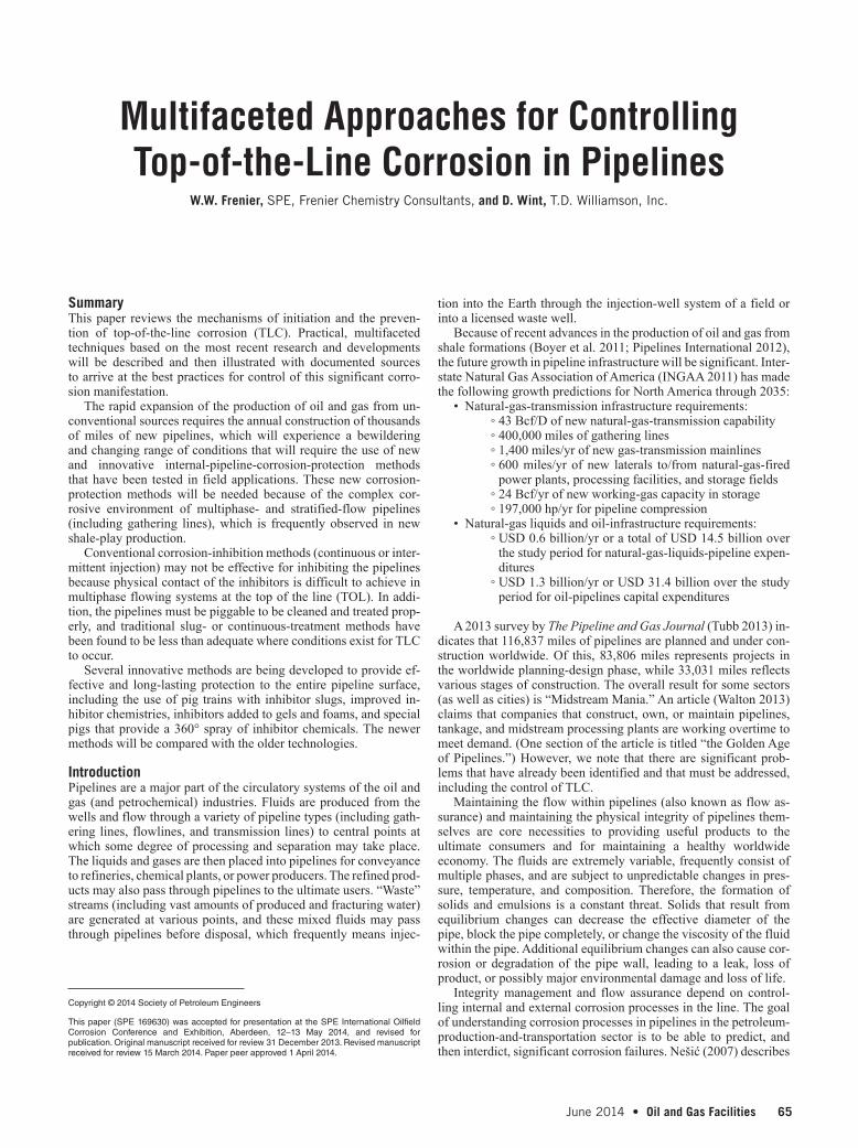
Testing of film persistence for TLC inhibitors is critical, and the reader is referred to the references in the preceding re-views. An electrochemical method by Oehler et al. (2012) is illustrated in Fig. 4. Details of inhibitor formulations that pro-vide extended times of film persistency are described in subse-quent sections.
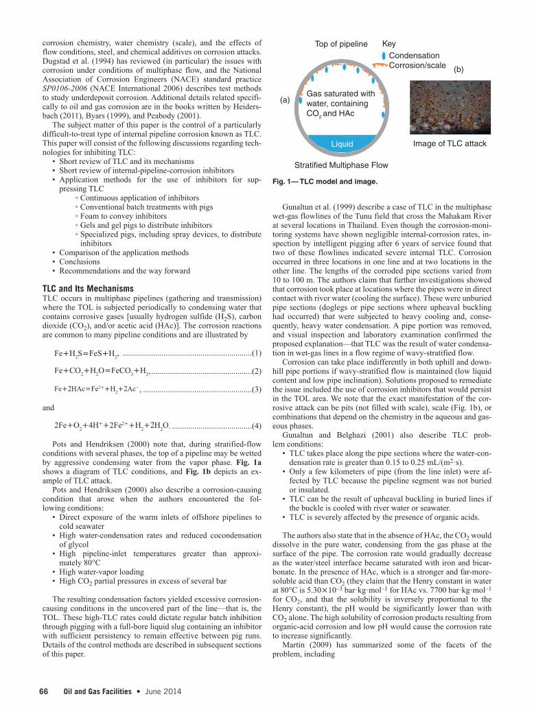
Application Methods for Corrosion Inhibitors in TLC ConditionsAs noted in the introductory sections, TLC occurs where there is multiphase flow in a pipeline. A simplified depiction is seen in Fig. 5. The image shows only four possible scenarios out of a very large range that are beyond the scope of this paper. See Kesana (2013), Thome (2010), and Asante (2002) for additional conditions and models.
Any of these flow regimes that exist with water-condensing con-ditions will make inhibition of the TOL physically difficult to ac-complish and will tend to degrade an adsorbed inhibitor film. In Conditions A, B, and D, the inhibitor film may not form initially. The following subsections will describe conventional and newer application methods for providing 360° coverage of pipe surfaces, along with the necessary persistency times between applications.
Continuous or Periodic Injection Into the Flow Stream. On-shore and at readily accessible locations, injection of inhibitors or other treatment chemicals may be as simple as locating a tank of the chemical at the wellhead or at a convenient place along the pipeline (such as at a pumping station), and then injecting the treat-ment chemical into the flow stream by use of an appropriately sized pump or with an educator pump to draw the chemicals from the tank. As long as there is sufficient turbulence to disperse the chem-icals, 360° coverage can be accomplished. However, many types of complications exist, especially because, between injection stations (frequently downstream of pumps), chemical and flow conditions may differ (see Fig. 5). Some of the many physical and chemical conditions that may have an effect on the coverage are described in subsequent paragraphs.
Chen et al. (2003) claim that they have developed a mechanistic chemical-dispersion model to aid in optimizing corrosion-inhib-itor injection. The mechanism of corrosion inhibition is attributed to the adsorption of inhibitor to the pipe wall to create a hydro-phobic layer. It is claimed to account for the mechanisms gov-erning the distribution of corrosion inhibitor, including the gross distribution of oil/water/gas in the pipeline, turbulent dispersion in the free-water phase, partitioning of the inhibitor between oil and water phases, and the adsorption/desorption of inhibitor on the pipe wall. This model can also calculate the inhibitor concentration in the liquid phases and on the wall in the flowline. The basis of the model (as described by the authors) is that solute (corrosion-in-hibitor) distribution entails an accurate calculation of velocity and phase distribution in a pipe. However, because of the complexity of the physical process, they note that they are currently able to com-pute cross-section averaged values of phase fraction and velocity only. The 3D-flow phenomenon is modeled by a 1D approxima-tion. This approach has allowed the authors to solve the distribution of solute in terms of the cross-section averaged variables. Thus, the authors contend that this mechanistic model should be a useful tool in the design of optimal corrosion-inhibitor injection for corrosion control (i.e., determining the minimum inhibitor concentration re-quired to provide the maximum inhibition protection).
Wang et al. (2002) claim that pipeline conditions that result in slug flow [see Thome (2010)], in which bubbles may form in the line, may result in an incomplete formation of an inhibitor film, even when there is enough turbulence to transport the inhibitors to
the TOL. The authors of this paper cite Kaul (1996), who showed that inhibitors behave differently in full-pipe and slug flows. The claim is that the inhibitors are more effective in full-pipe flow than in slug flow, with the effectiveness in full-pipe flow being close to 100%, while less than 50% in many cases of slug flow.
Additional complications can arise during treatment-fluid injec-tion because of unwanted chemical interactions. Rondon Gonzalez et al. (2012) has described the use of both corrosion and scale in-hibitors in a production train. They note that the injection of mul-tiple chemicals, such as antiscale and anticorrosion additives, must often take place sequentially or simultaneously at very close injec-tion points. Thus, it is necessary not only to evaluate the efficiency of chemicals individually, but also to screen for incompatibilities and/or interference between chemicals. These interferences can have an effect on the antiscale efficiency, the anticorrosion effi-ciency, or both additive efficiencies at the same time. This kind of
Fig. 4—Cold-finger LPR probe for TLC tests (Oehler et al. 2012).
Fig. 5—Multiphase flows and terrain in gas pipelines.
Thermometer
Bulk Solution
Hot Plate
Sampling Port
Condensed Water
TOC LPR Probe
CoolantCO2
Condition A
Condition B
Condition C
Condition D
Flow Rate
Stratified flow(Low gas velocity)
Multiphase Flow and Uneven Terrain in Pipelines
Liquid Movement in Gas Pipelines
Annular-mist flow(Intermediate gas velocity)
Mist flow(High gas velocity)
Terrain

68 Oil and Gas Facilities • June 2014 June 2014 • Oil and Gas Facilities 69
mutual reduction of efficiency may have been the reason for past pipeline failures, where both scaling and corrosion were observed despite the addition of large quantities of both additives. As a result of experiments conducted by these authors, it was found that there exists only a small range at which concentrations of scale inhibitor and a corrosion inhibitor are both effective. See Rondon Gonzalez et al. (2012; their Fig. 3) and Poggesi et al. (2002) for examples.
Continuously placed inhibitors usually go into the aqueous phase, and, thus, require both solvent and surfactants to aid in dis-persion into the phase. Miksic et al. (2013) propose an inhibitor formulation for use in continuous-injection pipeline operations. It describes a solvent used as a “carrier,” and examples in their patent of active ingredients (AIs) include a fatty acid anhydride and a 21-carbon dibasic acid with an amine or imidazoline to form a corrosion inhibitor consisting essentially of a fatty-acid deriva-tive. They then dissolve the inhibitor in a fatty-acid oil or ester selected from the group consisting of soybean oil or methyl soya ester. To make this inhibitor water dispersible, they add sulfonates and a long-chain ethoxylated alcohol and adjust the viscosity with an alcohol comprising isopropanol. The authors of this book claim that this patent provides a good example for producing a useful cor-rosion-inhibitor formulation.
Freeman and Williamson (2006) describe a process that includes the use of an injection nozzle inserted into a line at or near the well-head or just downstream of a compressor/pumping station, which injects corrosion inhibitor into the line under high pressure, va-porizing it where it mixes with the gas and/or liquids in the line. Corrosion inhibitors used in these applications are typically water soluble. The chemical enters the solution and travels with liquid water on the bottom of the pipeline. Direct contact between the pipe wall and water is the primary mechanism for inhibitor transfer.
Gravity effects, low flow rates, and stratified flow make transfer of the corrosion inhibitor to the TOL improbable at many locations. As water vapor and other gases travel along the pipeline, they are cooled. The cooling allows water vapor to condense on the upper portions of the internal pipe wall. The condensed water often con-tains no corrosion inhibitor (or contains insignificant quantities thereof) and does not provide any corrosion protection. In the pres-ence of certain acid gases, corrosion rates can be very high in the upper portions of the line.
The other extreme may be the injection of chemicals into a subsea-well system. Ludlow et al. (2010) describe a high-pressure pump for use in the injection of liquid chemicals into subsea oil or gas wells, which was intended to be positioned in the subsea envi-ronment adjacent to the wellhead. The system comprises a piezo-electric actuator for reciprocating a plunger, which acts to compress
and expand the effective volume of a pumping chamber. A valved inlet is connected to the source of the liquid and a valved outlet leads the liquid to the well. The device is described as having a minimum of moving parts, and, in particular, avoids the need for any rotating parts or high-performance bearings and seals.
In many cases, a corrosion probe (or other sensor) can be set to start inhibitor introduction automatically when a set point is reached and to cease introduction when the desired effect is achieved. Electronic corrosion probes are at the heart of automated monitoring and corrosion-control systems. Szabo et al. (2009) as-serts that many of the costs related directly to corrosion may be mitigated and managed with continuously monitored corrosion transmitters as part of a comprehensive plantwide control strategy. Process-parameter effects related to electrochemical corrosion may be minimized by means of direct, continuous corrosion feedback for active control and optimization of neutralizing agents (e.g., in-hibitors). A system described in this report has an LPR probe with readings of general corrosion, localized corrosion, and fluid con-ductance (Fig. 6a). The signals are sent to a data analyzer, which interprets the input signals and sends the data to an alarm/control unit. An example of a corrosion-rate output signal can be found in Fig. 6b. The signals can alert the operator to activate corrosion-inhibitor flows, or the system can be programmed to start the in-jection systems automatically. Fig. 6 depicts extended probes, but flat-surface-mounted probes are also available (Alabama Specialty Products 2012). For TLC control, the flow conditions must be ap-propriate to distribute a nonvolatile inhibitor to the TOL.
Because complete distribution of chemicals to the TOL is dif-ficult to achieve or predict under varying pipeline conditions, in-jection of several different chemical additives to the flow stream is claimed to improve TLC inhibition, even under unfavorable flow conditions.
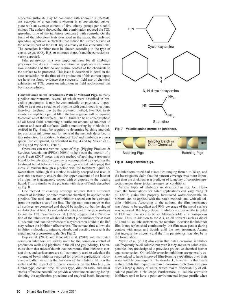
Because most inhibitor formulations are designed to stay in the liquid phase, the issue of volatility is being addressed by sev-eral authors. One method for protecting against TLC uses inhibi-tors that vaporize from the flowing aqueous phase at the bottom of the line (BOL). These vapor-phase inhibitors (VPIs) may also be part of a more conventional inhibitor formulation. The vapor-space pipelines may thus be protected by VPIs designed to be volatile under the flowing conditions. Martin (2009) refers to these types of chemicals, and specific citations by Oehler et al. (2012) describe the testing of primary, secondary, and tertiary volatile amines as specific TLC inhibitors. The exact chemicals are not described, but patents (Anbarasi et al. 2013) disclose the use of several volatile amines seen in Fig. 7.
Miksic et al. (2013) also describe the testing of volatile TLC in-hibitors with devices similar to those described in Fig. 4. Their re-sults show that some azoles and acetylene alcohols provided TOL protection, while some other tested acetylene alcohols showed pit-ting, as did some tested sulfur-containing compounds. Blended products were claimed to be more effective in an HAc-containing fluid than any single chemical. See Jenkins (2011) and Frenier (2003) for examples of organic acid/chelate solvent inhibitors with an AI blended with sulfur.
Narasaiah et al. (2013) describe work (chemistries not revealed) to develop inhibitor formulations that would protect both the BOL and the TOL with a single formulation that would be added con-tinuously (not batched) to the pipeline flow. We conclude that such a formulation may contain both nonvolatile and volatile filming molecules.
Schmitt et al. (2001) assert that “film spreading agents” can be added to the inhibitor formulation to promote the chemi-cals to spread and cover all surfaces. The central claim of the re-port is that careful tuning of the spreading system, composed of the 1- or 2-phase BOL liquids, spreading agents, and the corro-sion inhibitor, yields optimum corrosion protection on the entire pipeline surface, even at high-water-condensation rates. The au-thors claim that perfluorosurfactant tetraethylammonium perflu-
GGeneralLocalized
Conductance
(a)
(b)
High
Elevated
Normal
General-Corrosion Output Signal
Time
Trip Alarm or Control
Signal
LPR probe Analysis and Control Signals
LC
Fig. 6—Automated corrosion monitoring and alarm/control sys-tem (Szabo et al. 2009).
70 Oil and Gas Facilities • June 2014 June 2014 • Oil and Gas Facilities 71
orooctane sulfonate may be combined with nonionic surfactants. An example of a nonionic surfactant is tallow alcohol ethox-ylate with an average content of five ethoxy groups per alcohol moiety. The authors showed that this combination reduced the TOL spreading time of the inhibitors compared with controls. On the basis of the laboratory tests described in the paper, the preferred spreading agents are surfactants that reduce the surface tension of the aqueous part of the BOL liquid already at low concentrations. The corrosion inhibitor must be chosen according to the type of corrosive gas (CO2, H2S, or mixtures thereof) and the corrosion se-verity expected.
Film persistency is a very important issue for all inhibition processes that do not involve a continuous application of corro-sion inhibitor and that do not require contact of the chemicals to the surface to be protected. This issue is described in detail in the next subsection. At the time of the production of this current paper, we have not found evidence that successful field use of chemical enhancers of TOL corrosion inhibition in field applications has been accomplished.
Conventional Batch Treatments With or Without Pigs. In many pipeline environments, several of which were described in pre-ceding paragraphs, it may be economically or physically impos-sible to treat some stretches of pipeline with continuous injections; therefore, batching may be the preferred method. For TOL treat-ments, a complete or partial fill of the line segment will be required to contact all of the surfaces. The fill fluid can be an aqueous phase of oil-based fluid, containing a sufficient amount of inhibitor to contact and coat all surfaces. Online monitoring by methods de-scribed in Fig. 6 may be required to determine batching intervals for corrosion inhibitors and for some of the methods described in this subsection. In addition, testing of TLC and inhibition requires specialized equipment, as described in Fig. 4 and by Miksic et al. (2013) and Wylde et al. (2013).
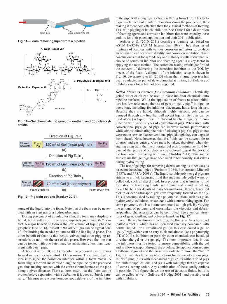
Operators can use various types of pigs [Pigging Products & Services Association (PPSA) 2008b] to help coat the interior of a pipe. Pruett (2005) notes that one method of applying a treatment liquid to the interior of a pipeline is accomplished by capturing the treatment liquid between two pipeline pigs (called batch pigs) that move in tandem through a pipeline with the treatment liquid be-tween them. Although this method is widely accepted and used, it does not necessarily ensure that the upper quadrant of the interior of a pipeline is adequately coated with or exposed to the treating liquid. This is similar to the pig train with slugs of fluids described in Fig. 8.
One method of ensuring coverage requires that a sufficient amount of inhibitor (or other treatment chemical) be applied to the pipeline. The total amount of inhibitor needed can be estimated from the surface area of the line. The pig train must move so that all surfaces are contacted and should be applied so that the slug of inhibitor has at least 15 seconds of contact with the pipe surfaces to coat the TOL. Van Gelder et al. (1988) suggest that a 5% solu-tion of the inhibitor in oil should contact pipe surfaces for at least 10 seconds and that the presence of a hydrocarbon liquid in the line may reduce the inhibitor effectiveness. The contact time allows the inhibitor molecules to migrate, adsorb, and possibly react with the metal and/or a corrosion scale. See Fig. 2.
Bojes et al. (2001) and Menendez et al. (2010) note that batch corrosion inhibitors are widely used for the corrosion control of production wells and pipelines in the oil and gas industry. The au-thors claim that rules of thumb that incorporate film thickness, con-tact time, and surface area are still commonly used to calculate the volume of batch inhibitor required for pipeline applications. How-ever, actually measuring the thickness of the inhibitor film on the metal and the impact of different variables on the film (e.g., in-hibitor type, contact time, diluents type, dilution ratio, and shear stress) offers the potential to provide a better understanding for op-timizing the application procedure and required batch frequency.
The inhibitors tested had viscosities ranging from 4 to 18 cp, and the investigators claim that the percent coverage was more impor-tant than the thickness as a predictor of longevity of corrosion pro-tection under shear- (rotating-cage) test conditions.
Various types of inhibitors are described in Fig. A-1. How-ever, the formulations for batch applications can vary. Yang et al. (2007) claim that properly formulated water-dispersible in-hibitors can be applied with the batch methods and with oil-sol-uble inhibitors. According to the authors, the film persistency was found to be excellent and 90% coverage of the metal surface was achieved. Batch/pig-placed inhibitors are frequently targeted at TLC and may need to be soluble/dispersible in a nonaqueous phase. Thus, in addition to the AIs, an oil solvent (such as diesel oil) and oil-soluble surfactants are required. Because the inhibitor film is not replenished continuously, the film must persist during contact with gases and liquids until the next treatment. Agents that increase the viscosity and the film persistence may also be in the formulation.
Wylde et al. (2013) also claim that batch corrosion inhibitors can frequently be oil soluble, but even if they are water soluble/dis-persible, they are designed to provide a protective chemical barrier against corrosion. Oil-soluble corrosion inhibitors are generally ac-knowledged to have improved film-forming capabilities over their water-soluble counterparts. The drawback, however, is that many mature fields that require increased corrosion protection also pro-duce a large quantity of water, which makes dispersability of oil-soluble products a challenge. Furthermore, oil-soluble corrosion inhibitors tend to have a poor environmental-impact profile when
Fig. 7—Volatile amine corrosion inhibitors.
Inhibitor Batch orOther Chemical
Batching Pigs Batching Pigs
Fig. 8—Slug between pigs.

70 Oil and Gas Facilities • June 2014 June 2014 • Oil and Gas Facilities 71
compared with water-soluble products. The authors claim that dilu-ents, such as field condensate/crude, diesel, or other aromatic sol-vents, can be used to dilute the inhibitor, which results in a larger batch volume, yielding improved contact time with the metal sur-face to be protected. These authors tested
• A blend of water-soluble alkoxylated amido amine, quat am-monium compound, and imidazoline with sulfur synergist
• An oil-soluble blend of imidazoline, fatty-acid alcohol, and dimer acids
• A water-dispersible blend of aliphatic amines, ethoxylated al-cohol derivatives, and a sulfur synergist
In their laboratory tests, the oil-soluble blend was the most ef-fective, while the water-dispersible product was determined to be preferable to the water-soluble blend. For any TLC inhibitor, the persistence of the material must be optimized to provide protection for as long as possible. Fig. A-1 describes the basic chemistries of inhibitors used to reduce the impact of both sweet and sour cor-rosion. The choice of AIs and other additives is predicated on the basis of the corrosion process, the fluid phase that requires inhibi-tion, and the target location and mechanism for replenishment of the inhibitor film.
De Marco et al. (2001) and Durnie et al. (2002) studied a list of pure corrosion inhibitors (see Table 1 and Fig. A-2) to understand the persistence at a surface molecular level. The authors used film-persistency tests, along with several surface-analytical methods, to study adsorption. The film-persistency measurements have been conducted extensively with various techniques [such as Fig. 4, Miksic et al. (2013), and Wylde et al. (2013)], and electrochemical impedance spectroscopy, polarization resistance, electrochemical noise analysis, and impinging jet electrodes. They claim that some work has been carried out to extend these studies to investigations of inhibitor films in the presence of both high fluid shear stresses and multiple phases.
De Marco et al. (2001) and Durnie et al. (2002) claimed to have developed a tentative quantitative structure/activity relationship for 16 corrosion inhibitors (Table 1), and the results demonstrated unambiguously that some compounds undergo chemisorption and display good persistence, while other inhibitors are not persistent and may experience physisorption. Durnie et al. (2002) seemed to agree with surface-analysis studies referenced in De Marco et al. (2001) (i.e., surface-enhanced Raman spectroscopy, surface reflec-tion Fourier-transfer infrared spectroscopy, and X-ray diffraction
spectroscopy) that inhibitors based on a succinic anhydride func-tionality are chemisorbed at the surface of mild steel through the formation of an Fe(II)/(III)-dicarboxylate complex. These authors also claim that even if the inhibitor is strongly adsorbed, it still has to adsorb (and remain) in the presence of an oil to provide good persistency.
The reactions with the surface are claimed to include the chemi-sorption of the dicarbocylic acid onto the surface:
Fe2+(ads)+R(COOH)2(ads) R(COO−)2Fe2+
(ads)+2H+(aq) ................(5)
These authors (De Marco et al. 2001; Durnie et al. 2002) note that on the basis of their experimental work, the most persistent inhibitors/formulations also adsorb a film of hydrocarbon that in-creases the hydrophobisity of the surface product, and thus, in-creases the time for removal and for the increase of the corrosion rate to the uninhibited values.
Cain and Rosenthal (1993) claim to have developed a poly-amine-based inhibitor that is a film-persistent, water-dispersible corrosion inhibitor. It is a quaternary ammonium salt that was op-timized for brine dispersability and corrosion inhibition. The au-thors note that the inhibitors were derivatives of methylated tertiary amines made from a process that uses methyl chloride, methyl sul-fide, benzyl chloride, and methyl phosphoric acid. The inhibitor was tested at several concentrations under many accepted industry methods, including kettle tests and continuous and film-persistence wheel tests. They claim that the inhibitor performance in those tests was equivalent or superior to the performance of common quater-nary intermediates at only one-quarter of their concentrations.
Most importantly, the authors claim that the inhibitor displays excellent film persistence. This can be a major advantage because most existing water-soluble corrosion inhibitors are purported to have very poor film persistence and must be administered continu-ously rather than in batches. Improving surface contact while pos-sibly avoiding the need for pigs has been the goal of applications with foams or gels.
Inhibitor Application With Foams or Gels. Treatments to reduce TLC with inhibitors added to foams or chemical gels represent an emerging technology area. These thickened fluids have the ability to fill an entire pipeline segment with a higher (than an unmodi-
TTAABBLLEE 11——CCOO22 IINNHHIIBBIITTOORRSS SSTTUUDDIIEEDD AANNDD PPRROOBBAABBLLEE AADDSSOORRPPTTIIOONN
MMEECCHHAANNIISSMMSS ( DE MARCO ET AL. 2001)
Inhibitor Compound Adsorption Mechanism
Hexadecenylsuccinic anhydride Chemisorption
Hexadecylsuccinic anhydride Chemisorption
Octenylsuccinic anhydride Chemisorption
Benzyldimethylhexadecylammonium chloride Physisorption and/or chemisorption
Trimethylhexadecylammonium chloride Physisorption and/or chemisorption
Lauric acid Physisorption and/or chemisorption
Sebacic acid Physisorption and/or chemisorption
Cetylpyridinium chloride Physisorption and/or chemisorption
Cetylamine Physisorption and/or chemisorption
Stearylamine Physisorption and/or chemisorption
Dimethyldodecylamine Physisorption and/or chemisorption
Nalco/Exxon product Physisorption and/or chemisorption
Cetylcyanide Physisorption and/or chemisorption
Cetylmercaptan Physisorption and/or chemisorption
Dimethyldipalmitylammonium chloride Possibly physisorption
Folic acid Chemisorption

72 Oil and Gas Facilities • June 2014 June 2014 • Oil and Gas Facilities 73
fied liquid) viscosity fluid that may increase the film persistency. These modified fluids have wide applications in industrial cleaning (Frenier 2001) and in many oilfield-production operations (Frenier and Ziauddin 2014). In either case, the inhibitor formulation must be compatible with the foam or gel, and then must adsorb onto the metal surfaces to protect them from corrosion between treatments.
Foams as Inhibitor Carriers. A foam phase can be formed in pipe-lines, and various treatment chemicals, such as corrosion inhibitors, can be added to the foaming fluid and used to coat all pipeline sur-faces. Foams that are used in pipelines or process-vessel cleaning treatments require a liquid source, a gas (usually a hydrocarbon gas, N2, or CO2), and a surfactant that is compatible with the liquid phase to stabilize the foam (Kelland 2009). A micrograph of gas bubbles (coated with liquid and a surfactant) settling in a vessel is shown in Fig. 9.
Foams are coarse dispersions of gas in a relatively small amount of liquid. See Rossen (1990) for more details regarding foam theory, as well as the discussions in Frenier and Ziauddin (2014). In oilfield nomenclature, the “quality” of foam is expressed as
Foam quality= •100Vg
Vg+Vl
, ................................................(6)
where Vg is the volume of the gas and Vl is the volume of the liquid. The sum is the volume of the foam. Foam quality is considered to range from 52 to 95%. At greater than 95%, the foam usually changes to a mist, with gas as the continuous phase. At less than approximately 52%, stable foam does not exist because there are no bubble/bubble interactions to provide resistance to flow or to gravity separation. At a foam quality greater than 52%, the gas con-centration is high enough that the bubble surfaces touch. Fluids with less than 90% quality are frequently called energized fluids in production operations, and foams are fluids in the 90 to 95% range. Note that this same equation (Eq. 6) can be used to calculate a foam quality with a liquid/gas flow rate as long as the volumes of fluids and the flow rates are known. It is clear from Eq. 6 and Karam (2012) that foam can occupy a much larger volume than an equivalent mass of liquid.
Foams cannot form from pure liquids. The thermodynamic equation is
∆F=s∆A−p∆V , ....................................................................(7)
where ΔF is the change in Helmholtz free energy at constant T, s is the surface tension of the liquid, A is the surface area of the liquid, p is the pressure, and V is the volume of the gas. Eq. 7 applied to a foam shows that a decrease in free energy results from the loss of area and expansion of the gas, both of which come about by co-alescence of the bubbles; hence, foam composed of a pure liquid is thermodynamically unstable.
The third component necessary for stable foam is usually a solute in the liquid, but can also be a finely divided solid, a liquid/crystal, or an insoluble monolayer. The stabilizer (foaming agent) must be surface active (migrate to the interface) and must be ad-sorbed positively. The work necessary to desorb the stabilizer is added to Eq. 7 to give
∆F=s∆A−p∆V+W(desorption) . ..........................................(8)
This term may make the entire equation positive (more ther-modynamically stable); however, even when the foam is not completely stable (as is the case with most foams), the work of de-sorption reduces the decay rate of the foam.
Foams can be generated in many ways, but the use of shear in a foaming device is one method. The simple setup seen in Fig. 10 shows a water/surfactant (or hydrocarbon/surfactant) mixing with
a second fluid, such as an acid or a concentrated corrosion inhib-itor, and then with the gas phase. Different surfactants are required for different aqueous-fluid foams and hydrocarbons. With enough shear, foam can be formed directly in the pipeline by injecting a gas into a liquid flow. Examples of the use of foam to clear liquid from lines and other treatments, including addition of corrosion inhibi-tors, are described in the subsequent paragraphs.
Several authors describe the use of foam to remove liquids from gas lines. (See the photo of foam forming in Fig. 9.) Karam (2012) lists several surfactants suitable for producing a pipeline foam to remove liquids for subsea gas lines. These include ammonium salts of alcohol, ether sulfates, and olefin sulfonates. These are an-ionic, cationic, and amphoteric surfactants [see the discussion of foaming agents in Kelland (2009)]. For use as an inhibitor carrier, a sufficient amount of inhibitor (enough to contact all of the sur-faces) must be added to the liquid phase and be compatible with the foaming agent. Karam (2012) claims that foam transport in the pipe can consist of a pipe completely filled with foam, which ensures a homogeneous plug-flow regime along the line; and a pipe par-tially filled with foam, which causes intermittent foam plugs, thus sweeping liquid from the pipeline more efficiently than gas alone. Uses for foam as described by Karam (2012) include the preven-tion of liquid accumulation in gas lines and the removal of liquid from gas lines.
Fig. 11 shows the removal of liquid from the pipeline by use of foam. The mechanism can include physical removal because the foam is more viscous than the liquid or can include incorporating
Fig. 9—Microscopic view of foam being formed.
Fig. 10—Foaming setup for gas, liquid, and chemical injection (Achour et al. 2010).
Check Valve
Check ValveCheck Valve Foam
Injector
MixerPump
Pump
Surfactant and water
Gas space
Liquid Flow
Inhibitor or other chemical
Control Valve Gas
Pipe
72 Oil and Gas Facilities • June 2014 June 2014 • Oil and Gas Facilities 73
some of the liquid into the foam. Note that the foam can be gener-ated with an inert gas or a hydrocarbon gas.
During placement of an inhibitor film, the foam may displace a liquid, but it will also fill the line completely and make 360° con-tact. A major benefit of foam is the low volume of liquid phase to gas phase (see Eq. 6), thus 80 to 90 vol% of gas can be a great ben-efit for limiting the needed volume to fill the line liquid phase. The other benefit of foam is that bends, valves, and other pigging re-strictions do not limit the use of this phase. However, the line that can be treated with one batch may be substantially less than treat-ment with batch pigs.
Achour et al. (2010, 2011) describe the proposed use of foams formed in pipelines to control TLC corrosion. They claim that the idea is to inject the corrosion inhibitor within a foam matrix. A foam slug is formed and carried along the pipeline by the produced gas, thus making contact with the entire circumference of the pipe along a given distance. These authors assert that the foam can be broken before separation with a defoamer if it does not break natu-rally. This process ensures homogeneous delivery of the inhibitor
to the pipe wall along pipe sections suffering from TLC. This tech-nique is claimed not to interrupt or slow down the production, thus making it more cost effective than the classical methods of treating TLC with pigging or batch inhibition. See Table 2 for a description of foaming agents and corrosion inhibitors that were tested by these authors for their patent application and their 2011 publication.
Achour et al. (2010, 2011) describe a foaming test based on ASTM D892-98 (ASTM International 1998). They then tested mixtures of foamers with various corrosion inhibitors to produce an optimal blend for foam stability and corrosion inhibition. Their conclusion is that foam tendency and stability results show that the choice of corrosion inhibitor and foaming agent is a key factor in applying the new method. The corrosion-testing results confirmed the concept of delivering the corrosion inhibitor to the TOL by means of the foam. A diagram of the injection setup is shown in Fig. 10. Jevermovic et al. (2013) claim that a large loop test has been conducted as part of developmental activities, but field use of inhibitors in a foam has not been reported.
Gelled Fluids as Carriers for Corrosion Inhibitors. Chemically gelled water or oil can be used to place inhibitor chemicals onto pipeline surfaces. While the application of foams to place inhibi-tors has few references, the use of gels or “gelly pigs” in pipeline operations, including for inhibitor placement, has a long history. Because they are liquid, although highly viscous, gels can be pumped through any line that will accept liquids. Gel pigs can be used alone (in liquid lines), in place of batching pigs, or in con-junction with various types of conventional pigs. When used with conventional pigs, gelled pigs can improve overall performance while almost eliminating the risk of sticking a pig. Gel pigs do not wear out in service like conventional pigs (though they can degrade from shear). Note, however, that the fluids can be susceptible to dilution and gas cutting. Care must be taken, therefore, when de-signing a pig train that incorporates gel pigs to minimize fluid by-pass of the pigs, and to place a conventional pig at the back of the train when displacing with gas (PetroMin 2013). This source also claims that gel pigs have been used to temporarily seal valves during hydro testing.
The use of gel pigs for removing debris, among its other uses, is based on the technologies of Purinton (1984), Purinton and Mitchell (1987), and PPSA (2008a). The liquid-soluble polymer gel pigs are similar to a thick fracturing fluid that may include gelled water or gelled oil, such as diesel fluid. In a process that is similar to the formation of fracturing fluids [see Frenier and Ziauddin (2014); their Chapter 4 for details of many formulations], these gels (called pickup or debris-transport gels) are frequently formed on the fly. This is accomplished by mixing a polymer solution (such as a guar, hydroxyethyl cellulose, or xanthan) with a crosslinking agent. For some polymers, this is a borate compound at high pH. By varying the amount of polymer and crosslinker, the viscosity and debris-suspending characteristics can be controlled. See chemical struc-tures of guar, xanthan, and polyacrylamide in Fig. 12.
As in the applications in fracturing, the fluids can be a linear gel (called a “gel”), which has an increased viscosity compared with normal liquids, or a crosslinked gel (in this case called a gel or “gelly” pig), which can be very thick and almost like a polymer pig (TDW 2011). Inhibitors or possibly other chemicals can be added to either the gel or the gel pig. The most important idea is that the inhibitors must be tested to ensure compatibility with the gel and to allow transport through the pipeline. Gel applications require a full-line segment and the pressure available to move the “train.” Fig. 13 illustrates three possible options for the use of various pigs. In this figure, (a) is with mechanical pigs, (b) is without solid pigs for inhibitor applications, and (c) is with solid pigs that are capable of some cleaning action. Any combination of these configurations is possible. This figure shows the use of aqueous fluids, but oils can be gelled as well (Gulbis and Hodge 2001) and possibly used with inhibitors.
Fig. 12—Gel chemicals: (a) guar, (b) xanthan, and (c) polyacryl-amide.
Fig. 13—Pig train options (Mackay 2013).
Direction of Pig Train
(a)
(b)
(c)
Direction of Pig Train
120 m3 of Gel (linear polymer)
120 m3 of Gel (linear polymer)
70 m3 of Gel (linear polymer)
Foam Brush Pig Foam Brush Pig
FilteredSeawater
FilteredSeawater
FilteredSeawater
Foam Pig
Gel Pig(crosslinked
polymer)
Gel Pig(crosslinked
polymer)
Gel Pig(crosslinked
polymer)
Direction of Pig Train
Fig. 11—Foam removing liquid from a pipeline.
Foam plug Liquid in dips in the line

74 Oil and Gas Facilities • June 2014 June 2014 • Oil and Gas Facilities 75
Specific applications of gels for placing inhibitor films are re-viewed. Kennard and McNulty (1992) explore the use of gels to deposit inhibitors and biocides (PetroMin 2013). Because the gels are very viscous, they will support and aid in the placement of treating chemicals over the entire surface of the line. Note that the gels can be made from aqueous brines or can be oil based to ensure compatibility with the treatment being performed. PetroMin (2013) claims that many inhibitors can be dispersed into gelled-oil for-mulations. A reason to use gels (and foams) may apply if the line is very difficult to pig with mechanical devices. Even in pig-gable lines, there are advantages.
Quarini and Shire (2007) have reviewed the use of various types of pigs, including gel pigs, and several attributes of these fluids will aid in inhibitor placement, including
• The gels are unlikely to become stuck.• Because the gels conform to pipeline irregularities, all sur-
faces are contacted.• The gels enhance the sealing capacity of any mechanical pig
in the train.
Uzu et al. (2000) have reviewed gel-pig technologies and note that gel pigs can be used for many purposes, including cleaning and placement of chemicals such as corrosion inhibitors, bio-cides, dehydrating fluids, and paraffin solvents or inhibitors. These authors claim that as much as 20 vol% of the pig can be an inhib-itor formulation, and the pig can then effectively coat long sec-tions of a line. This author also claims that commercial applications
of inhibitors in a gel were conducted in 1982 to a 279-mile seg-ment of a 36-in. subsea (North Sea) wet-gas line.
Keys (2000) describes the conversion of an oil pipeline in 1997 to a gas-transport line and the use of gel pigs with various mechan-ical devices to clean and inhibit the surfaces. The gel stages helped to remove more than 1,000,000 lbm of debris for a 151-mile line in addition to providing an initial coat of corrosion inhibitor. Research by Akhiyarov (2007) confirms that the turbulent flow in a gel is useful for distributing an entrained/dissolved inhibitor efficiently over the pipe surfaces. Additionally, this reference provides de-tails of gel physical properties for different types of chemical gels.
While foams and gels have some applications for possibly im-proved surface contact with the surfaces to be inhibited, they will have to be “broken” at the end of the run. In addition, long contact with the surfaces or by addition of breakers (Frenier and Ziauddin 2014) may be needed to allow disposal of the fluids.
Applications of Inhibitors With Specialty Pigs. If a line is pig-gable, a specialty pig can be used to overcome problems with con-tacting all surfaces of the line. Pruett (2005) and Freeman and Williamson (2006) describe an alternative method that is based on application of the Bernoulli (or Venturi) effect to a specially constructed spray-producing pig, which uses the energy of bypass flow to do the work needed to redeploy and redistribute residual in-hibitor chemicals throughout the pipe run. Reusing or effectively transferring corrosion chemicals in pooled accumulations along the bottom of the pipeline has been viewed as an alternative to “chem-
TTAABBLLEE 22——FFOOAAMMIINNGG AAGGEENNTTSS AANNDD CCOORRRROOSSIIOONN IINNHHIIBBIITTOORRSS
Foaming Agent Corrosion Inhibitor
N-decyl-N-dimethylamine oxide 3-methoxyproplamine
Dodecylaminodipropionate 3-Methoxyproplamine bromide
Sodium C14-16 olefin sulfonate Didicyldium ethyl ammonium bromide
Dodecylbenzene sulfonic acid Decylamine caprylate
Dentritic polymer (DP foamer) Corsicana® Dodecylbenzene Octylamine caprylate
Glucopon 215 UP Cyclohexylamine caprylate
Sealing cups and disks providethe tighest seal available.
The spray pig will act as its own reservoir by capturing the fluid between the fron and rear sealing elements. This provides the volume of fluid to supply the nozzles and ensure complete treatment of all pipe surfaces.
The use of the typical differential pressure associated with pigging allows the spray pig to siphon residual inhibitor lying in front of the pig through the nozzles and to redistribute it directly to the unprotected top inner wall of the pipe.
Counterweights ensure that the spray pig remains properly oriented in the pipeline.
Middle jets spray inhibitor fluid to saturate the top quadrant of the pipe.
Fig. 14—Pig train options (Mackay 2013).

74 Oil and Gas Facilities • June 2014 June 2014 • Oil and Gas Facilities 75
ical batching” and an effective step in solving the problem of TLC. Fig. 14 has a depiction of this device. The authors note that one method of using the spray pig can be applied when continuous in-jection is the primary means of introducing corrosion-inhibitor fluid into the pipeline. This method is effective on relatively level lines and pipelines with a continuous upgrade, such as those asso-ciated with offshore wells. The spray pig has proved to be a very effective dewatering pig, while it distributes inhibitor-containing fluids to the TOL. In this manner, a dense vapor cloud is created in front of the pig as it splashes through and jets the liquids.
Freeman (2009) reports on the use of a spray-pig system (similar to that in Fig. 14) for treating TLC that has been semiautomated to collect performance data. To eliminate this gap and provide more-immediate feedback on the performance of a spray pig in any given application, engineers have incorporated some existing inline-in-spection technologies into the body of the pig itself as an onboard data logger. It is, essentially, a spray pig with a “brain.” The author claims that the unit is capable of operating under normal spray-pig conditions, and the pig is equipped to collect a variety of informa-tion during every run. This includes data on differential pressure (ΔP), which is of key importance to achieving proper jetting ac-tion. The semismart spray pig gauges pressure at both the front and back of the pig. To be effective, a spray pig must deliver inhibitor to the top of the pipe. To verify that this is indeed happening, the semismart design also monitors rotation/orientation of the pig. The data acquired by the device offer a complete 3D profile of how the pig moved throughout the run, including tool rotation, spray-nozzle orientation, and port orientation. Should an improper orientation occur, the pig’s sensors can tell whether this was temporary or per-manent, and where it took place in the pipeline (for example, rela-tive to known corrosion areas).
Freeman and Williamson (2006) also note that the system is most effective if used in a “train” of a separator—a spray pig with
inhibitor and a foam pig to complete the application. Fig. 15 dem-onstrates a very important aspect of the successful application of an inhibitor to all metallic line surfaces. It shows the use of a scraper pig to help remove some of the surface scale and to allow the inhib-itor film to penetrate to the metal surface to provide long-term pro-tection. All inhibitor applications should be preceded by a cleaning step if possible.
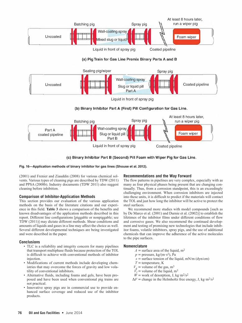
Shouse et al. (2012) claim that one method for performing a proper application of inhibitors to all parts of a pipeline is the use of a two-part corrosion inhibitor. This binary corrosion inhibitor is applied by modified batch with spray-pig technology, which en-sures full circumferential coverage of the internal pipe wall. The binary corrosion inhibitor is typically applied as a two-part system, in which Part A bonds molecularly with the metallic pipeline wall and Part B reacts and bonds with Part A, allowing it to be applied to pipelines with limited cleaning and surface-preparation require-ments. Proper application of the binary corrosion inhibitor delivers superior internal-corrosion protection for the pipeline operator/owner at a better economic cost/performance benefit over tradi-tional corrosion-inhibitor-treatment methods.
Tests in a 1,000-ft-loop test with corrosive water showed a re-duction in corrosion rates from 169 to 0.01 m/a after a 6-hour soak of the binary inhibitor. Field-performance and film-persistency tests (soak of treated pipe sections in pH 2 acid solution) have indi-cated that the active lifespan exceeds that of existing conventional pipeline-corrosion inhibitors. Tests conducted by these authors (Shouse et al. 2012) also show that this binary corrosion inhibitor has proved to reduce wax-deposition problems in crude-oil lines significantly, which results in lower maintenance and improved flow characteristics. See Fig. 16 for an illustration of the applica-tion method.
The importance of proper surface preparation cannot be over-emphasized for effective application and film life of an inhibitor. The inhibitor film will not adhere properly to a heavily scaled surface; therefore, application onto a pipeline surface requires thorough mechanical and possibly chemical cleaning before ap-plication, especially for batch treatments. While this is a com-plex situation, Kowata and Takahashi (1996) have demonstrated the effects of scale on corrosion inhibitors with laboratory tests of the interactions. The more-advanced methods of application (foam, gels, sprays) described previously will promote adhesion, but prior cleaning of the surface is still recommended. See Frenier
Fig. 15—Spray pig with train of additional devices (T.D. William-son, Inc.)
Separator/scraper pig
Liquid inhibitorSpray pig Foam pig
TTAABBLLEE 33——CCOOMMPPAARRIISSOONN OOFF PPIIPPEELLIINNEE TTLLCC CCOORRRROOSSIIOONN IINNHHIIBBIITTOORRSS
Method of Application Benefits Disadvantages Commercial
Status References
Injection of contemporary inhibitors
Uses current equipment and systems, used on line
Depends on line turbulence for distribution and TOL contact
Commercial Chen et al. 2003
Injection of advanced inhibitors
Uses current equipment and systems, on line and pigs not
needed
Complete surface coverage and film life not proved
Research phase
Schmitt et al. 2001
Batch treatments with slugs and pigs
Many years of experience and histories
Depends on line turbulence for distribution and TOL contact, may require excess inhibitor. Line must
be piggable and is off line
Commercial Bojes et al. 2001
Foams Uses less liquid, fills all parts of line, may be used on line
Depends on line turbulence for distribution and TOL contact, film
life not proved
Development phase
Achour et al. 2010
Gels Excellent surface contact, can be used with pigs for cleaning
Off line; with pigs, has downside of any pig treatment
Commercial Uzu et al. 2000
Spray pigs Excellent surface coverage, uses less inhibitor for coverage
Off line, line must be piggable Commercial Freeman and Williamson
2006
Spray pig with 2-step Inhibitor
Excellent surface coverage, long film life
Off line, line must be piggable Development phase
Shouse et al. 2012
76 Oil and Gas Facilities • June 2014 June 2014 • Oil and Gas Facilities 77
(2001) and Frenier and Ziauddin (2008) for various chemical sol-vents. Various types of cleaning pigs are described by TDW (2011) and PPSA (2008b). Industry documents (TDW 2011) also suggest cleaning before inhibition.
Comparison of Inhibitor-Application MethodsThis section provides our evaluation of the various application methods on the basis of the literature citations and our experi-ence in this field. Table 3 shows a comparison of the benefits and known disadvantages of the application methods described in this report. Different line configurations [piggable or nonpiggable; see TDW (2011)] may dictate different methods. Shear conditions and amounts of liquids and gases in a line may affect the choice as well. Several different developmental techniques are being investigated and were described in the paper.
Conclusions• TLC is a reliability and integrity concern for many pipelines
that transport multiphase fluids because protection of the TOL is difficult to achieve with conventional methods of inhibitor injection.
• Modifications of current methods include developing chem-istries that may overcome the forces of gravity and low vola-tility of conventional inhibitors.
• Alternative fluids, including foams and gels, have been pro-posed and have been used when conventional pig trains are not practical.
• Innovative spray pigs are in commercial use to provide en-hanced surface coverage and reduced use of the inhibitor products.
Recommendations and the Way ForwardThe flow patterns in pipelines are very complex, especially with as many as four physical phases being present that are changing con-tinually. Thus, from a corrosion standpoint, this is an exceedingly challenging environment. When corrosion inhibitors are injected into these units, it is difficult to predict if the materials will contact the TOL and just how long the inhibitor will be active to protect the steel surfaces.
We recommend more studies with model compounds [such as by De Marco et al. (2001) and Durnie et al. (2002)] to establish the lifetimes of the inhibitor films under different conditions of flow and corrosive gases. We also recommend the continued develop-ment and testing of promising new technologies that include inhib-itor foams, volatile inhibitors, spray pigs, and the use of additional chemicals that can improve the adherence of the active molecules to the pipe surfaces.
Nomenclature A = surface area of the liquid, m2
p = pressure, kg/(m·s2), Pa s = surface tension of the liquid, mN/m (dyn/cm) T = temperature, K Vg = volume of the gas, m3
Vl = volume of the liquid, m3
W = work of desorption, J, kg·m2/s2
ΔF = change in the Helmholtz free energy, J, kg·m2/s2
Fig. 16—Application methods of binary inhibitor for gas lines (Shouse et al. 2012).
76 Oil and Gas Facilities • June 2014 June 2014 • Oil and Gas Facilities 77
ReferencesAchour, M.H., Blumer, D.J., and Baugh, T.D. 2010. Controlling top
of the line corrosion in hydrocarbon pipelines US Patent Ap-plication No. US 20100304018 A1.
Achour, M., Blumer, D., Baugh, T. et al. 2011. A Novel Method to Mitigate Top of the Line Corrosion in Wet Gas Pipelines: Part I - Proof of Concept. Presented at the NACE Interna-tional CORROSION 2011 Annual Conference and Exposi-tion, Houston, 13–17 March. NACE-11332.
Akhiyarov, D. 2007. Gel Preparation and Properties Control for Operations in Pipeline Transport. Presented at the SPE An-nual Technical Conference and Exhibition, Anaheim, Cali-fornia, USA, 11–14 November. SPE-113785-STU. http://dx.doi.org/10.2118/113785-STU.
Alabama Specialty Products. 2012. Metal Samples Corrosion Mon-itoring Systems, http://www.alspi.com/ms.htm.
Anbarasi, M., Rajendran, S., Pandiarajan, M. et al. 2013. An En-counter with Corrosion Inhibitors. European Chemical Bul-letin 2 (4): 197–207.
Asante, B. 2002. Two Phase Flow: Accounting for the Presence of Liquids in Gas Pipeline Simulation. Presented at the PSIG An-nual Meeting, Portland, Oregon, 23–25 October.
ASTM D892-98, Standard Test Method for Foaming Character-istics of Lubricating Oils (Historical Standard). 1998. West Conshohocken, Pennsylvania: ASTM International. http://dx.doi.org/10.1520/D0892-98.
Bojes, J.M., Maddison, M., Girgis, M. et al. 2001. Batch Inhib-itor Film Distribution Studies: Correlation of Field Data with Laboratory Results. Presented at the NACE International CORROSION 2001 56th Annual Conference and Exposition, Houston, 11–16 March. NACE-01028.
Boyer, C., Clark, B., Jochen, V. et al. 2011. Shale Gas: A Global Re-source. Oilfield Review 23 (3): 28–39.
Byars, H.G. 1999. Corrosion Control in Petroleum Production, second edition. Houston, Texas: NACE Press.
Cain, J.J. and Rosenthal, L.M. 1993. Development of a Film-Persis-tent Water-Dispersible Corrosion Inhibitor. Presented at the SPE Annual Technical Conference and Exhibition, Houston, 3–6 October. SPE-26550-MS. http://dx.doi.org/10.2118/26550-MS.
Chen, H.J., Kouba, G.E., and Lee, S. 2003. Optimizing Corrosion Inhibitor Injection Rate in Flow Lines. Presented at the NACE International CORROSION 2003 58th Annual Conference and Exposition, San Diego, California, USA, 16–20 March. NACE-03626.
Chokshi, K., Sun, W., and Nesic, S. 2005. Iron Carbonate Scale Growth and the Effect of Inhibition in Co2 Corrosion of Mild Steel. Presented at the NACE International CORROSION 2005 60th Annual Conference and Exposition, Houston, 3–7 April. NACE-05285.
Craddock, H.A., Caird, S., Wilkinson, H. et al. 2006. A New Class of “Green” Corrosion Inhibitors: Development and Applica-tions. Presented at the SPE International Oilfield Scale Sym-posium, Aberdeen, 31 May–1 June. SPE-104241-MS. http://dx.doi.org/10.2118/104241-MS.
De Marco, R., Durnie, W., Jefferson, A. et al. 2001. Surface Anal-ysis of Adsorbed Carbon Dioxide Corrosion Inhibitors. Cor-rosion 57 (1): 9–18. NACE-01010009.
Dugstad, A., Lunde, L., and Nesic, S. 1994. Control of Internal Corrosion in Multi-Phase Oil and Gas Pipelines. Presented at the Prevention of Pipeline Corrosion Conference, Houston, 17–20 October.
Durnie, W., Jefferson, A., Kinsella, B. et al. 2002. Persistence of Carbon Dioxide Corrosion Inhibitors. Corrosion 58 (4): 354–363. NACE-02040354.
European Federation of Corrosion (EFC). 1994. Corrosion Inhibi-tors, No. 11. London: European Federation of Corrosion Se-ries, Maney Publishing/IOM3.
Fink, J.K. 2003. Oil Field Chemicals. Burlington, Massachusetts: Gulf Professional Publishing/Elsevier Science.
Fink, J.K. 2011. Petroleum Engineer’s Guide to Oil Field Chemi-cals and Fluids. Waltham, Massachusetts: Gulf Professional Publishing.
Freeman, E. 2009. Improving Corrosion Inhibition. Pipeline and Gas Technology (April 2009), http://www.midstreambusiness.com/Magazine/2009/4/.
Freeman, E.N. and Williamson, G.C. 2006. Top of Line Corrosion Rate Reduction Using V-Jettm Inhibitor Dispersal Pig. The Corrosionist, 30 November 2007, http://corrosionist.blogspot.com/2007/11/top-of-line-corrosion-rate-reduction.html.
Frenier, W.W. 2001. Technology for Chemical Cleaning of Indus-trial Equipment. Houston, Texas: NACE Press.
Frenier, W.W. 2003. Low hazard corrosion inhibitors and cleaning solutions using quaternary ammonium salts. US Patent No. 6,521,028.
Frenier, W.W. and Ziauddin, M. 2008. Formation, Removal, and Inhibition of Inorganic Scale in the Oilfield Environment. Richardson, Texas: SPE.
Frenier, W.W. and Ziauddin, M. 2014. Chemistry for Enhancing the Production of Oil and Gas. Richardson, Texas: SPE.
Gulbis, J. and Hodge, R.M. 2001. Fracturing fluid chemistry and proppants. In Formation Stimulation, third edition, ed. M.J. Economides and K.G. Nolte. Chichester, West Sussex, UK: John Wiley & Sons.
Gunaltun, Y.M., Supriyatman, D., and Achmad, J. 1999. Top of Line Corrosion in Multiphase Gas Lines. Presented at the NACE International CORROSION 99 54th Annual Confer-ence and Exposition, San Antonio, Texas, USA, 25–30 April. NACE 99036.
Gunaltun, Y.M. and Belghazi, A. 2001. Control of Top of Line Cor-rosion by Chemical Treatment. Presented at the NACE In-ternational CORROSION 2001 56th Annual Conference and Exposition, Houston, 11–16 March. NACE-01033.
Heidersbach, R. 2011. Metallurgy and Corrosion Control in Oil and Gas Production. Hoboken, New Jersey: John Wiley & Sons.
Henry, H., Meyer, R., Hicks, K. et al. 2005. The Design and Synthesis of Improved Corrosion Inhibitors. Presented at the NACE International CORROSION 2005 60th An-nual Conference and Exposition, Houston, 3–7 April. NACE-05282.
Interstate Natural Gas Association of America (INGAA). 2011. North American Midstream Infrastructure Through 2035 - A Secure Energy Future Report. Projections Report, The INGAA Foundation, Inc., Washington, DC (27 June 2011).
Jenkins, A. 2011. Performance of High-Temperature, Biodegrad-able Corrosion Inhibitors. Presented at the NACE Interna-tional CORROSION 2011 Annual Conference and Exposition, Houston, 13–17 March. NACE-11272.
Jevermovic, I., Miskovic-Stankovic, V., Achour, M. et al. 2013. Evaluation of a Novel Top-of-the-Line Corrosion (TLC) Miti-gation Method in a Large Scale Flow Loop. Presented at the NACE International CORROSION 2013 Annual Confer-ence and Exposition, Orlando, Florida, USA, 17–21 March. NACE-2013-2321.
Karam, T. 2012. Foam...The New Liquid Accumulation Reducer in Gas Pipelines. PowerPoint presentation, Norwegian Univer-sity of Science and Technology (NTNU), Trondheim, Norway (December 2012).
Kaul, A. 1996. Study of Slug Flow Characteristics and Perfor-mance of Corrosion Inhibitors in Multiphase Flow, in Hor-izontal Oil and Gas Pipelines. MS thesis, Ohio University, Athens, Ohio.
Kelland, M.A. 2009. Production Chemicals for the Oil and Gas In-dustry. Boca Raton, Florida: CRC Press.
78 Oil and Gas Facilities • June 2014 June 2014 • Oil and Gas Facilities 79
Kennard, M.A. and McNulty, J.G. 1992. Conventional Pipeline Pigging Technology: Pt. 2: Corrosion-Inhibitor Deposition Using Pigs. Pipes Pipelines Int. 37 (4): 14–20.
Kesana, N.R. 2013. Erosion in Multiphase Slug Flow. Presented to the Tulsa Section of NACE International, Tulsa, 22 April.
Keys, M. 2000. Conversion of Existing Crude Oil Pipelines Using Gel Pig Technology. Pipeline & Gas Journal 227 (3): 30–39.
Kowata, K. and Takahashi, K. 1996. Interaction of Corrosion In-hibitors with Corroded Steel Surface. Presented at the NACE International CORROSION 96 51st Annual Conference and Exposition, Denver, 24–29 March. NACE-96219.
Ludlow, J.L.C., Gore, J.G., Bowles, A.R. et al. 2010. Subsea Chem-ical Injection System and Pumps Therefor. US Application No. US20100074776 A1.
Mackay, N. 2013. Available Methodologies Concerning the Treat-ment and Removal of Sand From Pipelines and Associated Case Studies. Oil and Gas Facilities 2 (2): 61–71. SPE-163052-PA. http://dx.doi.org/10.2118/163052-PA.
Martin, R.L. 2009. Control of Top-of-Line Corrosion in a Sour Gas Gathering Pipeline with Corrosion Inhibitors. Presented at the NACE International CORROSION 2009 Annual Confer-ence and Exposition, Atlanta, Georgia, USA, 22–26 March. NACE-09288.
Menendez, C.M., Bojes, J.M., and Lerbscher, J. 2010. Obtaining Batch Corrosion Inhibitor Film Thickness Measurements Using an Optical Profiler. Presented at the NACE Interna-tional CORROSION 2010 Annual Conference and Exposi-tion, San Antonio, Texas, USA, 14–18 March. NACE-10272.
Miksic, B.A., Shen, M., Furman, A. et al. 2013. Vapor Corrosion Inhibitors for Top-of-the-Line Corrosion. Mater. Performance 52 (8): 56–59.
Moore, J. and Liu, J.-F. 2009. Corrosion Inhibitors in the Presence of Elemental Sulfur Paper. Presented at the NACE Interna-tional CORROSION 2009 Annual Conference and Exposi-tion, Atlanta, Georgia, USA, 22–26 March. NACE-09363.
Naraghi, A. and Grahmann, N. 1997. Corrosion inhibitor blends with phosphate esters. US Patent No. 5,611,992.
Narasaiah, V.K., Gangar, M.L., Garg, G. et al. 2013. Development of Continuous Application Based Corrosion Inhibitors to Mit-igate the Problems Caused by Top of the Line Corrosion in Upstream Oil and Gas Industry. Presented at the NACE In-ternational CORROSION 2013 Annual Conference and Exposition, Orlando, Florida, USA, 17–21 March. NACE-2013-2596.
Nešić, S. 2007. Key issues related to modelling of internal corro-sion of oil and gas pipelines – A review. Corros. Sci. 49 (12): 4308–4338. http://dx.doi.org/10.1016/j.corsci.2007.06.006.
Oehler, M.C., Bailey, S.I., Gubner, R. et al. 2012. Testing of Ge-neric Volatile Inhibitor Compounds in Different Top-of-the-Line Corrosion Laboratory Test Methods. Presented at the NACE International CORROSION 2012 Annual Conference and Exposition, Salt Lake City, Utah, USA, 11-15 March. NACE-2012-1483.
Palmer, J.W., Hedges, W., and Dawson, J.L. ed. 1994. Use of Cor-rosion Inhibitors in Oil and Gas Production, No. 39. London: European Federation of Corrosion Series, Maney Publishing.
Peabody, A.W. ed. 2001. Peabody’s Control of Pipeline Corrosion, second edition. Houston, Texas: NACE International.
PetroMin. 2013. A Pig for Every Reason. PetroMin Pipeliner 9 (2): 38–44.
Pigging Products & Services Association (PPSA). 2008a. Gel Pigs, http://ppsa-online.com/about-pigs.php#GEL PIGS.
Pigging Products & Services Association (PPSA). 2008b. About Pigs, http://ppsa-online.com/about-pigs.php.
Pipelines International. 2012. New crude oil pipeline proposed for Bakken Shale. Pipelines International (June 2012), http://
pipelinesinternational.com/news/new_crude_oil_pipeline_proposed_for_bakken_shale/069333/.
Poggesi, G., Hurtevent, C., and Buchart, D. 2002. Multifunc-tional Chemicals for West African Deep Offshore Fields. Presented at the International Symposium on Oilfield Scale, Aberdeen, 30–31 January. SPE-74649-MS. http://dx.doi.org/10.2118/74649-MS.
Pots, B.F.M. and Hendriksen, E.L.J.A. 2000. CO2 Corrosion under Scaling Conditions - the Special Case of Top of Line Cor-rosion in Wet Gas Pipelines. Presented at the NACE Inter-national CORROSION 2000 55th Annual Conference and Exposition, Orlando, Florida, USA, 26–31 March. NACE-0031.
Pruett, R.D. 2005. Inhibitor Dispensing Pipeline Pig. US Patent No. 6,874,193.
Purinton, R.J. Jr. 1984. Cleaning Pipeline Interior with Gelled Pig. US Patent No. 4,473,408.
Purinton Jr., R.J. and Mitchell, S. 1987. Practical Applications for Gelled Fluid Pigging. Pipe Line Ind. 66 (3): 55–56.
Quarini, J. and Shire, S. 2007. A Review of Fluid-Driven Pipe-line Pigs and their Applications. Proceedings of the In-stitution of Mechanical Engineers, Part E: Journal of Process Mechanical Engineering 221 (1): 1–10. http://dx.doi.org/10.1243/0954408jpme108.
Ramachandran, S. Ward, M.B., and Bartrip, K.A. 2002. Molec-ular Modeling of Corrosion of Iron in H2S Environments. Presented at the NACE International CORROSION 2002 57th Annual Conference and Exposition, Denver, 7–11 April. NACE-02240.
Rondon Gonzalez, M., Passade-Boupat, N., Bascoul, P. et al. 2012. Selection of Anti-scale and Anti-corrosion Products: How to Avoid Interactions? Presented at the SPE International Conference on Oilfield Scale, Aberdeen, 30-31 May. SPE-155235-MS. http://dx.doi.org/10.2118/155235-MS.
Rossen, W.R. 1990. Theory of mobilization pressure gra-dient of flowing foams in porous media: I. Incompressible foam. J. Colloid Interface Sci. 136 (1): 1–16. http://dx.doi.org/10.1016/0021-9797(90)90074-X.
Schmitt, G., Scheepers, M., and Siegmund, G. 2001. Inhibition of the Top-of-the-Line Corrosion Under Stratified Flow. Pre-sented at the NACE International CORROSION 2001 56th Annual Conference and Exposition, Houston, 11–16 March. NACE-01032.
Shouse, L., Logan, M., Brock, G. et al. 2012. Corrosion Preven-tion Technology Break-Through. Presented at the NACE International CORROSION 2012 Annual Conference and Ex-position, Salt Lake City, Utah, USA, 11–15 March. NACE-2012-1611.
SP0106-2006, Control of Internal Corrosion in Steel Pipelines and Piping Systems. 2006. Houston, Texas: NACE International.
Szabo, L.F., McElroy, M.I., Miller, L.J. et al. 2009. Controlling Corrosion in a Real-Time Environment: Fundamentals of Automatic Control in “Real-Time”. Presented at the NACE International CORROSION 2009 Annual Conference and Ex-position, Atlanta, Georgia, USA, 22–26 March. NACE-09460.
TDW. 2011. Guide to Pigging (brochure). Tulsa, Oklahoma: T.D. Williamson, Inc.
Thome, J.R. 2010. Two-Phase Flow Patterns. In Engineering Data Book III, Chap. 12. Shawnee, Oklahoma: Wolverine Tube, Inc.
Tsui, K., Wong, J.E., and Park, N. 2010. Effect of Corrosion In-hibitor Active Components on Corrosion Inhibition in a Sweet Environment. Presented at the NACE International CORRO-SION 2010 Annual Conference and Exposition, San Antonio, Texas, USA, 14–18 March. NACE-10326.
Tubb, R. 2013. Pipeline & Gas Journal’s 2013 Worldwide Con-struction Report. Pipeline & Gas Journal 240 (1).
Uzu, O., Napier, R., and Ngwuobia, K. 2000. Gel Pig Tech-nology Applications in Pipeline Servicing. Presented at the

78 Oil and Gas Facilities • June 2014 June 2014 • Oil and Gas Facilities 79
Nigerian Annual International Conference and Exhibition, Abuja, Nigeria, 7–9 August. SPE-66068-MS. http://dx.doi.org/10.2118/66068-MS.
Van Gelder, K., Van Bodegom, L., and Visser, A. 1988. Inhibition of CO2 Corrosion of Carbon Steel Pipelines Transporting Wet Gas. Materials Performance 27 (4): 17–21.
Walton, R. 2013. Midstream Mania - Oil Boom: Shale Success Makes Tulsa a Transport Hub. Tulsa World, 1 December 2013, http://www.tulsaworld.com/midstream-mania/article_bd8a00f4-7cce-5a8e-98b1-4b62e182decf.html?mode=story.
Wang, H., Wang, H., Shi, H. et al. 2002. Why Corrosion Inhibi-tors Do Not Perform Well in Some Wells in Some Multi-Phase Conditions: A Mechanistic Study. Presented at the NACE In-ternational CORROSION 2002 57th Annual Conference and Exposition, Denver, 7–11 April. NACE-02276.
Wong, J.E. and Park, N. 2008. Effect of Corrosion Inhibitor Active Components on the Growth of Iron Carbonate Scale Under CO2 Conditions. Presented at the NACE International COR-ROSION 2008 Annual Conference and Exposition, New Or-leans, 16–20 March. NACE-08345.
Wong, J.E. and Park, N. 2009. Further Investigation on the Effect of Corrosion Inhibitor Actives on the Formation of Iron Car-bonate on Carbon Steel. Presented at the NACE International CORROSION 2009 Annual Conference and Exposition, At-lanta, Georgia, USA, 22–26 March. NACE-09569.
Wylde, J.J., Reid, M., Kirkpatrick, A. et al. 2013. When To Batch and When Not To Batch: An Overview of Integrity Man-agement and Batch Corrosion Inhibitor Testing Methods and Application Strategies. Presented at the SPE Interna-tional Symposium on Oilfield Chemistry, The Woodlands, Texas, USA, 8–10 April. SPE-164080-MS. http://dx.doi.org/10.2118/164080-MS.
Yang, J., Jovancicevic, V., Mancuso, S. et al. 2007. High Perfor-mance Batch Treating Corrosion Inhibitor. Presented at the NACE International CORROSION 2007 Annual Conference and Exposition, Nashville, Tennessee, USA, 11–15 March. NACE-07693.
Appendix A—Chemical StructuresSee Figs. A-1 and A-2.
O
Hexadecylsuceinic anhydride
Hexadecyltrimethylammonium bromide
Imidazoline Amine [R X (CmH2mOn)]k PO(OH)(3-k)
Phosphate Ester StructureR=phenol or diphenolX=a carboxyl group, oxygen or an amine
Oleylimidazolines
H2N NN
N
OHN
HN
N
2-Hexadec-7-enyl-4,5-dihydro-LH-imidazole
N+
Br-
C16H31
C17H35C17H33
O
O
OO
O
O
HN NH
nα,β-polyaspartate
O
O
C16H32
Fig. A-1—Typical production corrosion-inhibitor structures.
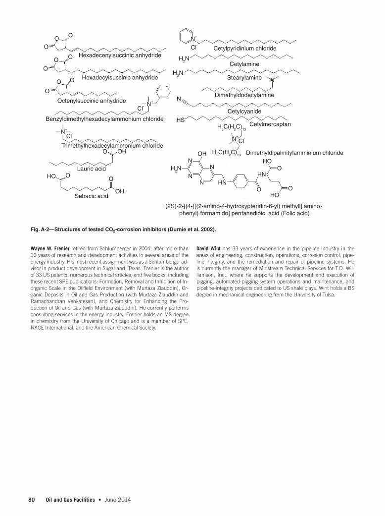
80 Oil and Gas Facilities • June 2014 June 2014 • Oil and Gas Facilities PB
Wayne W. Frenier retired from Schlumberger in 2004, after more than 30 years of research and development activities in several areas of the energy industry. His most recent assignment was as a Schlumberger ad-visor in product development in Sugarland, Texas. Frenier is the author of 33 US patents, numerous technical articles, and five books, including these recent SPE publications: Formation, Removal and Inhibition of In-organic Scale in the Oilfield Environment (with Murtaza Ziauddin), Or-ganic Deposits in Oil and Gas Production (with Murtaza Ziauddin and Ramachandran Venkatesan), and Chemistry for Enhancing the Pro-duction of Oil and Gas (with Murtaza Ziauddin). He currently performs consulting services in the energy industry. Frenier holds an MS degree in chemistry from the University of Chicago and is a member of SPE, NACE International, and the American Chemical Society.
David Wint has 33 years of experience in the pipeline industry in the areas of engineering, construction, operations, corrosion control, pipe-line integrity, and the remediation and repair of pipeline systems. He is currently the manager of Midstream Technical Services for T.D. Wil-liamson, Inc., where he supports the development and execution of pigging, automated-pigging-system operations and maintenance, and pipeline-integrity projects dedicated to US shale plays. Wint holds a BS degree in mechanical engineering from the University of Tulsa.
O
O
O
O O
O
O
O
N+
N+
N
N
HS
N+
N+Cl-
Cl-
Cl-
Cl-
O
OH
OH
H2N
H2N
H2NN
N
N
N HN
HO
HO
(2S)-2-[(4-{[(2-amino-4-hydroxypteridin-6-yl) methyll] amino} phenyl) formamido] pentanedioic acid (Folic acid)
Cetylpyridinium chloride
Cetylamine
Stearylamine
Dimethyldodecylamine
Cetylcyanide
Cetylmercaptan
Dimethyldipalmitylamminium chloride
Hexadecenylsuccinic anhydride
Hexadecylsuccinic anhydride
Octenylsuccinic anhydride
Benzyldimethylhexadecylammonium chloride
Trimethylhexadecylammonium chloride
Lauric acid
Sebacic acidO O
OHN
OH H3C(H2C)13
H3C(H2C)13
HO
O
O O
Fig. A-2—Structures of tested CO2-corrosion inhibitors (Durnie et al. 2002).