Embed Size (px)
Citation preview

Air Cooled Condenser
Catalog 400.10 April 1996
3/4 thru 216 Nominal tons Vertical and Horizontal

General
Russell's Multicon condensers are designed to provide the optimum in heat transfer efficiency and are constructed for years of reliable performance. Available in 85 sizes, the Multicon condensers range in capacity from 3/4 to 216 nominal tons. Only the highest grades of commercially available aluminum, copper and galvanized steel go into the manufacturing of each Multicon air cooled condenser. After assembly every unit is closely inspected before it is securely crated to ensure trouble free installation and operation.
VAC MODEL — 5 to 19 nominal tons
•Available in 10 sizes • Direct drive • Vertical discharge • Optional horizontal discharge • Galvanized steel casing
RAC MODEL — 3/4 to 3 nominal tons
• Available in 5 sizes • Direct drive • Vertical or horizontal discharge • Galvanized steel casing
VAC MODEL — 22 to 216 nominal tons
• Available in 35 sizes • Direct drive 1140 RPM motors • Vertical discharge • Optional horizontal discharge • Galvanized steel casing
VEQ MODEL — 21 to 189 nominal tons
• Available in 35 sizes • Direct drive 850 RPM motors • Vertical discharge • Optional horizontal discharge • Galvanized steel casing

Features
COILS • Coil fins are manufactured from die formed corrugated aluminum.
The tubes are seamless 1/2" OD copper, arranged in a staggered pattern and mechanically expanded into the fins and tube sheets for optimum heat transfer efficiency.
• Headers are produced from heavy wall copper tubing, and are brazed to the coil using a high temperature brazing process.
• All coils are leak tested in an illuminated test tank at a pressure of 380 psig.
FAN / MOTOR • All fans are sized for maximum energy efficiency, minimum noise, and are individually
balanced to minimized vibration. • All models have die stamped aluminum blades riveted to a galvanized steel spider
assembly. • Fan guards are fabricated from heavy gauge steel rod and epoxy coated. • On multiple fan units, all fans are baffled to prevent short-circuiting of air during fan cycling. • All VAC and VEQ motor assemblies are supported in all-welded, heavy gauge wire
support structures. The wire structures are zinc-chromate coated for corrosion protection. • All motors have built in thermal protection. • Motors are available in the following voltages:
RAC -115/230/1/60, shaded pole VAC 5 thru 19 - 208/230/1/60, psc. Optional 460/1/60, 230/3/60 or 460/3/60. VAC 22 thru 216, VEQ 21 thru 189 - 208/230/460/3/60, open drip-proof
OPTIONS • Fan cycling control— available with contactors and either ambient or head pressure sensors. Fan cycling, on double width VAC & VEQ
motors can be supplied with individual contactors. • Flooded condenser control— available using three-way modulating valves controlled by discharge pressure. Valves are shipped
mounted. • Motor fusing— available on all models. Motors can be fused individually or in pairs on double width units (not U.L listed). • Sub-cooling section — available as an integral part of the condenser. • Fins — available in four options; aluminum, copper, polyester coated aluminum, and baked phenolic coated aluminum. • Multiple system circuiting— available on RAC, VAC and VEQ models. (See page 6 for details.) • Variable speed fan control — can be supplied on VAC models 5 thru 19. • Hinged venturipanel(s) — can be provided on all VAC and VEQ models to allow for easy coil cleaning of the coil fins and quick access
to the fan and motor assembly. • Horizontal air discharge—available upon request. Contact Russell for details. • Built-in power disconnect switch — available on all VAC and VEQ models.

Selections
For the proper selection of an air cooled condenser it is necessary to know the total heat rejection of the condenser. The Total Heat Rejection (THR) is equivalent to the sum of the Net Refrigerating Effect (NRE) plus the heat of compression added by the compres-sor. The amount of heat added to the refrigerant will depend on the style of compressor, open or suction cooled, and the operating conditions of the system. Whenever the THR values are available from the compressor manufacturer they should be used in selecting a condenser. For those cases in which the THR data is unavailable it can be quickly estimated using the following equation and the appropriate factor from Tables 1 or 2. Eq. (1) THR = Compressor Capacity x Heat Rejection Factor In those cases where the refrigeration system is of a multiple or cascade style, the following equations should be used to estimate the total heat rejection. Open Compressor Eq. (2) THR = Compressor Capacity + (2545 x BHP) Suction Cooled Compressor Eq. (3) THR = Compressor Capacity + (3413 x KW) Altitude at which a condenser is to operate will also affect its capacity. In order to correctly select a condenser at a specific altitude, use the following equation and the appropriate correction factor from Table 3. Eq. (4) THR Corr. = THR Design x Altitude Correction Factor Selection Example Given: Altitude ........................................................5000 ft. Ambient Temperature .................................90°F Evaporator Temperature .............................20°F Maximum Condensing Temperature ...........110°F Refrigerant ..................................................R-22 Compressor Capacity (NRE) ......................225,000 BTUH Compressor Type .......................................Suction Cooled Assume compressor THR is not available
Calculate: 1. Total Heat Rejection 2. Design temperature difference 3. Russell condenser size 4. Actual system TD 5. Actual condensing temperature Solution: 1. Calculate the system THR from Table 2, a suction cooled
compressor, at 110°F condensing temperature and 20°F evap orator temperature, will have a heat rejection factor of 1.33. THR = Compressor Capacity x Heat Rejection Factor THR = 299,250 BTUH THR Corrected Altitude = THR x Altitude Corr. Factor THR Corrected Altitude = 336,656 BTUH
2. Design TD = Condensing Temp. - Ambient Temp. Design TD = 20°F
3. Select condenser size: From Table 5 on page 6 locate the R-22 section of the table. Then, using the TD of 20°F calculated in Step 2, go to the appropriate column and select a condenser whose THR equals or exceeds that of which we calculated in Step 1, 336,656, BTUH. A model VAC-35 with a THR of 357,100 BTUH will meet the required conditions.
4. Eq.(5) Actual TD = Design TD x Design THR Actual Condenser Capacity at Design TD
Actual TD = 18.9°F 5. Eq.(6) Actual Condensing Temp. = Actual TD + Ambient Temp.
Actual Condensing Temp. = 108.9°F
HEAT REJECTION FACTORS TABLE 1 - OPEN COMPRESSOR TABLE 2 - SUCTION COMPRESSOR EVAP. CONDENSING TEMPERATURE EVAP. CONDENSING TEMPERATURE TEMP. 90° 100 105° 110° 115° 120° 125° 130° TEMP. 90° 100 105 110° 115° 120° 125° 130° -40° 1.45 1.48 1.52 1.56 1.58 1.61 -40° 1.67 1.71 1.75 1.79 1.84 1.90 -35° 1.42 1.45 1.47 1.51 1.54 1.57 -35° 1.63 1.67 1.70 1.73 1.78 1.83 -30° 1.39 1.41 1.44 1.47 1.50 1.53 -30° 1.58 1.62 1.65 1.68 1.72 1.77 -25° 1.37 1.39 1.41 1.44 1.46 1.49 1.52 -25° 1.54 1.58 1.60 1.64 1.67 1.71 1.76 -20° 1.34 1.37 1.39 1.41 1.43 1.45 1.48 1.51 -20° 1.49 1.53 1.56 1.58 1.63 1.66 1.70 1.75 -15° 1.31 1.34 1.37 1.38 1.40 1.42 1.45 1.47 -15° 1.46 1.50 1.52 1.54 1.58 1.62 1.65 1.69 -10° 1.28 1.31 1.33 1.37 1.38 1.40 1.42 1.45 -10° 1.42 1.46 1.48 1.50 1.53 1.57 1.62 1.64 0° 1.24 1.28 1.29 1.32 1.33 1.35 1.38 1.41 0° 1.36 1.40 1.42 1.44 1.47 1.50 1.54 1.56 10° 1.21 1.24 1.26 1.28 1.30 1.31 1.34 1.36 10° 1.31 1.34 1.36 1.38 1.40 1.43 1.47 1.49 20° 1.18 1.21 1.23 1.24 1.26 1.28 1.30 1.32 20° 1.26 1.29 1.31 1.33 1.35 1.37 1.40 1.43 30° 1.15 1.18 1.20 1.21 1.23 1.24 1.26 1.28 30° 1.22 1.25 1.26 1.28 1.30 1.32 1.35 1.37 40° 1.13 1.15 1.17 1.18 1.19 1.20 1.22 1.24 40° 1.18 1.21 1.22 1.24 1.25 1.27 1.30 1.32 50° 1.11 1.13 1.14 1.15 1.16 1.17 1.18 1.20 50° 1.14 1.17 1.18 1.20 1.21 1.23 1.25 1.27

Multi-circuiting
Russell's "Multicon" condensers have the inherent capability of allowing multiple refrigeration systems to be connected to a single condenser. Multi-circuiting is available on all RAC, VAC and VEQ model condensers. Each system on the condenser will be properly circuited to ensure even distribution of refrigerant throughout the circuits. Hot gas inlet and liquid outlet connections will be supplied for each system and will be properly identified for easy hookup on site. Please note that all system numbers must be in numerical sequence when ordering a multi-circuited condenser, as the connection on the condenser will be installed in numerical sequence. The number 1 circuit will be located at the left hand side of the header when facing the header end of the unit, with all other circuits following the sequence to the right. An example is provided to assist you in the selection of a multi-circuited condenser. Our application engineering department is also available to make the selection for your specific requirements. For copies of the multi-circuiting worksheets contact your local Russell representative and request form MC-4.
EXAMPLE
Given: Number of refrigerant systems. Compressor type - Suction cooled Altitude - 5000 feet Ambient - 95°F See Table 4 for Refr. Type, Evap. Temp., Condensing Temp, and Compressor Capacity for each system. Calculation: 1. As the THR is not given, select for each system the heat
rejection factor for the appropriate style of compressor from Table 1 or 2, and enter the factors in column F. Note: If the compressor's THR is available enter it in column E and enter 1.0 in column F.
2. From Table 3, select the altitude correction factor for 5000 feet elevation and enter it in column G.
3. Calculate the design TD using the following equation 7, and enter the design TD in column H. Eq. (7) TD design = Cond. Temp. - Design ambient.
4. Calculate the corrected THR at 1 °F by multiplying columns E, F and G, then divide the total by column H. Enter the result in column I.
5. Calculate the total required THR by adding the values in column I and entering the result at the bottom of the column. Example: THR = 22685 BTUH
6. Using R-22 and the THR from the bottom of column I, select a model from the 1 °F TD column of Table 5. Example: A Model VAC-55 with a THR of 25.4 using R-22 will provide the required THR.
7. From Table 11 select the capacity per circuit for the model selected in step 6 and enter it in column J.
8. Calculate the number of circuits required by dividing column I by column J. Enter the result in column K.
9. In column K assign the number of circuits required for each system. If the fractional part of the circuits in column K is less than 10% of the whole number, then drop the fraction and enter the whole number in column L. When the fraction is greater than 10% of the whole number, then round it off to the next whole number and enter it in column K.
10. Total column L and enter it at the bottom of the column. If the total number of circuits exceeds the maximum number of circuits available, for the condenser model selected (see Table 10), then it may be necessary to allow a higher condens ing temperature for one or two of the systems. If this is not acceptable it will be necessary to select a larger condenser and recalculate the circuits by repeating steps 6 through 10.
11. Calculate the actual TD for each circuit using equation 8. Eq. (8) TD Actual = TD Design x No. of Circ. Req'd. No.
of Circ. assigned
TABLE 3 - ALTITUDE CORRECTION FACTOR (FT) Altitude Sea Level 1000 2000 3000 4000 5000 6000 7000 8000 9000 10000
Factor 1.0 1.029 1.052 1 .076 1.101 1.125 1.151 1.177 1.204 1.231 1.260 TABLE 4 (A) (B) (C) (D) (E) X (F) X (G) + (H) = (I) ÷ (J) = (K) (L) (M)
SYST. NO.
REFR. TYPE
EVAP. TEMP
. COND. TEMP.
COMP. CAP.
BTUH NRE
COMP. HEAT
REJ. FACT. (Table 1 or 2)
ALTITUDE
CORR. FACTOR (Table 3)
DESIGN T.D.
CORRECTED THR
BTUH/1T.D.
CAP. PER CIRCUIT
BTUH/1˚T.D. (Table 11)
NO. CIRC.
REQ'D
NO. CIRC.
REQ'D
ACTUAL T.D.
1 22 20 115 1 5000 X 1.35 X 1.125 ÷ 20 = 1139 ÷ 968 = 1.2 2 12.0 2 22 10 110 26000 X 1.38 X 1.125 ÷ 15 = 2691 ÷ 968 = 2.8 3 14.0 3 22 50 125 240000 X 1.25 X 1.125 ÷ 30 = 11250 ÷ 1017 = 11.1 11 30.3
4 502 -10 110 34000 X 1.50 X 1.125 ÷ 15 = 3825 ÷ 999 = 3.8 4 14.3 5 502 -25 105 21000 X 1.60 X 1.125 ÷ 10 = 3780 ÷ 999 = 3.8 4 9.5 TOTAL 22685 24

Capacities
R-404A REFRIGERANT* R-22 REFRIGERANT T.D. T.D.
MODEL NUMBER
10° 20° 30° 10° 20° 30° "RAC" MODELS
R-404A REFRIGERANT* R-22 REFRIGERANT
RAC 1 5.6 11.1 16.7 5.7 11.3 17.0RAC 1-1/2 8.0 16.1 24.1 8.2 16.4 24.6RAC 2 10.3 20.6 31.0 10.5 21.0 31.5RAC 3 15.1 30.1 45.2 15.3 30.7 46.0
"VAC" SINGLE FAN WIDTH MODELS VAC 5 26.6 53.3 79.9 27.1 54.2 81.3VAC 6 29.2 58.4 87.6 29.7 59.5 89.2VAC 7 36.4 72.9 109.3 37.1 74.2 111.2VAC 8 43.4 86.9 130.3 44.2 88.4 132.7VAC 9 46.7 93.5 140.2 47.6 95.2 142.7VAC 11 56.0 112.1 168.1 57.0 114.1 171.1VAC 13 73.7 147.4 221.1 75.0 150.0 225.0VAC 15 77.6 155.2 232.8 79.0 158.0 237.0VAC 17 91.3 182.7 274.0 93.0 185.9 278.9VAC 19 96.3 192.6 288.9 98.0 196.0 294.0VAC 22 115.6 231.2 346.8 117.6 235.3 352.9VAC 25 123.8 247.7 371.5 126.0 252.1 378.1VAC 29 134.2 268.3 402.5 136.6 273.1 409.7VAC 31 149.6 299.3 448.9 152.3 304.6 456.9VAC 35 175.4 350.9 526.3 178.6 357.1 535.7VAC 42 201.2 402.5 603.7 204.8 409.7 614.5VAC 48 225.0 450.0 674.9 229.0 458.0 687.0VAC 55 249.7 499.5 749.2 254.2 508.4 762.6VAC 58 268.3 536.6 805.0 273.1 546.2 819.3VAC 62 299.3 598.6 897.8 304.6 609.2 913.8VAC 67 332.3 664.6 996.9 338.2 676.5 1014.7VAC 72 350.9 701.8 1052.6 357.1 714.3 1071.4VAC 79 374.4 748.8 1123.2 380.7 761.3 1142.0VAC 84 415.6 1039.0 1246.7 422.5 845.0 1267.5VAC 90 438.9 877.8 1316.8 446.3 892.5 1338.8VAC 96 449.1 898.2 1347.3 456.8 913.6 1370.4VAC 101 498.5 997.1 1495.6 507.0 1014.0 1521.0VAC 108 526.7 1053.5 1580.2 535.6 1071.2 1606.8
"VAC" DOUBLE FAN WIDTH MODELS VAC 59 268.3 536.6 805.0 273.1 546.2 819.3VAC 63 299.3 598.6 897.8 304.6 609.2 913.8VAC 68 332.3 664.6 996.9 338.2 676.5 1014.7VAC 73 350.9 701.8 1052.6 357.1 714.3 1071.4VAC 83 402.5 805.0 1207.4 409.7 819.3 1229.0VAC 95 459.2 918.5 1377.7 467.4 934.9 1402.3VAC 102 498.5 996.9 1495.4 507.3 1014.7 1522.0VAC 116 536.6 1073.3 1609.9 546.2 1092.4 1638.6VAC 127 598.6 1197.1 1795.7 609.2 1218.5 1827.7VAC 134 664.6 1329.2 1993.8 676.5 1352.9 2029.4VAC 144 701.8 1403.5 2105.3 714.3 1428.5 2142.8VAC 158 748.8 1497.6 2246.4 761.3 1522.6 2283.9VAC 168 831.1 1662.9 2493.3 845.0 1690.0 2535.0VAC 180 877.8 1755.7 2633.5 892.5 1785.0 2677.5VAC 190 898.3 1796.5 2694.9 913.6 1827.2 2740.8VAC 202 997.1 1994.2 2991.3 1014.0 2028.0 3042.0VAC 216 1053.5 2107.0 3160.5 1071.2 2142.4 3213.6
R-404A REFRIGERANT R-22 REFRIGERANT MODEL NUMBER T.D.
10°
20° T.D.
30° 10°
20°
30°
"VEQ" SINGLE FAN WIDTH MODELS VEQ-21 101.0 202.1 303.1 102.9 205.8 308.7VEQ-23 108.3 216.5 324.8 110.2 220.5 330.7VEQ-24 117.4 234.7 352.1 119.5 239.0 358.5VEQ-27 130.8 261.7 392.5 133.2 266.5 399.7VEQ-32 153.4 306.9 400.3 156.3 312.5 468.8VEQ-36 176.0 351.9 527.9 179.2 358.4 537.5VEQ-40 196.7 393.5 590.2 200.3 400.7 601.0VEQ-45 218.4 436.8 655.2 222.4 444.8 667.2VEQ-49 234.6 469.3 703.9 238.9 477.9 716.8VEQ-54 261.7 523.4 785.1 266.5 533.0 799.5VEQ-60 290.6 581.1 871.7 295.9 591.8 887.7VEQ-64 306.8 613.6 920.4 312.4 624.8 937.3VEQ-69 327.1 654.2 981.2 333.1 666.1 999.2VEQ-75 363.0 726.0 1089.0 369.6 739.3 1108.9VEQ-80 383.4 766.9 1150.3 390.5 780.9 1171.4VEQ-81 392.5 784.9 1177.4 399.7 799.3 1199.0VEQ-89 435.6 871.2 1306.8 443.6 887.1 1330.7VEQ-94 460.2 920.3 1380.5 468.6 937.2 1405.8
"VEQ" DOUBLE FAN WIDTH MODELS VEQ-50 234.6 469.3 703.9 238.9 477.9 716.8VEQ-56 261.7 529.4 785.1 266.5 533.0 799.5VEQ-61 290.6 581.1 871.7 295.9 591.8 887.7VEQ-65 306.8 613.6 920.4 312.4 624.8 937.3VEQ-74 352.0 704.0 1056.0 358.4 716.9 1075.3VEQ-82 401.6 803.1 1204.7 408.9 817.8 1226.8VEQ-91 435.8 871.7 1307.5 443.8 887.7 1331.5VEQ-97 469.3 935.5 1407.8 477.9 955.7 1433.6VEQ-107 523.4 1046.8 1570.2 533.0 1066.0 1599.0VEQ-119 581.2 1162.4 1743.6 591.9 1183.7 1775.6VEQ-126 613.7 1227.4 1841.1 624.9 1249.9 1874.8VEQ-135 654.1 1308.1 1962.2 666.1 1332.1 1998.2VEQ-149 726.0 1452.0 2177.9 739.3 1478.6 2217.8VEQ-157 766.8 1533.6 2300.4 780.8 1561.7 2342.5VEQ-161 784.9 1569.8 2354.7 799.3 1598.6 2397.9VEQ-179 871.2 1742.3 2613.5 887.1 1774.3 2661.4VEQ-189 920.3 1840.6 2760.9 937.2 1874.4 2811.5
All capacities are in MBH. (MBH x 1000 = BtuH) For R-12,
134a ratings, multiply R-22 ratings by .95. For R-502, R-
507 ratings, use R-404A data.
NOTE: Standard circuiting of condensers are based on the following conditions:
25° T.D. for R-22 20° T.D. for R-12 & R-134a 15° T.D. for R-502 & R-404A
If T.D. used to select a given condenser is different from above conditions, those conditions must be given at time of order. This will allow for checking of the internal coil circuiting to optimize refrigerant pressure drop and performance for the specific application.
* Also R-507, R-502.
TABLE 5 – CONDENSER CAPACITIES (MBH)
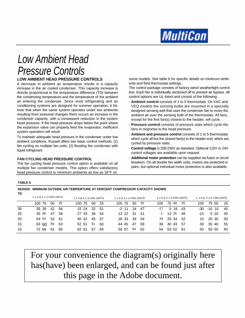
Low Ambient Head Pressure Controls LOW AMBIENT HEAD PRESSURE CONTROLS A decrease in ambient air temperature results in a capacity increase in the air cooled condenser. This capacity increase is directly proportional to the temperature difference (TD) between the condensing temperature and the temperature of the ambient air entering the condenser. Since most refrigerating and air conditioning systems are designed for summer operation, it fol-lows that when the same system operates under low ambients resulting from seasonal changes there occurs an increase in the condenser capacity, with a consequent reduction in the system head pressure. If the head pressure drops below the point where the expansion valve can properly feed the evaporator, inefficient system operation will result. To maintain adequate head pressure in the condenser under low ambient conditions, Russell offers two basic control methods: (1) fan cycling on multiple fan units; (2) flooding the condenser with liquid refrigerant.
FAN CYCLING HEAD PRESSURE CONTROL The fan cycling head pressure control option is available on all multiple fan condenser models. This option offers satisfactory head pressure control to minimum ambients as low as 18°F on
some models. See table 6 for specific details on minimum ambi-ents and field thermostat settings. The control package consists of factory wired weathertight control box. Each fan is individually sectioned off to prevent air bypass. All control options are UL listed and consist of the following: - Ambient control consists of 1 to 5 thermostats. On VAC and
VEQ models the sensing bulbs are mounted in a specially designed sensing well that uses the condenser fan to move the ambient air over the sensing bulb of the thermostats. All fans, except for the first fan(s) closest to the header, will cycle.
- Pressure control consists of pressure stats which cycle the fans in response to the head pressure.
- Ambient and pressure control consists of 1 to 5 thermostats which cycle all but the closest fan(s) to the header end, which are cycled by pressure stats.
- Control voltage is 208-230V as standard. Optional 115V or 24V control voltages are available upon request.
- Additional motor protection can be supplied via fuses or circuit breakers. On all double fan width units, motors are protected in pairs, but optional individual motor protection is also available.
TABLE 6
DESIGN MINIMUM OUTSIDE AIR TEMPERTURE AT PERCENT COMPRESSOR CAPACITY SHOWN TD
1 x 2 & 2 x 2 FAN UNITS
100 75 50 25 100 75 50 25 100 75 50 25 100 75 50 25 100 75 50 2530 35 39 42 56 15 24 32 51 -2 11 24 47 -17 0 16 43 -30 -10 10 4025 45 46 47 58 27 33 38 54 13 22 31 51 1 13 25 48 -10 5 20 4520 54 53 52 61 40 42 45 57 28 33 39 54 19 26 34 52 10 20 30 5015 63 60 56 63 52 51 51 60 44 45 47 58 36 40 43 57 30 35 40 5510 72 66 61 65 62 61 57 64 59 57 54 62 54 53 52 61 50 50 50 60
1 x 3 & 2 x 3 FAN UNITS 1 x 4 & 2 x 4 FAN UNITS 1 x 5 & 2 x 5 FAN UNITS 1 x 6 & 2 x 6 FAN UNITS
For your convenience the diagram(s) originally here has(have) been enlarged, and can be found just after
this page in the Adobe document.

FIGURE 1: VAC 5 THRU 19 single phase wiring without fan cycling control.
FIGURE 2: VAC 5 THRU 10 single phase wiring with fan cycling control.

FIGURE 3: VAC and VEQ phase wiring diagram for single row fan models with fan control.
FIGURE 4: VAC and VEQ phase wiring diagram for double row fan models with fan control.

Flooded-type Head Pressure Controls
The Russell condenser-flooding type of low ambient head pres-sure control consists of a combination of modulating pressure sensitive valve(s) mounted to the liquid and hot gas headers. (See Figures 5 and 6).
How the Valves Work Under the normal summer ambient design conditions the liquid side of the valve remains fully open and the hot-gas side fully closed, thus offering no interference with the design operation of the system. Under conditions of reduced loads and/or cold ambi-ent temperatures, the liquid side valve remains closed on start-up, causing the condenser to flood, thus reducing the effective con-denser surface area. Flooding continues until the condenser pressure reaches the pressure of the valve setting. The gas side valve, meanwhile is open, allowing a portion of the hot discharge
gas to flow directly into the receiver, maintaining in the receiver the high side pressure required for proper valve operation and preven-tion of compressor short-cycling. Once the desired pressure is reached in the condenser, the valve(s) modulate to maintain adequate high-side pressure regardless of outside ambient tem-perature conditions.
Valve Selection Because different refrigerants have varying pressure-tempera-ture characteristics and require different flow rates to produce given refrigeration tonnages, the valve ratings are based on net refrigerating tons at the evaporator. The psig settings are based on the type of refrigerant to be used in the system.
Select valves from Table 7. Do not undersize.
TABLE 7 FLOODED CONTROL VALVE SELECTIONS
MAXIMUM CAPACITY QUANTITY CONNECTION SIZE (2) MODEL TON(NRE)(1) OF
134a R-22 R-404A VALVES HOT-GAS LIQUIDA 15 21 12 1 7/8" ODS 5/8" ODS B 30 42 24 2 1-3/8"ODS 7/8" ODS C 45 63 36 3 1-5/8"ODS 1-1/8" ODS D 60 84 42 4 2-1/8"ODS 1 -3/8" ODS E 75 105 60 4 2-5/8" ODS 1-3/8" ODS F 90 126 72 6 2-5/8" ODS 1-5/8" ODS G 105 147 84 7 2-5/8" ODS 1 -5/8" ODS H 120 168 96 8 2-5/8" ODS 1-5/8" ODS I 135 189 108 9 2-5/8" ODS 1-5/8" ODS J 150 210 120 10 2-5/8" ODS 1 -5/8" ODS
Valve Installation
TABLE 8 VALVE SETTING (PSIG) REFRIGERANT LIQUID SIDE HOT GAS SIDE (3) 134a R-22 R-404A
100 180 180
20 20 20
Note:(1) Valve Capacity is based on net refrigeration effect at the evap-orator.
(2) See Figure 6 for pipe arrangement of multiple valve systems. (3) Pressure difference between discharge line and receiver. (4) When ordering a flooding control package, specify refrigeration
type by adding the refrigerant code to the valve model number. R-22 = 2, 134a = 1, R-502 = 2 (Example: C-2).
Figure 5 shows a typical installation of the condenser flooding low ambient control valve. Due to the tight seating arrangement of the valve, an auxiliary check valve in the liquid drain line to prevent refrigerant migration from the warm receiver to the cold condenser is not required under normal circumstances. Migration can occur only if the receiver pressure increases above the valve setting — where the receiver is located in an ambient of 90°F. or higher and the condenser in a lower ambient.
When condenser flooding valves are used, careful selection of the receiver is most important. Receiver pump-down capacity must equal or exceed the total refrigerant charge required in the system, including flooded condenser (see Page 10). Under all low ambient conditions, receivers should be located indoors in a warm area or, if outdoors, insulated and heated to a thermostatically controlled 60° to 65° temperature. Such heater(s) should be wired in parallel with the compressor crankcase heater, so it functions only during compressor off-cycle.
For your convenience the diagram(s) originally here has(have) been enlarged, and can be found
just after this page in the Adobe document.

HOT GAS IN HEAD PRESSURECONTROL VALVE

Refrigerant Charge REFRIGERANT CHARGE The summer design refrigerant charge necessary for effective system operation is the sum of operating charge for the evapora-tor, refrigerant piping (suction, liquid and discharge lines), condenser and receiver. The pump-down capacity of the receiver should be somewhat greater (10% to 15%) than the total refrigerant charge required. When using the Russell low ambient control system, additional refrigerant, over and above the summer design system charge, must be added to the system to allow for condenser flooding. The amount of this added charge is determined by the ambient in which the condenser will operate. Table 9 lists the total unit charge for all Russell single systems. For calculating the refrigerant charge for each compressor system or condenser follow the example below: Given: VAC-55 (3 fans long) Design TD: 20°F Flooded control, no fan cycling R-22 Minimum design ambient: 40°F
Solution: 1. Select the total charge from Table 9 for a VAC-55
condenser, using R-22 refrigerant.
2. Select the appropriate correction factor from Table 10 for the ambient temperature range at time of charging.
3. Use Equation (9) to calculate the total unit charge for the condenser.
Eq.9: System Cond. Chg. = total unit charge x correction factor System Cond. Chg. = 36.4 x 3.0 System Cond. Chg. = 109.2 Ibs.
For multiple system condensers use the same procedure above, except in step 1 use the charge per circuit value from Table 9 instead of the total unit charge and multiply by the number of circuits for each system.
For refrigerant line sizing see Pages 26-29 of Russell's refrigeration engineering manual.
TABLE 9 REFRIGERANT WEIGHTS, TOTAL AND PER CIRCUIT (LBS)
R-404A R-22 MODEL MAX CHARGE TOTAL CHARGE TOTAL
CIR PER UNIT PER UNIT QTY CIRCUIT CHARGE CIRCUIT CHARGE"RAC" MODELS
RAC 3/4 12 0.11 1.4 0.11 1.4RAC 1 12 0.21 2.5 0.21 2.5RAC 1-1/2 12 0.18 2.2 0.18 2.2RAC 2 12 0.27 3.3 0.27 3.3RAC 3 12 0.37 4.4 0.37 4.4"VAC" SINGLE FAN WIDTH MODELS VAC 5 30 0.11 3.5 0.11 3.3VAC 6 30 0.11 3.5 0.11 3.3VAC 7 22 0.28 6.1 0.23 6.0VAC 8 30 0.23 7.0 0.22 6.6VAC 9 30 0.23 7.0 0.22 6.6VAC 11 30 0.22 6.6 0.21 6.2VAC 13 22 0.45 9.8 0.43 9.4VAC 15 22 0.45 9.8 0.43 9.4VAC 17 30 0.44 13.1 0.42 12.5VAC 19 25 0.65 16.3 0.63 15.7VAC 22, VEQ 21 22 0.68 15.0 0.67 14.7VAC 25, VEQ 23 22 0.68 15.0 0.67 14.7VAC 29, VEQ 24 22 0.68 15.0 0.67 14.7VAC 31, VEQ 27 30 0.67 20.2 0.66 19.7VAC 35, VEQ 32 25 1.00 24.8 0.98 24.6VAC 42, VEQ 36 22 1.01 22.1 0.99 21.9VAC 48, VEQ 40 30 0.98 29.5 0.97 29.1VAC 55, VEQ 45 25 1.47 36.7 1.46 36.4VAC 58, VEQ 49 22 1.34 29.4 1.32 29.0VAC 62, VEQ 54 30 1.31 39.4 1.29 38.6VAC 67, VEQ 60 25 1.96 48.9 1.93 48.3VAC 72, VEQ 64 25 1.96 48.9 1.93 48.3VAC 79, VEQ 69 30 1.63 48.9 1.60 48.1VAC 84, VEQ 75 25 2.44 61.1 2.40 60.1VAC 90, VEQ 80 25 2.44 61.1 2.40 60.1VAC 96, VEQ 81 30 1.96 58.6 1.93 57.7VAC 101, VEQ 89 25 2.93 73.2 2.88 72.1VAC 108, VEQ 94 25 2.93 73.2 2.88 72.1
R-404A R-22
MODEL MAX CIR QTY
CHARGE TOTAL CHARGE TOTAL PER UNIT PER UNIT CIRCUIT CHARGE CIRCUIT CHARGE
"VAC" DOUBLE FAN WIDTH MODELS VAC 59, VEQ 50 44 0.67 29.8 0.67 29.5VAC 63, VEQ 56 60 0.67 39.7 0.66 39.3VAC 68, VEQ 61 50 1.00 49.4 0.98 49.1VAC 73, VEQ 65 50 1.00 49.4 0.98 49.1VAC 83, VEQ 74 44 1.00 44.3 0.99 43.7VAC 95, VEQ 82 60 1.00 58.9 0.97 58.3VAC 102, VEQ 91 50 1.47 73.6 1.46 72.8VAC 116, VEQ 97 44 1.34 58.9 1.32 57.9VAC 127, VEQ 107 60 1.31 78.7 1.29 77.2VAC 134, VEQ 119 50 1.97 98.3 1.93 96.5VAC 144, VEQ 126 50 1.97 98.3 1.93 96.5VAC 158, VEQ 135 60 1.64 98.1 1.60 96.2VAC 168, VEQ 149 50 2.46 122.8 2.40 120.2VAC 180, VEQ 157 50 2.46 122.8 2.40 120.2VAC 190, VEQ 161 60 1.95 117.7 1.93 115.4VAC 202, VEQ 179 50 2.94 147.1 2.88 144.2VAC 216, VEQ 189 50 2.94 147.1 2.88 144.2
For R-12 circuit or total charge multiply the R-22 values by 1.109. For R-502 circuit or total charge use R-404A data.

Refrigerant ChargeTABLE 10
60° 50° 40° 30° 20° 10° 0° -10° -20°
ALL SIZES
30° 25° 20° 15° 10°
1.07 1.61 2.15 2.68 3.22
1.88 2.28 2.68 3.09 3.49
2.36 2.68 3.00 3.33 3.65
2.68 2.95 3.22 3.49 3.75
2.92 3.15 3.36 3.59 3.83
3.09 3.29 3.49 3.70 3.88
3.22 3.40 3.57 3.75 3.93
3.33 3.49 3.65 3.81 3.97
3.43 3.56 3.70 3.85 4.00
WITH FAN CYCLING
TWO FAN CELLS LONG
30° 25° 20° 15° 10°
1.03 1.05 1.05 1.60 2.50
1.05 1.07 1.60 2.28 2.95
1.07 1.60 2.15 2.68 3.22
1.60 2.06 2.50 2.95 3.41
1.99 2.37 2.76 3.15 3.53
2.28 2.60 2.95 3.29 3.60
2.50 2.80 3.11 3.41 6.69
2.68 2.95 3.22 3.49 3.75
2.83 3.09 3.32 3.62 3.81
THREE FAN CELLS LONG
30° 25° 20° 15° 10°
1.01 1.01 1.04 1.06 1.78
1.01 1.03 1.06 1.37 2.40
1.03 1.05 1.27 2.03 2.78
1.05 1.15 1.77 2.40 3.05
1.07 1.59 2.04 2.68 3.22
1.37 1.92 2.40 2.88 2.34
1.77 2.19 2.62 3.05 3.46
2.03 2.40 2.78 3.17 3.53
2.24 2.58 2.92 3.28 3.61
FOUR FAN CELLS LONG
30° 25° 20° 15° 10°
1.01 1.01 1.02 1.05 1.23
1.01 1.01 1.04 1.07 2.01
1.01 1.03 1.07 1.54 2.46
1.02 1.05 1.23 2.01 2.75
1.04 1.07 1.67 2.33 2.98
1.06 1.43 2.01 2.58 3.15
1.23 1.74 2.33 2.75 3.27
1.54 2.01 2.46 2.92 3.37
1.79 2.21 2.62 3.05 3.45
FIVE FAN CELLS LONG
30° 25° 20° 15° 10°
1.00 1.00 1.00 1.01 1.01
1.00 1.00 1.00 1.01 1.65
1.00 1.00 1.00 1.12 2.13
1.00 1.00 1.01 1.63 2.46
1.00 1.00 1.20 2.03 2.72
1.01 1.01 1.63 2.32 2.92
1.01 1.04 2.07 2.52 3.10
1.06 1.63 2.19 2.72 3.23
1.36 1.85 2.36 2.87 3.33
SIX FAN CELLS LONG
30° 25° 20° 15° 10°
1.00 1.00 1.00 1.00 1.00
1.00 1.00 1.00 1.00 1.35
1.00 1.00 1.00 1.00 1.83
1.00 1.00 1.00 1.18 2.19
1.00 1.00 1.08 1.71 2.37
1.00 1.00 1.21 2.04 2.69
1.00 1.08 1.79 2.26 2.94
1.00 1.25 1.94 2.52 3.11
1.09 1.51 2.10 2.74 3.23
- REFRIGERANT CHARGE CORRECTION FACTOR WITH FLOODED-TYPE HEAD PRESSURE CONTROLDESIGN
TDMINIMUM DESIGN AMBIENT TEMPERATURE
WITHOUT FAN CYCLING
UNIT LENGTH*

R-404A R-22 R-404A R-22 R-404A R-22
"RAC" MODELSRAC 3/4 36 37 VAC 59 610 621 VEQ-21 459 468RAC 1 47 47 VAC 63 499 508 VEQ-23 492 501RAC 1-1/2 67 68 VAC 68 665 676 VEQ-24 537 543RAC 2 86 88 VAC 73 702 714 VEQ-27 436 444RAC 3 126 128 VAC 83 915 931 VEQ-32 614 625
VAC 95 765 779 VEQ-36 786 814VAC 5 89 90 VAC 102 997 1015 VEQ-40 656 668VAC 6 97 99 VAC 116 1220 1241 VEQ-45 873 890VAC 7 165 169 VAC 127 997 1015 VEQ-49 1067 1086VAC 8 145 147 VAC 134 1329 1353 VEQ-54 873 888VAC 9 156 159 VAC 144 1404 1429 VEQ-60 1163 1184VAC 11 187 190 VAC 158 1248 1269 VEQ-64 1227 1250VAC 13 335 341 VAC 168 1662 1690 VEQ-69 1090 1110VAC 15 353 359 VAC 180 1756 1785 VEQ-75 1452 1479VAC 17 304 310 VAC 190 1497 1523 VEQ-80 1534 1562VAC 19 385 392 VAC 202 1994 2028 VEQ-81 1309 1332VAC 22 526 535 VAC 216 2107 2142 VEQ-89 1743 1774VAC 25 563 573 VEQ-94 1841 1874VAC 29 610 621VAC 31 499 508 VEQ-50 533 543VAC 35 702 714 VEQ-56 437 444VAC 42 915 931 VEQ-61 581 592VAC 48 750 763 VEQ-65 614 625VAC 55 999 1017 VEQ-74 800 815VAC 58 1220 1241 VEQ-82 669 682VAC 62 998 1015 VEQ-91 872 888VAC 67 1329 1353 VEQ-97 1067 1086VAC 72 1404 1429 VEQ-107 872 888VAC 79 1248 1269 VEQ-119 1162 1184VAC 84 1663 1690 VEQ-126 1228 1250VAC 90 1750 1785 VEQ-135 1090 1110VAC 96 1498 1523 VEQ-149 1452 1479VAC 101 1995 2028 VEQ-157 1534 1562VAC 108 2107 2142 VEQ-161 1308 1332
VEQ-179 1743 1774For R-12 ratings, multiply R-22 ratings by .95. VEQ-189 1841 1874For R-502 ratings. use R-404A data.
TABLE 11CAPACITY PER CIRCUIT AT 1̊ F TD CAPACITY PER CIRCUIT AT 1° F TD
"VEQ" DOUBLE FAN WIDTH MODELS
MODEL BTUH / CIRCUIT
BTUH / CIRCUIT
"VEQ" SINGLE FAN WIDTH MODELS
CAPACITY PER CIRCUIT AT 1° F TD
"VAC" DOUBLE FAN WIDTH MODELS
"VAC" SINGLE FAN WIDTH MODELS
MODEL BTUH / CIRCUIT
BTHU / CIRCUIT
BTHU / CIRCUIT
BTUH / CIRCUIT MODEL

Physical Data
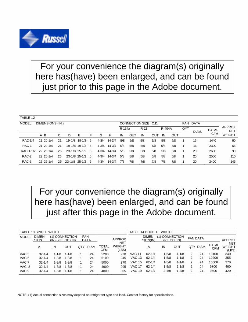
TABLE 12
CONNECTION SIZE O.D. FAN DATA MODEL DIMENSIONS (IN.) R-134a R-22 R-404A
A B C D E F G H IN OUT IN OUT IN OUT
QYT DIAM. TOTAL
CFM
APPROX NET
WEIGHT
RAC-3/4 21 RAC-1 21
RAC-1-1/2 22 RAC-2 22 RAC-3 22
20-1/4 20-1/4 26-1/4 26-1/4 26-1/4
21 19-1/8 21 19-1/8 25 23-1/8 25 23-1/8 25 23-1/8
19-1/2 19-1/2 25-1/2 25-1/2 25-1/2
6 6 6 6 6
4-3/4 4-3/4 4-3/4 4-3/4 4-3/4
14-3/4 14-3/4 14-3/4 14-3/4 14-3/4
5/8 5/8 5/8 5/8 5/8 5/8 5/8 5/8 7/8 7/8
5/8 5/8 5/8 5/8 7/8
5/8 5/8 5/8 5/8 7/8
5/8 5/8 5/8 5/8 7/8
5/8 5/8 5/8 5/8 7/8
1 1 1 1 1
16 16 20 20 20
1440 2300 2600 2500 2400
60 65 90
110 145
TABLE 13 SINGLE WIDTH MODEL DIMEN- (1) CONNECTION FAN
SION (IN) SIZE OD (IN) DATA A IN OUT QTY DIAM. TOTAL
CFM
APPROX NET
WEIGHT(LBS)
VAC 5 32-1/4 1-1/8 1-1/8 1 24 5200 220VAC 6 32-1/4 1-3/8 1-3/8 1 24 5100 245VAC 7 32-1/4 1-3/8 1-3/8 1 24 5000 270VAC 8 32-1/4 1-3/8 1-3/8 1 24 4900 295VAC 9 32-1/4 1-5/8 1-1/8 1 24 4800 305
TABLE 14 DOUBLE WIDTH
DIMEN- (1) CONNECTION SION(IN) SIZE OD (IN) FAN DATA
A IN OUT QTY DIAM. TOTAL
CFM
APPROX NET
WEIGHT(LBS)
VAC 11 62-1/4 1-5/8 1-1/8 2 24 10400 340 VAC 13 62-1/4 1-5/8 1-1/8 2 24 10200 355 VAC 15 62-1/4 1-5/8 1-1/8 2 24 10000 370 VAC 17 62-1/4 1-5/8 1-1/8 2 24 9800 400 VAC 19 62-1/4 2-1/8 1-3/8 2 24 9600 420
NOTE: (1) Actual connection sizes may depend on refrigerant type and load. Contact factory for specifications.
For your convenience the diagram(s) originally here has(have) been enlarged, and can be found
just prior to this page in the Adobe document.
For your convenience the diagram(s) originally here has(have) been enlarged, and can be found
just after this page in the Adobe document.


TABLE 15 SINGLE WIDTH
TABLE 16 DOUBLE WIDTH
DIMEN- (1) CONNECTION MODEL SIONS (IN) SIZE OD (IN) FAN DATA
A IN OUT QTY DIAM.
APPROX NET
TOTAL WEIGHT CFM (LBS)
VAC 22 98-1/4 1-5/8 1-1/8 2 30 22000 465VAC 25 98-1/4 1-5/8 1-1/8 2 30 21500 495VAC 29 98-1/4 1-5/8 1-1/8 2 30 21000 520VAC 31 98-1/4 1-5/8 1-1/8 2 30 20500 550VAC 35 98-1/4 2-1/8 1-1/8 2 30 20000 600VAC 42 146-1/4 2-1/8 1-1/8 3 30 32000 800VAC 48 146-1/4 2-1/8 1-1/8 3 30 31500 900VAC 55 146-1/4 2-1/8 1-3/8 3 30 31000 1000VAC 58 194-1/4 2-1/8 1-3/8 4 30 42000 1050VAC 62 194-1/4 2-1/8 1-3/8 4 30 41000 1100VAC 67 194-1/4 2-5/8 1-3/8 4 30 40500 1150VAC 72 194-1/4 2-5/8 1-3/8 4 30 40000 1200VAC 79 242-1/4 2-5/8 1-3/8 5 30 51250 1370VAC 84 242-1/4 2-5/8 1-3/8 5 30 50625 1430VAC 90 242-1/4 2-5/8 1-3/8 5 30 50000 1490VAC 96 290-1/4 2-5/8 1-3/8 6 30 61500 1690VAC 101 290-1/4 2-5/8 1-3/8 6 30 60750 1750VAC 108 290-1/4 2-5/8 1-3/8 6 30 60000 1830
DIMEN- (1) CONNECTION MODEL SIONS (IN) SIZE OD (IN) FAN DATA A IN OUT QTY DIAM.
APPROX NET
TOTAL WEIGHT CFM (LBS)
VAC 59 98-1/4 (2)1-5/8 (2)1-1/8 4 30 42000 1080VAC 63 98-1/4 (2)1-5/8 (2)1-1/8 4 30 41000 1140VAC 68 98-1/4 (2)1-5/8 (2)1-1/8 4 30 40500 1190VAC 73 98-1/4 (2)2-1/8 (2)1-1/8 4 30 40000 1240VAC 83 146-1/4 (2)2-1/8 (2)1-1/8 6 30 64000 1640VAC 95 146-1/4 (2)2-1/8 (2)1-1/8 6 30 63000 1840VAC 102 146-1/4 (2)2-1/8 (2)1-3/8 6 30 62000 2050VAC 116 194-1/4 (2)2-1/8 (2)1-3/8 8 30 84000 2150VAC 127 194-1/4 (2)2-1/8 (2)1-3/8 8 30 82000 2250VAC 134 194-1/4 (2)2-5/8 (2)1-3/8 8 30 81000 2350VAC 144 194-1/4 (2)2-5/8 (2)1-3/8 8 30 80000 2460VAC 158 242-1/4 (2)2-5/8 (2)1-3/8 10 30 102500 2800VAC 168 242-1/4 (2)2-5/8 (2)1-3/8 10 30 101250 2950VAC 180 242-1/4 (2)2-5/8 (2)1-3/8 10 30 100000 3075VAC 190 290-1/4 (2)2-5/8 (2)1-3/8 12 30 123000 3400VAC 202 290-1/4 (2)2-5/8 (2)1-3/8 12 30 121500 3620VAC 216 290-1/4 (2)2-5/8 (2)1-3/8 12 30 120000 3750
For your convenience the diagram(s) originally here has(have) been enlarged, and can be found
just prior to this page in the Adobe document.

Physical Data
TABLE 17 SINGLE WIDTH TABLE 18 DOUBLE WIDTH
MODEL DIMEN-SIONS(IN)
CONNECTION SIZE OD (IN) FAN DATA
A IN OUT QTY DIAM
APPROX NET
TOTAL WEIGHT CFM (LBS)
VEQ 21 98-1/4 1-5/8 1-1/8 2 30 16400 465VEQ 23 98-1/4 1-5/8 1-1/8 2 30 16000 495VEQ 24 98-1/4 1-5/8 1-1/8 2 30 15700 520VEQ 27 98-1/4 1-5/8 1-1/8 2 30 15300 550VEQ 32 98-1/4 2-1/8 1-1/8 2 30 14900 600VEQ 36 146-1/4 2-1/8 1-1/8 3 30 23900 800VEQ 40 146-1/4 2-1/8 1-1/8 3 30 23500 900VEQ 45 146-1/4 2-1/8 1-3/8 3 30 23100 1000VEQ 49 194-1/4 2-1/8 1-3/8 4 30 31300 1050VEQ 54 194-1/4 2-1/8 1-3/8 4 30 30600 1100VEQ 60 194-1/4 2-5/8 1-3/8 4 30 30200 1150VEQ 64 194-1/4 2-5/8 1-3/8 4 30 29800 1200VEQ 69 242-1/4 2-5/8 1-3/8 5 30 38200 1370VEQ 75 242-1/4 2-5/8 1-3/8 5 30 37800 1430VEQ 80 242-1/4 2-5/8 1-3/8 5 30 37300 1490VEQ 81 290-1/4 2-5/8 1-3/8 6 30 45900 1690VEQ 89 290-1/4 2-5/8 1-3/8 6 30 45300 1750VEQ 94 290-1/4 2-5/8 1-3/8 6 30 44800 1830
DIMEN-MODEL SIONS(IN)
(1) CONNECTION SIZE OD (IN) FAN DATA
A IN OUT QTY DIAM.
APPROX NET
VEQ 50 98-1/4 (2)1-5/8 (2)1-1/8 4 30 31300 1080VEQ 56 98-1/4 (2)1-5/8 (2)1-1/8 4 30 30600 1140VEQ 61 98-1/4 (2)1-5/8 (2)1-1/8 4 30 30200 1190VEQ 65 98-1/4 (2)2-1/8 (2)1-1/8 4 30 29800 1240VEQ 74 146-1/4 (2) 2-1/8 (2)1-1/8 6 30 47700 1640VEQ 82 146-1/4 (2)2-1/8 (2)1-1/8 6 30 47000 1840VEQ 91 146-1/4 (2)2-1/8 (2) 1-3/8 6 30 46200 2050VEQ 97 194-1/4 (2)2-1/8 (2) 1-3/8 8 30 62600 2150VEQ 107 194-1/4 (2)2-1/8 (2) 1-3/8 8 30 61100 2250VEQ 119 194-1/4 (2) 2-5/8 (2) 1-3/8 8 30 60400 2350VEQ 126 194-1/4 (2) 2-5/8 (2) 1-1/8 8 30 59700 2460VEQ 135 242-1/4 (2) 2-5/8 (2) 1-3/8 10 30 76400 2800VEQ 149 242-1/4 (2) 2-5/8 (2) 1-3/8 10 30 75600 2950VEQ 157 242-1/4 (2) 2-5/8 (2) 1-3/8 10 30 74600 3075VEQ 161 290-1/4 (2) 2-5/8 (2) 1-3/8 12 30 91800 3400VEQ 179 290-1/4 (2) 2-5/8 (2) 1-3/8 12 30 90600 3620VEQ 189 290-1/4 (2) 2-5/8 (2) 1-3/8 12 30 89600 3750
Electrical Data
TABLE 19 TOTAL MOTOR AMPS
MOTOR MOTOR MOTOR SINGLE PHASE THREE PHASE (1) 115V 208/230V 460V 208/230V 460V
MODEL QTY HP RPM
MODEL RAC RAC 3/4 1 1/6 1050 5.9 2.9 -- -- -- RAC 1 1 1/6 1050 5.9 2.9 -- -- -- RAC 1-1/2 1 1/6 1050 5.9 2.9 -- -- -- RAC 2 1 1/6 1050 5.9 2.9 -- -- -- RAC 3 1 1/6 1050 5.9 2.9 -- -- -- VAC 5 1 3/4 1075 -- 4.2 2.1 4.0 2.0
VAC 6 1 3/4 1075 -- 4.2 2.1 4.0 2.0 VAC 7 1 3/4 1075 -- 4.2 2.1 4.0 2.0 VAC 8 1 3/4 1075 -- 4.2 2.1 4.0 2.0 VAC 9 1 3/4 1075 -- 4.2 2.1 4.0 2.0 VAC 11 2 3/4 1075 -- 8.4 4.2 8.0 4.0 VAC 13 2 3/4 1075 -- 8.4 4.2 8.0 4.0 VAC 15 2 3/4 1075 -- 8.4 4.2 8.0 4.0 VAC 17 2 3/4 1075 -- 8.4 4.2 8.0 4.0 VAC 19 2 3/4 1075 -- 8.4 4.2 8.0 4.0
NOTES: Shaded areas indicate standard wiring arrangement. (1) All VAC 5 thru 19 models in this column have optional inherent 3 phase motors.

Electrical Data (Con’t)
TABLE 20 TABLE 21 MODEL MOTOR
QTY MOTOR
HP MOTOR
RPMTOTAL MOTOR AMPS
THREE PHASE208/230V 460V
VAC 22 2 1-1/2 1140 12.8 6.4 VAC 25 2 1-1/2 1140 12.8 6.4 VAC 29 2 1-1/2 1140 12.8 6.4 VAC 31 2 1-1/2 1140 12.8 6.4 VAC 35 2 1-1/2 1140 12.8 6.4
VAC 42 3 1-1/2 1140 19.2 9.6 VAC 48 3 1-1/2 1140 19.2 9.6 VAC 55 3 1-1/2 1140 19.2 9.6 VAC 58 4 1-1/2 1140 25.6 12.8 VAC 62 4 1-1/2 1140 25.6 12.8 VAC 67 4 1-1/2 1140 25.6 12.8
VAC 72 4 1-1/2 1140 25.6 12.8 VAC 79 5 1-1/2 1140 32.0 16.0 VAC 84 5 1-1/2 1140 32.0 16.0 VAC 90 5 1-1/2 1140 32.0 16.0
VAC 96 6 1-1/2 1140 38.4 19.2 VAC 101 6 1-1/2 1140 38.4 19.2 VAC 108 6 1-1/2 1140 38.4 19.2
TOTAL MOTOR AMPS MODEL
THREE PHASE 208/230V 460V
VEQ 21 2 1 850 10.6 5.3 VEQ 23 2 1 850 10.6 5.3 VEQ 24 2 1 850 10.6 5.3
VEQ 27 2 1 850 10.6 5.3 VEQ 32 2 1 850 10.6 5.3 VEQ 36 3 1 850 15.9 8.0 VEQ 40 3 1 850 15.9 8.0 VEQ 45 3 1 850 15.9 8.0 VEQ 49 4 1 850 21.2 10.6 VEQ 54 4 1 850 21.2 10.6
VEQ 60 4 1 850 21.2 10.6 VEQ 64 4 1 850 21.2 10.6 VEQ 69 5 1 850 26.5 13.3 VEQ 75 5 1 850 26.5 13.3 VEQ 80 5 1 850 26.5 13.3
VEQ 81 6 1 850 31.8 15.9 VEQ 89 6 1 850 31.8 15.9 VEQ 94 6 1 850 31.8 15.9
DOUBLE WIDTH FAN UNITS VAC 59 4 1-1/2 1140 25.6 12.8 VAC 63 4 1-1/2 1140 25.6 12.8
VAC 68 4 1-1/2 1140 25.6 12.8 VAC 73 4 1-1/2 1140 25.6 12.8 VAC 83 6 1-1/2 1140 38.4 19.2 VAC 95 6 1-1/2 1140 38.4 19.2 VAC 102 6 1-1/2 1140 38.4 19.2
VAC 116 8 1-1/2 1140 51.2 25.6 VAC 127 8 1-1/2 1140 51.2 25.6 VAC 134 8 1-1/2 1140 51.2 25.6 VAC 144 8 1-1/2 1140 51.2 25.6 VAC 158 10 1-1/2 1140 64.0 32.0
VAC 168 10 1-1/2 1140 64.0 32.0 VAC 180 10 1-1/2 1140 64.0 32.0 VAC 190 12 1-1/2 1140 76.8 38.4 VAC 202 12 1-1/2 1140 76.8 38.4 VAC 216 12 1-1/2 1140 76.8 38.4
DOUBLE WIDTH FAN UNITS VEQ 50 4 1 850 21.2 10.6 VEQ 56 4 1 850 21.2 10.6
VEQ 61 4 1 850 21.2 10.6 VEQ 65 4 1 850 21.2 10.6 VEQ 74 6 1 850 31.8 15.9 VEQ 82 6 1 850 31.8 15.9
VEQ 91 6 1 850 31.8 15.9 VEQ 97 8 1 850 42.4 21.2 VEQ 107 8 1 850 42.4 21.2 VEQ 119 8 1 850 42.4 21.2 VEQ 126 8 1 850 42.4 21.2 VEQ 135 10 1 850 53.0 26.5
VEQ 149 10 1 850 53.0 26.5 VEQ 157 10 1 850 53.0 26.5 VEQ 161 12 1 850 63.6 31.8 VEQ 179 12 1 850 63.6 31.8 VEQ 189 12 1 850 63.6 31.8
Russell reserves the right to make design changes and modifications to its product lines without prior notice.
MOTOR MOTOR MOTOR QTY HP RPM
Engineering Specifications
GENERAL Furnish and install as specified and as shown on plans, Russell type(s) (RAC, VAC, VEQ) air cooled condensers, arranged for (horizontal) (vertical) airflow. Condensers shall perform in accor-dance with (following schedule) (schedule on plan).
Each condenser shall consist of casing, condenser coil, direct driven propeller fan(s) driven by independent fan motor(s), ap-proved fan guard and mounting legs. All fan motors shall be factory wired to a common electrical control box.
Condensers shall be UL listed and each unit shall bear the UL seal.
CONDENSER COIL All condenser coils up to 3 nominal tons shall be 3/8" O.D. seamless copper tubing. All condenser coils larger than 3 nominal tons shall be fabricated of 1/2" O.D. seamless copper tubing. The tubes shall be mechanically expanded into full fin collars for permanent fin-tube contact. Fins shall be (aluminum) (copper) with die formed corrugations for optimum heat transfer capability. For additional corrosion protection the aluminum fins shall have a (polyester) (baked phenolic) coating.
Headers shall be seamless heavy wall copper tubing. No header shall be longer than 45" and no more than 2 headers can be manifolded together in the field.
Coils shall be leak tested at 380 psig in an illuminated water test tank.
HOUSING The casing of all RAC, VAC and VEQ models shall be constructed from heavy gauge galvanized steel, designed to provide maxi-mum casing rigidity as well as high corrosion protection. Tube sheets shall be mill finish aluminum and shall be designed in such a fashion to eliminate refrigerant tube leaks at the tube sheets.
FANS All fan blades shall be constructed of aluminum, riveted onto a galvanized steel spider.
Fans shall be designed for low tip speed and minimal noise.
All fans shall be statically balanced and factory run prior to shipping to ensure quiet, trouble-free operation.
All multiple fan condensers shall be supplied with full width baffles to prevent air bypass.
MOTORS All motors shall be equipped with inherent overload protection rated for group installation.
Motors for RAC models shall be shaded pole type with sleeve bearings.
Motors for VAC models 5 thru 19 shall be open drip-proof, permanent split capacitor type with permanently lubricated ball bearings.
Motors for VAC 22 thru 216 and VEQ models shall be open drip-proof 230/460/3/60 with permanently lubricated ball bearings. Motor shafts shall be keyed to the fan hub.
Motors shall be mounted in a zinc-chromate coated heavy steel rod support frame.
All units shall be factory wired into a junction box with all leads marked.
221 S. Berry Street • Brea, CA 92822-1030 • Telephone (714) 529-1935 • Fax (714) 529-7203 P/N 113343-015 REV212/93A5000