Embed Size (px)
Citation preview
Product Catalog
NQ Series
Portable and Remote Air-Cooled Condenser Chillers
4 to 43 Tons

Page Intentionally Blank
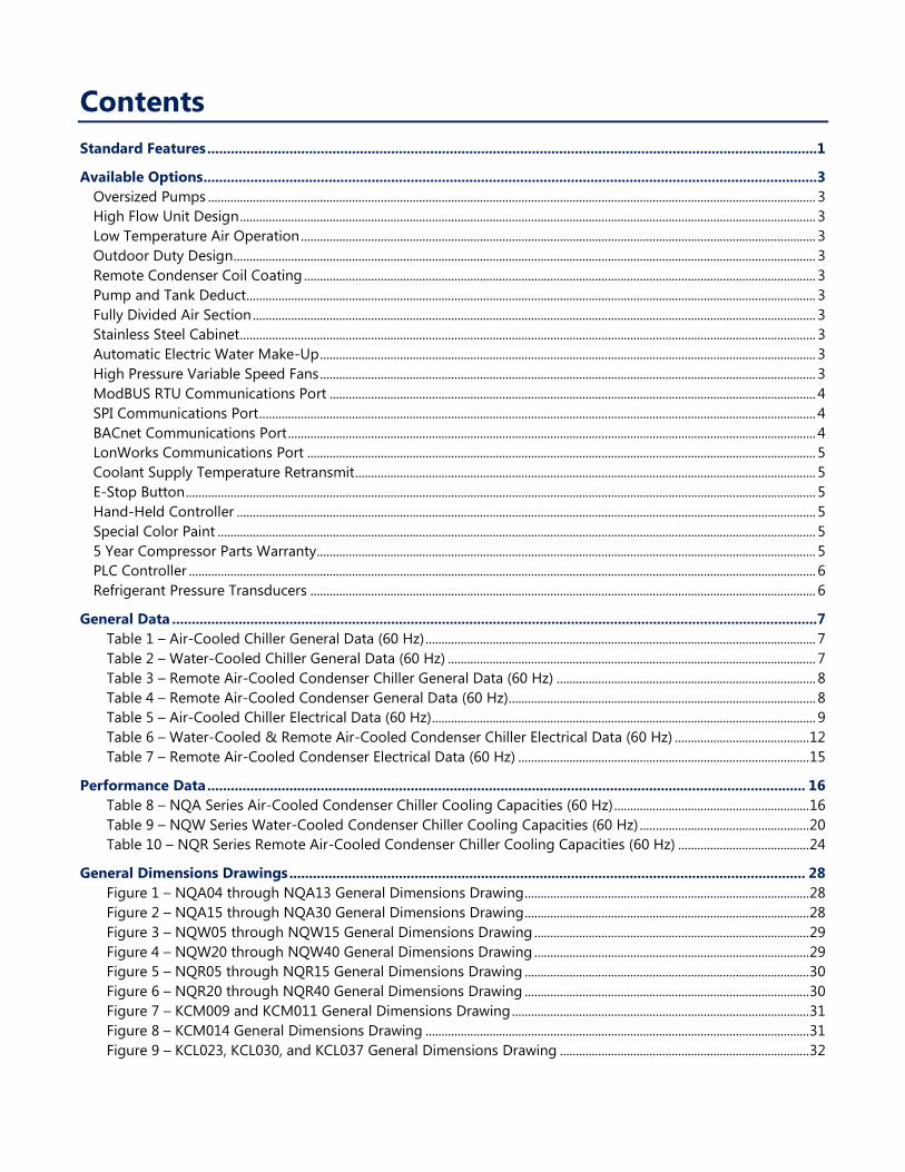
Contents
Standard Features ............................................................................................................................................................1
Available Options .............................................................................................................................................................3 Oversized Pumps .............................................................................................................................................................................................. 3 High Flow Unit Design .................................................................................................................................................................................... 3 Low Temperature Air Operation ................................................................................................................................................................. 3 Outdoor Duty Design ...................................................................................................................................................................................... 3 Remote Condenser Coil Coating ................................................................................................................................................................ 3 Pump and Tank Deduct.................................................................................................................................................................................. 3 Fully Divided Air Section ................................................................................................................................................................................ 3 Stainless Steel Cabinet .................................................................................................................................................................................... 3 Automatic Electric Water Make-Up ........................................................................................................................................................... 3 High Pressure Variable Speed Fans ........................................................................................................................................................... 3 ModBUS RTU Communications Port ........................................................................................................................................................ 4 SPI Communications Port .............................................................................................................................................................................. 4 BACnet Communications Port ..................................................................................................................................................................... 4 LonWorks Communications Port ............................................................................................................................................................... 5 Coolant Supply Temperature Retransmit ................................................................................................................................................ 5 E-Stop Button ..................................................................................................................................................................................................... 5 Hand-Held Controller ..................................................................................................................................................................................... 5 Special Color Paint ........................................................................................................................................................................................... 5 5 Year Compressor Parts Warranty............................................................................................................................................................ 5 PLC Controller .................................................................................................................................................................................................... 6 Refrigerant Pressure Transducers .............................................................................................................................................................. 6
General Data .....................................................................................................................................................................7 Table 1 – Air-Cooled Chiller General Data (60 Hz) .......................................................................................................................... 7 Table 2 – Water-Cooled Chiller General Data (60 Hz) ................................................................................................................... 7 Table 3 – Remote Air-Cooled Condenser Chiller General Data (60 Hz) ................................................................................. 8 Table 4 – Remote Air-Cooled Condenser General Data (60 Hz)................................................................................................ 8 Table 5 – Air-Cooled Chiller Electrical Data (60 Hz)........................................................................................................................ 9 Table 6 – Water-Cooled & Remote Air-Cooled Condenser Chiller Electrical Data (60 Hz) .......................................... 12 Table 7 – Remote Air-Cooled Condenser Electrical Data (60 Hz) ........................................................................................... 15
Performance Data ......................................................................................................................................................... 16 Table 8 – NQA Series Air-Cooled Condenser Chiller Cooling Capacities (60 Hz) ............................................................. 16 Table 9 – NQW Series Water-Cooled Condenser Chiller Cooling Capacities (60 Hz) ..................................................... 20 Table 10 – NQR Series Remote Air-Cooled Condenser Chiller Cooling Capacities (60 Hz) ......................................... 24
General Dimensions Drawings .................................................................................................................................... 28 Figure 1 – NQA04 through NQA13 General Dimensions Drawing ......................................................................................... 28 Figure 2 – NQA15 through NQA30 General Dimensions Drawing ......................................................................................... 28 Figure 3 – NQW05 through NQW15 General Dimensions Drawing ...................................................................................... 29 Figure 4 – NQW20 through NQW40 General Dimensions Drawing ...................................................................................... 29 Figure 5 – NQR05 through NQR15 General Dimensions Drawing ......................................................................................... 30 Figure 6 – NQR20 through NQR40 General Dimensions Drawing ......................................................................................... 30 Figure 7 – KCM009 and KCM011 General Dimensions Drawing ............................................................................................. 31 Figure 8 – KCM014 General Dimensions Drawing ........................................................................................................................ 31 Figure 9 – KCL023, KCL030, and KCL037 General Dimensions Drawing .............................................................................. 32
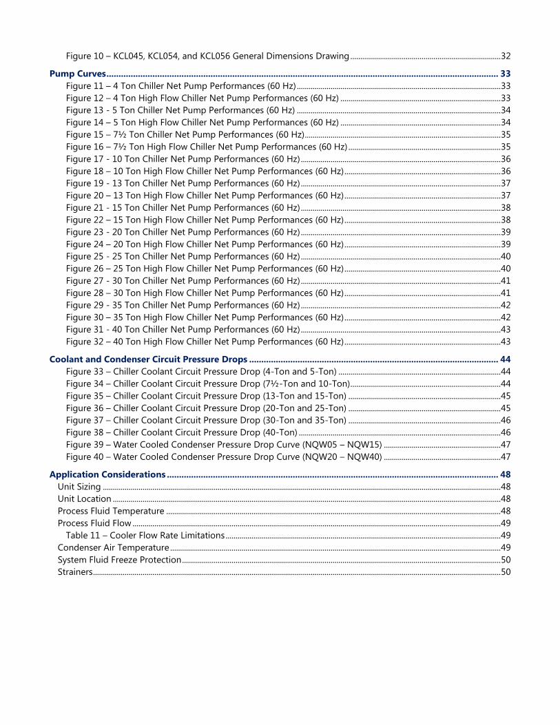
Figure 10 – KCL045, KCL054, and KCL056 General Dimensions Drawing ............................................................................ 32
Pump Curves .................................................................................................................................................................. 33 Figure 11 – 4 Ton Chiller Net Pump Performances (60 Hz) ....................................................................................................... 33 Figure 12 – 4 Ton High Flow Chiller Net Pump Performances (60 Hz) ................................................................................. 33 Figure 13 - 5 Ton Chiller Net Pump Performances (60 Hz) ....................................................................................................... 34 Figure 14 – 5 Ton High Flow Chiller Net Pump Performances (60 Hz) ................................................................................. 34 Figure 15 – 7½ Ton Chiller Net Pump Performances (60 Hz) ................................................................................................... 35 Figure 16 – 7½ Ton High Flow Chiller Net Pump Performances (60 Hz) ............................................................................. 35 Figure 17 - 10 Ton Chiller Net Pump Performances (60 Hz) ..................................................................................................... 36 Figure 18 – 10 Ton High Flow Chiller Net Pump Performances (60 Hz) ............................................................................... 36 Figure 19 - 13 Ton Chiller Net Pump Performances (60 Hz) ..................................................................................................... 37 Figure 20 – 13 Ton High Flow Chiller Net Pump Performances (60 Hz) ............................................................................... 37 Figure 21 - 15 Ton Chiller Net Pump Performances (60 Hz) ..................................................................................................... 38 Figure 22 – 15 Ton High Flow Chiller Net Pump Performances (60 Hz) ............................................................................... 38 Figure 23 - 20 Ton Chiller Net Pump Performances (60 Hz) ..................................................................................................... 39 Figure 24 – 20 Ton High Flow Chiller Net Pump Performances (60 Hz) ............................................................................... 39 Figure 25 - 25 Ton Chiller Net Pump Performances (60 Hz) ..................................................................................................... 40 Figure 26 – 25 Ton High Flow Chiller Net Pump Performances (60 Hz) ............................................................................... 40 Figure 27 - 30 Ton Chiller Net Pump Performances (60 Hz) ..................................................................................................... 41 Figure 28 – 30 Ton High Flow Chiller Net Pump Performances (60 Hz) ............................................................................... 41 Figure 29 - 35 Ton Chiller Net Pump Performances (60 Hz) ..................................................................................................... 42 Figure 30 – 35 Ton High Flow Chiller Net Pump Performances (60 Hz) ............................................................................... 42 Figure 31 - 40 Ton Chiller Net Pump Performances (60 Hz) ..................................................................................................... 43 Figure 32 – 40 Ton High Flow Chiller Net Pump Performances (60 Hz) ............................................................................... 43
Coolant and Condenser Circuit Pressure Drops ....................................................................................................... 44 Figure 33 – Chiller Coolant Circuit Pressure Drop (4-Ton and 5-Ton) .................................................................................. 44 Figure 34 – Chiller Coolant Circuit Pressure Drop (7½-Ton and 10-Ton) ............................................................................ 44 Figure 35 – Chiller Coolant Circuit Pressure Drop (13-Ton and 15-Ton) ............................................................................. 45 Figure 36 – Chiller Coolant Circuit Pressure Drop (20-Ton and 25-Ton) ............................................................................. 45 Figure 37 – Chiller Coolant Circuit Pressure Drop (30-Ton and 35-Ton) ............................................................................. 46 Figure 38 – Chiller Coolant Circuit Pressure Drop (40-Ton) ...................................................................................................... 46 Figure 39 – Water Cooled Condenser Pressure Drop Curve (NQW05 – NQW15) ........................................................... 47 Figure 40 – Water Cooled Condenser Pressure Drop Curve (NQW20 – NQW40) ........................................................... 47
Application Considerations ......................................................................................................................................... 48 Unit Sizing ......................................................................................................................................................................................................... 48 Unit Location .................................................................................................................................................................................................... 48 Process Fluid Temperature ......................................................................................................................................................................... 48 Process Fluid Flow .......................................................................................................................................................................................... 49
Table 11 – Cooler Flow Rate Limitations ........................................................................................................................................... 49 Condenser Air Temperature ....................................................................................................................................................................... 49 System Fluid Freeze Protection ................................................................................................................................................................. 50 Strainers .............................................................................................................................................................................................................. 50
1
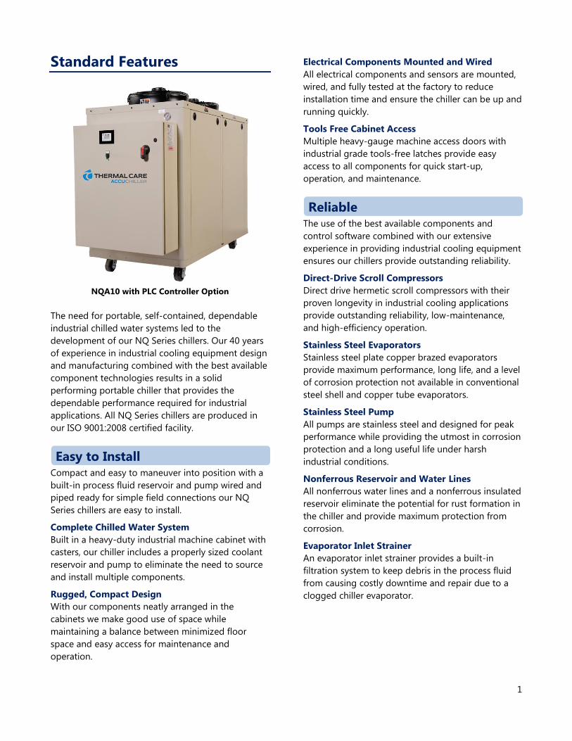
Standard Features
NQA10 with PLC Controller Option
The need for portable, self-contained, dependable
industrial chilled water systems led to the
development of our NQ Series chillers. Our 40 years
of experience in industrial cooling equipment design
and manufacturing combined with the best available
component technologies results in a solid
performing portable chiller that provides the
dependable performance required for industrial
applications. All NQ Series chillers are produced in
our ISO 9001:2008 certified facility.
Compact and easy to maneuver into position with a
built-in process fluid reservoir and pump wired and
piped ready for simple field connections our NQ
Series chillers are easy to install.
Complete Chilled Water System
Built in a heavy-duty industrial machine cabinet with
casters, our chiller includes a properly sized coolant
reservoir and pump to eliminate the need to source
and install multiple components.
Rugged, Compact Design
With our components neatly arranged in the
cabinets we make good use of space while
maintaining a balance between minimized floor
space and easy access for maintenance and
operation.
Electrical Components Mounted and Wired
All electrical components and sensors are mounted,
wired, and fully tested at the factory to reduce
installation time and ensure the chiller can be up and
running quickly.
Tools Free Cabinet Access
Multiple heavy-gauge machine access doors with
industrial grade tools-free latches provide easy
access to all components for quick start-up,
operation, and maintenance.
The use of the best available components and
control software combined with our extensive
experience in providing industrial cooling equipment
ensures our chillers provide outstanding reliability.
Direct-Drive Scroll Compressors
Direct drive hermetic scroll compressors with their
proven longevity in industrial cooling applications
provide outstanding reliability, low-maintenance,
and high-efficiency operation.
Stainless Steel Evaporators
Stainless steel plate copper brazed evaporators
provide maximum performance, long life, and a level
of corrosion protection not available in conventional
steel shell and copper tube evaporators.
Stainless Steel Pump
All pumps are stainless steel and designed for peak
performance while providing the utmost in corrosion
protection and a long useful life under harsh
industrial conditions.
Nonferrous Reservoir and Water Lines
All nonferrous water lines and a nonferrous insulated
reservoir eliminate the potential for rust formation in
the chiller and provide maximum protection from
corrosion.
Evaporator Inlet Strainer
An evaporator inlet strainer provides a built-in
filtration system to keep debris in the process fluid
from causing costly downtime and repair due to a
clogged chiller evaporator.
Easy to Install
Reliable
2
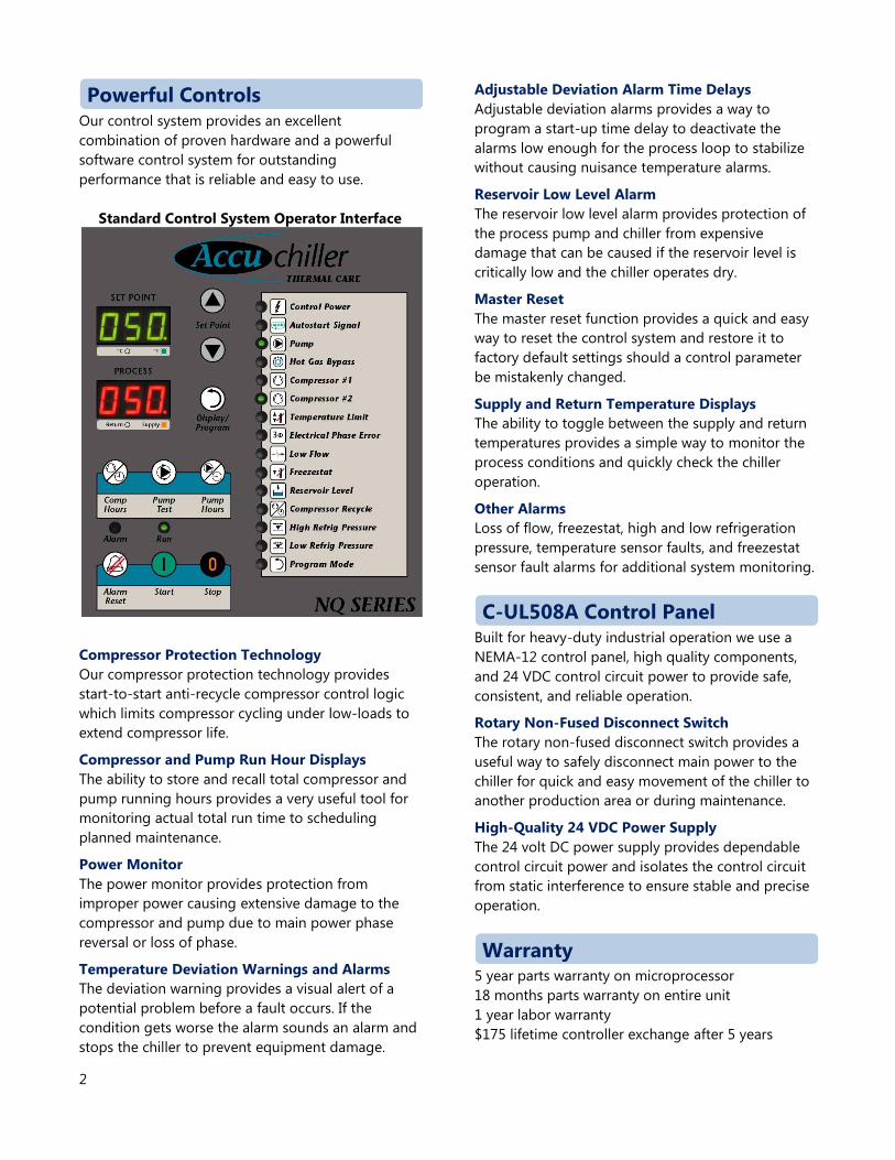
Our control system provides an excellent
combination of proven hardware and a powerful
software control system for outstanding
performance that is reliable and easy to use.
Standard Control System Operator Interface
Compressor Protection Technology
Our compressor protection technology provides
start-to-start anti-recycle compressor control logic
which limits compressor cycling under low-loads to
extend compressor life.
Compressor and Pump Run Hour Displays
The ability to store and recall total compressor and
pump running hours provides a very useful tool for
monitoring actual total run time to scheduling
planned maintenance.
Power Monitor
The power monitor provides protection from
improper power causing extensive damage to the
compressor and pump due to main power phase
reversal or loss of phase.
Temperature Deviation Warnings and Alarms
The deviation warning provides a visual alert of a
potential problem before a fault occurs. If the
condition gets worse the alarm sounds an alarm and
stops the chiller to prevent equipment damage.
Adjustable Deviation Alarm Time Delays
Adjustable deviation alarms provides a way to
program a start-up time delay to deactivate the
alarms low enough for the process loop to stabilize
without causing nuisance temperature alarms.
Reservoir Low Level Alarm
The reservoir low level alarm provides protection of
the process pump and chiller from expensive
damage that can be caused if the reservoir level is
critically low and the chiller operates dry.
Master Reset
The master reset function provides a quick and easy
way to reset the control system and restore it to
factory default settings should a control parameter
be mistakenly changed.
Supply and Return Temperature Displays
The ability to toggle between the supply and return
temperatures provides a simple way to monitor the
process conditions and quickly check the chiller
operation.
Other Alarms
Loss of flow, freezestat, high and low refrigeration
pressure, temperature sensor faults, and freezestat
sensor fault alarms for additional system monitoring.
Built for heavy-duty industrial operation we use a
NEMA-12 control panel, high quality components,
and 24 VDC control circuit power to provide safe,
consistent, and reliable operation.
Rotary Non-Fused Disconnect Switch
The rotary non-fused disconnect switch provides a
useful way to safely disconnect main power to the
chiller for quick and easy movement of the chiller to
another production area or during maintenance.
High-Quality 24 VDC Power Supply
The 24 volt DC power supply provides dependable
control circuit power and isolates the control circuit
from static interference to ensure stable and precise
operation.
5 year parts warranty on microprocessor
18 months parts warranty on entire unit
1 year labor warranty
$175 lifetime controller exchange after 5 years
Powerful Controls
C-UL508A Control Panel
Warranty
3
Available Options In most situations our standard chiller configuration
is sufficient; however, there are applications where
there is a need for additional features. For those
applications we have a number of available options
to enhance the flexibility of our NQ Series chillers.
Oversized Pumps For applications where the process requires high
process fluid flows or pressures a number of larger
pumps are offered. In most cases this allows for
three or more different pump options for each
model of chiller.
High Flow Unit Design For applications where the process requires higher
process fluid flows and the increased internal
pressure loss is a concern, an oversized evaporator is
offered to reduce the internal fluid circuit pressure
loss.
Low Temperature Air Operation For applications where an indoor-duty chiller with an
integral air-cooled condenser will use condenser air
cooler than 60°F, a low temperature condenser air
operation option is available to provide a head
pressure control valve and receiver to allow the
chiller to operate properly with 0°F to 110°F
incoming condenser air.
Outdoor Duty Design For applications where a chiller with an integral air-
cooled condenser is installed outdoors an outdoor
duty design is a available to provide a head pressure
control valve, receiver, panel heater, weatherproof
controller access window, and other various
weatherproofing items needed to allow the chiller to
operate in environments between -20°F and 110°F.
Remote Condenser Coil Coating For applications where a chiller with an outdoor
remote air-cooled condenser is installed within 5
miles of a salt water coast or areas where the air coil
may be exposed to salt vapor a remote condenser
coil coating is available to provide a rugged,
abrasion resistant coating with very high tensile
strength and flexibility to cover the aluminum fins,
copper tubes, and end plates.
Pump and Tank Deduct For applications where an external pumping system
is provided a pump and tank deduct is available to
eliminate the internal coolant reservoir, coolant
pump, coolant pump starter, and coolant reservoir
low level alarm safety. It is also possible to order the
chiller with the pump only and no reservoir for
applications where no internal reservoir is required
but the pump is required.
Fully Divided Air Section For applications where a 15-ton or larger chiller with
an integral air-cooled condenser is used and there is
need to allow the cabinet doors to be opened while
the chiller is running a fully divide air section is
available to provide an internal divider to separate
the upper condenser air section from the lower
mechanical portion of the chiller.
Stainless Steel Cabinet This option is available for applications where there
is a need for a stainless steel cabinet construction
such as the food industry. A stainless steel cabinet is
available to provide 304 stainless steel exterior
cabinet doors, exterior cabinet frame, and control
panel. The internal mechanical base and supports
remain galvanized steel.
Automatic Electric Water Make-Up For units with an integral reservoir where there is
likely to be a regular loss of process fluid an
automatic electric water make-up is available to
provide a low-level sensor, high-level sensor, and an
electric make-up water solenoid valve to allow for
automatic replenishing of the chiller reservoir from
an external source.
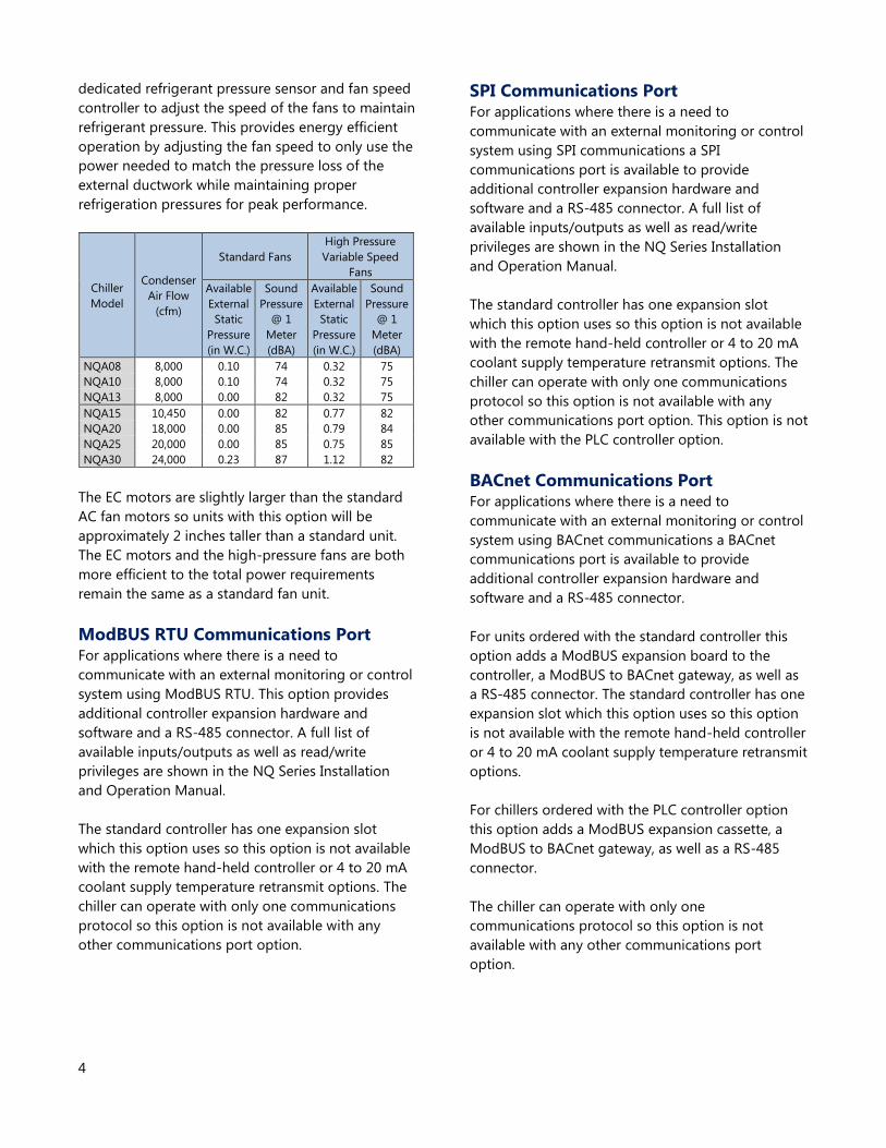
High Pressure Variable Speed Fans For chillers with integral air-cooled condensers
where there is a need to duct the warm discharge air
out of the space where the chiller is located, high
pressure variable-speed fans with EC motors are
available to provide extra fan pressure required for
discharge ductwork. This option is available on the
NQA08 through NQA30 chillers.
With this option the standard constant-speed AC
motor fan(s) are replaced with variable-speed
Electrically Commutated (EC) fan motors and a
4
dedicated refrigerant pressure sensor and fan speed
controller to adjust the speed of the fans to maintain
refrigerant pressure. This provides energy efficient
operation by adjusting the fan speed to only use the
power needed to match the pressure loss of the
external ductwork while maintaining proper
refrigeration pressures for peak performance.
Chiller
Model
Condenser
Air Flow
(cfm)
Standard Fans
High Pressure
Variable Speed
Fans
Available
External
Static
Pressure
(in W.C.)
Sound
Pressure
@ 1
Meter
(dBA)
Available
External
Static
Pressure
(in W.C.)
Sound
Pressure
@ 1
Meter
(dBA)
NQA08 8,000 0.10 74 0.32 75
NQA10 8,000 0.10 74 0.32 75
NQA13 8,000 0.00 82 0.32 75
NQA15 10,450 0.00 82 0.77 82
NQA20 18,000 0.00 85 0.79 84
NQA25 20,000 0.00 85 0.75 85
NQA30 24,000 0.23 87 1.12 82
The EC motors are slightly larger than the standard
AC fan motors so units with this option will be
approximately 2 inches taller than a standard unit.
The EC motors and the high-pressure fans are both
more efficient to the total power requirements
remain the same as a standard fan unit.
ModBUS RTU Communications Port For applications where there is a need to
communicate with an external monitoring or control
system using ModBUS RTU. This option provides
additional controller expansion hardware and
software and a RS-485 connector. A full list of
available inputs/outputs as well as read/write
privileges are shown in the NQ Series Installation
and Operation Manual.
The standard controller has one expansion slot
which this option uses so this option is not available
with the remote hand-held controller or 4 to 20 mA
coolant supply temperature retransmit options. The
chiller can operate with only one communications
protocol so this option is not available with any
other communications port option.
SPI Communications Port For applications where there is a need to
communicate with an external monitoring or control
system using SPI communications a SPI
communications port is available to provide
additional controller expansion hardware and
software and a RS-485 connector. A full list of
available inputs/outputs as well as read/write
privileges are shown in the NQ Series Installation
and Operation Manual.
The standard controller has one expansion slot
which this option uses so this option is not available
with the remote hand-held controller or 4 to 20 mA
coolant supply temperature retransmit options. The
chiller can operate with only one communications
protocol so this option is not available with any
other communications port option. This option is not
available with the PLC controller option.
BACnet Communications Port For applications where there is a need to
communicate with an external monitoring or control
system using BACnet communications a BACnet
communications port is available to provide
additional controller expansion hardware and
software and a RS-485 connector.
For units ordered with the standard controller this
option adds a ModBUS expansion board to the
controller, a ModBUS to BACnet gateway, as well as
a RS-485 connector. The standard controller has one
expansion slot which this option uses so this option
is not available with the remote hand-held controller
or 4 to 20 mA coolant supply temperature retransmit
options.
For chillers ordered with the PLC controller option
this option adds a ModBUS expansion cassette, a
ModBUS to BACnet gateway, as well as a RS-485
connector.
The chiller can operate with only one
communications protocol so this option is not
available with any other communications port
option.
5
LonWorks Communications Port For applications where there is a need to
communicate with an external monitoring or control
system using LonWorks communications a
LonWorks communications port is available to
provide additional controller expansion hardware
and software and a RS-485 connector.
For units ordered with the standard controller this
option adds a ModBUS expansion board to the
controller, a ModBUS to LonWorks gateway, as well
as a RS-485 connector. The standard controller has
one expansion slot which this option uses so this
option is not available with the remote hand-held
controller or 4 to 20 mA coolant supply temperature
retransmit options.
For chillers ordered with the PLC controller option
this option adds a ModBUS expansion cassette, a
ModBUS to BACnet gateway, as well as a RS-485
connector.
The chiller can operate with only one
communications protocol so this option is not
available with any other communications port
option.
Coolant Supply Temperature Retransmit For applications where the is a need for a 4 to 20 mA
output of the coolant temperature leaving the chiller
a 4 to 20 mA coolant supply temperature retransmit
is available to provide a 4 to 20 mA output signal of
the coolant supply temperature.
For units ordered with the standard controller this
option adds an analog output expansion board.
There is one expansion port on the standard control
board so this option is not available with the remote
hand-held controller or communication port options.
For units ordered with the PLC controller option this
option provides an output on one of the PLC analog
output cassettes.
E-Stop Button For applications where there is a need for an
emergency stop button an E-stop button is available
to provide a mushroom-type red emergency stop
button on the front of the chiller. This button
functions in the same way as pushing the stop
button and provides a quick and easy way to stop
the chiller and requires a manual reset to be able to
restart the chiller again.
Hand-Held Controller For applications where there is a need for a remote
hand-held controller in addition to the machine-
mounted controller a hand-held controller is
available for units with the standard controller to
provide an expansion card, remote hand-held
controller, and 50 foot cable. The interconnecting
cable may be extended up to 300 feet. This option is
not available with the PLC controller option.
Special Color Paint For applications where there is a need to match the
color of the chiller cabinet to a specific color special
color paint this option is available to provide a
special color painting of the exterior of the control
panel and cabinetry panels with an air-dry, wet-coat
enamel paint finish. This is for a single-color paint
scheme. For applications where multiple colors are
required on the chiller contact the factory for
assistance.
5 Year Compressor Parts Warranty This option extends the standard 12 month
compressor parts warranty to 60 months for those
applications where there is a need for an added level
of compressor parts warranty coverage.
6
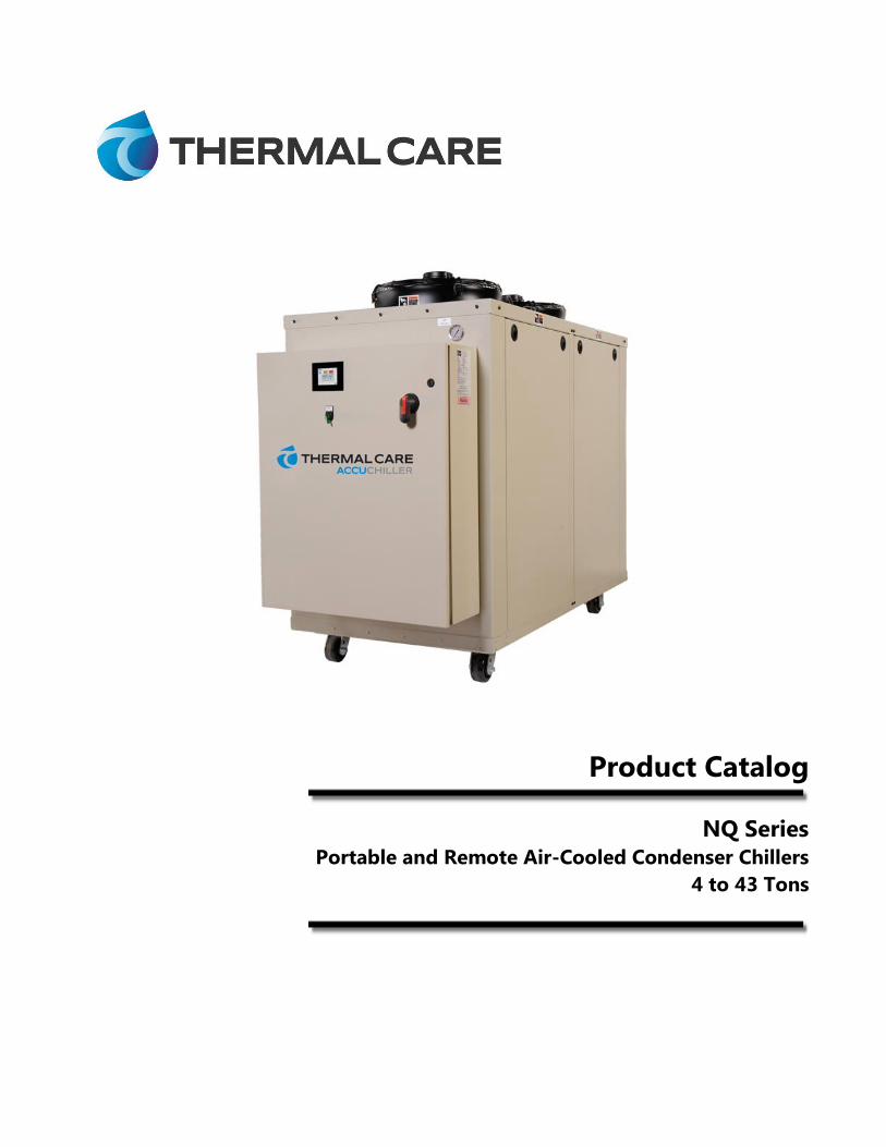
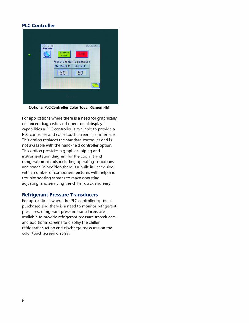
PLC Controller
For applications where there is a need for graphically
enhanced diagnostic and operational display
capabilities a PLC controller is available to provide a
PLC controller and color touch screen user interface.
This option replaces the standard controller and is
not available with the hand-held controller option.
This option provides a graphical piping and
instrumentation diagram for the coolant and
refrigeration circuits including operating conditions
and states. In addition there is a built-in user guide
with a number of component pictures with help and
troubleshooting screens to make operating,
adjusting, and servicing the chiller quick and easy.
Refrigerant Pressure Transducers For applications where the PLC controller option is
purchased and there is a need to monitor refrigerant
pressures, refrigerant pressure transducers are
available to provide refrigerant pressure transducers
and additional screens to display the chiller
refrigerant suction and discharge pressures on the
color touch screen display.
Optional PLC Controller Color Touch-Screen HMI
7
General Data
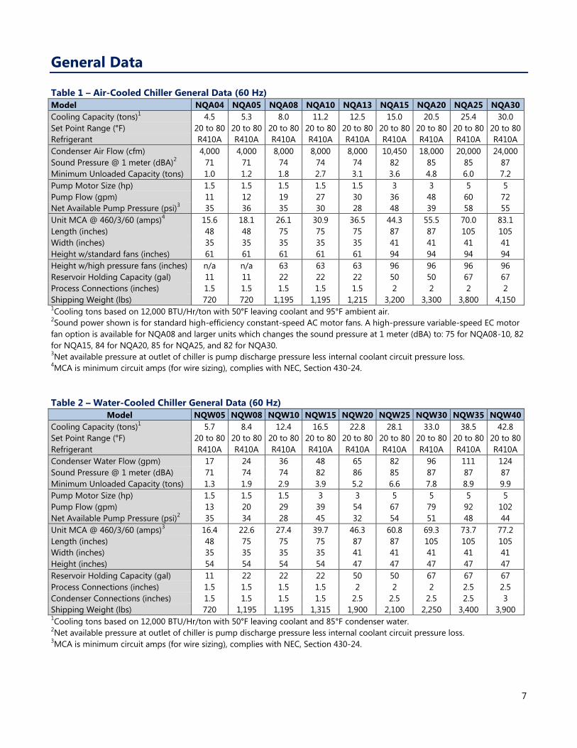
Table 1 – Air-Cooled Chiller General Data (60 Hz)
Model NQA04 NQA05 NQA08 NQA10 NQA13 NQA15 NQA20
NQA25
NQA30
Cooling Capacity (tons)1
4.5 5.3 8.0 11.2 12.5 15.0 20.5 25.4 30.0
Set Point Range (°F) 20 to 80 20 to 80 20 to 80 20 to 80 20 to 80 20 to 80 20 to 80 20 to 80 20 to 80
Refrigerant R410A R410A R410A R410A R410A R410A R410A R410A R410A
Condenser Air Flow (cfm) 4,000 4,000 8,000 8,000 8,000 10,450 18,000 20,000 24,000
Sound Pressure @ 1 meter (dBA)2
71 71 74 74 74 82 85 85 87
Minimum Unloaded Capacity (tons) 1.0 1.2 1.8 2.7 3.1 3.6 4.8 6.0 7.2
Pump Motor Size (hp) 1.5 1.5 1.5 1.5 1.5 3 3 5 5
Pump Flow (gpm) 11 12 19 27 30 36 48 60 72
Net Available Pump Pressure (psi)3
35 36 35 30 28 48 39 58 55
Unit MCA @ 460/3/60 (amps)4
15.6 18.1 26.1 30.9 36.5 44.3 55.5 70.0 83.1
Length (inches) 48 48 75 75 75 87 87 105 105
Width (inches) 35 35 35 35 35 41 41 41 41
Height w/standard fans (inches) 61 61 61 61 61 94 94 94 94
Height w/high pressure fans (inches) n/a n/a 63 63 63 96 96 96 96
Reservoir Holding Capacity (gal) 11 11 22 22 22 50 50 67 67
Process Connections (inches) 1.5 1.5 1.5 1.5 1.5 2 2 2 2
Shipping Weight (lbs) 720 720 1,195 1,195 1,215 3,200 3,300 3,800 4,150 1Cooling tons based on 12,000 BTU/Hr/ton with 50°F leaving coolant and 95°F ambient air.
2Sound power shown is for standard high-efficiency constant-speed AC motor fans. A high-pressure variable-speed EC motor
fan option is available for NQA08 and larger units which changes the sound pressure at 1 meter (dBA) to: 75 for NQA08-10, 82
for NQA15, 84 for NQA20, 85 for NQA25, and 82 for NQA30. 3Net available pressure at outlet of chiller is pump discharge pressure less internal coolant circuit pressure loss.
4MCA is minimum circuit amps (for wire sizing), complies with NEC, Section 430-24.
Table 2 – Water-Cooled Chiller General Data (60 Hz)
Model NQW05 NQW08 NQW10 NQW15 NQW20
NQW25
NQW30
NQW35
NQW40
Cooling Capacity (tons)1
5.7 8.4 12.4 16.5 22.8 28.1 33.0 38.5 42.8
Set Point Range (°F) 20 to 80 20 to 80 20 to 80 20 to 80 20 to 80 20 to 80 20 to 80 20 to 80 20 to 80
Refrigerant R410A R410A R410A R410A R410A R410A R410A R410A R410A
Condenser Water Flow (gpm) 17 24 36 48 65 82 96 111 124
Sound Pressure @ 1 meter (dBA)
71 74 74 82 86 85 87 87 87
Minimum Unloaded Capacity (tons) 1.3 1.9 2.9 3.9 5.2 6.6 7.8 8.9 9.9
Pump Motor Size (hp) 1.5 1.5 1.5 3 3 5 5 5 5
Pump Flow (gpm) 13 20 29 39 54 67 79 92 102
Net Available Pump Pressure (psi)2
35 34 28 45 32 54 51 48 44
Unit MCA @ 460/3/60 (amps)3
16.4 22.6 27.4 39.7 46.3 60.8 69.3 73.7 77.2
Length (inches) 48 75 75 75 87 87 105 105 105
Width (inches) 35 35 35 35 41 41 41 41 41
Height (inches) 54 54 54 54 47 47 47 47 47
Reservoir Holding Capacity (gal) 11 22 22 22 50 50 67 67 67
Process Connections (inches) 1.5 1.5 1.5 1.5 2 2 2 2.5 2.5
Condenser Connections (inches) 1.5 1.5 1.5 1.5 2.5 2.5 2.5 2.5 3
Shipping Weight (lbs) 720 1,195 1,195 1,315 1,900 2,100 2,250 3,400 3,900 1Cooling tons based on 12,000 BTU/Hr/ton with 50°F leaving coolant and 85°F condenser water.
2Net available pressure at outlet of chiller is pump discharge pressure less internal coolant circuit pressure loss.
3MCA is minimum circuit amps (for wire sizing), complies with NEC, Section 430-24.
8
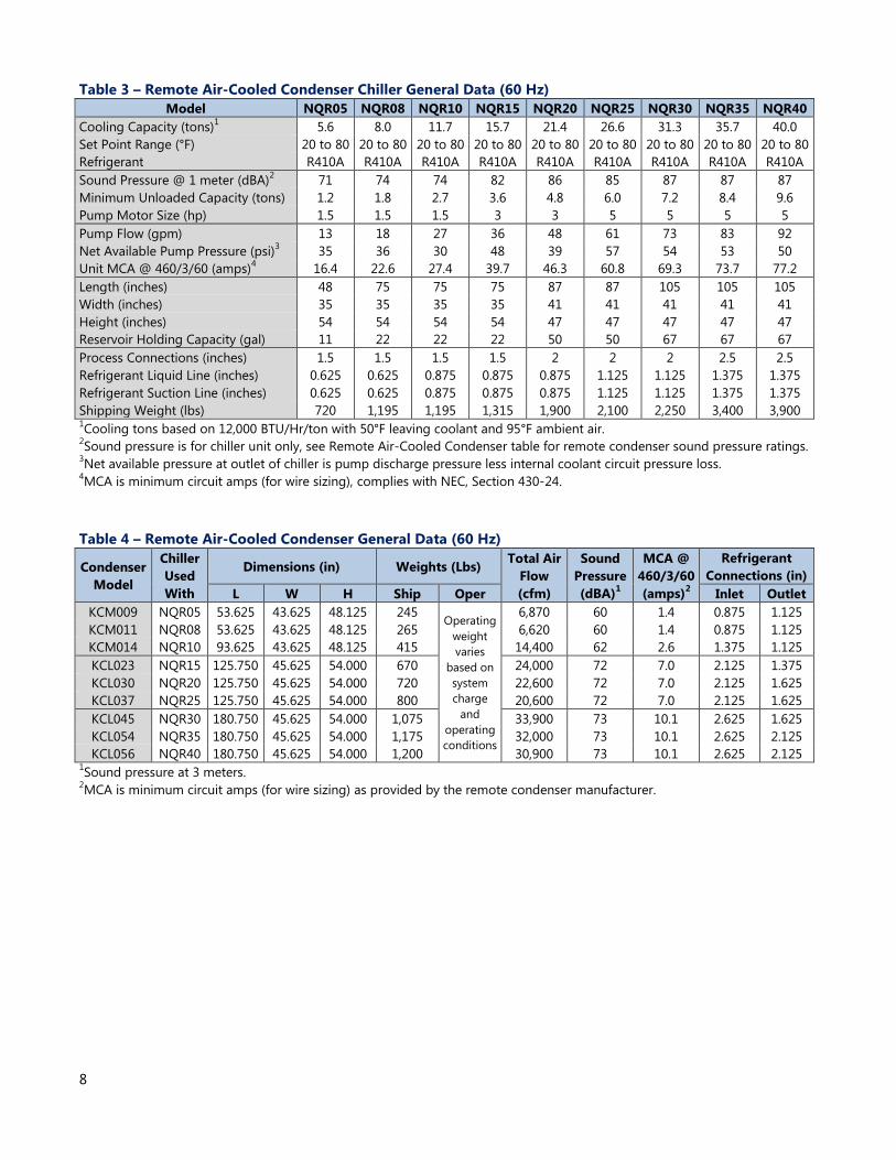
Table 3 – Remote Air-Cooled Condenser Chiller General Data (60 Hz)
Model NQR05 NQR08 NQR10 NQR15 NQR20
NQR25
NQR30
NQR35
NQR40
Cooling Capacity (tons)1
5.6 8.0 11.7 15.7 21.4 26.6 31.3 35.7 40.0
Set Point Range (°F) 20 to 80 20 to 80 20 to 80 20 to 80 20 to 80 20 to 80 20 to 80 20 to 80 20 to 80
Refrigerant R410A R410A R410A R410A R410A R410A R410A R410A R410A
Sound Pressure @ 1 meter (dBA)2
71 74 74 82 86 85 87 87 87
Minimum Unloaded Capacity (tons) 1.2 1.8 2.7 3.6 4.8 6.0 7.2 8.4 9.6
Pump Motor Size (hp) 1.5 1.5 1.5 3 3 5 5 5 5
Pump Flow (gpm) 13 18 27 36 48 61 73 83 92
Net Available Pump Pressure (psi)3
35 36 30 48 39 57 54 53 50
Unit MCA @ 460/3/60 (amps)4
16.4 22.6 27.4 39.7 46.3 60.8 69.3 73.7 77.2
Length (inches) 48 75 75 75 87 87 105 105 105
Width (inches) 35 35 35 35 41 41 41 41 41
Height (inches) 54 54 54 54 47 47 47 47 47
Reservoir Holding Capacity (gal) 11 22 22 22 50 50 67 67 67
Process Connections (inches) 1.5 1.5 1.5 1.5 2 2 2 2.5 2.5
Refrigerant Liquid Line (inches) 0.625 0.625 0.875 0.875 0.875 1.125 1.125 1.375 1.375
Refrigerant Suction Line (inches) 0.625 0.625 0.875 0.875 0.875 1.125 1.125 1.375 1.375
Shipping Weight (lbs) 720 1,195 1,195 1,315 1,900 2,100 2,250 3,400 3,900 1Cooling tons based on 12,000 BTU/Hr/ton with 50°F leaving coolant and 95°F ambient air.
2Sound pressure is for chiller unit only, see Remote Air-Cooled Condenser table for remote condenser sound pressure ratings.
3Net available pressure at outlet of chiller is pump discharge pressure less internal coolant circuit pressure loss.
4MCA is minimum circuit amps (for wire sizing), complies with NEC, Section 430-24.
Table 4 – Remote Air-Cooled Condenser General Data (60 Hz)
Condenser
Model
Chiller
Used
With
Dimensions (in) Weights (Lbs) Total Air
Flow
(cfm)
Sound
Pressure
(dBA)1
MCA @
460/3/60
(amps)2
Refrigerant
Connections (in)
L W H Ship Oper Inlet Outlet
KCM009 NQR05 53.625 43.625 48.125 245 Operating
weight
varies
based on
system
charge
and
operating
conditions
6,870 60 1.4 0.875 1.125
KCM011 NQR08 53.625 43.625 48.125 265 6,620 60 1.4 0.875 1.125
KCM014 NQR10 93.625 43.625 48.125 415 14,400 62 2.6 1.375 1.125
KCL023 NQR15 125.750 45.625 54.000 670 24,000 72 7.0 2.125 1.375
KCL030 NQR20 125.750 45.625 54.000 720 22,600 72 7.0 2.125 1.625
KCL037 NQR25 125.750 45.625 54.000 800 20,600 72 7.0 2.125 1.625
KCL045 NQR30 180.750 45.625 54.000 1,075 33,900 73 10.1 2.625 1.625
KCL054 NQR35 180.750 45.625 54.000 1,175 32,000 73 10.1 2.625 2.125
KCL056 NQR40 180.750 45.625 54.000 1,200 30,900 73 10.1 2.625 2.125 1Sound pressure at 3 meters.
2MCA is minimum circuit amps (for wire sizing) as provided by the remote condenser manufacturer.
9
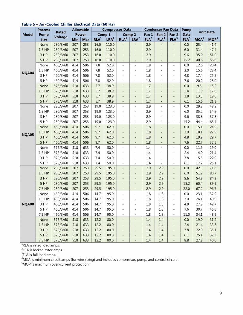
Table 5 – Air-Cooled Chiller Electrical Data (60 Hz)
Model
Process
Pump
Size
Rated
Voltage
Allowable
Power
Compressor Data Condenser Fan Data Pump
Data Unit Data
Comp 1 Comp 2 Fan 1 Fan 2 Fan 2
Min Max RLA1 LRA
2 RLA
1 LRA
2 FLA
3 FLA
3 FLA
3 FLA
3 MCA
4 MOP
5
NQA04
None 230/3/60 207 253 16.0 110.0 - - 2.9 - - 0.0 25.4 41.4
1.5 HP 230/3/60 207 253 16.0 110.0 - - 2.9 - - 6.0 31.4 47.4
3 HP 230/3/60 207 253 16.0 110.0 - - 2.9 - - 9.6 35.0 51.0
5 HP 230/3/60 207 253 16.0 110.0 - - 2.9 - - 15.2 40.6 56.6
None 460/3/60 414 506 7.8 52.0 - - 1.8 - - 0.0 12.6 20.4
1.5 HP 460/3/60 414 506 7.8 52.0 - - 1.8 - - 3.0 15.6 23.4
3 HP 460/3/60 414 506 7.8 52.0 - - 1.8 - - 4.8 17.4 25.2
5 HP 460/3/60 414 506 7.8 52.0 - - 1.8 - - 7.6 20.2 28.0
None 575/3/60 518 633 5.7 38.9 - - 1.7 - - 0.0 9.5 15.2
1.5 HP 575/3/60 518 633 5.7 38.9 - - 1.7 - - 2.4 11.9 17.6
3 HP 575/3/60 518 633 5.7 38.9 - - 1.7 - - 3.8 13.3 19.0
5 HP 575/3/60 518 633 5.7 38.9 - - 1.7 - - 6.1 15.6 21.3
NQA05
None 230/3/60 207 253 19.0 123.0 - - 2.9 - - 0.0 29.2 48.2
1.5 HP 230/3/60 207 253 19.0 123.0 - - 2.9 - - 6.0 35.2 54.2
3 HP 230/3/60 207 253 19.0 123.0 - - 2.9 - - 9.6 38.8 57.8
5 HP 230/3/60 207 253 19.0 123.0 - - 2.9 - - 15.2 44.4 63.4
None 460/3/60 414 506 9.7 62.0 - - 1.8 - - 0.0 15.1 24.9
1.5 HP 460/3/60 414 506 9.7 62.0 - - 1.8 - - 3.0 18.1 27.9
3 HP 460/3/60 414 506 9.7 62.0 - - 1.8 - - 4.8 19.9 29.7
5 HP 460/3/60 414 506 9.7 62.0 - - 1.8 - - 7.6 22.7 32.5
None 575/3/60 518 633 7.4 50.0 - - 1.4 - - 0.0 11.6 19.0
1.5 HP 575/3/60 518 633 7.4 50.0 - - 1.4 - - 2.4 14.0 21.4
3 HP 575/3/60 518 633 7.4 50.0 - - 1.4 - - 3.8 15.5 22.9
5 HP 575/3/60 518 633 7.4 50.0 - - 1.4 - - 6.1 17.7 25.1
NQA08
None 230/3/60 207 253 29.5 195.0 - - 2.9 2.9 - 0.0 42.3 71.8
1.5 HP 230/3/60 207 253 29.5 195.0 - - 2.9 2.9 - 6.0 51.2 80.7
3 HP 230/3/60 207 253 29.5 195.0 - - 2.9 2.9 - 9.6 54.8 84.3
5 HP 230/3/60 207 253 29.5 195.0 - - 2.9 2.9 - 15.2 60.4 89.9
7.5 HP 230/3/60 207 253 29.5 195.0 - - 2.9 2.9 - 22.0 67.2 96.7
None 460/3/60 414 506 14.7 95.0 - - 1.8 1.8 - 0.0 23.1 37.9
1.5 HP 460/3/60 414 506 14.7 95.0 - - 1.8 1.8 - 3.0 26.1 40.9
3 HP 460/3/60 414 506 14.7 95.0 - - 1.8 1.8 - 4.8 27.9 42.7
5 HP 460/3/60 414 506 14.7 95.0 - - 1.8 1.8 - 7.6 30.7 45.5
7.5 HP 460/3/60 414 506 14.7 95.0 - - 1.8 1.8 - 11.0 34.1 48.9
None 575/3/60 518 633 12.2 80.0 - - 1.4 1.4 - 0.0 19.0 31.2
1.5 HP 575/3/60 518 633 12.2 80.0 - - 1.4 1.4 - 2.4 21.4 33.6
3 HP 575/3/60 518 633 12.2 80.0 - - 1.4 1.4 - 3.8 22.9 35.1
5 HP 575/3/60 518 633 12.2 80.0 - - 1.4 1.4 - 6.1 25.1 37.3
7.5 HP 575/3/60 518 633 12.2 80.0 - - 1.4 1.4 - 8.8 27.8 40.0 1RLA is rated load amps.
2LRA is locked rotor amps.
3FLA is full load amps.
4MCA is minimum circuit amps (for wire sizing) and includes compressor, pump, and control circuit.
5MOP is maximum over-current protection.
10
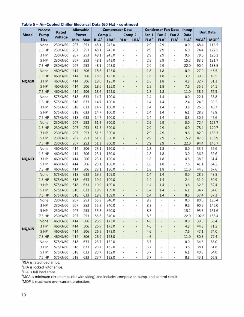
Table 5 – Air-Cooled Chiller Electrical Data (60 Hz) - continued
Model
Process
Pump
Size
Rated
Voltage
Allowable
Power
Compressor Data Condenser Fan Data Pump
Data Unit Data
Comp 1 Comp 2 Fan 1 Fan 2 Fan 2
Min Max RLA1 LRA
2 RLA
1 LRA
2 FLA
3 FLA
3 FLA
3 FLA
3 MCA
4 MOP
5
NQA10
None 230/3/60 207 253 48.1 245.0 - - 2.9 2.9 - 0.0 68.4 116.5
1.5 HP 230/3/60 207 253 48.1 245.0 - - 2.9 2.9 - 6.0 74.4 122.5
3 HP 230/3/60 207 253 48.1 245.0 - - 2.9 2.9 - 9.6 78.0 126.1
5 HP 230/3/60 207 253 48.1 245.0 - - 2.9 2.9 - 15.2 83.6 131.7
7.5 HP 230/3/60 207 253 48.1 245.0 - - 2.9 2.9 - 22.0 90.4 138.5
None 460/3/60 414 506 18.6 125.0 - - 1.8 1.8 - 0.0 27.9 46.5
1.5 HP 460/3/60 414 506 18.6 125.0 - - 1.8 1.8 - 3.0 30.9 49.5
3 HP 460/3/60 414 506 18.6 125.0 - - 1.8 1.8 - 4.8 32.7 51.3
5 HP 460/3/60 414 506 18.6 125.0 - - 1.8 1.8 - 7.6 35.5 54.1
7.5 HP 460/3/60 414 506 18.6 125.0 - - 1.8 1.8 - 11.0 38.9 57.5
None 575/3/60 518 633 14.7 100.0 - - 1.4 1.4 - 0.0 22.1 36.8
1.5 HP 575/3/60 518 633 14.7 100.0 - - 1.4 1.4 - 2.4 24.5 39.2
3 HP 575/3/60 518 633 14.7 100.0 - - 1.4 1.4 - 3.8 26.0 40.7
5 HP 575/3/60 518 633 14.7 100.0 - - 1.4 1.4 - 6.1 28.2 42.9
7.5 HP 575/3/60 518 633 14.7 100.0 - - 1.4 1.4 - 8.8 30.9 45.6
NQA13
None 230/3/60 207 253 51.3 300.0 - - 2.9 2.9 - 0.0 72.4 123.7
1.5 HP 230/3/60 207 253 51.3 300.0 - - 2.9 2.9 - 6.0 78.4 129.7
3 HP 230/3/60 207 253 51.3 300.0 - - 2.9 2.9 - 9.6 82.0 133.3
5 HP 230/3/60 207 253 51.3 300.0 - - 2.9 2.9 - 15.2 87.6 138.9
7.5 HP 230/3/60 207 253 51.3 300.0 - - 2.9 2.9 - 22.0 94.4 145.7
None 460/3/60 414 506 23.1 150.0 - - 1.8 1.8 - 0.0 33.5 56.6
1.5 HP 460/3/60 414 506 23.1 150.0 - - 1.8 1.8 - 3.0 36.5 59.6
3 HP 460/3/60 414 506 23.1 150.0 - - 1.8 1.8 - 4.8 38.3 61.4
5 HP 460/3/60 414 506 23.1 150.0 - - 1.8 1.8 - 7.6 41.1 64.2
7.5 HP 460/3/60 414 506 23.1 150.0 - - 1.8 1.8 - 11.0 44.5 67.6
None 575/3/60 518 633 19.9 109.0 - - 1.4 1.4 - 0.0 28.6 48.5
1.5 HP 575/3/60 518 633 19.9 109.0 - - 1.4 1.4 - 2.4 31.0 50.9
3 HP 575/3/60 518 633 19.9 109.0 - - 1.4 1.4 - 3.8 32.5 52.4
5 HP 575/3/60 518 633 19.9 109.0 - - 1.4 1.4 - 6.1 34.7 54.6
7.5 HP 575/3/60 518 633 19.9 109.0 - - 1.4 1.4 - 8.8 37.4 57.3
NQA15
None 230/3/60 207 253 55.8 340.0 - - 8.3 - - 0.0 80.6 136.4
3 HP 230/3/60 207 253 55.8 340.0 - - 8.3 - - 9.6 90.2 146.0
5 HP 230/3/60 207 253 55.8 340.0 - - 8.3 - - 15.2 95.8 151.6
7.5 HP 230/3/60 207 253 55.8 340.0 - - 8.3 - - 22.0 102.6 158.4
None 460/3/60 414 506 26.9 173.0 - - 4.6 - - 0.0 39.5 66.4
3 HP 460/3/60 414 506 26.9 173.0 - - 4.6 - - 4.8 44.3 71.2
5 HP 460/3/60 414 506 26.9 173.0 - - 4.6 - - 7.6 47.1 74.0
7.5 HP 460/3/60 414 506 26.9 173.0 - - 4.6 - - 11.0 50.5 77.4
None 575/3/60 518 633 23.7 132.0 - - 3.7 - - 0.0 34.3 58.0
3 HP 575/3/60 518 633 23.7 132.0 - - 3.7 - - 3.8 38.1 61.8
5 HP 575/3/60 518 633 23.7 132.0 - - 3.7 - - 6.1 40.3 64.0
7.5 HP 575/3/60 518 633 23.7 132.0 - - 3.7 - - 8.8 43.1 66.8 1RLA is rated load amps.
2LRA is locked rotor amps.
3FLA is full load amps.
4MCA is minimum circuit amps (for wire sizing) and includes compressor, pump, and control circuit.
5MOP is maximum over-current protection.
11
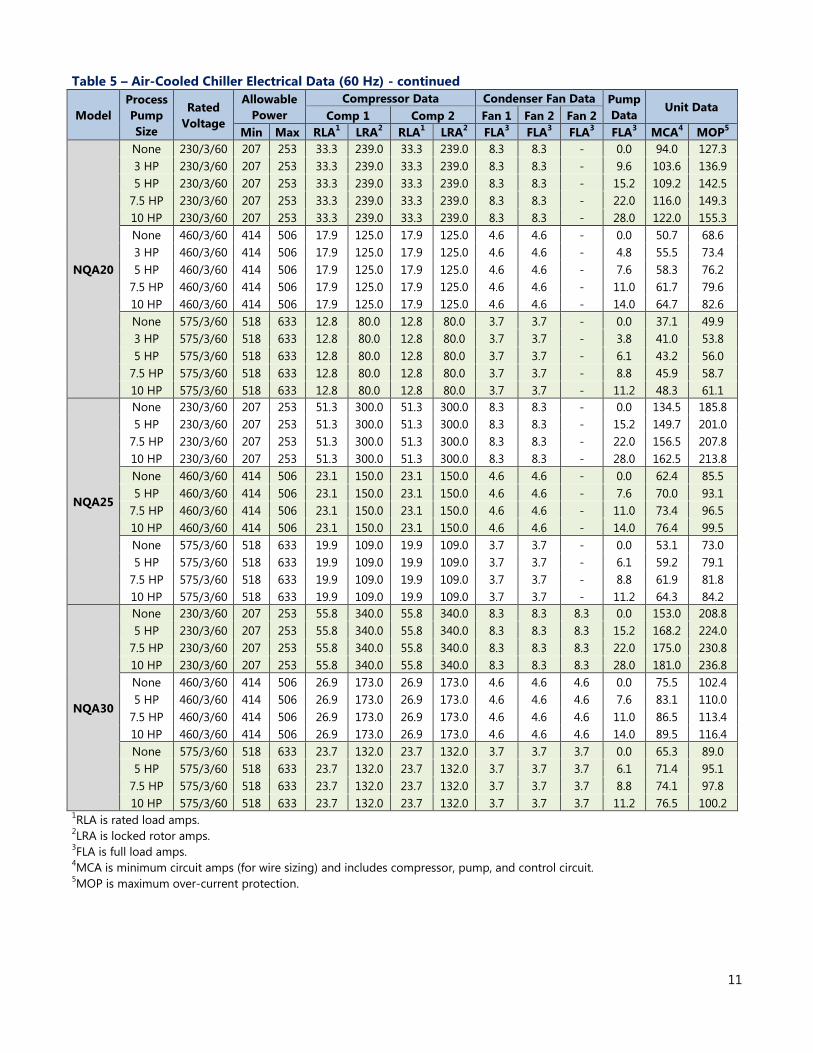
Table 5 – Air-Cooled Chiller Electrical Data (60 Hz) - continued
Model
Process
Pump
Size
Rated
Voltage
Allowable
Power
Compressor Data Condenser Fan Data Pump
Data Unit Data
Comp 1 Comp 2 Fan 1 Fan 2 Fan 2
Min Max RLA1 LRA
2 RLA
1 LRA
2 FLA
3 FLA
3 FLA
3 FLA
3 MCA
4 MOP
5
NQA20
None 230/3/60 207 253 33.3 239.0 33.3 239.0 8.3 8.3 - 0.0 94.0 127.3
3 HP 230/3/60 207 253 33.3 239.0 33.3 239.0 8.3 8.3 - 9.6 103.6 136.9
5 HP 230/3/60 207 253 33.3 239.0 33.3 239.0 8.3 8.3 - 15.2 109.2 142.5
7.5 HP 230/3/60 207 253 33.3 239.0 33.3 239.0 8.3 8.3 - 22.0 116.0 149.3
10 HP 230/3/60 207 253 33.3 239.0 33.3 239.0 8.3 8.3 - 28.0 122.0 155.3
None 460/3/60 414 506 17.9 125.0 17.9 125.0 4.6 4.6 - 0.0 50.7 68.6
3 HP 460/3/60 414 506 17.9 125.0 17.9 125.0 4.6 4.6 - 4.8 55.5 73.4
5 HP 460/3/60 414 506 17.9 125.0 17.9 125.0 4.6 4.6 - 7.6 58.3 76.2
7.5 HP 460/3/60 414 506 17.9 125.0 17.9 125.0 4.6 4.6 - 11.0 61.7 79.6
10 HP 460/3/60 414 506 17.9 125.0 17.9 125.0 4.6 4.6 - 14.0 64.7 82.6
None 575/3/60 518 633 12.8 80.0 12.8 80.0 3.7 3.7 - 0.0 37.1 49.9
3 HP 575/3/60 518 633 12.8 80.0 12.8 80.0 3.7 3.7 - 3.8 41.0 53.8
5 HP 575/3/60 518 633 12.8 80.0 12.8 80.0 3.7 3.7 - 6.1 43.2 56.0
7.5 HP 575/3/60 518 633 12.8 80.0 12.8 80.0 3.7 3.7 - 8.8 45.9 58.7
10 HP 575/3/60 518 633 12.8 80.0 12.8 80.0 3.7 3.7 - 11.2 48.3 61.1
NQA25
None 230/3/60 207 253 51.3 300.0 51.3 300.0 8.3 8.3 - 0.0 134.5 185.8
5 HP 230/3/60 207 253 51.3 300.0 51.3 300.0 8.3 8.3 - 15.2 149.7 201.0
7.5 HP 230/3/60 207 253 51.3 300.0 51.3 300.0 8.3 8.3 - 22.0 156.5 207.8
10 HP 230/3/60 207 253 51.3 300.0 51.3 300.0 8.3 8.3 - 28.0 162.5 213.8
None 460/3/60 414 506 23.1 150.0 23.1 150.0 4.6 4.6 - 0.0 62.4 85.5
5 HP 460/3/60 414 506 23.1 150.0 23.1 150.0 4.6 4.6 - 7.6 70.0 93.1
7.5 HP 460/3/60 414 506 23.1 150.0 23.1 150.0 4.6 4.6 - 11.0 73.4 96.5
10 HP 460/3/60 414 506 23.1 150.0 23.1 150.0 4.6 4.6 - 14.0 76.4 99.5
None 575/3/60 518 633 19.9 109.0 19.9 109.0 3.7 3.7 - 0.0 53.1 73.0
5 HP 575/3/60 518 633 19.9 109.0 19.9 109.0 3.7 3.7 - 6.1 59.2 79.1
7.5 HP 575/3/60 518 633 19.9 109.0 19.9 109.0 3.7 3.7 - 8.8 61.9 81.8
10 HP 575/3/60 518 633 19.9 109.0 19.9 109.0 3.7 3.7 - 11.2 64.3 84.2
NQA30
None 230/3/60 207 253 55.8 340.0 55.8 340.0 8.3 8.3 8.3 0.0 153.0 208.8
5 HP 230/3/60 207 253 55.8 340.0 55.8 340.0 8.3 8.3 8.3 15.2 168.2 224.0
7.5 HP 230/3/60 207 253 55.8 340.0 55.8 340.0 8.3 8.3 8.3 22.0 175.0 230.8
10 HP 230/3/60 207 253 55.8 340.0 55.8 340.0 8.3 8.3 8.3 28.0 181.0 236.8
None 460/3/60 414 506 26.9 173.0 26.9 173.0 4.6 4.6 4.6 0.0 75.5 102.4
5 HP 460/3/60 414 506 26.9 173.0 26.9 173.0 4.6 4.6 4.6 7.6 83.1 110.0
7.5 HP 460/3/60 414 506 26.9 173.0 26.9 173.0 4.6 4.6 4.6 11.0 86.5 113.4
10 HP 460/3/60 414 506 26.9 173.0 26.9 173.0 4.6 4.6 4.6 14.0 89.5 116.4
None 575/3/60 518 633 23.7 132.0 23.7 132.0 3.7 3.7 3.7 0.0 65.3 89.0
5 HP 575/3/60 518 633 23.7 132.0 23.7 132.0 3.7 3.7 3.7 6.1 71.4 95.1
7.5 HP 575/3/60 518 633 23.7 132.0 23.7 132.0 3.7 3.7 3.7 8.8 74.1 97.8
10 HP 575/3/60 518 633 23.7 132.0 23.7 132.0 3.7 3.7 3.7 11.2 76.5 100.2 1RLA is rated load amps.
2LRA is locked rotor amps.
3FLA is full load amps.
4MCA is minimum circuit amps (for wire sizing) and includes compressor, pump, and control circuit.
5MOP is maximum over-current protection.
12
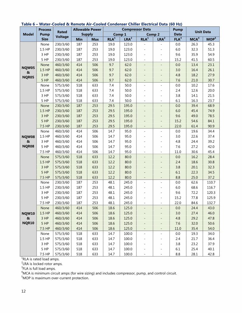
Table 6 – Water-Cooled & Remote Air-Cooled Condenser Chiller Electrical Data (60 Hz)
Model
Process
Pump
Size
Rated
Voltage
Allowable Power
Supply
Compressor Data Pump
Data Unit Data
Comp 1 Comp 2
Min Max RLA1 LRA
2 RLA
1 LRA
2 FLA
3 MCA
4 MOP
5
NQW05
&
NQR05
None 230/3/60 187 253 19.0 123.0 - - 0.0 26.3 45.3
1.5 HP 230/3/60 187 253 19.0 123.0 - - 6.0 32.3 51.3
3 HP 230/3/60 187 253 19.0 123.0 - - 9.6 35.9 54.9
5 HP 230/3/60 187 253 19.0 123.0 - - 15.2 41.5 60.5
None 460/3/60 414 506 9.7 62.0 - - 0.0 13.4 23.1
1.5 HP 460/3/60 414 506 9.7 62.0 - - 3.0 16.4 26.1
3 HP 460/3/60 414 506 9.7 62.0 - - 4.8 18.2 27.9
5 HP 460/3/60 414 506 9.7 62.0 - - 7.6 21.0 30.7
None 575/3/60 518 633 7.4 50.0 - - 0.0 10.2 17.6
1.5 HP 575/3/60 518 633 7.4 50.0 - - 2.4 12.6 20.0
3 HP 575/3/60 518 633 7.4 50.0 - - 3.8 14.1 21.5
5 HP 575/3/60 518 633 7.4 50.0 - - 6.1 16.3 23.7
NQW08
&
NQR08
None 230/3/60 187 253 29.5 195.0 - - 0.0 39.4 68.9
1.5 HP 230/3/60 187 253 29.5 195.0 - - 6.0 45.4 74.9
3 HP 230/3/60 187 253 29.5 195.0 - - 9.6 49.0 78.5
5 HP 230/3/60 187 253 29.5 195.0 - - 15.2 54.6 84.1
7.5 HP 230/3/60 187 253 29.5 195.0 - - 22.0 61.4 90.9
None 460/3/60 414 506 14.7 95.0 - - 0.0 19.6 34.4
1.5 HP 460/3/60 414 506 14.7 95.0 - - 3.0 22.6 37.4
3 HP 460/3/60 414 506 14.7 95.0 - - 4.8 24.4 39.2
5 HP 460/3/60 414 506 14.7 95.0 - - 7.6 27.2 42.0
7.5 HP 460/3/60 414 506 14.7 95.0 - - 11.0 30.6 45.4
None 575/3/60 518 633 12.2 80.0 - - 0.0 16.2 28.4
1.5 HP 575/3/60 518 633 12.2 80.0 - - 2.4 18.6 30.8
3 HP 575/3/60 518 633 12.2 80.0 - - 3.8 20.1 32.3
5 HP 575/3/60 518 633 12.2 80.0 - - 6.1 22.3 34.5
7.5 HP 575/3/60 518 633 12.2 80.0 - - 8.8 25.0 37.2
NQW10
&
NQR10
None 230/3/60 187 253 48.1 245.0 - - 0.0 62.6 110.7
1.5 HP 230/3/60 187 253 48.1 245.0 - - 6.0 68.6 116.7
3 HP 230/3/60 187 253 48.1 245.0 - - 9.6 72.2 120.3
5 HP 230/3/60 187 253 48.1 245.0 - - 15.2 77.8 125.9
7.5 HP 230/3/60 187 253 48.1 245.0 - - 22.0 84.6 132.7
None 460/3/60 414 506 18.6 125.0 - - 0.0 24.4 43.0
1.5 HP 460/3/60 414 506 18.6 125.0 - - 3.0 27.4 46.0
3 HP 460/3/60 414 506 18.6 125.0 - - 4.8 29.2 47.8
5 HP 460/3/60 414 506 18.6 125.0 - - 7.6 32.0 50.6
7.5 HP 460/3/60 414 506 18.6 125.0 - - 11.0 35.4 54.0
None 575/3/60 518 633 14.7 100.0 - - 0.0 19.3 34.0
1.5 HP 575/3/60 518 633 14.7 100.0 - - 2.4 21.7 36.4
3 HP 575/3/60 518 633 14.7 100.0 - - 3.8 23.2 37.9
5 HP 575/3/60 518 633 14.7 100.0 - - 6.1 25.4 40.1
7.5 HP 575/3/60 518 633 14.7 100.0 - - 8.8 28.1 42.8 1RLA is rated load amps.
2LRA is locked rotor amps.
3FLA is full load amps.
4MCA is minimum circuit amps (for wire sizing) and includes compressor, pump, and control circuit.
5MOP is maximum over-current protection.
13
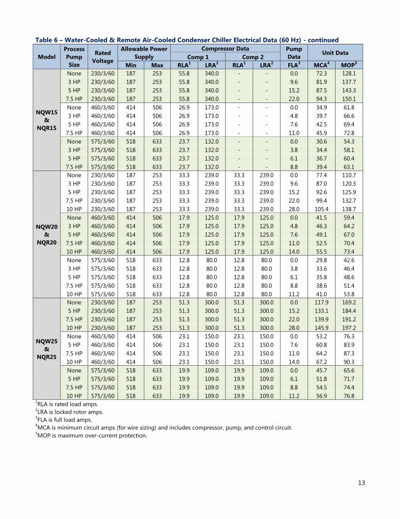
Table 6 – Water-Cooled & Remote Air-Cooled Condenser Chiller Electrical Data (60 Hz) - continued
Model
Process
Pump
Size
Rated
Voltage
Allowable Power
Supply
Compressor Data Pump
Data Unit Data
Comp 1 Comp 2
Min Max RLA1 LRA
2 RLA
1 LRA
2 FLA
3 MCA
4 MOP
5
NQW15
&
NQR15
None 230/3/60 187 253 55.8 340.0 - - 0.0 72.3 128.1
3 HP 230/3/60 187 253 55.8 340.0 - - 9.6 81.9 137.7
5 HP 230/3/60 187 253 55.8 340.0 - - 15.2 87.5 143.3
7.5 HP 230/3/60 187 253 55.8 340.0 - - 22.0 94.3 150.1
None 460/3/60 414 506 26.9 173.0 - - 0.0 34.9 61.8
3 HP 460/3/60 414 506 26.9 173.0 - - 4.8 39.7 66.6
5 HP 460/3/60 414 506 26.9 173.0 - - 7.6 42.5 69.4
7.5 HP 460/3/60 414 506 26.9 173.0 - - 11.0 45.9 72.8
None 575/3/60 518 633 23.7 132.0 - - 0.0 30.6 54.3
3 HP 575/3/60 518 633 23.7 132.0 - - 3.8 34.4 58.1
5 HP 575/3/60 518 633 23.7 132.0 - - 6.1 36.7 60.4
7.5 HP 575/3/60 518 633 23.7 132.0 - - 8.8 39.4 63.1
NQW20
&
NQR20
None 230/3/60 187 253 33.3 239.0 33.3 239.0 0.0 77.4 110.7
3 HP 230/3/60 187 253 33.3 239.0 33.3 239.0 9.6 87.0 120.3
5 HP 230/3/60 187 253 33.3 239.0 33.3 239.0 15.2 92.6 125.9
7.5 HP 230/3/60 187 253 33.3 239.0 33.3 239.0 22.0 99.4 132.7
10 HP 230/3/60 187 253 33.3 239.0 33.3 239.0 28.0 105.4 138.7
None 460/3/60 414 506 17.9 125.0 17.9 125.0 0.0 41.5 59.4
3 HP 460/3/60 414 506 17.9 125.0 17.9 125.0 4.8 46.3 64.2
5 HP 460/3/60 414 506 17.9 125.0 17.9 125.0 7.6 49.1 67.0
7.5 HP 460/3/60 414 506 17.9 125.0 17.9 125.0 11.0 52.5 70.4
10 HP 460/3/60 414 506 17.9 125.0 17.9 125.0 14.0 55.5 73.4
None 575/3/60 518 633 12.8 80.0 12.8 80.0 0.0 29.8 42.6
3 HP 575/3/60 518 633 12.8 80.0 12.8 80.0 3.8 33.6 46.4
5 HP 575/3/60 518 633 12.8 80.0 12.8 80.0 6.1 35.8 48.6
7.5 HP 575/3/60 518 633 12.8 80.0 12.8 80.0 8.8 38.6 51.4
10 HP 575/3/60 518 633 12.8 80.0 12.8 80.0 11.2 41.0 53.8
NQW25
&
NQR25
None 230/3/60 187 253 51.3 300.0 51.3 300.0 0.0 117.9 169.2
5 HP 230/3/60 187 253 51.3 300.0 51.3 300.0 15.2 133.1 184.4
7.5 HP 230/3/60 187 253 51.3 300.0 51.3 300.0 22.0 139.9 191.2
10 HP 230/3/60 187 253 51.3 300.0 51.3 300.0 28.0 145.9 197.2
None 460/3/60 414 506 23.1 150.0 23.1 150.0 0.0 53.2 76.3
5 HP 460/3/60 414 506 23.1 150.0 23.1 150.0 7.6 60.8 83.9
7.5 HP 460/3/60 414 506 23.1 150.0 23.1 150.0 11.0 64.2 87.3
10 HP 460/3/60 414 506 23.1 150.0 23.1 150.0 14.0 67.2 90.3
None 575/3/60 518 633 19.9 109.0 19.9 109.0 0.0 45.7 65.6
5 HP 575/3/60 518 633 19.9 109.0 19.9 109.0 6.1 51.8 71.7
7.5 HP 575/3/60 518 633 19.9 109.0 19.9 109.0 8.8 54.5 74.4
10 HP 575/3/60 518 633 19.9 109.0 19.9 109.0 11.2 56.9 76.8 1RLA is rated load amps.
2LRA is locked rotor amps.
3FLA is full load amps.
4MCA is minimum circuit amps (for wire sizing) and includes compressor, pump, and control circuit.
5MOP is maximum over-current protection.
14
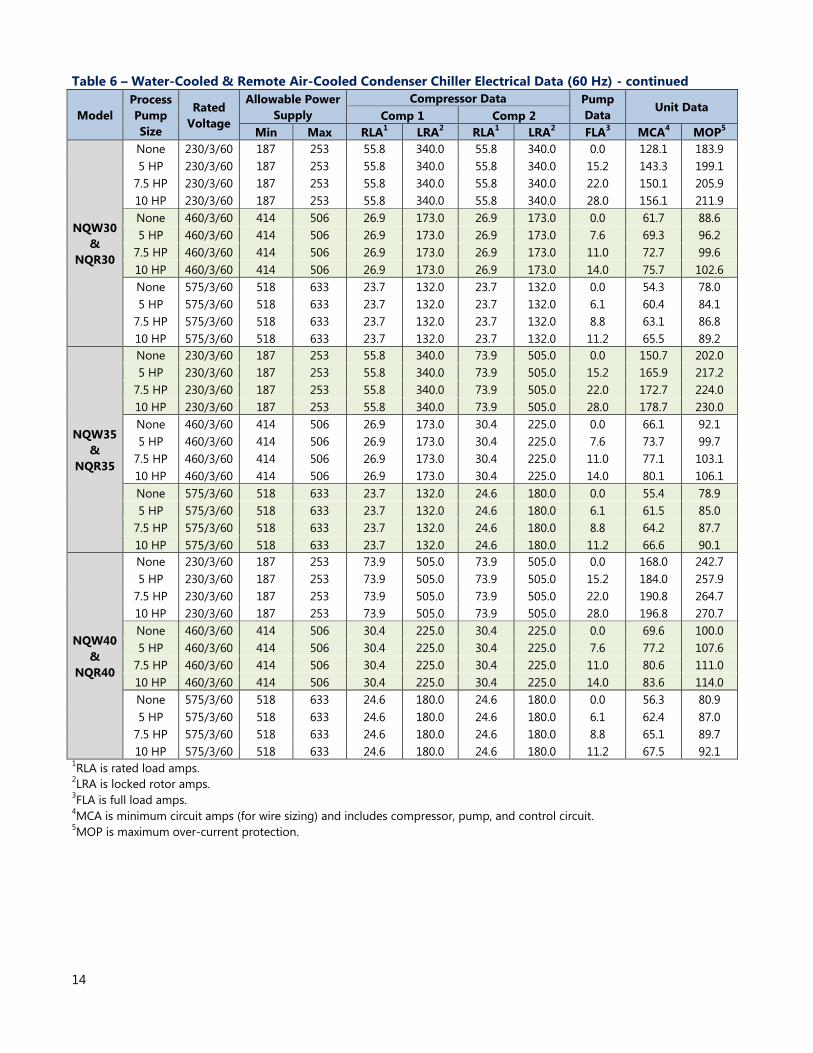
Table 6 – Water-Cooled & Remote Air-Cooled Condenser Chiller Electrical Data (60 Hz) - continued
Model
Process
Pump
Size
Rated
Voltage
Allowable Power
Supply
Compressor Data Pump
Data Unit Data
Comp 1 Comp 2
Min Max RLA1 LRA
2 RLA
1 LRA
2 FLA
3 MCA
4 MOP
5
NQW30
&
NQR30
None 230/3/60 187 253 55.8 340.0 55.8 340.0 0.0 128.1 183.9
5 HP 230/3/60 187 253 55.8 340.0 55.8 340.0 15.2 143.3 199.1
7.5 HP 230/3/60 187 253 55.8 340.0 55.8 340.0 22.0 150.1 205.9
10 HP 230/3/60 187 253 55.8 340.0 55.8 340.0 28.0 156.1 211.9
None 460/3/60 414 506 26.9 173.0 26.9 173.0 0.0 61.7 88.6
5 HP 460/3/60 414 506 26.9 173.0 26.9 173.0 7.6 69.3 96.2
7.5 HP 460/3/60 414 506 26.9 173.0 26.9 173.0 11.0 72.7 99.6
10 HP 460/3/60 414 506 26.9 173.0 26.9 173.0 14.0 75.7 102.6
None 575/3/60 518 633 23.7 132.0 23.7 132.0 0.0 54.3 78.0
5 HP 575/3/60 518 633 23.7 132.0 23.7 132.0 6.1 60.4 84.1
7.5 HP 575/3/60 518 633 23.7 132.0 23.7 132.0 8.8 63.1 86.8
10 HP 575/3/60 518 633 23.7 132.0 23.7 132.0 11.2 65.5 89.2
NQW35
&
NQR35
None 230/3/60 187 253 55.8 340.0 73.9 505.0 0.0 150.7 202.0
5 HP 230/3/60 187 253 55.8 340.0 73.9 505.0 15.2 165.9 217.2
7.5 HP 230/3/60 187 253 55.8 340.0 73.9 505.0 22.0 172.7 224.0
10 HP 230/3/60 187 253 55.8 340.0 73.9 505.0 28.0 178.7 230.0
None 460/3/60 414 506 26.9 173.0 30.4 225.0 0.0 66.1 92.1
5 HP 460/3/60 414 506 26.9 173.0 30.4 225.0 7.6 73.7 99.7
7.5 HP 460/3/60 414 506 26.9 173.0 30.4 225.0 11.0 77.1 103.1
10 HP 460/3/60 414 506 26.9 173.0 30.4 225.0 14.0 80.1 106.1
None 575/3/60 518 633 23.7 132.0 24.6 180.0 0.0 55.4 78.9
5 HP 575/3/60 518 633 23.7 132.0 24.6 180.0 6.1 61.5 85.0
7.5 HP 575/3/60 518 633 23.7 132.0 24.6 180.0 8.8 64.2 87.7
10 HP 575/3/60 518 633 23.7 132.0 24.6 180.0 11.2 66.6 90.1
NQW40
&
NQR40
None 230/3/60 187 253 73.9 505.0 73.9 505.0 0.0 168.0 242.7
5 HP 230/3/60 187 253 73.9 505.0 73.9 505.0 15.2 184.0 257.9
7.5 HP 230/3/60 187 253 73.9 505.0 73.9 505.0 22.0 190.8 264.7
10 HP 230/3/60 187 253 73.9 505.0 73.9 505.0 28.0 196.8 270.7
None 460/3/60 414 506 30.4 225.0 30.4 225.0 0.0 69.6 100.0
5 HP 460/3/60 414 506 30.4 225.0 30.4 225.0 7.6 77.2 107.6
7.5 HP 460/3/60 414 506 30.4 225.0 30.4 225.0 11.0 80.6 111.0
10 HP 460/3/60 414 506 30.4 225.0 30.4 225.0 14.0 83.6 114.0
None 575/3/60 518 633 24.6 180.0 24.6 180.0 0.0 56.3 80.9
5 HP 575/3/60 518 633 24.6 180.0 24.6 180.0 6.1 62.4 87.0
7.5 HP 575/3/60 518 633 24.6 180.0 24.6 180.0 8.8 65.1 89.7
10 HP 575/3/60 518 633 24.6 180.0 24.6 180.0 11.2 67.5 92.1 1RLA is rated load amps.
2LRA is locked rotor amps.
3FLA is full load amps.
4MCA is minimum circuit amps (for wire sizing) and includes compressor, pump, and control circuit.
5MOP is maximum over-current protection.
15
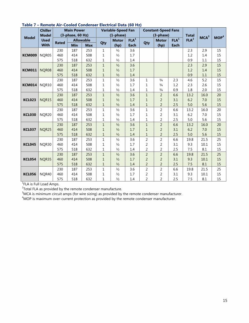
Table 7 – Remote Air-Cooled Condenser Electrical Data (60 Hz)
Model
Chiller
Model
Used
With
Main Power
(3-phase, 60 Hz)
Variable-Speed Fan
(1-phase)
Constant-Speed Fans
(3-phase) Total
FLA2 MCA
3 MOP
4
Rated Allowable
Qty Motor
(hp)
FLA1
Each Qty
Motor
(hp)
FLA1
Each Min Max
KCM009 NQR05
230 187 253 1 ½ 3.6
2.3 2.9 15
460 414 508 1 ½ 1.7
1.2 1.4 15
575 518 632 1 ½ 1.4
0.9 1.1 15
KCM011 NQR08
230 187 253 1 ½ 3.6
2.3 2.9 15
460 414 508 1 ½ 1.7
1.2 1.4 15
575 518 632 1 ½ 1.4
0.9 1.1 15
KCM014 NQR10
230 187 253 1 ½ 3.6 1 ¾ 2.3 4.6 5.2 15
460 414 508 1 ½ 1.7 1 ¾ 1.2 2.3 2.6 15
575 518 632 1 ½ 1.4 1 ¾ 0.9 1.8 2.0 15
KCL023 NQR15
230 187 253 1 ½ 3.6 1 2 6.6 13.2 16.0 20
460 414 508 1 ½ 1.7 1 2 3.1 6.2 7.0 15
575 518 632 1 ½ 1.4 1 2 2.5 5.0 5.6 15
KCL030 NQR20
230 187 253 1 ½ 3.6 1 2 6.6 13.2 16.0 20
460 414 508 1 ½ 1.7 1 2 3.1 6.2 7.0 15
575 518 632 1 ½ 1.4 1 2 2.5 5.0 5.6 15
KCL037 NQR25
230 187 253 1 ½ 3.6 1 2 6.6 13.2 16.0 20
460 414 508 1 ½ 1.7 1 2 3.1 6.2 7.0 15
575 518 632 1 ½ 1.4 1 2 2.5 5.0 5.6 15
KCL045 NQR30
230 187 253 1 ½ 3.6 2 2 6.6 19.8 21.5 25
460 414 508 1 ½ 1.7 2 2 3.1 9.3 10.1 15
575 518 632 1 ½ 1.4 2 2 2.5 7.5 8.1 15
KCL054 NQR35
230 187 253 1 ½ 3.6 2 2 6.6 19.8 21.5 25
460 414 508 1 ½ 1.7 2 2 3.1 9.3 10.1 15
575 518 632 1 ½ 1.4 2 2 2.5 7.5 8.1 15
KCL056 NQR40
230 187 253 1 ½ 3.6 2 2 6.6 19.8 21.5 25
460 414 508 1 ½ 1.7 2 2 3.1 9.3 10.1 15
575 518 632 1 ½ 1.4 2 2 2.5 7.5 8.1 15 1FLA is Full Load Amps.
2Total FLA as provided by the remote condenser manufacture.
3MCA is minimum circuit amps (for wire sizing) as provided by the remote condenser manufacturer.
4MOP is maximum over-current protection as provided by the remote condenser manufacturer.
16
Performance Data
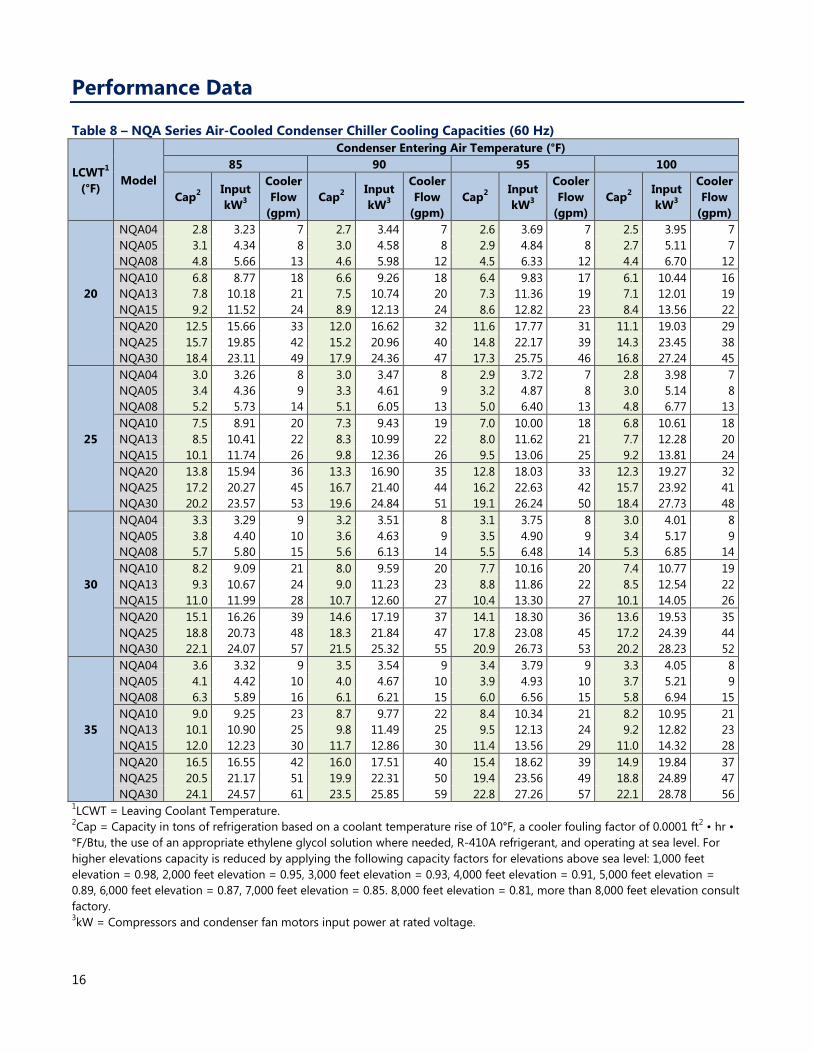
Table 8 – NQA Series Air-Cooled Condenser Chiller Cooling Capacities (60 Hz)
LCWT1
(°F) Model
Condenser Entering Air Temperature (°F)
85 90 95 100
Cap2 Input
kW3
Cooler
Flow
(gpm)
Cap2 Input
kW3
Cooler
Flow
(gpm)
Cap2 Input
kW3
Cooler
Flow
(gpm)
Cap2 Input
kW3
Cooler
Flow
(gpm)
20
NQA04 2.8 3.23 7 2.7 3.44 7 2.6 3.69 7 2.5 3.95 7
NQA05 3.1 4.34 8 3.0 4.58 8 2.9 4.84 8 2.7 5.11 7
NQA08 4.8 5.66 13 4.6 5.98 12 4.5 6.33 12 4.4 6.70 12
NQA10 6.8 8.77 18 6.6 9.26 18 6.4 9.83 17 6.1 10.44 16
NQA13 7.8 10.18 21 7.5 10.74 20 7.3 11.36 19 7.1 12.01 19
NQA15 9.2 11.52 24 8.9 12.13 24 8.6 12.82 23 8.4 13.56 22
NQA20 12.5 15.66 33 12.0 16.62 32 11.6 17.77 31 11.1 19.03 29
NQA25 15.7 19.85 42 15.2 20.96 40 14.8 22.17 39 14.3 23.45 38
NQA30 18.4 23.11 49 17.9 24.36 47 17.3 25.75 46 16.8 27.24 45
25
NQA04 3.0 3.26 8 3.0 3.47 8 2.9 3.72 7 2.8 3.98 7
NQA05 3.4 4.36 9 3.3 4.61 9 3.2 4.87 8 3.0 5.14 8
NQA08 5.2 5.73 14 5.1 6.05 13 5.0 6.40 13 4.8 6.77 13
NQA10 7.5 8.91 20 7.3 9.43 19 7.0 10.00 18 6.8 10.61 18
NQA13 8.5 10.41 22 8.3 10.99 22 8.0 11.62 21 7.7 12.28 20
NQA15 10.1 11.74 26 9.8 12.36 26 9.5 13.06 25 9.2 13.81 24
NQA20 13.8 15.94 36 13.3 16.90 35 12.8 18.03 33 12.3 19.27 32
NQA25 17.2 20.27 45 16.7 21.40 44 16.2 22.63 42 15.7 23.92 41
NQA30 20.2 23.57 53 19.6 24.84 51 19.1 26.24 50 18.4 27.73 48
30
NQA04 3.3 3.29 9 3.2 3.51 8 3.1 3.75 8 3.0 4.01 8
NQA05 3.8 4.40 10 3.6 4.63 9 3.5 4.90 9 3.4 5.17 9
NQA08 5.7 5.80 15 5.6 6.13 14 5.5 6.48 14 5.3 6.85 14
NQA10 8.2 9.09 21 8.0 9.59 20 7.7 10.16 20 7.4 10.77 19
NQA13 9.3 10.67 24 9.0 11.23 23 8.8 11.86 22 8.5 12.54 22
NQA15 11.0 11.99 28 10.7 12.60 27 10.4 13.30 27 10.1 14.05 26
NQA20 15.1 16.26 39 14.6 17.19 37 14.1 18.30 36 13.6 19.53 35
NQA25 18.8 20.73 48 18.3 21.84 47 17.8 23.08 45 17.2 24.39 44
NQA30 22.1 24.07 57 21.5 25.32 55 20.9 26.73 53 20.2 28.23 52
35
NQA04 3.6 3.32 9 3.5 3.54 9 3.4 3.79 9 3.3 4.05 8
NQA05 4.1 4.42 10 4.0 4.67 10 3.9 4.93 10 3.7 5.21 9
NQA08 6.3 5.89 16 6.1 6.21 15 6.0 6.56 15 5.8 6.94 15
NQA10 9.0 9.25 23 8.7 9.77 22 8.4 10.34 21 8.2 10.95 21
NQA13 10.1 10.90 25 9.8 11.49 25 9.5 12.13 24 9.2 12.82 23
NQA15 12.0 12.23 30 11.7 12.86 30 11.4 13.56 29 11.0 14.32 28
NQA20 16.5 16.55 42 16.0 17.51 40 15.4 18.62 39 14.9 19.84 37
NQA25 20.5 21.17 51 19.9 22.31 50 19.4 23.56 49 18.8 24.89 47
NQA30 24.1 24.57 61 23.5 25.85 59 22.8 27.26 57 22.1 28.78 56 1LCWT = Leaving Coolant Temperature.
2Cap = Capacity in tons of refrigeration based on a coolant temperature rise of 10°F, a cooler fouling factor of 0.0001 ft
2 • hr •
°F/Btu, the use of an appropriate ethylene glycol solution where needed, R-410A refrigerant, and operating at sea level. For
higher elevations capacity is reduced by applying the following capacity factors for elevations above sea level: 1,000 feet
elevation = 0.98, 2,000 feet elevation = 0.95, 3,000 feet elevation = 0.93, 4,000 feet elevation = 0.91, 5,000 feet elevation =
0.89, 6,000 feet elevation = 0.87, 7,000 feet elevation = 0.85. 8,000 feet elevation = 0.81, more than 8,000 feet elevation consult
factory. 3kW = Compressors and condenser fan motors input power at rated voltage.

17
Table 8 – NQA Series Air-Cooled Condenser Chiller Cooling Capacities (60 Hz) – Continued
LCWT1
(°F) Model
Condenser Entering Air Temperature (°F)
85 90 95 100
Cap2 Input
kW3
Cooler
Flow
(gpm)
Cap2 Input
kW3
Cooler
Flow
(gpm)
Cap2 Input
kW3
Cooler
Flow
(gpm)
Cap2 Input
kW3
Cooler
Flow
(gpm)
40
NQA04 4.1 3.39 10 4.0 3.60 10 3.9 3.85 9 3.7 4.11 9
NQA05 4.7 4.47 11 4.6 4.71 11 4.4 4.98 11 4.3 5.26 10
NQA08 7.1 6.03 17 7.0 6.34 17 6.8 6.70 16 6.6 7.08 16
NQA10 10.2 9.53 24 9.9 10.05 24 9.5 10.63 23 9.2 11.24 22
NQA13 11.3 11.28 27 11.0 11.88 26 10.7 12.53 25 10.3 13.22 25
NQA15 13.6 12.62 33 13.2 13.26 32 12.8 13.96 31 12.4 14.72 30
NQA20 18.6 17.02 44 18.0 17.99 43 17.4 19.11 42 16.7 20.31 40
NQA25 22.9 21.84 55 22.3 23.00 53 21.6 24.26 52 20.9 25.60 50
NQA30 27.0 25.35 65 26.3 26.63 63 25.5 28.06 61 24.7 29.57 59
45
NQA04 4.4 3.43 11 4.3 3.65 10 4.2 3.91 10 4.1 4.16 10
NQA05 5.1 4.50 12 5.0 4.75 12 4.8 5.01 12 4.7 5.29 11
NQA08 7.8 6.12 19 7.6 6.44 18 7.4 6.80 18 7.2 7.19 17
NQA10 11.0 9.75 26 10.7 10.28 26 10.4 10.85 25 10.0 11.47 24
NQA13 12.3 11.59 29 11.9 12.19 29 11.5 12.85 28 11.2 13.55 27
NQA15 14.7 12.95 35 14.3 13.59 34 13.9 14.29 33 13.4 15.05 32
NQA20 20.1 17.42 48 19.6 18.40 47 18.9 19.51 45 18.2 20.72 44
NQA25 24.9 22.41 60 24.2 23.56 58 23.5 24.83 56 22.7 26.18 54
NQA30 29.4 26.02 70 28.6 27.31 68 27.7 28.73 66 26.8 30.26 64
50
NQA04 4.8 3.49 12 4.7 3.70 11 4.5 3.97 11 4.4 4.23 11
NQA05 5.6 4.53 13 5.4 4.79 13 5.3 5.05 13 5.1 5.33 12
NQA08 8.5 6.23 20 8.3 6.55 20 8.0 6.91 19 7.8 7.29 19
NQA10 11.9 9.99 29 11.6 10.52 28 11.2 11.10 27 10.9 11.72 26
NQA13 13.2 11.92 32 12.9 12.53 31 12.5 13.19 30 12.1 13.90 29
NQA15 15.9 13.32 38 15.5 13.95 37 15.0 14.66 36 14.6 15.42 35
NQA20 21.8 17.84 52 21.2 18.83 51 20.5 19.95 49 19.8 21.16 48
NQA25 26.9 23.02 65 26.2 24.17 63 25.4 25.44 61 24.6 26.81 59
NQA30 31.8 26.77 76 30.9 28.05 74 30.0 29.49 72 29.0 31.02 70
55
NQA04 4.9 3.55 12 5.0 3.79 12 4.9 4.03 12 4.8 4.30 11
NQA05 6.1 4.57 15 5.9 4.83 14 5.7 5.09 14 5.5 5.38 13
NQA08 9.2 6.34 22 9.0 6.66 22 8.7 7.02 21 8.5 7.40 20
NQA10 12.9 10.22 31 12.5 10.80 30 12.1 11.36 29 11.7 11.99 28
NQA13 14.3 12.28 34 13.9 12.89 33 13.4 13.56 32 13.0 14.27 31
NQA15 17.2 13.69 41 16.7 14.38 40 16.2 15.07 39 15.7 15.83 38
NQA20 23.6 18.23 57 22.9 19.33 55 22.2 20.46 53 21.4 21.64 51
NQA25 29.1 23.60 70 28.3 24.85 68 27.4 26.10 66 26.6 27.47 64
NQA30 34.3 27.54 82 33.3 28.93 80 32.4 30.37 78 31.3 31.86 75 1LCWT = Leaving Coolant Temperature.
2Cap = Capacity in tons of refrigeration based on a coolant temperature rise of 10°F, a cooler fouling factor of 0.0001 ft
2 • hr •
°F/Btu, the use of an appropriate ethylene glycol solution where needed, R-410A refrigerant, and operating at sea level. For
higher elevations capacity is reduced by applying the following capacity factors for elevations above sea level: 1,000 feet
elevation = 0.98, 2,000 feet elevation = 0.95, 3,000 feet elevation = 0.93, 4,000 feet elevation = 0.91, 5,000 feet elevation =
0.89, 6,000 feet elevation = 0.87, 7,000 feet elevation = 0.85. 8,000 feet elevation = 0.81, more than 8,000 feet elevation consult
factory. 3kW = Compressors and condenser fan motors input power at rated voltage.
18
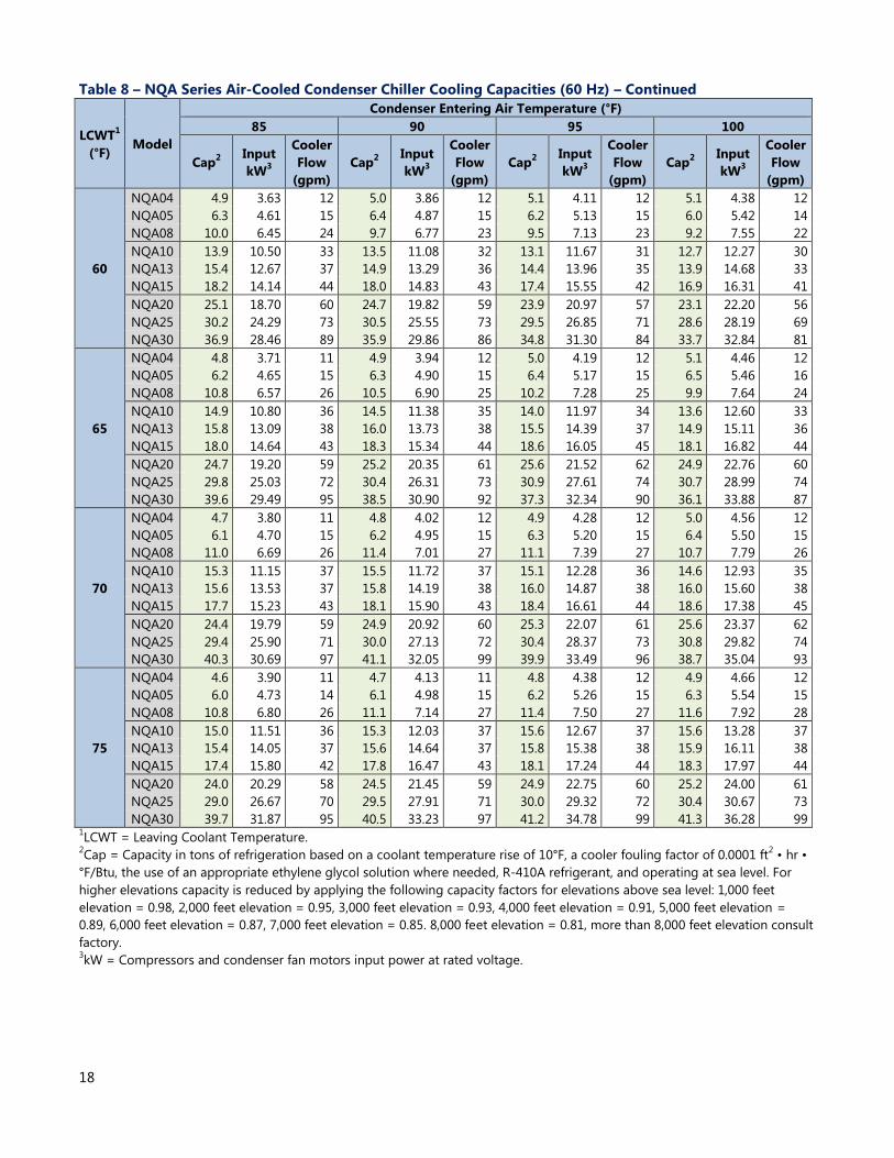
Table 8 – NQA Series Air-Cooled Condenser Chiller Cooling Capacities (60 Hz) – Continued
LCWT1
(°F) Model
Condenser Entering Air Temperature (°F)
85 90 95 100
Cap2 Input
kW3
Cooler
Flow
(gpm)
Cap2 Input
kW3
Cooler
Flow
(gpm)
Cap2 Input
kW3
Cooler
Flow
(gpm)
Cap2 Input
kW3
Cooler
Flow
(gpm)
60
NQA04 4.9 3.63 12 5.0 3.86 12 5.1 4.11 12 5.1 4.38 12
NQA05 6.3 4.61 15 6.4 4.87 15 6.2 5.13 15 6.0 5.42 14
NQA08 10.0 6.45 24 9.7 6.77 23 9.5 7.13 23 9.2 7.55 22
NQA10 13.9 10.50 33 13.5 11.08 32 13.1 11.67 31 12.7 12.27 30
NQA13 15.4 12.67 37 14.9 13.29 36 14.4 13.96 35 13.9 14.68 33
NQA15 18.2 14.14 44 18.0 14.83 43 17.4 15.55 42 16.9 16.31 41
NQA20 25.1 18.70 60 24.7 19.82 59 23.9 20.97 57 23.1 22.20 56
NQA25 30.2 24.29 73 30.5 25.55 73 29.5 26.85 71 28.6 28.19 69
NQA30 36.9 28.46 89 35.9 29.86 86 34.8 31.30 84 33.7 32.84 81
65
NQA04 4.8 3.71 11 4.9 3.94 12 5.0 4.19 12 5.1 4.46 12
NQA05 6.2 4.65 15 6.3 4.90 15 6.4 5.17 15 6.5 5.46 16
NQA08 10.8 6.57 26 10.5 6.90 25 10.2 7.28 25 9.9 7.64 24
NQA10 14.9 10.80 36 14.5 11.38 35 14.0 11.97 34 13.6 12.60 33
NQA13 15.8 13.09 38 16.0 13.73 38 15.5 14.39 37 14.9 15.11 36
NQA15 18.0 14.64 43 18.3 15.34 44 18.6 16.05 45 18.1 16.82 44
NQA20 24.7 19.20 59 25.2 20.35 61 25.6 21.52 62 24.9 22.76 60
NQA25 29.8 25.03 72 30.4 26.31 73 30.9 27.61 74 30.7 28.99 74
NQA30 39.6 29.49 95 38.5 30.90 92 37.3 32.34 90 36.1 33.88 87
70
NQA04 4.7 3.80 11 4.8 4.02 12 4.9 4.28 12 5.0 4.56 12
NQA05 6.1 4.70 15 6.2 4.95 15 6.3 5.20 15 6.4 5.50 15
NQA08 11.0 6.69 26 11.4 7.01 27 11.1 7.39 27 10.7 7.79 26
NQA10 15.3 11.15 37 15.5 11.72 37 15.1 12.28 36 14.6 12.93 35
NQA13 15.6 13.53 37 15.8 14.19 38 16.0 14.87 38 16.0 15.60 38
NQA15 17.7 15.23 43 18.1 15.90 43 18.4 16.61 44 18.6 17.38 45
NQA20 24.4 19.79 59 24.9 20.92 60 25.3 22.07 61 25.6 23.37 62
NQA25 29.4 25.90 71 30.0 27.13 72 30.4 28.37 73 30.8 29.82 74
NQA30 40.3 30.69 97 41.1 32.05 99 39.9 33.49 96 38.7 35.04 93
75
NQA04 4.6 3.90 11 4.7 4.13 11 4.8 4.38 12 4.9 4.66 12
NQA05 6.0 4.73 14 6.1 4.98 15 6.2 5.26 15 6.3 5.54 15
NQA08 10.8 6.80 26 11.1 7.14 27 11.4 7.50 27 11.6 7.92 28
NQA10 15.0 11.51 36 15.3 12.03 37 15.6 12.67 37 15.6 13.28 37
NQA13 15.4 14.05 37 15.6 14.64 37 15.8 15.38 38 15.9 16.11 38
NQA15 17.4 15.80 42 17.8 16.47 43 18.1 17.24 44 18.3 17.97 44
NQA20 24.0 20.29 58 24.5 21.45 59 24.9 22.75 60 25.2 24.00 61
NQA25 29.0 26.67 70 29.5 27.91 71 30.0 29.32 72 30.4 30.67 73
NQA30 39.7 31.87 95 40.5 33.23 97 41.2 34.78 99 41.3 36.28 99 1LCWT = Leaving Coolant Temperature.
2Cap = Capacity in tons of refrigeration based on a coolant temperature rise of 10°F, a cooler fouling factor of 0.0001 ft
2 • hr •
°F/Btu, the use of an appropriate ethylene glycol solution where needed, R-410A refrigerant, and operating at sea level. For
higher elevations capacity is reduced by applying the following capacity factors for elevations above sea level: 1,000 feet
elevation = 0.98, 2,000 feet elevation = 0.95, 3,000 feet elevation = 0.93, 4,000 feet elevation = 0.91, 5,000 feet elevation =
0.89, 6,000 feet elevation = 0.87, 7,000 feet elevation = 0.85. 8,000 feet elevation = 0.81, more than 8,000 feet elevation consult
factory. 3kW = Compressors and condenser fan motors input power at rated voltage.
19
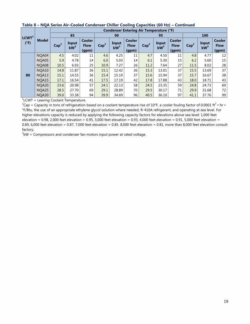
Table 8 – NQA Series Air-Cooled Condenser Chiller Cooling Capacities (60 Hz) – Continued
LCWT1
(°F) Model
Condenser Entering Air Temperature (°F)
85 90 95 100
Cap2 Input
kW3
Cooler
Flow
(gpm)
Cap2 Input
kW3
Cooler
Flow
(gpm)
Cap2 Input
kW3
Cooler
Flow
(gpm)
Cap2 Input
kW3
Cooler
Flow
(gpm)
80
NQA04 4.5 4.02 11 4.6 4.25 11 4.7 4.50 11 4.8 4.77 12
NQA05 5.9 4.78 14 6.0 5.03 14 6.1 5.30 15 6.2 5.60 15
NQA08 10.5 6.93 25 10.9 7.27 26 11.2 7.64 27 11.5 8.02 28
NQA10 14.8 11.87 36 15.1 12.42 36 15.3 13.01 37 15.5 13.69 37
NQA13 15.1 14.55 36 15.4 15.19 37 15.6 15.94 37 15.7 16.67 38
NQA15 17.1 16.54 41 17.5 17.19 42 17.8 17.88 43 18.0 18.71 43
NQA20 23.6 20.98 57 24.1 22.13 58 24.5 23.35 59 24.8 24.73 60
NQA25 28.5 27.70 69 29.1 28.89 70 29.5 30.17 71 29.9 31.68 72
NQA30 39.0 33.38 94 39.9 34.69 96 40.5 36.10 97 41.1 37.76 99 1LCWT = Leaving Coolant Temperature.
2Cap = Capacity in tons of refrigeration based on a coolant temperature rise of 10°F, a cooler fouling factor of 0.0001 ft
2 • hr •
°F/Btu, the use of an appropriate ethylene glycol solution where needed, R-410A refrigerant, and operating at sea level. For
higher elevations capacity is reduced by applying the following capacity factors for elevations above sea level: 1,000 feet
elevation = 0.98, 2,000 feet elevation = 0.95, 3,000 feet elevation = 0.93, 4,000 feet elevation = 0.91, 5,000 feet elevation =
0.89, 6,000 feet elevation = 0.87, 7,000 feet elevation = 0.85. 8,000 feet elevation = 0.81, more than 8,000 feet elevation consult
factory. 3kW = Compressors and condenser fan motors input power at rated voltage.
20
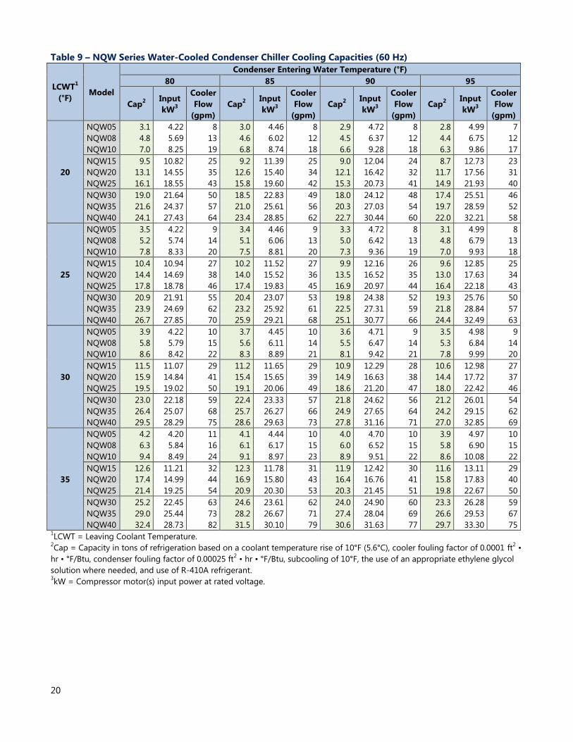
Table 9 – NQW Series Water-Cooled Condenser Chiller Cooling Capacities (60 Hz)
LCWT1
(°F) Model
Condenser Entering Water Temperature (°F)
80 85 90 95
Cap2 Input
kW3
Cooler
Flow
(gpm)
Cap2 Input
kW3
Cooler
Flow
(gpm)
Cap2 Input
kW3
Cooler
Flow
(gpm)
Cap2 Input
kW3
Cooler
Flow
(gpm)
20
NQW05 3.1 4.22 8 3.0 4.46 8 2.9 4.72 8 2.8 4.99 7
NQW08 4.8 5.69 13 4.6 6.02 12 4.5 6.37 12 4.4 6.75 12
NQW10 7.0 8.25 19 6.8 8.74 18 6.6 9.28 18 6.3 9.86 17
NQW15 9.5 10.82 25 9.2 11.39 25 9.0 12.04 24 8.7 12.73 23
NQW20 13.1 14.55 35 12.6 15.40 34 12.1 16.42 32 11.7 17.56 31
NQW25 16.1 18.55 43 15.8 19.60 42 15.3 20.73 41 14.9 21.93 40
NQW30 19.0 21.64 50 18.5 22.83 49 18.0 24.12 48 17.4 25.51 46
NQW35 21.6 24.37 57 21.0 25.61 56 20.3 27.03 54 19.7 28.59 52
NQW40 24.1 27.43 64 23.4 28.85 62 22.7 30.44 60 22.0 32.21 58
25
NQW05 3.5 4.22 9 3.4 4.46 9 3.3 4.72 8 3.1 4.99 8
NQW08 5.2 5.74 14 5.1 6.06 13 5.0 6.42 13 4.8 6.79 13
NQW10 7.8 8.33 20 7.5 8.81 20 7.3 9.36 19 7.0 9.93 18
NQW15 10.4 10.94 27 10.2 11.52 27 9.9 12.16 26 9.6 12.85 25
NQW20 14.4 14.69 38 14.0 15.52 36 13.5 16.52 35 13.0 17.63 34
NQW25 17.8 18.78 46 17.4 19.83 45 16.9 20.97 44 16.4 22.18 43
NQW30 20.9 21.91 55 20.4 23.07 53 19.8 24.38 52 19.3 25.76 50
NQW35 23.9 24.69 62 23.2 25.92 61 22.5 27.31 59 21.8 28.84 57
NQW40 26.7 27.85 70 25.9 29.21 68 25.1 30.77 66 24.4 32.49 63
30
NQW05 3.9 4.22 10 3.7 4.45 10 3.6 4.71 9 3.5 4.98 9
NQW08 5.8 5.79 15 5.6 6.11 14 5.5 6.47 14 5.3 6.84 14
NQW10 8.6 8.42 22 8.3 8.89 21 8.1 9.42 21 7.8 9.99 20
NQW15 11.5 11.07 29 11.2 11.65 29 10.9 12.29 28 10.6 12.98 27
NQW20 15.9 14.84 41 15.4 15.65 39 14.9 16.63 38 14.4 17.72 37
NQW25 19.5 19.02 50 19.1 20.06 49 18.6 21.20 47 18.0 22.42 46
NQW30 23.0 22.18 59 22.4 23.33 57 21.8 24.62 56 21.2 26.01 54
NQW35 26.4 25.07 68 25.7 26.27 66 24.9 27.65 64 24.2 29.15 62
NQW40 29.5 28.29 75 28.6 29.63 73 27.8 31.16 71 27.0 32.85 69
35
NQW05 4.2 4.20 11 4.1 4.44 10 4.0 4.70 10 3.9 4.97 10
NQW08 6.3 5.84 16 6.1 6.17 15 6.0 6.52 15 5.8 6.90 15
NQW10 9.4 8.49 24 9.1 8.97 23 8.9 9.51 22 8.6 10.08 22
NQW15 12.6 11.21 32 12.3 11.78 31 11.9 12.42 30 11.6 13.11 29
NQW20 17.4 14.99 44 16.9 15.80 43 16.4 16.76 41 15.8 17.83 40
NQW25 21.4 19.25 54 20.9 20.30 53 20.3 21.45 51 19.8 22.67 50
NQW30 25.2 22.45 63 24.6 23.61 62 24.0 24.90 60 23.3 26.28 59
NQW35 29.0 25.44 73 28.2 26.67 71 27.4 28.04 69 26.6 29.53 67
NQW40 32.4 28.73 82 31.5 30.10 79 30.6 31.63 77 29.7 33.30 75 1LCWT = Leaving Coolant Temperature.
2Cap = Capacity in tons of refrigeration based on a coolant temperature rise of 10°F (5.6°C), cooler fouling factor of 0.0001 ft
2 •
hr • °F/Btu, condenser fouling factor of 0.00025 ft2 • hr • °F/Btu, subcooling of 10°F, the use of an appropriate ethylene glycol
solution where needed, and use of R-410A refrigerant. 3kW = Compressor motor(s) input power at rated voltage.
21
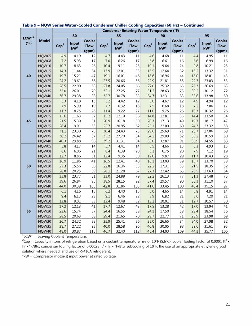
Table 9 – NQW Series Water-Cooled Condenser Chiller Cooling Capacities (60 Hz) – Continued
LCWT1
(°F) Model
Condenser Entering Water Temperature (°F)
80 85 90 95
Cap2 Input
kW3
Cooler
Flow
(gpm)
Cap2 Input
kW3
Cooler
Flow
(gpm)
Cap2 Input
kW3
Cooler
Flow
(gpm)
Cap2 Input
kW3
Cooler
Flow
(gpm)
40
NQW05 4.9 4.19 12 4.7 4.43 11 4.6 4.68 11 4.4 4.95 11
NQW08 7.2 5.93 17 7.0 6.26 17 6.8 6.61 16 6.6 6.99 16
NQW10 10.7 8.63 26 10.4 9.11 25 10.1 9.64 24 9.8 10.21 23
NQW15 14.3 11.44 34 13.9 12.01 33 13.5 12.64 32 13.2 13.32 31
NQW20 19.7 15.21 47 19.1 16.01 46 18.6 16.96 44 18.0 18.01 43
NQW25 24.2 19.61 58 23.5 20.66 56 22.9 21.81 55 22.3 23.03 53
NQW30 28.5 22.90 68 27.8 24.05 66 27.0 25.32 65 26.3 26.69 63
NQW35 33.0 26.01 79 32.1 27.25 77 31.2 28.63 75 30.2 30.12 72
NQW40 36.7 29.38 88 35.7 30.78 85 34.7 32.31 83 33.6 33.98 80
45
NQW05 5.3 4.18 13 5.2 4.42 12 5.0 4.67 12 4.9 4.94 12
NQW08 7.9 5.99 19 7.7 6.32 18 7.5 6.68 18 7.2 7.06 17
NQW10 11.7 8.75 28 11.4 9.22 27 11.0 9.75 26 10.7 10.32 26
NQW15 15.6 11.63 37 15.2 12.19 36 14.8 12.81 35 14.4 13.50 34
NQW20 21.5 15.39 51 20.9 16.18 50 20.3 17.13 49 19.7 18.17 47
NQW25 26.4 19.91 63 25.7 20.95 62 25.1 22.09 60 24.3 23.32 58
NQW30 31.1 23.30 75 30.4 24.43 73 29.6 25.69 71 28.7 27.06 69
NQW35 36.2 26.42 87 35.2 27.70 84 34.2 29.09 82 33.2 30.59 80
NQW40 40.3 29.88 96 39.2 31.31 94 38.0 32.87 91 36.9 34.55 88
50
NQW05 5.8 4.17 14 5.7 4.41 14 5.5 4.66 13 5.3 4.93 13
NQW08 8.6 6.06 21 8.4 6.39 20 8.1 6.75 20 7.9 7.12 19
NQW10 12.7 8.86 31 12.4 9.35 30 12.0 9.87 29 11.7 10.43 28
NQW15 16.9 11.86 41 16.5 12.41 40 16.1 13.03 39 15.7 13.70 38
NQW20 23.3 15.56 56 22.8 16.36 55 22.2 17.31 53 21.5 18.35 52
NQW25 28.8 20.25 69 28.1 21.28 67 27.3 22.42 65 26.5 23.63 64
NQW30 33.8 23.77 81 33.0 24.88 79 32.2 26.13 77 31.3 27.48 75
NQW35 39.6 26.84 95 38.5 28.15 92 37.4 29.57 90 36.3 31.10 87
NQW40 44.0 30.39 105 42.8 31.86 103 41.6 33.45 100 40.4 35.15 97
55
NQW05 6.1 4.16 15 6.2 4.40 15 6.0 4.65 14 5.8 4.91 14
NQW08 9.4 6.13 23 9.1 6.46 22 8.9 6.82 21 8.6 7.20 21
NQW10 13.8 9.01 33 13.4 9.48 32 13.1 10.01 31 12.7 10.57 30
NQW15 17.2 12.13 41 17.7 12.67 43 17.5 13.28 42 17.0 13.94 41
NQW20 23.6 15.74 57 24.4 16.55 58 24.1 17.50 58 23.4 18.54 56
NQW25 28.5 20.63 68 29.4 21.65 70 29.7 22.77 71 28.9 23.98 69
NQW30 36.7 24.32 88 35.9 25.41 86 35.0 26.65 84 34.0 27.98 82
NQW35 38.7 27.22 93 40.0 28.58 96 40.8 30.05 98 39.6 31.61 95
NQW40 48.0 30.87 115 46.7 32.40 112 45.4 34.03 109 44.1 35.77 106 1LCWT = Leaving Coolant Temperature.
2Cap = Capacity in tons of refrigeration based on a coolant temperature rise of 10°F (5.6°C), cooler fouling factor of 0.0001 ft
2 •
hr • °F/Btu, condenser fouling factor of 0.00025 ft2 • hr • °F/Btu, subcooling of 10°F, the use of an appropriate ethylene glycol
solution where needed, and use of R-410A refrigerant. 3kW = Compressor motor(s) input power at rated voltage.
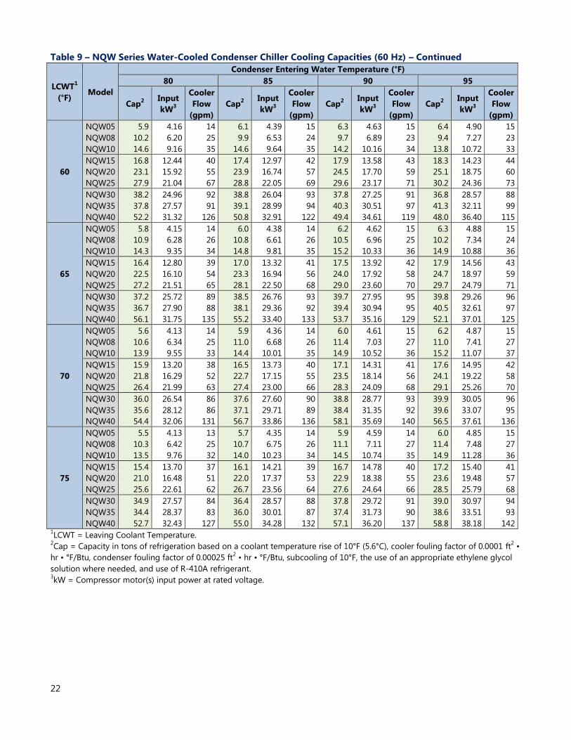
22
Table 9 – NQW Series Water-Cooled Condenser Chiller Cooling Capacities (60 Hz) – Continued
LCWT1
(°F) Model
Condenser Entering Water Temperature (°F)
80 85 90 95
Cap2 Input
kW3
Cooler
Flow
(gpm)
Cap2 Input
kW3
Cooler
Flow
(gpm)
Cap2 Input
kW3
Cooler
Flow
(gpm)
Cap2 Input
kW3
Cooler
Flow
(gpm)
60
NQW05 5.9 4.16 14 6.1 4.39 15 6.3 4.63 15 6.4 4.90 15
NQW08 10.2 6.20 25 9.9 6.53 24 9.7 6.89 23 9.4 7.27 23
NQW10 14.6 9.16 35 14.6 9.64 35 14.2 10.16 34 13.8 10.72 33
NQW15 16.8 12.44 40 17.4 12.97 42 17.9 13.58 43 18.3 14.23 44
NQW20 23.1 15.92 55 23.9 16.74 57 24.5 17.70 59 25.1 18.75 60
NQW25 27.9 21.04 67 28.8 22.05 69 29.6 23.17 71 30.2 24.36 73
NQW30 38.2 24.96 92 38.8 26.04 93 37.8 27.25 91 36.8 28.57 88
NQW35 37.8 27.57 91 39.1 28.99 94 40.3 30.51 97 41.3 32.11 99
NQW40 52.2 31.32 126 50.8 32.91 122 49.4 34.61 119 48.0 36.40 115
65
NQW05 5.8 4.15 14 6.0 4.38 14 6.2 4.62 15 6.3 4.88 15
NQW08 10.9 6.28 26 10.8 6.61 26 10.5 6.96 25 10.2 7.34 24
NQW10 14.3 9.35 34 14.8 9.81 35 15.2 10.33 36 14.9 10.88 36
NQW15 16.4 12.80 39 17.0 13.32 41 17.5 13.92 42 17.9 14.56 43
NQW20 22.5 16.10 54 23.3 16.94 56 24.0 17.92 58 24.7 18.97 59
NQW25 27.2 21.51 65 28.1 22.50 68 29.0 23.60 70 29.7 24.79 71
NQW30 37.2 25.72 89 38.5 26.76 93 39.7 27.95 95 39.8 29.26 96
NQW35 36.7 27.90 88 38.1 29.36 92 39.4 30.94 95 40.5 32.61 97
NQW40 56.1 31.75 135 55.2 33.40 133 53.7 35.16 129 52.1 37.01 125
70
NQW05 5.6 4.13 14 5.9 4.36 14 6.0 4.61 15 6.2 4.87 15
NQW08 10.6 6.34 25 11.0 6.68 26 11.4 7.03 27 11.0 7.41 27
NQW10 13.9 9.55 33 14.4 10.01 35 14.9 10.52 36 15.2 11.07 37
NQW15 15.9 13.20 38 16.5 13.73 40 17.1 14.31 41 17.6 14.95 42
NQW20 21.8 16.29 52 22.7 17.15 55 23.5 18.14 56 24.1 19.22 58
NQW25 26.4 21.99 63 27.4 23.00 66 28.3 24.09 68 29.1 25.26 70
NQW30 36.0 26.54 86 37.6 27.60 90 38.8 28.77 93 39.9 30.05 96
NQW35 35.6 28.12 86 37.1 29.71 89 38.4 31.35 92 39.6 33.07 95
NQW40 54.4 32.06 131 56.7 33.86 136 58.1 35.69 140 56.5 37.61 136
75
NQW05 5.5 4.13 13 5.7 4.35 14 5.9 4.59 14 6.0 4.85 15
NQW08 10.3 6.42 25 10.7 6.75 26 11.1 7.11 27 11.4 7.48 27
NQW10 13.5 9.76 32 14.0 10.23 34 14.5 10.74 35 14.9 11.28 36
NQW15 15.4 13.70 37 16.1 14.21 39 16.7 14.78 40 17.2 15.40 41
NQW20 21.0 16.48 51 22.0 17.37 53 22.9 18.38 55 23.6 19.48 57
NQW25 25.6 22.61 62 26.7 23.56 64 27.6 24.64 66 28.5 25.79 68
NQW30 34.9 27.57 84 36.4 28.57 88 37.8 29.72 91 39.0 30.97 94
NQW35 34.4 28.37 83 36.0 30.01 87 37.4 31.73 90 38.6 33.51 93
NQW40 52.7 32.43 127 55.0 34.28 132 57.1 36.20 137 58.8 38.18 142 1LCWT = Leaving Coolant Temperature.
2Cap = Capacity in tons of refrigeration based on a coolant temperature rise of 10°F (5.6°C), cooler fouling factor of 0.0001 ft
2 •
hr • °F/Btu, condenser fouling factor of 0.00025 ft2 • hr • °F/Btu, subcooling of 10°F, the use of an appropriate ethylene glycol
solution where needed, and use of R-410A refrigerant. 3kW = Compressor motor(s) input power at rated voltage.
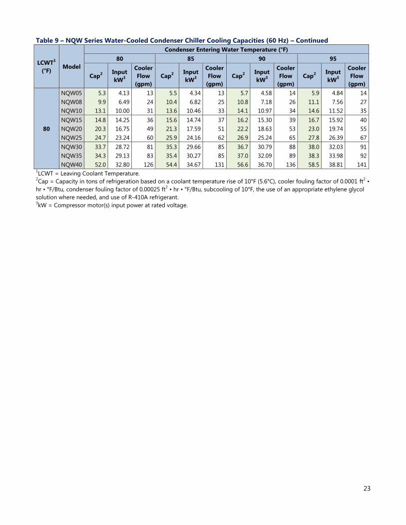
23
Table 9 – NQW Series Water-Cooled Condenser Chiller Cooling Capacities (60 Hz) – Continued
LCWT1
(°F) Model
Condenser Entering Water Temperature (°F)
80 85 90 95
Cap2 Input
kW3
Cooler
Flow
(gpm)
Cap2 Input
kW3
Cooler
Flow
(gpm)
Cap2 Input
kW3
Cooler
Flow
(gpm)
Cap2 Input
kW3
Cooler
Flow
(gpm)
80
NQW05 5.3 4.13 13 5.5 4.34 13 5.7 4.58 14 5.9 4.84 14
NQW08 9.9 6.49 24 10.4 6.82 25 10.8 7.18 26 11.1 7.56 27
NQW10 13.1 10.00 31 13.6 10.46 33 14.1 10.97 34 14.6 11.52 35
NQW15 14.8 14.25 36 15.6 14.74 37 16.2 15.30 39 16.7 15.92 40
NQW20 20.3 16.75 49 21.3 17.59 51 22.2 18.63 53 23.0 19.74 55
NQW25 24.7 23.24 60 25.9 24.16 62 26.9 25.24 65 27.8 26.39 67
NQW30 33.7 28.72 81 35.3 29.66 85 36.7 30.79 88 38.0 32.03 91
NQW35 34.3 29.13 83 35.4 30.27 85 37.0 32.09 89 38.3 33.98 92
NQW40 52.0 32.80 126 54.4 34.67 131 56.6 36.70 136 58.5 38.81 141 1LCWT = Leaving Coolant Temperature.
2Cap = Capacity in tons of refrigeration based on a coolant temperature rise of 10°F (5.6°C), cooler fouling factor of 0.0001 ft
2 •
hr • °F/Btu, condenser fouling factor of 0.00025 ft2 • hr • °F/Btu, subcooling of 10°F, the use of an appropriate ethylene glycol
solution where needed, and use of R-410A refrigerant. 3kW = Compressor motor(s) input power at rated voltage.

24
Table 10 – NQR Series Remote Air-Cooled Condenser Chiller Cooling Capacities (60 Hz)
LCWT1
(°F) Model
Condenser Entering Air Temperature (°F)
85 90 95 100
Cap2 Input
kW3
Cooler
Flow
(gpm)
Cap2 Input
kW3
Cooler
Flow
(gpm)
Cap2 Input
kW3
Cooler
Flow
(gpm)
Cap2 Input
kW3
Cooler
Flow
(gpm)
20
NQR05 3.2 4.05 9 3.1 4.29 8 3.0 4.54 8 2.9 4.80 8
NQR08 4.7 5.71 13 4.6 6.03 12 4.5 6.38 12 4.4 6.75 12
NQR10 7.0 8.35 19 6.8 8.84 18 6.5 9.38 17 6.3 9.96 17
NQR15 9.4 10.98 25 9.1 11.56 24 8.9 12.21 24 8.6 12.91 23
NQR20 12.9 14.87 34 12.4 15.75 33 12.0 16.80 32 11.5 17.97 31
NQR25 16.1 18.78 43 15.7 19.84 42 15.2 20.98 40 14.8 22.20 39
NQR30 18.9 21.97 50 18.4 23.16 49 17.8 24.47 47 17.3 25.87 46
NQR35 21.2 25.15 56 20.6 26.45 55 19.9 27.94 53 19.3 29.58 51
NQR40 23.8 28.12 63 23.1 29.54 61 22.4 31.19 59 21.6 33.03 58
25
NQR05 3.6 4.06 9 3.5 4.29 9 3.3 4.54 9 3.2 4.80 8
NQR08 5.2 5.78 14 5.1 6.10 13 4.9 6.46 13 4.8 6.83 13
NQR10 7.7 8.47 20 7.5 8.96 19 7.2 9.51 19 7.0 10.09 18
NQR15 10.3 11.16 27 10.1 11.74 26 9.8 12.40 26 9.5 13.10 25
NQR20 14.2 15.10 37 13.7 15.96 36 13.3 17.00 35 12.7 18.15 33
NQR25 17.6 19.11 46 17.2 20.17 45 16.8 21.33 44 16.3 22.56 42
NQR30 20.7 22.34 54 20.2 23.52 53 19.6 24.84 51 19.0 26.25 50
NQR35 23.4 25.63 61 22.7 26.91 59 22.1 28.38 57 21.4 30.00 56
NQR40 26.3 28.65 68 25.5 30.06 66 24.7 31.69 64 23.9 33.49 62
30
NQR05 3.9 4.07 10 3.8 4.30 10 3.7 4.55 9 3.6 4.81 9
NQR08 5.7 5.86 15 5.6 6.18 14 5.4 6.54 14 5.3 6.92 13
NQR10 8.5 8.61 22 8.2 9.09 21 8.0 9.63 20 7.7 10.22 20
NQR15 11.3 11.35 29 11.1 11.94 28 10.8 12.59 27 10.4 13.29 27
NQR20 15.6 15.34 40 15.1 16.19 39 14.6 17.22 37 14.1 18.35 36
NQR25 19.3 19.45 49 18.9 20.51 48 18.4 21.68 47 17.8 22.92 46
NQR30 22.8 22.73 58 22.2 23.90 57 21.6 25.23 55 20.9 26.64 54
NQR35 25.7 26.17 66 25.0 27.43 64 24.3 28.89 62 23.5 30.49 60
NQR40 28.9 29.26 74 28.1 30.65 72 27.2 32.26 70 26.4 34.04 68
35
NQR05 4.3 4.08 11 4.2 4.30 11 4.1 4.55 10 3.9 4.81 10
NQR08 6.3 5.95 16 6.1 6.27 15 5.9 6.63 15 5.8 7.01 15
NQR10 9.3 8.74 23 9.0 9.23 23 8.7 9.78 22 8.4 10.36 21
NQR15 12.4 11.55 31 12.1 12.14 30 11.8 12.80 30 11.4 13.50 29
NQR20 17.1 15.58 43 16.6 16.44 42 16.0 17.46 40 15.5 18.58 39
NQR25 21.1 19.81 53 20.6 20.88 52 20.1 22.05 50 19.5 23.30 49
NQR30 24.9 23.13 63 24.3 24.32 61 23.6 25.64 59 22.9 27.06 58
NQR35 28.2 26.73 71 27.5 28.02 69 26.6 29.48 67 25.8 31.08 65
NQR40 31.7 29.90 80 30.8 31.32 77 29.9 32.93 75 29.0 34.70 73 1LCWT = Leaving Coolant Temperature.
2Cap = Capacity in tons of refrigeration based on a coolant temperature rise of 10°F, a cooler fouling factor of 0.0001 ft
2 • hr •
°F/Btu, the use of an appropriate ethylene glycol solution where needed, R-410A refrigerant, and operating at sea level. For
higher elevations capacity is reduced by applying the following capacity factors for elevations above sea level: 1,000 feet
elevation = 0.98, 2,000 feet elevation = 0.95, 3,000 feet elevation = 0.93, 4,000 feet elevation = 0.91, 5,000 feet elevation =
0.89, 6,000 feet elevation = 0.87, 7,000 feet elevation = 0.85. 8,000 feet elevation = 0.81, more than 8,000 feet elevation consult
factory. 3kW = Compressors and condenser fan motors input power at rated voltage.

25
Table 10 –NQR Series Remote Air-Cooled Condenser Chiller Cooling Capacities (60 Hz) – Continued
LCWT1
(°F) Model
Condenser Entering Air Temperature (°F)
85 90 95 100
Cap2 Input
kW3
Cooler
Flow
(gpm)
Cap2 Input
kW3
Cooler
Flow
(gpm)
Cap2 Input
kW3
Cooler
Flow
(gpm)
Cap2 Input
kW3
Cooler
Flow
(gpm)
40
NQR05 4.9 4.09 12 4.8 4.31 12 4.7 4.55 11 4.5 4.82 11
NQR08 7.1 6.09 17 6.9 6.42 17 6.7 6.78 16 6.5 7.16 16
NQR10 10.5 8.97 25 10.2 9.46 24 9.9 10.00 24 9.6 10.58 23
NQR15 14.0 11.88 33 13.6 12.46 33 13.3 13.12 32 12.9 13.82 31
NQR20 19.2 15.96 46 18.6 16.82 45 18.1 17.83 43 17.4 18.94 42
NQR25 23.7 20.36 57 23.1 21.41 55 22.5 22.59 54 21.9 23.84 52
NQR30 28.0 23.78 67 27.3 24.95 65 26.5 26.27 63 25.7 27.69 62
NQR35 31.9 27.59 76 31.0 28.91 74 30.1 30.38 72 29.1 31.98 70
NQR40 35.7 30.85 85 34.7 32.30 83 33.6 33.92 81 32.6 35.69 78
45
NQR05 5.4 4.09 13 5.3 4.32 13 5.1 4.56 12 5.0 4.82 12
NQR08 7.8 6.20 19 7.6 6.52 18 7.3 6.87 18 7.1 7.27 17
NQR10 11.4 9.15 27 11.1 9.66 27 10.8 10.18 26 10.4 10.77 25
NQR15 15.2 12.14 36 14.8 12.75 36 14.4 13.38 35 14.0 14.09 34
NQR20 20.9 16.24 50 20.3 17.17 49 19.7 18.14 47 19.1 19.25 46
NQR25 25.9 20.78 62 25.2 21.89 60 24.5 23.03 59 23.8 24.29 57
NQR30 30.4 24.31 73 29.7 25.46 71 28.8 26.87 69 28.0 28.24 67
NQR35 34.8 28.30 83 33.8 29.68 81 32.8 31.13 79 31.8 32.75 76
NQR40 38.9 31.65 93 37.9 33.17 91 36.8 34.76 88 35.6 36.55 85
50
NQR05 5.9 4.10 14 5.7 4.32 14 5.6 4.56 13 5.4 4.82 13
NQR08 8.4 6.31 20 8.2 6.63 20 8.0 7.01 19 7.8 7.38 19
NQR10 12.4 9.34 30 12.0 9.85 29 11.7 10.40 28 11.3 10.96 27
NQR15 16.5 12.45 40 16.1 13.06 39 15.7 13.71 38 15.2 14.41 36
NQR20 22.7 16.55 54 22.1 17.49 53 21.4 18.52 51 20.7 19.63 50
NQR25 28.1 21.26 67 27.4 22.37 66 26.6 23.55 64 25.8 24.81 62
NQR30 33.0 24.94 79 32.2 26.16 77 31.3 27.48 75 30.4 28.90 73
NQR35 37.9 28.99 91 36.8 30.44 88 35.7 31.98 86 34.7 33.57 83
NQR40 42.4 32.43 102 41.2 34.02 99 40.0 35.72 96 38.8 37.55 93
55
NQR05 6.0 4.11 14 6.2 4.33 15 6.1 4.57 15 5.9 4.82 14
NQR08 9.2 6.42 22 8.9 6.75 21 8.7 7.14 21 8.4 7.53 20
NQR10 13.4 9.55 32 13.0 10.06 31 12.7 10.61 30 12.3 11.19 29
NQR15 17.8 12.79 43 17.4 13.40 42 16.9 14.05 41 16.4 14.75 39
NQR20 24.5 16.88 59 23.9 17.83 57 23.2 18.87 56 22.5 20.00 54
NQR25 29.4 21.78 71 29.6 22.89 71 28.8 24.07 69 28.0 25.33 67
NQR30 35.7 25.64 86 34.8 26.86 84 33.9 28.18 81 32.9 29.59 79
NQR35 40.8 29.73 98 40.0 31.23 96 38.8 32.81 93 37.6 34.50 90
NQR40 46.0 33.26 111 44.8 34.91 107 43.5 36.66 104 42.1 38.53 101 1LCWT = Leaving Coolant Temperature.
2Cap = Capacity in tons of refrigeration based on a coolant temperature rise of 10°F, a cooler fouling factor of 0.0001 ft
2 • hr •
°F/Btu, the use of an appropriate ethylene glycol solution where needed, R-410A refrigerant, and operating at sea level. For
higher elevations capacity is reduced by applying the following capacity factors for elevations above sea level: 1,000 feet
elevation = 0.98, 2,000 feet elevation = 0.95, 3,000 feet elevation = 0.93, 4,000 feet elevation = 0.91, 5,000 feet elevation =
0.89, 6,000 feet elevation = 0.87, 7,000 feet elevation = 0.85. 8,000 feet elevation = 0.81, more than 8,000 feet elevation consult
factory. 3kW = Compressors and condenser fan motors input power at rated voltage.
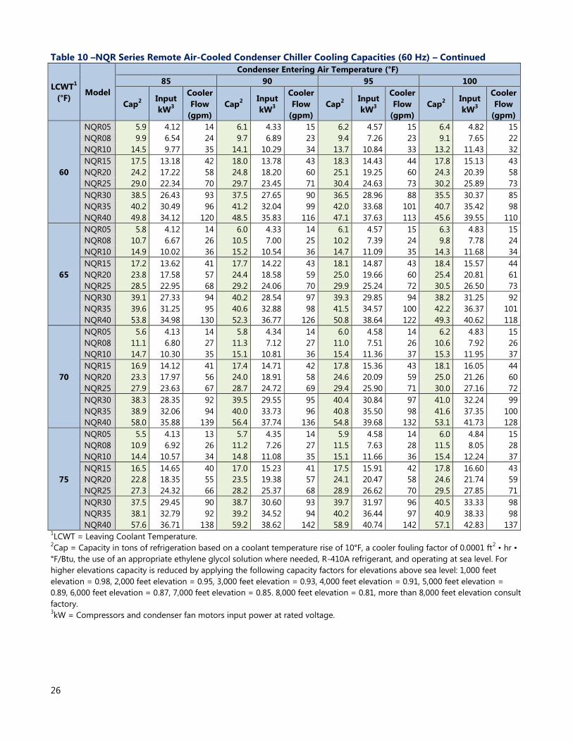
26
Table 10 –NQR Series Remote Air-Cooled Condenser Chiller Cooling Capacities (60 Hz) – Continued
LCWT1
(°F) Model
Condenser Entering Air Temperature (°F)
85 90 95 100
Cap2 Input
kW3
Cooler
Flow
(gpm)
Cap2 Input
kW3
Cooler
Flow
(gpm)
Cap2 Input
kW3
Cooler
Flow
(gpm)
Cap2 Input
kW3
Cooler
Flow
(gpm)
60
NQR05 5.9 4.12 14 6.1 4.33 15 6.2 4.57 15 6.4 4.82 15
NQR08 9.9 6.54 24 9.7 6.89 23 9.4 7.26 23 9.1 7.65 22
NQR10 14.5 9.77 35 14.1 10.29 34 13.7 10.84 33 13.2 11.43 32
NQR15 17.5 13.18 42 18.0 13.78 43 18.3 14.43 44 17.8 15.13 43
NQR20 24.2 17.22 58 24.8 18.20 60 25.1 19.25 60 24.3 20.39 58
NQR25 29.0 22.34 70 29.7 23.45 71 30.4 24.63 73 30.2 25.89 73
NQR30 38.5 26.43 93 37.5 27.65 90 36.5 28.96 88 35.5 30.37 85
NQR35 40.2 30.49 96 41.2 32.04 99 42.0 33.68 101 40.7 35.42 98
NQR40 49.8 34.12 120 48.5 35.83 116 47.1 37.63 113 45.6 39.55 110
65
NQR05 5.8 4.12 14 6.0 4.33 14 6.1 4.57 15 6.3 4.83 15
NQR08 10.7 6.67 26 10.5 7.00 25 10.2 7.39 24 9.8 7.78 24
NQR10 14.9 10.02 36 15.2 10.54 36 14.7 11.09 35 14.3 11.68 34
NQR15 17.2 13.62 41 17.7 14.22 43 18.1 14.87 43 18.4 15.57 44
NQR20 23.8 17.58 57 24.4 18.58 59 25.0 19.66 60 25.4 20.81 61
NQR25 28.5 22.95 68 29.2 24.06 70 29.9 25.24 72 30.5 26.50 73
NQR30 39.1 27.33 94 40.2 28.54 97 39.3 29.85 94 38.2 31.25 92
NQR35 39.6 31.25 95 40.6 32.88 98 41.5 34.57 100 42.2 36.37 101
NQR40 53.8 34.98 130 52.3 36.77 126 50.8 38.64 122 49.3 40.62 118
70
NQR05 5.6 4.13 14 5.8 4.34 14 6.0 4.58 14 6.2 4.83 15
NQR08 11.1 6.80 27 11.3 7.12 27 11.0 7.51 26 10.6 7.92 26
NQR10 14.7 10.30 35 15.1 10.81 36 15.4 11.36 37 15.3 11.95 37
NQR15 16.9 14.12 41 17.4 14.71 42 17.8 15.36 43 18.1 16.05 44
NQR20 23.3 17.97 56 24.0 18.91 58 24.6 20.09 59 25.0 21.26 60
NQR25 27.9 23.63 67 28.7 24.72 69 29.4 25.90 71 30.0 27.16 72
NQR30 38.3 28.35 92 39.5 29.55 95 40.4 30.84 97 41.0 32.24 99
NQR35 38.9 32.06 94 40.0 33.73 96 40.8 35.50 98 41.6 37.35 100
NQR40 58.0 35.88 139 56.4 37.74 136 54.8 39.68 132 53.1 41.73 128
75
NQR05 5.5 4.13 13 5.7 4.35 14 5.9 4.58 14 6.0 4.84 15
NQR08 10.9 6.92 26 11.2 7.26 27 11.5 7.63 28 11.5 8.05 28
NQR10 14.4 10.57 34 14.8 11.08 35 15.1 11.66 36 15.4 12.24 37
NQR15 16.5 14.65 40 17.0 15.23 41 17.5 15.91 42 17.8 16.60 43
NQR20 22.8 18.35 55 23.5 19.38 57 24.1 20.47 58 24.6 21.74 59
NQR25 27.3 24.32 66 28.2 25.37 68 28.9 26.62 70 29.5 27.85 71
NQR30 37.5 29.45 90 38.7 30.60 93 39.7 31.97 96 40.5 33.33 98
NQR35 38.1 32.79 92 39.2 34.52 94 40.2 36.44 97 40.9 38.33 98
NQR40 57.6 36.71 138 59.2 38.62 142 58.9 40.74 142 57.1 42.83 137 1LCWT = Leaving Coolant Temperature.
2Cap = Capacity in tons of refrigeration based on a coolant temperature rise of 10°F, a cooler fouling factor of 0.0001 ft
2 • hr •
°F/Btu, the use of an appropriate ethylene glycol solution where needed, R-410A refrigerant, and operating at sea level. For
higher elevations capacity is reduced by applying the following capacity factors for elevations above sea level: 1,000 feet
elevation = 0.98, 2,000 feet elevation = 0.95, 3,000 feet elevation = 0.93, 4,000 feet elevation = 0.91, 5,000 feet elevation =
0.89, 6,000 feet elevation = 0.87, 7,000 feet elevation = 0.85. 8,000 feet elevation = 0.81, more than 8,000 feet elevation consult
factory. 3kW = Compressors and condenser fan motors input power at rated voltage.
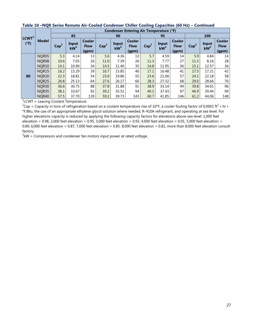
27
Table 10 –NQR Series Remote Air-Cooled Condenser Chiller Cooling Capacities (60 Hz) – Continued
LCWT1
(°F) Model
Condenser Entering Air Temperature (°F)
85 90 95 100
Cap2 Input
kW3
Cooler
Flow
(gpm)
Cap2 Input
kW3
Cooler
Flow
(gpm)
Cap2 Input
kW3
Cooler
Flow
(gpm)
Cap2 Input
kW3
Cooler
Flow
(gpm)
80
NQR05 5.3 4.14 13 5.6 4.36 13 5.7 4.59 14 5.9 4.84 14
NQR08 10.6 7.05 26 11.0 7.39 26 11.3 7.77 27 11.5 8.16 28
NQR10 14.1 10.90 34 14.5 11.40 35 14.8 11.95 36 15.1 12.57 36
NQR15 16.2 15.29 39 16.7 15.85 40 17.1 16.48 41 17.5 17.21 42
NQR20 22.3 18.81 54 23.0 19.86 55 23.6 21.00 57 24.1 22.18 58
NQR25 26.8 25.13 64 27.6 26.17 66 28.3 27.32 68 29.0 28.66 70
NQR30 36.6 30.75 88 37.8 31.88 91 38.9 33.14 94 39.8 34.61 96
NQR35 38.1 33.67 92 39.2 35.51 94 40.1 37.43 97 40.9 39.44 99
NQR40 57.5 37.70 139 59.2 39.73 143 60.7 41.85 146 61.2 44.06 148 1LCWT = Leaving Coolant Temperature.
2Cap = Capacity in tons of refrigeration based on a coolant temperature rise of 10°F, a cooler fouling factor of 0.0001 ft
2 • hr •
°F/Btu, the use of an appropriate ethylene glycol solution where needed, R-410A refrigerant, and operating at sea level. For
higher elevations capacity is reduced by applying the following capacity factors for elevations above sea level: 1,000 feet
elevation = 0.98, 2,000 feet elevation = 0.95, 3,000 feet elevation = 0.93, 4,000 feet elevation = 0.91, 5,000 feet elevation =
0.89, 6,000 feet elevation = 0.87, 7,000 feet elevation = 0.85. 8,000 feet elevation = 0.81, more than 8,000 feet elevation consult
factory. 3kW = Compressors and condenser fan motors input power at rated voltage.
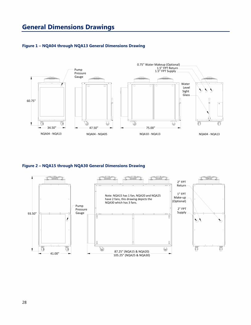
28
General Dimensions Drawings
Figure 1 – NQA04 through NQA13 General Dimensions Drawing
Figure 2 – NQA15 through NQA30 General Dimensions Drawing
75.00"
0.75" Water Makeup (Optional)
34.50"
60.75"
PumpPressureGauge
1.5" FPT Return
WaterLevel
SightGlass
1.5" FPT Supply
47.50"
NQA04 - NQA13 NQA04 - NQA05 NQA10 - NQA13 NQA04 - NQA13
PumpPressureGauge93.50"
41.00"
2" FPTReturn
1" FPTMake-up
(Optional)
2" FPTSupply
Note: NQA15 has 1 fan, NQA20 and NQA25 have 2 fans, this drawing depicts the NQA30 which has 3 fans.
87.25" (NQA15 & NQA20)105.25" (NQA25 & NQA30)
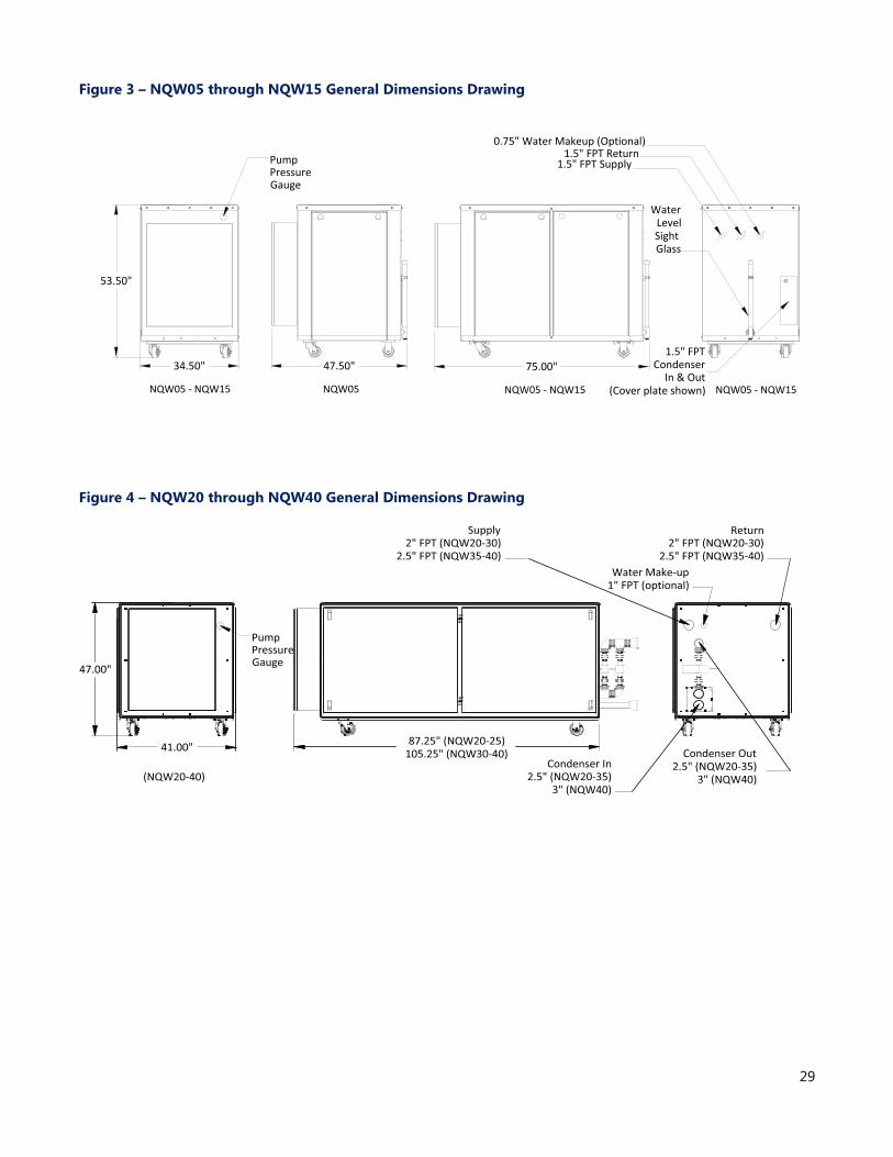
29
Figure 3 – NQW05 through NQW15 General Dimensions Drawing
Figure 4 – NQW20 through NQW40 General Dimensions Drawing
75.00"
0.75" Water Makeup (Optional)
53.50"
34.50"
PumpPressureGauge
WaterLevel
SightGlass
1.5" FPTCondenser
In & Out(Cover plate shown)
1.5" FPT Return1.5" FPT Supply
47.50"
NQW05 - NQW15 NQW05 NQW05 - NQW15 NQW05 - NQW15
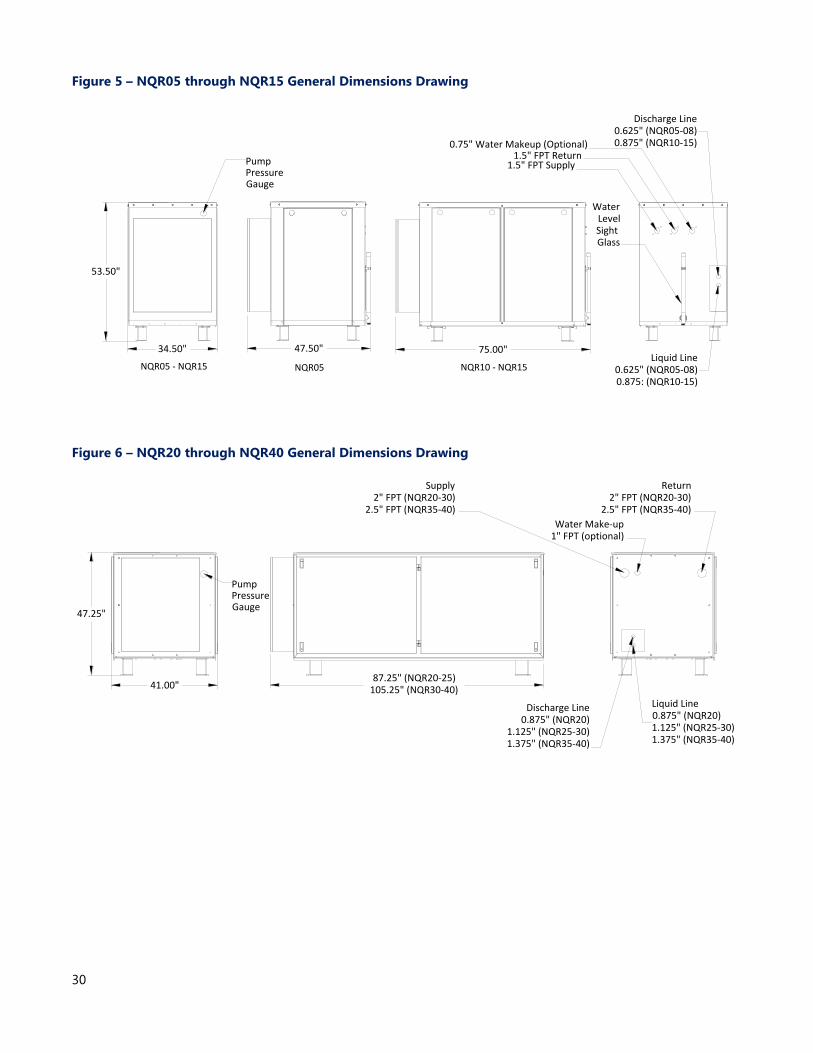
30
Figure 5 – NQR05 through NQR15 General Dimensions Drawing
Figure 6 – NQR20 through NQR40 General Dimensions Drawing
PumpPressureGauge
0.75" Water Makeup (Optional)
1.5" FPT Supply1.5" FPT Return
WaterLevel
SightGlass
Liquid Line0.625" (NQR05-08)0.875: (NQR10-15)
Discharge Line0.625" (NQR05-08)0.875" (NQR10-15)
47.50"
53.50"
34.50" 75.00"
NQR05 - NQR15 NQR05 NQR10 - NQR15
PumpPressureGauge
Liquid Line0.875" (NQR20)1.125" (NQR25-30)1.375" (NQR35-40)
Discharge Line0.875" (NQR20)
1.125" (NQR25-30)1.375" (NQR35-40)
47.25"
41.00"
Supply2" FPT (NQR20-30)
2.5" FPT (NQR35-40)
Water Make-up1" FPT (optional)
Return2" FPT (NQR20-30)
2.5" FPT (NQR35-40)
87.25" (NQR20-25)105.25" (NQR30-40)
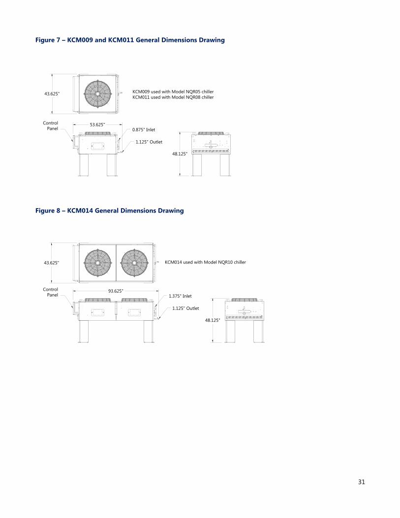
31
Figure 7 – KCM009 and KCM011 General Dimensions Drawing
Figure 8 – KCM014 General Dimensions Drawing
0.875" Inlet
1.125" Outlet
Control
Panel53.625"
48.125"
KCM009 used with Model NQR05 chiller
KCM011 used with Model NQR08 chiller43.625"
Control
Panel 1.375" Inlet
1.125" Outlet
48.125"
93.625"
KCM014 used with Model NQR10 chiller43.625"
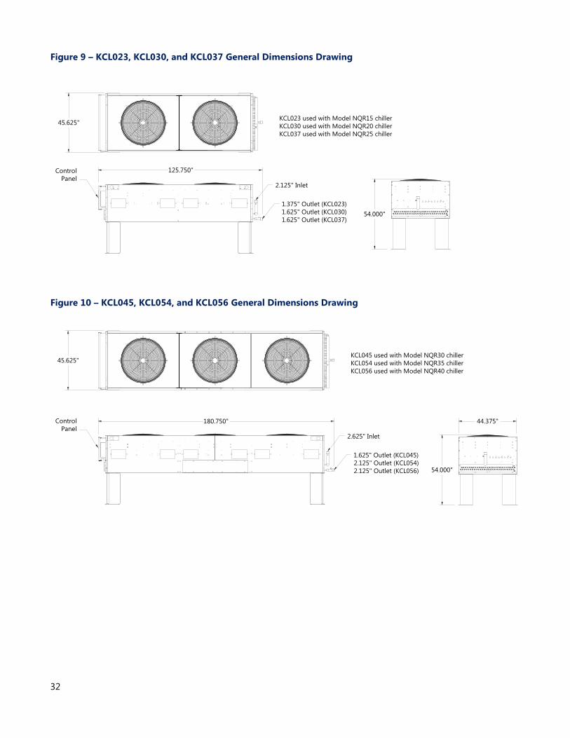
32
Figure 9 – KCL023, KCL030, and KCL037 General Dimensions Drawing
Figure 10 – KCL045, KCL054, and KCL056 General Dimensions Drawing
2.125" Inlet
1.375" Outlet (KCL023)
1.625" Outlet (KCL030)
1.625" Outlet (KCL037)
Control
Panel
125.750"
54.000"
KCL023 used with Model NQR15 chiller
KCL030 used with Model NQR20 chiller
KCL037 used with Model NQR25 chiller
45.625"
Control
Panel2.625" Inlet
1.625" Outlet (KCL045)
2.125" Outlet (KCL054)
2.125" Outlet (KCL056)
180.750"
54.000"
KCL045 used with Model NQR30 chiller
KCL054 used with Model NQR35 chiller
KCL056 used with Model NQR40 chiller
44.375"
45.625"
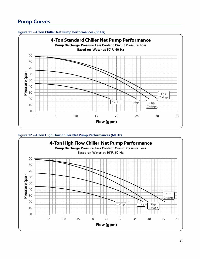
33
Pump Curves
Figure 11 – 4 Ton Chiller Net Pump Performances (60 Hz)
Figure 12 – 4 Ton High Flow Chiller Net Pump Performances (60 Hz)
0
10
20
30
40
50
60
70
80
90
0 5 10 15 20 25 30 35
Pre
ssu
re (
psi
)
Flow (gpm)
4-Ton Standard Chiller Net Pump PerformancePump Discharge Pressure Less Coolant Circuit Pressure Loss
Based on Water at 50°F, 60 Hz
1½ hp 3 hp 3 hp2-stage
5 hp
2-stage
0
10
20
30
40
50
60
70
80
90
0 5 10 15 20 25 30 35 40 45 50
Pre
ssu
re (
psi
)
Flow (gpm)
4-Ton High Flow Chiller Net Pump PerformancePump Discharge Pressure Less Coolant Circuit Pressure Loss
Based on Water at 50°F, 60 Hz
1½ hp 3 hp 3 hp
2-stage
5 hp
2-stage
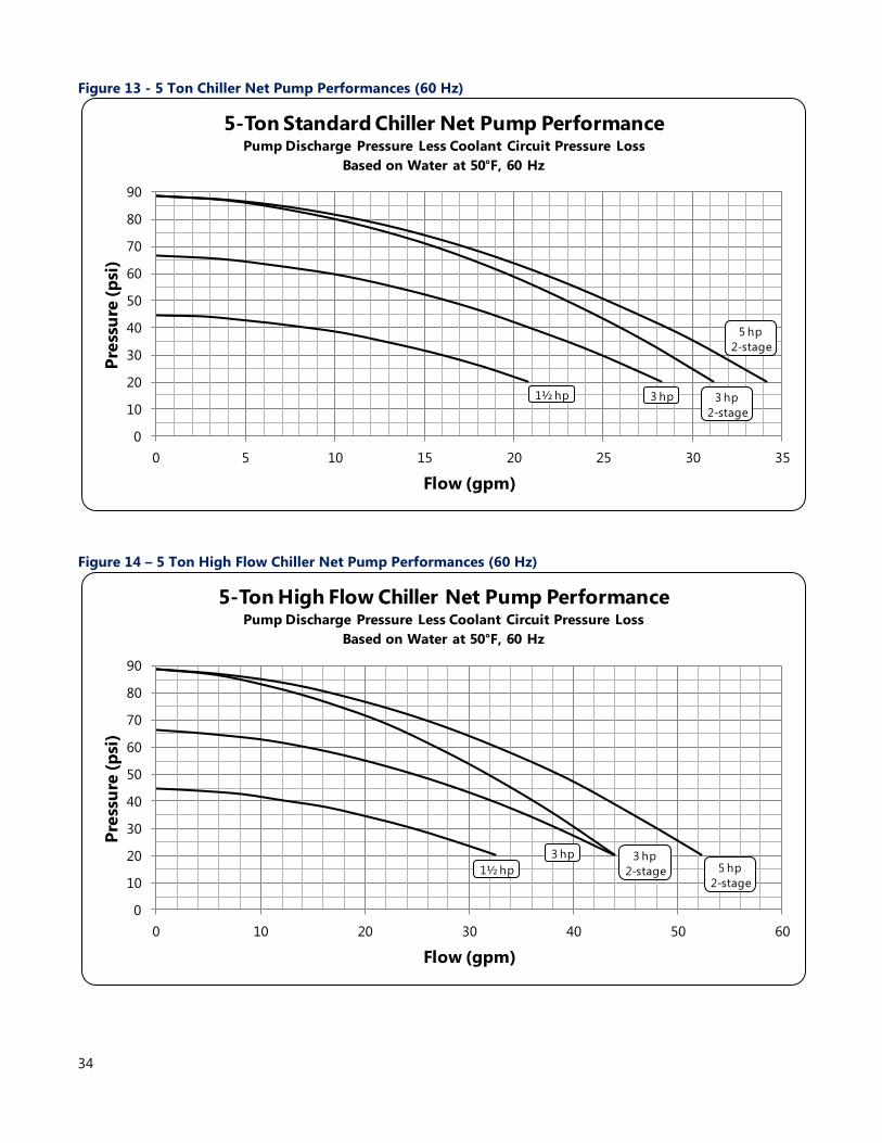
34
Figure 13 - 5 Ton Chiller Net Pump Performances (60 Hz)
Figure 14 – 5 Ton High Flow Chiller Net Pump Performances (60 Hz)
0
10
20
30
40
50
60
70
80
90
0 5 10 15 20 25 30 35
Pre
ssu
re (
psi
)
Flow (gpm)
5-Ton Standard Chiller Net Pump PerformancePump Discharge Pressure Less Coolant Circuit Pressure Loss
Based on Water at 50°F, 60 Hz
1½ hp 3 hp 3 hp
2-stage
5 hp
2-stage
0
10
20
30
40
50
60
70
80
90
0 10 20 30 40 50 60
Pre
ssu
re (
psi
)
Flow (gpm)
5-Ton High Flow Chiller Net Pump PerformancePump Discharge Pressure Less Coolant Circuit Pressure Loss
Based on Water at 50°F, 60 Hz
1½ hp
3 hp 3 hp
2-stage 5 hp
2-stage
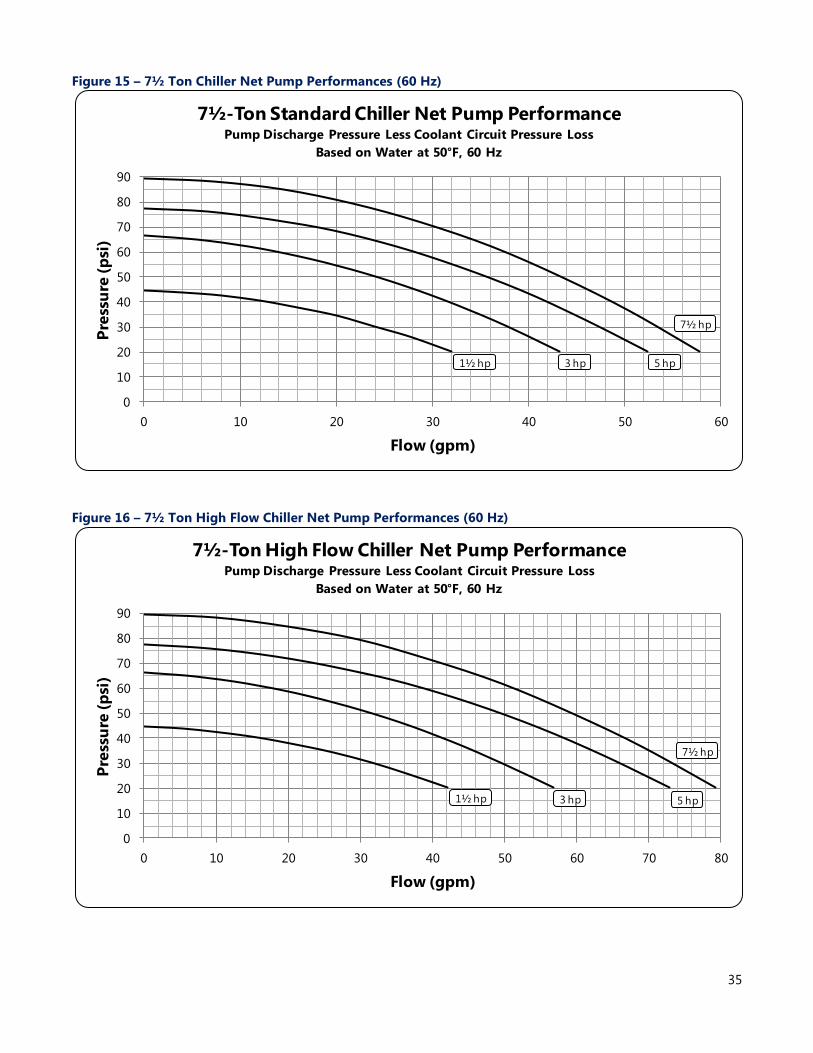
35
Figure 15 – 7½ Ton Chiller Net Pump Performances (60 Hz)
Figure 16 – 7½ Ton High Flow Chiller Net Pump Performances (60 Hz)
0
10
20
30
40
50
60
70
80
90
0 10 20 30 40 50 60
Pre
ssu
re (
psi
)
Flow (gpm)
7½-Ton Standard Chiller Net Pump PerformancePump Discharge Pressure Less Coolant Circuit Pressure Loss
Based on Water at 50°F, 60 Hz
1½ hp 3 hp
7½ hp
5 hp
0
10
20
30
40
50
60
70
80
90
0 10 20 30 40 50 60 70 80
Pre
ssu
re (
psi
)
Flow (gpm)
7½-Ton High Flow Chiller Net Pump PerformancePump Discharge Pressure Less Coolant Circuit Pressure Loss
Based on Water at 50°F, 60 Hz
1½ hp 3 hp 5 hp
7½ hp
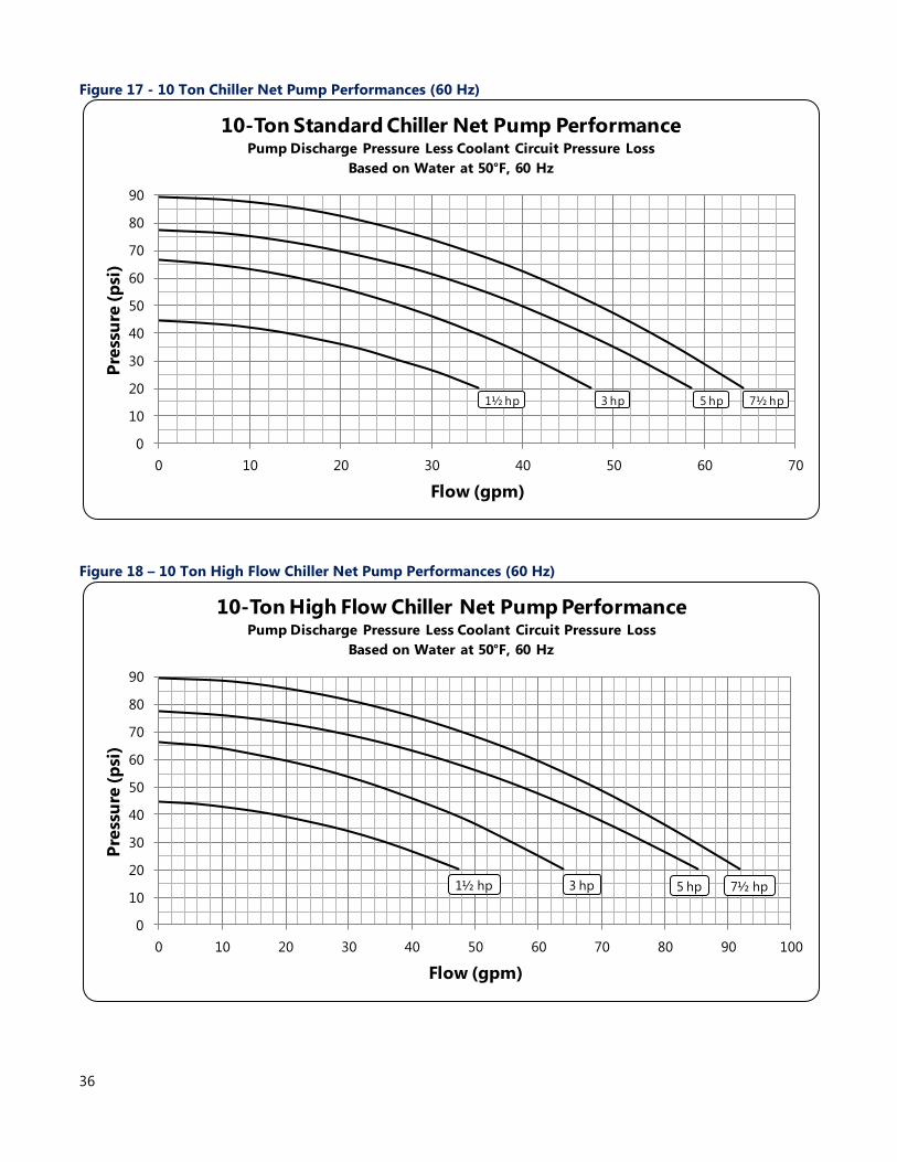
36
Figure 17 - 10 Ton Chiller Net Pump Performances (60 Hz)
Figure 18 – 10 Ton High Flow Chiller Net Pump Performances (60 Hz)
0
10
20
30
40
50
60
70
80
90
0 10 20 30 40 50 60 70
Pre
ssu
re (
psi
)
Flow (gpm)
10-Ton Standard Chiller Net Pump PerformancePump Discharge Pressure Less Coolant Circuit Pressure Loss
Based on Water at 50°F, 60 Hz
1½ hp 3 hp 7½ hp5 hp
0
10
20
30
40
50
60
70
80
90
0 10 20 30 40 50 60 70 80 90 100
Pre
ssu
re (
psi
)
Flow (gpm)
10-Ton High Flow Chiller Net Pump PerformancePump Discharge Pressure Less Coolant Circuit Pressure Loss
Based on Water at 50°F, 60 Hz
1½ hp 3 hp 7½ hp5 hp
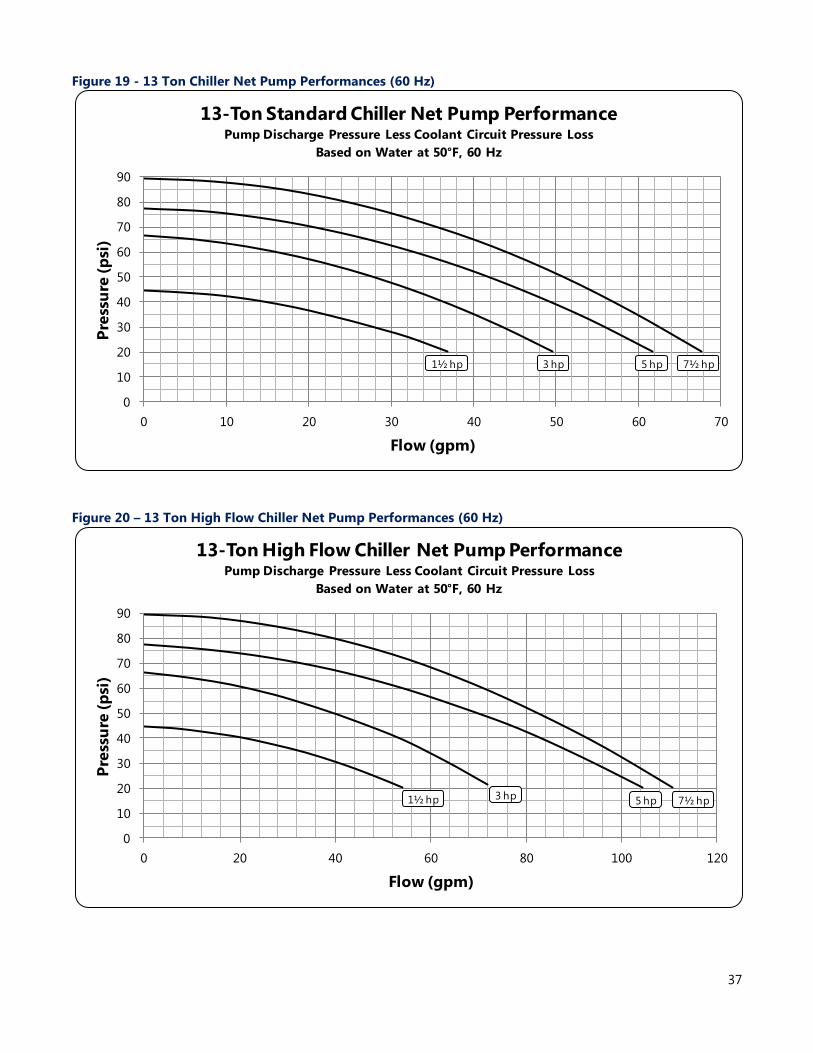
37
Figure 19 - 13 Ton Chiller Net Pump Performances (60 Hz)
Figure 20 – 13 Ton High Flow Chiller Net Pump Performances (60 Hz)
0
10
20
30
40
50
60
70
80
90
0 10 20 30 40 50 60 70
Pre
ssu
re (
psi
)
Flow (gpm)
13-Ton Standard Chiller Net Pump PerformancePump Discharge Pressure Less Coolant Circuit Pressure Loss
Based on Water at 50°F, 60 Hz
1½ hp 3 hp 7½ hp5 hp
0
10
20
30
40
50
60
70
80
90
0 20 40 60 80 100 120
Pre
ssu
re (
psi
)
Flow (gpm)
13-Ton High Flow Chiller Net Pump PerformancePump Discharge Pressure Less Coolant Circuit Pressure Loss
Based on Water at 50°F, 60 Hz
1½ hp 3 hp 7½ hp5 hp
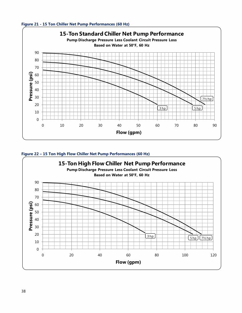
38
Figure 21 - 15 Ton Chiller Net Pump Performances (60 Hz)
Figure 22 – 15 Ton High Flow Chiller Net Pump Performances (60 Hz)
0
10
20
30
40
50
60
70
80
90
0 10 20 30 40 50 60 70 80 90
Pre
ssu
re (
psi
)
Flow (gpm)
15-Ton Standard Chiller Net Pump PerformancePump Discharge Pressure Less Coolant Circuit Pressure Loss
Based on Water at 50°F, 60 Hz
3 hp
7½ hp
5 hp
0
10
20
30
40
50
60
70
80
90
0 20 40 60 80 100 120
Pre
ssu
re (
psi
)
Flow (gpm)
15-Ton High Flow Chiller Net Pump PerformancePump Discharge Pressure Less Coolant Circuit Pressure Loss
Based on Water at 50°F, 60 Hz
3 hp7½ hp5 hp
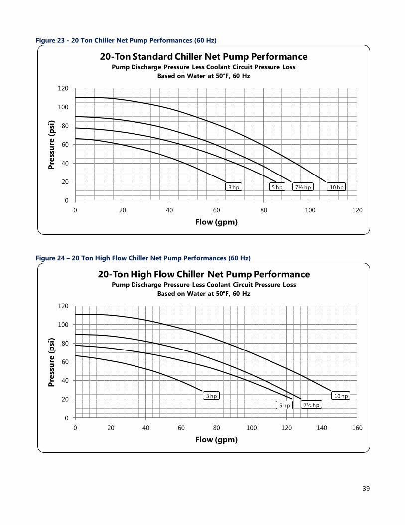
39
Figure 23 - 20 Ton Chiller Net Pump Performances (60 Hz)
Figure 24 – 20 Ton High Flow Chiller Net Pump Performances (60 Hz)
0
20
40
60
80
100
120
0 20 40 60 80 100 120
Pre
ssu
re (
psi
)
Flow (gpm)
20-Ton Standard Chiller Net Pump PerformancePump Discharge Pressure Less Coolant Circuit Pressure Loss
Based on Water at 50°F, 60 Hz
3 hp 7½ hp5 hp 10 hp
0
20
40
60
80
100
120
0 20 40 60 80 100 120 140 160
Pre
ssu
re (
psi
)
Flow (gpm)
20-Ton High Flow Chiller Net Pump PerformancePump Discharge Pressure Less Coolant Circuit Pressure Loss
Based on Water at 50°F, 60 Hz
3 hp
7½ hp5 hp
10 hp
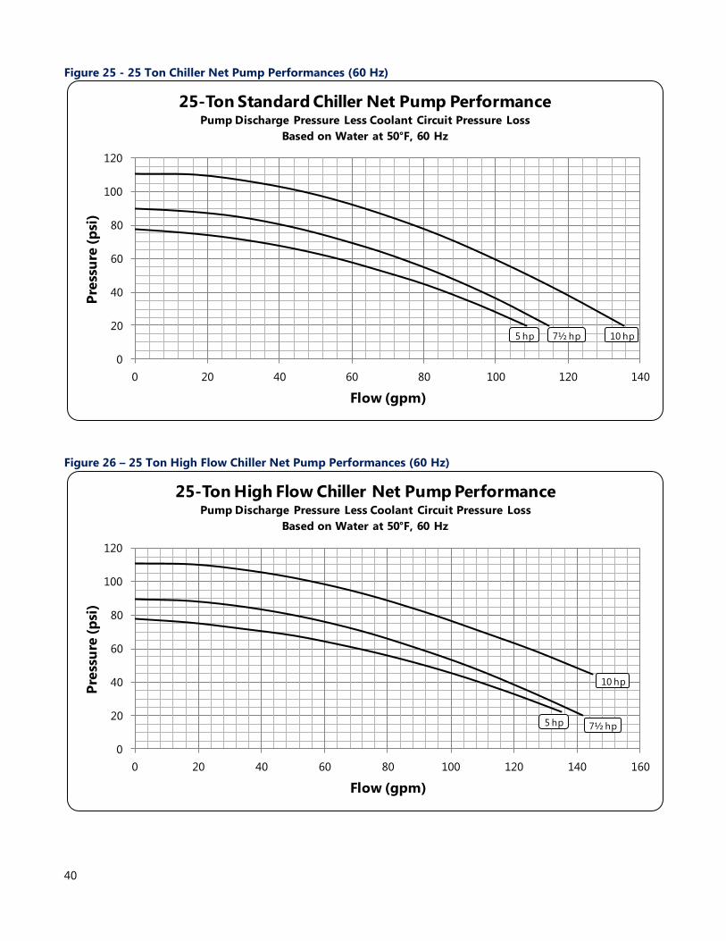
40
Figure 25 - 25 Ton Chiller Net Pump Performances (60 Hz)
Figure 26 – 25 Ton High Flow Chiller Net Pump Performances (60 Hz)
0
20
40
60
80
100
120
0 20 40 60 80 100 120 140
Pre
ssu
re (
psi
)
Flow (gpm)
25-Ton Standard Chiller Net Pump PerformancePump Discharge Pressure Less Coolant Circuit Pressure Loss
Based on Water at 50°F, 60 Hz
7½ hp5 hp 10 hp
0
20
40
60
80
100
120
0 20 40 60 80 100 120 140 160
Pre
ssu
re (
psi
)
Flow (gpm)
25-Ton High Flow Chiller Net Pump PerformancePump Discharge Pressure Less Coolant Circuit Pressure Loss
Based on Water at 50°F, 60 Hz
7½ hp5 hp
10 hp
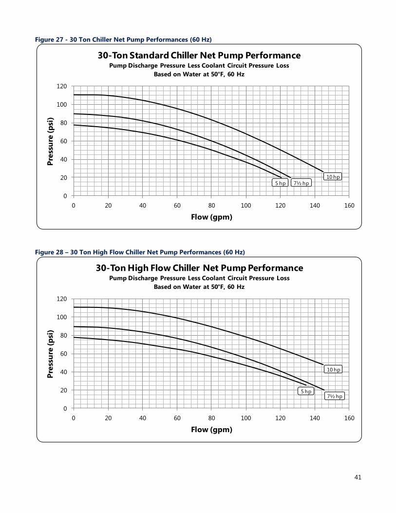
41
Figure 27 - 30 Ton Chiller Net Pump Performances (60 Hz)
Figure 28 – 30 Ton High Flow Chiller Net Pump Performances (60 Hz)
0
20
40
60
80
100
120
0 20 40 60 80 100 120 140 160
Pre
ssu
re (
psi
)
Flow (gpm)
30-Ton Standard Chiller Net Pump PerformancePump Discharge Pressure Less Coolant Circuit Pressure Loss
Based on Water at 50°F, 60 Hz
7½ hp5 hp
10 hp
0
20
40
60
80
100
120
0 20 40 60 80 100 120 140 160
Pre
ssu
re (
psi
)
Flow (gpm)
30-Ton High Flow Chiller Net Pump PerformancePump Discharge Pressure Less Coolant Circuit Pressure Loss
Based on Water at 50°F, 60 Hz
7½ hp5 hp
10 hp
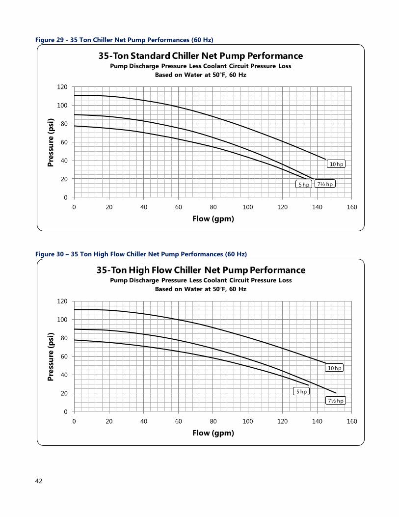
42
Figure 29 - 35 Ton Chiller Net Pump Performances (60 Hz)
Figure 30 – 35 Ton High Flow Chiller Net Pump Performances (60 Hz)
0
20
40
60
80
100
120
0 20 40 60 80 100 120 140 160
Pre
ssu
re (
psi
)
Flow (gpm)
35-Ton Standard Chiller Net Pump PerformancePump Discharge Pressure Less Coolant Circuit Pressure Loss
Based on Water at 50°F, 60 Hz
7½ hp5 hp
10 hp
0
20
40
60
80
100
120
0 20 40 60 80 100 120 140 160
Pre
ssu
re (
psi
)
Flow (gpm)
35-Ton High Flow Chiller Net Pump PerformancePump Discharge Pressure Less Coolant Circuit Pressure Loss
Based on Water at 50°F, 60 Hz
7½ hp
5 hp
10 hp
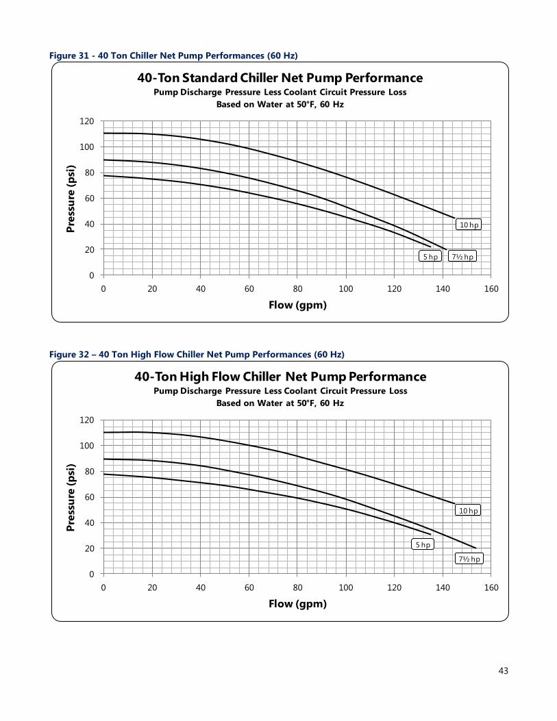
43
Figure 31 - 40 Ton Chiller Net Pump Performances (60 Hz)
Figure 32 – 40 Ton High Flow Chiller Net Pump Performances (60 Hz)
0
20
40
60
80
100
120
0 20 40 60 80 100 120 140 160
Pre
ssu
re (
psi
)
Flow (gpm)
40-Ton Standard Chiller Net Pump PerformancePump Discharge Pressure Less Coolant Circuit Pressure Loss
Based on Water at 50°F, 60 Hz
7½ hp5 hp
10 hp
0
20
40
60
80
100
120
0 20 40 60 80 100 120 140 160
Pre
ssu
re (
psi
)
Flow (gpm)
40-Ton High Flow Chiller Net Pump PerformancePump Discharge Pressure Less Coolant Circuit Pressure Loss
Based on Water at 50°F, 60 Hz
7½ hp
5 hp
10 hp
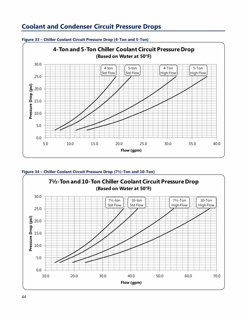
44
Coolant and Condenser Circuit Pressure Drops
Figure 33 – Chiller Coolant Circuit Pressure Drop (4-Ton and 5-Ton)
Figure 34 – Chiller Coolant Circuit Pressure Drop (7½-Ton and 10-Ton)
0.0
5.0
10.0
15.0
20.0
25.0
30.0
5.0 10.0 15.0 20.0 25.0 30.0 35.0 40.0
Pre
ssu
re D
rop
(p
si)
Flow (gpm)
4-Ton and 5-Ton Chiller Coolant Circuit Pressure Drop(Based on Water at 50°F)
4-ton
Std Flow
5-ton
Std Flow
4-Ton
High Flow
5-Ton
High Flow
0.0
5.0
10.0
15.0
20.0
25.0
30.0
10.0 20.0 30.0 40.0 50.0 60.0 70.0
Pre
ssu
re D
rop
(p
si)
Flow (gpm)
7½-Ton and 10-Ton Chiller Coolant Circuit Pressure Drop(Based on Water at 50°F)
7½-ton
Std Flow
10-ton
Std Flow
7½-Ton
High Flow
10-Ton
High Flow
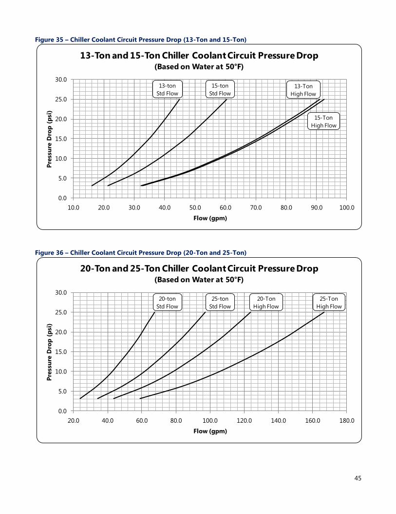
45
Figure 35 – Chiller Coolant Circuit Pressure Drop (13-Ton and 15-Ton)
Figure 36 – Chiller Coolant Circuit Pressure Drop (20-Ton and 25-Ton)
0.0
5.0
10.0
15.0
20.0
25.0
30.0
10.0 20.0 30.0 40.0 50.0 60.0 70.0 80.0 90.0 100.0
Pre
ssu
re D
rop
(p
si)
Flow (gpm)
13-Ton and 15-Ton Chiller Coolant Circuit Pressure Drop(Based on Water at 50°F)
13-ton
Std Flow
15-ton
Std Flow
13-Ton
High Flow
15-Ton
High Flow
0.0
5.0
10.0
15.0
20.0
25.0
30.0
20.0 40.0 60.0 80.0 100.0 120.0 140.0 160.0 180.0
Pre
ssu
re D
rop
(p
si)
Flow (gpm)
20-Ton and 25-Ton Chiller Coolant Circuit Pressure Drop(Based on Water at 50°F)
20-ton
Std Flow
25-ton
Std Flow
20-Ton
High Flow
25-Ton
High Flow
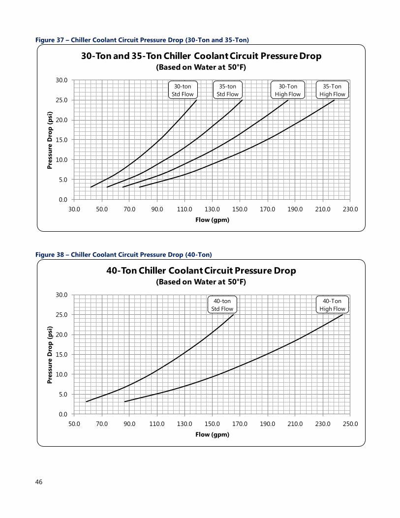
46
Figure 37 – Chiller Coolant Circuit Pressure Drop (30-Ton and 35-Ton)
Figure 38 – Chiller Coolant Circuit Pressure Drop (40-Ton)
0.0
5.0
10.0
15.0
20.0
25.0
30.0
30.0 50.0 70.0 90.0 110.0 130.0 150.0 170.0 190.0 210.0 230.0
Pre
ssu
re D
rop
(p
si)
Flow (gpm)
30-Ton and 35-Ton Chiller Coolant Circuit Pressure Drop(Based on Water at 50°F)
30-ton
Std Flow
35-ton
Std Flow
30-Ton
High Flow
35-Ton
High Flow
0.0
5.0
10.0
15.0
20.0
25.0
30.0
50.0 70.0 90.0 110.0 130.0 150.0 170.0 190.0 210.0 230.0 250.0
Pre
ssu
re D
rop
(p
si)
Flow (gpm)
40-Ton Chiller Coolant Circuit Pressure Drop(Based on Water at 50°F)
40-ton
Std Flow
40-Ton
High Flow
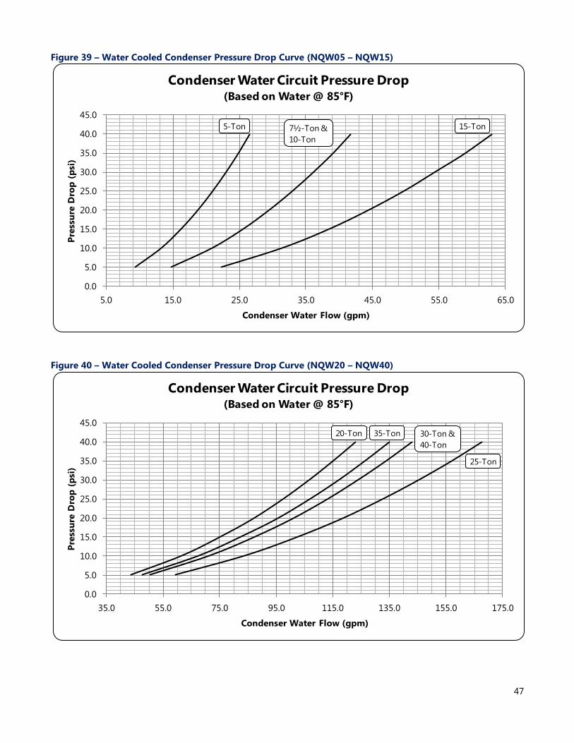
47
Figure 39 – Water Cooled Condenser Pressure Drop Curve (NQW05 – NQW15)
Figure 40 – Water Cooled Condenser Pressure Drop Curve (NQW20 – NQW40)
0.0
5.0
10.0
15.0
20.0
25.0
30.0
35.0
40.0
45.0
5.0 15.0 25.0 35.0 45.0 55.0 65.0
Pre
ssu
re D
rop
(p
si)
Condenser Water Flow (gpm)
Condenser Water Circuit Pressure Drop(Based on Water @ 85°F)
5-Ton 7½-Ton &
10-Ton
15-Ton
0.0
5.0
10.0
15.0
20.0
25.0
30.0
35.0
40.0
45.0
35.0 55.0 75.0 95.0 115.0 135.0 155.0 175.0
Pre
ssu
re D
rop
(p
si)
Condenser Water Flow (gpm)
Condenser Water Circuit Pressure Drop(Based on Water @ 85°F)
20-Ton 35-Ton 30-Ton &
40-Ton
25-Ton
48
Application Considerations The following section describes various application
topics that are important for many industrial cooling
system designs. As is the case with all chilled water
system designs, we recommend care be taken to
ensure all aspects of the system are considered and
all extreme operating conditions accounted for. If
your application is out the application considerations
shown in this section, contact your local sales
representative for assistance.
Unit Sizing The Performance Data of this product catalog shows
the chiller performances at select conditions that
cover the majority of design conditions common in
industrial chiller applications. If your design
conditions fall between the points shown
interpolation is allowed; however extrapolation is
not.
Over-sizing chillers is sometimes necessary to allow
for future growth. While this practice may be
necessary, it is highly recommended chillers be sized
for continuous operation at 30% load or more to
avoid unwanted reductions in system efficiency,
excessive electrical power use, and compressor
cycling due to reduced chiller loading.
Unit Location All standard chillers are designed for indoor
installation with 60°F and 110°F ambient air. Chillers
with an integral air-cooled condenser and the
outdoor-duty construction option may be located
outdoors in areas with -20°F and 110°F ambient air.
Chillers with a remote air-cooled condenser are
designed to have the chiller located indoors in an
area with 60°F and 110°F ambient air and the remote
condenser outdoors in an area with -20°F and 110°F
ambient air. For remote air-cooled condensers allow
a minimum of 48 inches between the condenser and
any walls or obstructions. For installations with
multiple remote air-cooled condensers, allow a
minimum of 96 inches between condensers placed
side-by-side or 48 inches for condensers placed end-
to-end. In all cases install the equipment on a rigid
surface suitable to support the full operating weight
of the unit. Level all equipment to ensure proper
operation. See the NQ Series manual for installation
guidelines for designing the interconnecting
refrigeration piping as well as estimating the
required refrigerant charge for the system.
Serviceability was an important factor in the design
of our equipment. Do not compromise this feature
by locating the chiller in an inaccessible area. When
locating the chiller it is important to consider
accessibility to the components to allow for proper
maintenance and servicing of the unit. In general,
allow a minimum of 36 inches of clearance around
all sides and above the unit. Avoid locating piping or
conduit over the unit. This ensures easy access with
an overhead crane or lift to lift out heavier
components when they are replaced or serviced.
Proper ventilation is another important
consideration when locating the unit. Locate the unit
in an area that will not rise above 110°F. In addition,
ensure the condenser and evaporator refrigerant
pressure relief valves can vent in accordance with all
local and national codes.
Chillers with an integral air-cooled condenser require
a minimum of 36 inches of clearance at both the
condenser air inlet and condenser air discharge.
They are not designed to have the condenser air
discharge ducted. Improper clearance or poor
ventilation will reduce the cooling capacity of the
chiller and may cause high refrigerant pressure
problems. In order to avoid possible low refrigerant
pressure safety trips during start-up, maintain the
inlet air temperature above 60°F. If outside air is
ducted into an indoor chiller with an integral air-
cooled condenser there is an option for low ambient
heat pressure controls which allow for incoming air
temperatures down to 0°F.
Process Fluid Temperature The chiller can operate with a variety of different
supply and return temperatures. The standard
operating range for the process fluid is 20°F to 80°F
with a minimum entering coolant temperature of
22.5°F. The chiller can handle an initial pull down of a
reservoir or process fluid loop on start-up up to 95°F
entering fluid temperature. Under normal
continuous operation, we recommend the entering
water temperature not exceed 90°F.
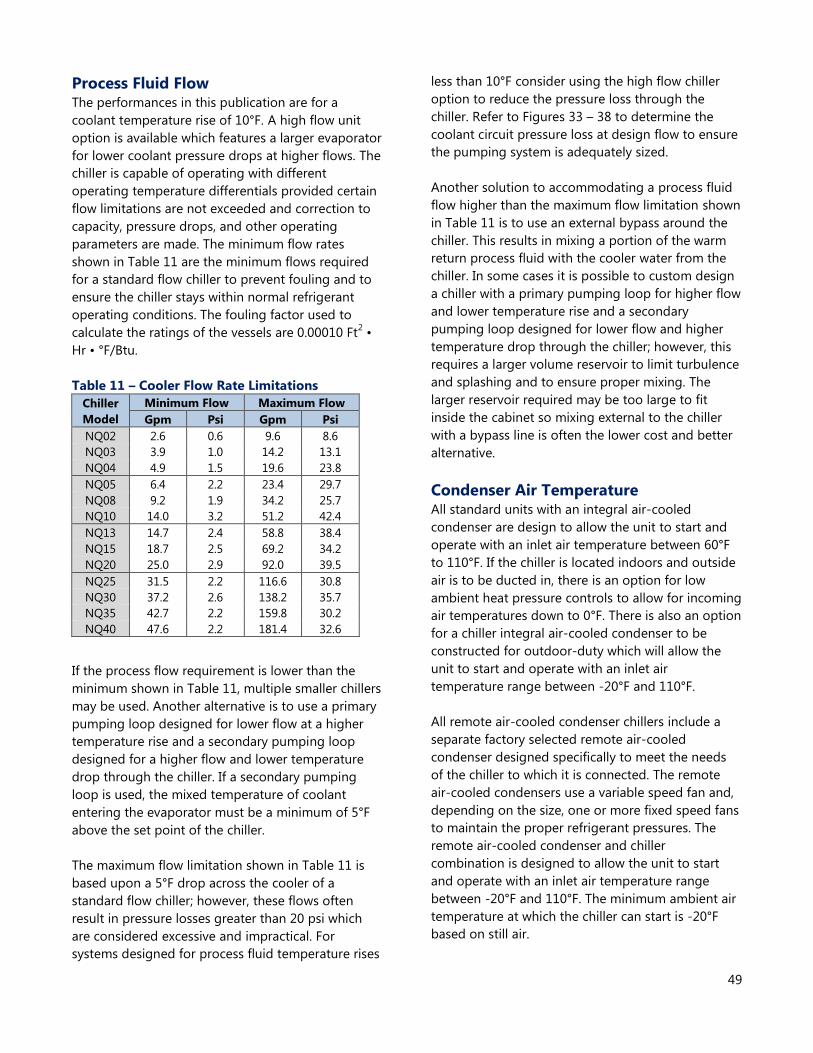
49
Process Fluid Flow The performances in this publication are for a
coolant temperature rise of 10°F. A high flow unit
option is available which features a larger evaporator
for lower coolant pressure drops at higher flows. The
chiller is capable of operating with different
operating temperature differentials provided certain
flow limitations are not exceeded and correction to
capacity, pressure drops, and other operating
parameters are made. The minimum flow rates
shown in Table 11 are the minimum flows required
for a standard flow chiller to prevent fouling and to
ensure the chiller stays within normal refrigerant
operating conditions. The fouling factor used to
calculate the ratings of the vessels are 0.00010 Ft2 •
Hr • °F/Btu.
Table 11 – Cooler Flow Rate Limitations
If the process flow requirement is lower than the
minimum shown in Table 11, multiple smaller chillers
may be used. Another alternative is to use a primary
pumping loop designed for lower flow at a higher
temperature rise and a secondary pumping loop
designed for a higher flow and lower temperature
drop through the chiller. If a secondary pumping
loop is used, the mixed temperature of coolant
entering the evaporator must be a minimum of 5°F
above the set point of the chiller.
The maximum flow limitation shown in Table 11 is
based upon a 5°F drop across the cooler of a
standard flow chiller; however, these flows often
result in pressure losses greater than 20 psi which
are considered excessive and impractical. For
systems designed for process fluid temperature rises
less than 10°F consider using the high flow chiller
option to reduce the pressure loss through the
chiller. Refer to Figures 33 – 38 to determine the
coolant circuit pressure loss at design flow to ensure
the pumping system is adequately sized.
Another solution to accommodating a process fluid
flow higher than the maximum flow limitation shown
in Table 11 is to use an external bypass around the
chiller. This results in mixing a portion of the warm
return process fluid with the cooler water from the
chiller. In some cases it is possible to custom design
a chiller with a primary pumping loop for higher flow
and lower temperature rise and a secondary
pumping loop designed for lower flow and higher
temperature drop through the chiller; however, this
requires a larger volume reservoir to limit turbulence
and splashing and to ensure proper mixing. The
larger reservoir required may be too large to fit
inside the cabinet so mixing external to the chiller
with a bypass line is often the lower cost and better
alternative.
Condenser Air Temperature All standard units with an integral air-cooled
condenser are design to allow the unit to start and
operate with an inlet air temperature between 60°F
to 110°F. If the chiller is located indoors and outside
air is to be ducted in, there is an option for low
ambient heat pressure controls to allow for incoming
air temperatures down to 0°F. There is also an option
for a chiller integral air-cooled condenser to be
constructed for outdoor-duty which will allow the
unit to start and operate with an inlet air
temperature range between -20°F and 110°F.
All remote air-cooled condenser chillers include a
separate factory selected remote air-cooled
condenser designed specifically to meet the needs
of the chiller to which it is connected. The remote
air-cooled condensers use a variable speed fan and,
depending on the size, one or more fixed speed fans
to maintain the proper refrigerant pressures. The
remote air-cooled condenser and chiller
combination is designed to allow the unit to start
and operate with an inlet air temperature range
between -20°F and 110°F. The minimum ambient air
temperature at which the chiller can start is -20°F
based on still air.
Chiller
Model
Minimum Flow Maximum Flow
Gpm Psi Gpm Psi
NQ02 2.6 0.6 9.6 8.6
NQ03 3.9 1.0 14.2 13.1
NQ04 4.9 1.5 19.6 23.8
NQ05 6.4 2.2 23.4 29.7
NQ08 9.2 1.9 34.2 25.7
NQ10 14.0 3.2 51.2 42.4
NQ13 14.7 2.4 58.8 38.4
NQ15 18.7 2.5 69.2 34.2
NQ20 25.0 2.9 92.0 39.5
NQ25 31.5 2.2 116.6 30.8
NQ30 37.2 2.6 138.2 35.7
NQ35 42.7 2.2 159.8 30.2
NQ40 47.6 2.2 181.4 32.6
50
For certain high ambient areas such as desert
locations, there is an option for a high-ambient
package. This includes changing the refrigerant from
R410A to R407c as well as the associated
refrigeration component changes required to use
the different refrigerant. With this option the chiller
is able to operate with ambient temperatures up to
122°F. Careful consideration must be taken in
locations typical of such high ambient conditions.
Consult your local sales representative for assistance
with applications that require higher than 110°F
ambient air operation.
System Fluid Freeze Protection For applications where the system fluid is exposed to
ambient conditions of 32°F or colder and/or the set
point of the system is below 45°F, antifreeze must be
added to the system fluid to protect the chiller and
system piping from potential damage. The amount
of antifreeze varies depending on the actual desired
operating conditions and must be enough to
provide freeze protection to temperatures 15°F
colder than the coldest temperature anticipated. Use
only antifreeze solutions designed for heat
exchanger duty. Do not use automotive antifreeze
because there is a potential for fouling that can
occur once its relatively short-lived inhibitors break
down.
Strainers Each evaporator has a 20-mesh inlet strainer to
protect the evaporator. For units with water-cooled
condensers, we recommend a filtration system
capable of filtering down to a minimum of 20 mesh
to protect the condenser from contamination.

Notes

7720 North Lehigh Avenue
Niles, Illinois 60714-3491
Tel: (847) 966-2260
Toll Free: (888) 828-7387
Fax: (847) 966-9358
Email: [email protected]
Website: www.thermalcare.com
Manufacturer reserves the
right to change specifications
or design without notice or
obligation.
NQ Series Product Catalog (2-232.19)
January 2015