Embed Size (px)
Citation preview
MULTI-SENSOR FUSION FOR AUTOMATED GUIDED VEHICLE
POSITIONING
SAID ABDO AHMED ELSHAYEB
A Thesis submitted in
fulfillment of the requirement for the award of the
Degree of Master of Mechanical Engineering
Faculty of Mechanical and Manufacturing Engineering
Universiti Tun Hussein Onn Malaysia
JULY 2010
ii
I hereby declare that the work in this project report is my own except for quotations
and summaries, which have been duly acknowledged
Student : SAID ABDO AHMED ELSHAYEB
Date : JULY 2010
Supervisor : ASSOC. PROF. DR. KHALID HASNAN
Co supervisor : PROF. IR. DR. SAPARUDDIN ARIFFIN

iii
For my beloved mother, Huda
And my brother, Ahmed Elshayeb

iv
ACKNOWLEDGEMENT
Primarily I would like to thank the almighty God (ALLAH) for blessing me and
guiding me through all the stages of my life, up to this point. Without this guidance,
I would have never reached the position where I am writing this page.
Straight second to that I would like to express my deep gratitude, honor, and
admiration to my supervisor Assoc. Prof. Dr. Khalid Bin Hasnan. I cannot ever say
enough to adequately express my appreciation to him for being a supervisor of a
prestige class made of him alone a class beyond extreme excellence. With such
richness in knowledge, experience and dedication, he provided the right vision and
direction which led to the completion of this work; always prepared to help, always
having time to listen and always open to discussion.
A great appreciation is also due to Prof. Dr. Saparuddin Ariffin, who has
repeatedly given me some of his precious time for technical discussion and advice. I
would also like to express my thanks to my colleagues and friends in the department
at UTHM who contributed to this work through either individual or group
discussions.
v
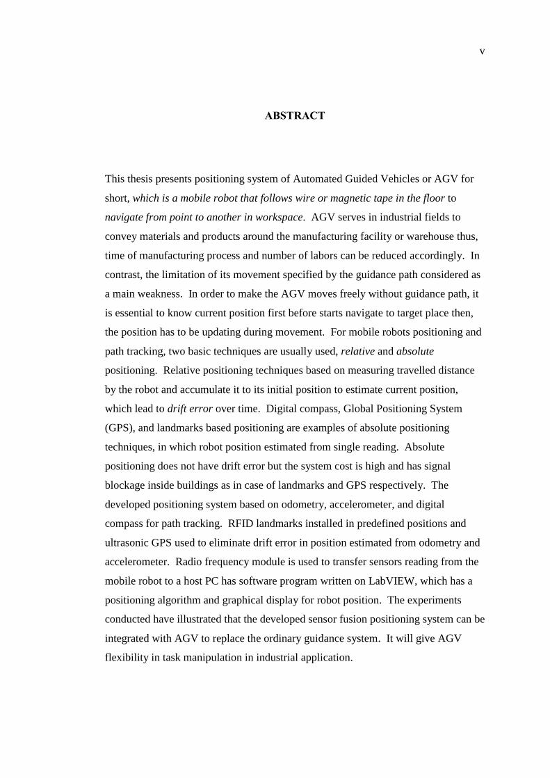
ABSTRACT
This thesis presents positioning system of Automated Guided Vehicles or AGV for
short, which is a mobile robot that follows wire or magnetic tape in the floor to
navigate from point to another in workspace. AGV serves in industrial fields to
convey materials and products around the manufacturing facility or warehouse thus,
time of manufacturing process and number of labors can be reduced accordingly. In
contrast, the limitation of its movement specified by the guidance path considered as
a main weakness. In order to make the AGV moves freely without guidance path, it
is essential to know current position first before starts navigate to target place then,
the position has to be updating during movement. For mobile robots positioning and
path tracking, two basic techniques are usually used, relative and absolute
positioning. Relative positioning techniques based on measuring travelled distance
by the robot and accumulate it to its initial position to estimate current position,
which lead to drift error over time. Digital compass, Global Positioning System
(GPS), and landmarks based positioning are examples of absolute positioning
techniques, in which robot position estimated from single reading. Absolute
positioning does not have drift error but the system cost is high and has signal
blockage inside buildings as in case of landmarks and GPS respectively. The
developed positioning system based on odometry, accelerometer, and digital
compass for path tracking. RFID landmarks installed in predefined positions and
ultrasonic GPS used to eliminate drift error in position estimated from odometry and
accelerometer. Radio frequency module is used to transfer sensors reading from the
mobile robot to a host PC has software program written on LabVIEW, which has a
positioning algorithm and graphical display for robot position. The experiments
conducted have illustrated that the developed sensor fusion positioning system can be
integrated with AGV to replace the ordinary guidance system. It will give AGV
flexibility in task manipulation in industrial application.
vi
CONTENTS
MULTI-SENSOR FUSION FOR AUTOMATED GUIDED VEHICLE
POSITIONING i
ACKNOWLEDGEMENT iv
ABSTRACT v
CONTENTS vi
LIST OF TABLES xi
LIST OF FIGURES xii
LIST OF APPENDICES xiv
CHAPTER 1 INTRODUCTION 1
1.1 Mobile robots 1
1.1.1 Mobility 2
vii
1.1.2 Autonomy 2
1.2 Automated guided vehicle (AGV) 3
1.3 Problem statement 5
1.4 Research objectives 6
1.5 Scopes of the research 6
1.6 Summary 7
CHAPTER 2 LITERATURE REVIEW 8
2.1 Relative positioning techniques 8
2.1.1 Odometry 9
2.1.2 Accelerometer 10
2.2 Absolute positioning techniques 11
2.2.1 Magnetic compass 12
viii
2.2.2 Landmarks based positioning 14
2.3 Global positioning system (GPS) 15
2.4 Ultrasonic indoor GPS 17
2.5 Radio Frequency IDentification (RFID) 19
2.5.1 Types of RFID tags 20
2.5.2 RFID frequency bands 22
2.5.3 RFID for mobile robots positioning 23
2.6 Summary 24
CHAPTER 3 RESEARCH METHODOLOGY 26
3.1 Overview 26
3.2 Positioning algorithm 28
3.2.1 Indoor ultrasonic GPS system 32
ix
3.2.2 Positioning using RFID landmarks 34
3.3 Summary 35
CHAPTER 4 EXPERIMENTAL RESULTS 36
4.1 Positioning system layout 36
4.2 Positioning module electronic board 38
4.2.1 Interface RFID reader with microcontroller 39
4.2.2 Digital compass programming and interface circuit 40
4.2.3 Accelerometer programming and interface circuit 42
4.2.4 Wireless radio module setting and programming 43
4.3 Developed graphical user interface on host PC and PDA 48
4.3.1 Serial port setting in the PC side 49
4.3.2 Insert RFID tags number into the database 49
x
4.3.3 Robot control setting in term of robot speed and initial position 50
4.3.4 Setting up Wi-Fi communication between the PC and PDA 51
4.4 Experimental results 52
4.4.1 Digital compass startup setting 53
4.4.2 Ultrasonic GPS electic circuit and experimental results 56
4.4.3 RFID landmarks for position correction 60
4.5 Summary 63
Chapter 5 CONCLUSION AND FUTURE WORK 64
REFERENCES 66
APPENDICES 73
xi
LIST OF TABLES
4.1: RFID reader connection specification with Microcontroller 40
4.2: Xbee wireless module specifications 44
4.3: Some commonly used commands in AT mode 47
xii
LIST OF FIGURES
1.1: TAW type AGV (HI-Tech Robotics Systemz LTD) 4
2.1: Compass used in orienteering (Kjernsmo, 2003) 12
2.2: Global Positioning System 16
3.1: Research methodology flow chart 27
3.2: Layout of the proposed positioning system in a factory 28
3.3: Positioning algorithm flow chart 30
3.4: Model of a mobile robot 31
3.5: Position propagation of the mobile robot 31
3.6: Ultrasonic GPS layout 33
3.7: Correction using RFID 34
4.1: Hardware and software layout 37
4.2: Positioning module electronic board 38
4.3: PIC18F4520 I/O ports 39
4.4: Converter circuit to TTL logic 40
4.5: Connection to PIC MCU 41
4.6: HMC6352 code in C using MikroC compiler 42
4.7: ADXL330 connected to PIC18F4520 43
4.8: Accelerometer programming code in C-language 44
4.9: Communicating Xbee to PIC 45
4.10: Communicating Xbee to Computer 45
4.11: X-CTU main interface 46
4.12: Developed interface program 48
4.13: COM port setting on GUI 49
4.14: RFID database system in GUI program 50
4.15: AGV control buttons in GUI 50
4.16: Monitoring application on PDA 51
xiii
4.17: Mobile platform with the positioning module 52
4.18: Reading of the compass during calibration 53
4.19: Reading Error in Stable Region 54
4.20: Heading of robot during movement 55
4.21: Data Correction Result 55
4.22: Ultrasonic GPS system layout 56
4.23: Electric Circuit of Ultrasonic Transmitter 57
4.24: Ultrasonic phase difference from IC7404 57
4.25: Electric Circuit of Ultrasonic Receiver 57
4.26: Amplified signal before the comparator 59
4.27: Square wave output after LM393 comparator 59
4.28: Position correction using RFID for mobile robot moving in X-axis 61
4.29: Grid of RFID tags 62
4.30: Position correction using RFID for mobile robot moving in XY-plan 62
xiv
LIST OF APPENDICES
APPENDIX TITLE PAGE
A Xbee quick start guide 74
B Xbee Serial Communications Example 78
C Introduction to LabVIEW serial communication 85
D Block diagram of the positioning GUI 94
CHAPTER 1
INTRODUCTION
This thesis focuses on development and implementation of a positioning system for
Automated Guided Vehicle (AGV) as a replacement of its ordinary guidance
systems. The system consists of developing the positioning algorithm, module
electronic board, and Graphical User Interface (GUI) program.
AGV is a mobile robot based on a fixed path (e.g. magnetic tapes or colored
line) on its movement. This chapter begins with a brief introduction about mobile
robots and AGVs usage in industrial applications. In order to make AGVs able to
move freely without guiding path, the problem of positioning raised, which clarified
afterward followed by research objectives and scopes of study.
1.1 Mobile robots
In 1920, Karel Capek introduced the word robot in the English language in his play
Rossum's Universal Robots. In that play, Capek presents a future in which all
workers are automated, and how this leads to the ultimate revolt when the automated
workers get souls.
2
Even so, researchers have made big improvement in robots since the days of
Capek and until today, robots are still far away from having souls. However, from
static, non-autonomous robots in the beginning, now robots become mobile and
autonomous. Mobile robots are able to travel throughout working place freely to
carry out various tasks. Based on the movement ability of the mobile robots, two
terms have to be defined here to differentiate between them, mobility, and autonomy
of the robot.
1.1.1 Mobility
Mobility in general is the ability to move freely in working environment. Mobile
robots have ability to do their tasks in various places in working environment unlike
fixed robots or manipulators, which are widely used in car industries. Manipulators
are programmed in such a way that they can repeat the same sequence of actions over
and over again, faster, cheaper, and more accurate than humans.
Typically, manipulators consist of a movable arm fixed to a point on the
ground, which can assemble or manufacture different parts. Besides moving around
this fixed point, the robots are not able of moving freely and therefore they are not
fully mobile. Robot can be categorized as fully mobile if it does not have limited
range in movement. Therefore, if the robot has degree of mobility, it is called mobile
robots, then mobile robot must have some kind of a control system or algorithm to
determine and guide it during its movement. The type of that control system or
algorithm of the mobile robot determines its autonomy (Negenborn, 2003).
1.1.2 Autonomy
General definition of autonomy is “self directing freedom”; for a mobile robot, it
specifies to what extent a robot relies on prior information from the environment to
achieve its tasks. Information from the environment can be a feedback from sensors
used to sense the floor of the workspace or detecting obstacles in the way of the
robot. Degree of importance of this information on control algorithm of the robot
3
movement determines its degree of autonomy as well. Based on degree of autonomy
mobile robots can be divided into non-autonomous, semi- autonomous and fully
autonomous robots.
Non-autonomous mobile robots controlled manually by humans therefore,
actions it manipulates is based on navigation commands received. In case of semi-
autonomous robots, it either can be navigated by themselves or can be steered by
humans. In contrast, fully autonomous robots are steered solely by the robots
themselves, which means the robots do not require human interaction to fulfill their
tasks. Semi or fully autonomous robots suitable to perform tasks in which each
action to be taken is unknown. The robot has to determine by itself how to get to the
goals to be achieved by it (Negenborn, 2003).
1.2 Automated guided vehicle (AGV)
AGV is a mobile robot that follows a specific path in the floor consequently; it is
driverless vehicles which have been used widely on industrial field to move materials
around a manufacturing facility or a warehouse. AGVs are employed in nearly every
industry including, pulp, paper, metals, newspaper and general manufacturing.
Transferring material or finished product and storing them on a bed is one example
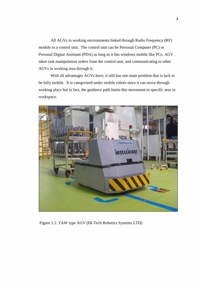
of AGV use in factories. Moreover, some AGVs use forklifts to lift objects for
storage as the one shown in Figure 1.1.
AGV uses predefined path for guidance purpose in warehouse or factory.
Two main technologies AGV uses for guidance, which are magnetic wire and
colored tapes. In wire guidance, a wire emitting radio waves fixed in a slot cut in
factory floor and a detecting sensor placed on the bottom of the robot facing the
floor. The sensor detects the radio waves being transmit from the wire and follows
it. Tape guidance technology can be in two types: magnetic or colored. AGV uses
proper sensor to detect the tape as show in Figure 1.1, which uses colored tape.
Using color or magnetic guidance has advantage over wired guidance, as it is easy in
installation and can be relocate from place to another flexibly. Additionally, it is
considered a "passive" system since it does not require the guide medium to be
energized as wire does.
4
All AGVs in working environments linked through Radio Frequency (RF)
module to a control unit. The control unit can be Personal Computer (PC) or
Personal Digital Assistant (PDA) as long as it has windows mobile like PCs. AGV
takes task manipulation orders from the control unit, and communicating to other
AGVs in working area through it.
With all advantages AGVs have, it still has one main problem that is lack to
be fully mobile. It is categorized under mobile robots since it can move through
working place but in fact, the guidance path limits this movement to specific area in
workspace.
Figure 1.1: TAW type AGV (HI-Tech Robotics Systemz LTD)
5
1.3 Problem statement
To make AGVs fully mobile it is important to find a way of guidance rather than
ordinary wired or tape guidance technologies. If the AGV navigated, free of
guidance paths thus finding its position in the factory or warehouse is essential
information for navigation process. Two main techniques can be used for mobile
robot positioning: relative and absolute techniques.
Relative positioning technique uses robot-heading angle and speed over time
to calculate travelled distance, and by knowing robot initial position the current
position of the robot can be determined. Mobile robots subjected to variation in
speed and wheel slippage that leads to drift errors with time and long travelled
distances (Liu et al., 2009).
In contrast, absolute positioning techniques do not rely on previous position
to determine new position of the mobile robot; e.g. Global Positioning System (GPS)
or landmarks so that; absolute techniques do not suffer from error drift problem.
Absolute positioning using, GPS has low accuracy and signal blockage inside
buildings so it cannot be used for mobile robot positioning (Jeehong & Lee, 2006).
Alternatively, landmarks widely using for indoor positioning, landmarks are
features in the environment that a robot can detect. Landmarks installed in
predefined position in working place so the robot can determine its position relative
to landmark (Atif et al., 2008). However, cost of landmarks is high and difficult to
install through all places in working environment especially, in case of factories or
large warehouse.
Integration between relative and absolute techniques can overcome the
shortcoming in each technique. Fusion of information from multiple sensors is
important, since combined information from multiple sensors can be more accurate.
In particular when not all sensors are able to sense the same; some features may be
occluded for some sensors, while visible to others. Together the sensors can provide
a more complete picture of the scene at a certain time. Multi-sensor fusion is also
important since it can reduce the effects of errors in measurements.
6
1.4 Research objectives
This research intended to develop positioning system (hardware and software) to
work as a replacement for AGVs ordinary guidance methods. Multi-sensor fusion
used to get the advantages of both relative and absolute positioning techniques.
Therefore, the objectives of this research are as following:
1. Design and fabricate of a positioning module electronic board with a wireless
radio to communicate with the control unit.
2. Implementation of positioning algorithm based on multi-sensor fusion (e.g.
digital compass, odometry, accelerometer, RFID, and ultrasonic GPS).
3. Enhancement AGV positioning by using RFID or ultrasonic GPS to eliminate
drift error from relative positioning techniques.
4. Develop graphical user interface program on PC or PDA, which can be
function as control unit for the AGV.
1.5 Scopes of the research
This research work focuses on developing sensor fusion system for AGV
positioning. Different positioning sensors have been used to develop the positioning
module electronic board such as, odometry, accelerometer, digital compass,
ultrasonic GPS, and RFID to combine relative and absolute positioning techniques.
Microcontroller used to acquire all sensor reading and send them to host PC via
Radio Frequency (RF) module. The host PC run software program written in
LabVIEW, sensor readings received from the microcontroller logged to positioning
algorithm on the LabVIEW program to estimate AGV position. Communication
between the positioning module electronic board and the PC established using Xbee
RF module. In order to validate the positioning system experiment has been carried
out to determine positioning accuracy and error value between actual and estimated
position of the AGV.
7
1.6 Summary
Mobile robot position is essential knowledge the robot needs to know before start
moving around in the environment. AGV as kind of mobile robots use wired or
magnetic tapes guidance systems to solve positioning problem. Hence, AGV can
only move based on the limits the guidance system gives to it. In order to make
AGV move freely in workspace, relative and absolute positioning techniques can be
used to as a replacement for ordinary guidance systems (wired or magnetic tapes
guidance). The rest of the thesis is outlined as following:
Chapter 2 discusses review of literature on different positioning approaches.
Advantages and disadvantages of relative and absolute positioning techniques
highlighted to come out with the proposed sensor fusion system to overcome
shortcoming of every technique.
Chapter 3 provides an overview of the research methodology and steps taken
to develop positioning system. It also covers briefly functions and theory of
operation of the selected sensors. Finally, the positioning algorithm and use of
LabVIEW are explained in details.
Chapter 4 discusses research outcomes and experimental results, which are
carried out by installing the developed positioning module electronic board on a
mobile robot to simulate AGV. Research conclusion and future work
recommendations are covered in Chapter 5.
CHAPTER 2
LITERATURE REVIEW
Different positioning techniques for mobile robot are covered in this chapter. The
aim of the literature is to get a good understanding of theory of operation,
advantages, and disadvantages of different mobile robots positioning approaches.
From the literature it can be concluded that multi-sensors fusion as a new approach
gives a better solution for positioning problem which can be used during this
research.
2.1 Relative positioning techniques
Relative techniques estimate current position of mobile robot based on speed and
heading angle of the robot and the time passed since the last known position. Mobile
robots are subjected to variation on moving speed and wheel slippage, therefore
small error in positioning will be accumulated and grow up unbounded with long
time-periods and travelled distances (Liu et al., 2009). An example of relative
positioning sensors is odometry and accelerometer.
9
2.1.1 Odometry
The word odometry originates from the Greek words hodos (meaning "travel",
"journey") and metron (meaning "measure") on other words odometry is travelled
distance measurement (Merriam-Webster, 2010). The odometry uses data from
robot actuators to estimate change in position over time relative to initial position.
Data from wheel encoders (for wheeled mobile robots) can be used to measure how
far the wheels have rotated, and if it knows the circumference of its wheels, travelled
distance then computed.
Since estimation of new position is based on the previous one, error in
position estimation will be accumulated over time, which so-called drift error.
Inequalities of wheel diameters, flatness of the road and wheel slippage are potential
causes of odometry errors (Houshangi & Azizi, 2006). It is therefore necessary to
augment the use of odometry by integrating it with another positioning sensor types.
Vast studies have been made on odometry for error correction by utilizing another
sensor along with odometry.
Houshangi and Azizi (2006) studied effect of using gyro with odometry for
mobile robots position determination. Robot position and orientation calculated by
integrating speed information from encoders and rotational rate from gyro,
respectively. Houshangi and Azizi proposed two kinds of odometry errors: these
errors are categorized as systematic (e.g. different wheel diameters), and
nonsystematic (e.g. wheel slippage) errors. Position result by data integration of
gyro with the odometry showed reduction of positioning error from 809 mm to 37
mm over 30-meter of travelled distance.
Odometry integrated with compass for navigation purpose of team of LEGO
Robots (Pasztor et al., 2010). Pasztor et al, used odometry data to determine
travelled distance of LEGO Robot however, error in position of the robot for 20-
meter long was 11-meter which about 50% of the total travelled distance. The
robot‟s direction differs so enormous from their original one thus, odometry alone as
a solution for positioning not enough.
Pasztor et al combined digital compass to keep the robot in the specified path,
in this method, the robot navigation program saved the starting angle (λb), and then
by synchronizing wheels, the robot went towards the target position. When during
10
walking the difference of actual direction (λa) reached 1o degree from the original
one, the robot suspended the synchronization between the wheels, and rotated the
adequate wheel until (λb - λa = zero) obtained. Integrating the compass made
enormous reduction in robot error for travelled distance 20-meter, which become 28
cm in final X position of the robot.
2.1.2 Accelerometer
Accelerometer is a sensor produce electric signal proportional to acceleration of the
moving body (i.e. mobile robot); the produced electric signal can be in form of
voltage or current. Acceleration value of the mobile robot can be used to estimate
position by integrating acceleration, once for obtaining the speed, twice for obtaining
the travelled distance by the robot (Andres et al., 2006).
Position estimation is independent of external information sources. However,
since measurements are made by integration, the position estimates drift error over
time, and thus the errors increase without bound. Another source of error is
sensitivity to bumpy ground, if there is a bump in the floor; the sensor will detect a
component of the gravitational acceleration.
Andres et al (2006) carried experiment on using 2-axis accelerometer and two
encoders as positioning sensors for dual drive mobile robot. The system based on
fusion of data from the accelerometer and encoder then, log sensors information to
Kalman filter for position estimation. Resultant position error in X and Y position of
the robot was (5.5, 6.0) cm by using encoders data alone, (1.0, 25) cm by using data
from accelerometer alone, and (2.0, 4.0) cm as result of data fusion of encoder and
accelerometer. The error range from this system is accepted but, that study did not
mention the travelled distance of the robot during the experiment, accelerometers are
suitable as positioning sensors for short travelled distances. Another weakness of
that study is Andres did not measure the acceleration of z-axis to give feedback about
the floor flatness, which is source of error in encoder and accelerometer data as well.
11
Better results from accelerometer can be obtained by extracting the
acceleration of gravity from accelerometer output (Oh Chul & Kiheon, 2009). If the
robot at rest the accelerometer output is, gravity acceleration once start accelerates
the output will be combination of body acceleration and acceleration of gravity.
Chul and Kiheon (2009) aimed to develop attitude reference system using 3-axis
accelerometer, they developed algorithm to extract acceleration of gravity from
accelerometer output data. The developed system by Chul and Kiheon can be used
to control the attitude of robots and integrate it with odometry positioning technique
to enhance odometry positioning by giving feedback about floor flatness as discussed
in previous section.
Wong et al (2008) proposed a novel for using accelerometer as a balance
sensor for humanoid robots to measure Zero Moment Point (ZMP) of the robot body.
A 3-axis accelerometer sensor is mounted on the robot for determining the rotate
angle velocity of the humanoid robot. Fuzzy controller is used to control the motions
of the robot to adjust the posture of the robot for static balancing using acceleration
value. Experiments results showed that accelerometer integration with fuzzy control
able to adjust the posture of the robot to change its center of gravity for different
standing environment so that the humanoid robot can balance and stand on an
inclined plane by itself.
2.2 Absolute positioning techniques
In contrast with relative positioning; absolute positioning techniques estimates robot
position independent of the previous location. Position estimation is not derived
from integration of sampled sensor measurement. Robot position been computed in
the global coordinates using the distances from some reference positions in the
working environment (Hwang et al., 2006). This technique has the advantage that
the error in robot position does not grow increasingly. Absolute positioning has
many categories but the following will be taken into consideration:
I. Magnetic compasses
II. Landmark based positioning
12
2.2.1 Magnetic compass
Robot position in global co-ordinate system denote by its location relative to
Cartesian coordinate system and heading angle, (x, y, θ). Magnetic compass is a
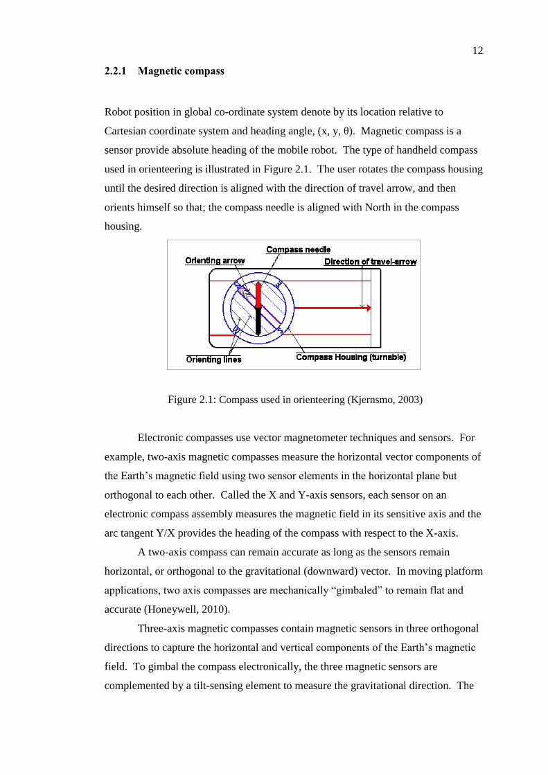
sensor provide absolute heading of the mobile robot. The type of handheld compass
used in orienteering is illustrated in Figure 2.1. The user rotates the compass housing
until the desired direction is aligned with the direction of travel arrow, and then
orients himself so that; the compass needle is aligned with North in the compass
housing.
Figure 2.1: Compass used in orienteering (Kjernsmo, 2003)
Electronic compasses use vector magnetometer techniques and sensors. For
example, two-axis magnetic compasses measure the horizontal vector components of
the Earth‟s magnetic field using two sensor elements in the horizontal plane but
orthogonal to each other. Called the X and Y-axis sensors, each sensor on an
electronic compass assembly measures the magnetic field in its sensitive axis and the
arc tangent Y/X provides the heading of the compass with respect to the X-axis.
A two-axis compass can remain accurate as long as the sensors remain
horizontal, or orthogonal to the gravitational (downward) vector. In moving platform
applications, two axis compasses are mechanically “gimbaled” to remain flat and
accurate (Honeywell, 2010).
Three-axis magnetic compasses contain magnetic sensors in three orthogonal
directions to capture the horizontal and vertical components of the Earth‟s magnetic
field. To gimbal the compass electronically, the three magnetic sensors are
complemented by a tilt-sensing element to measure the gravitational direction. The
13
tilt sensor provides two-axis measurement of compass assembly tilt, known as pitch
and roll axis. The five sensor inputs are combined to create a “tilt-compensated”
version of the X and Y-axis magnetic vectors, and then computed into a tilt
compensated heading (Honeywell, 2010).
One disadvantage of any magnetic compass, however, is that the earth‟s
magnetic field is often distorted near power lines or steel structures. This makes the
straightforward use of geomagnetic sensors difficult for indoor applications
(Borenstein et al., 1997).
Experimental study on KVH C-100 Fluxgate shows that when compasses are
used on mobile robots, carefully tuned digital low pass filters are very effective in
minimizing errors produced by vibration (which can produce errors up to 10°). The
study concludes that electronic compasses have good potential to be useful in mobile
robot positioning, especially as part of a multi-sensor system, in which other sensor
modalities can take over when needed (Ojeda & Borenstein, 2000).
Another study on using compass reading inside structured area as a magnetic
signature detector to specify the current location in the environment based on
magnetic field value of the location has been carried out by Suksakulchai
(Suksakulchai et al., 2000). The experiment was successful and the robot was able to
recognize all places while travelling to the goal. The computation time was very
rapid, and memory space used in consumption is very small. This technique can be
used with a topological map or odometry itself as an external reference.
As a part of sensor fusion compass is widely used for heading measurement
since it cannot be used as the only tool for robot positioning and navigation. A
compass and two IR sensors oriented at 90◦ to sense the environment used in
(Peasgood et al., 2005). Another study using digital compass as heading sensor in
biomimetic legged robot the sensor shows sensitivity and error in reading due to
change in tilt of the robot relative to horizontal. Accelerometer was used together
with the compass as tilt sensor which shows improvement in heading angle reading
(Anđelković et al., 2003).
14
2.2.2 Landmarks based positioning
Landmarks refer to feature or object in the environment around the robot that can be
recognized by it. Each landmark has prior information in the robot memory; this
information is landmark position in Cartesian coordinate. Thus, once the robot
detects three or more landmarks it can calculate it position using triangulation or
trilateration (Ozawa et al., 2007). Triangulation techniques use distances and angles
between the robot and the landmark; trilateration techniques only use distances. The
angles and/or distances are then used to calculate the position and orientation of the
robot (Singhal, 1997). Landmarks can be categorized as following:
I. Active landmarks
II. Passive landmarks
a. Passive natural landmarks
b. Passive artificial landmarks
If the landmarks actively send out signals for the robot to discover that it
exists, the landmark is so-called active landmarks. These signals can be inform of
infrared, RF (Radio Frequency) signal from satellite like GPS, ultrasonic, or RFID
(Radio Frequency Identification) signal from active RFID tag (Lee & Song, 2007).
In contrast, passive landmarks do not actively send signals therefore; the
robot has to look for the landmarks and estimate its position relative to the
landmarks. Passive landmarks either can be part of the workspace such as doors and
windows, which is called natural landmarks or landmarks designed to be recognized
by robots, which is called artificial landmarks. Artificial landmarks such as bar
codes, passive RFID tags, or colored geometric figures, like squares and circles.
Use of landmarks in mobile robot positioning has various styles based on
type of landmark and sensor used to detect it. For example, a color artificial
landmark system proposed by Guo and Xu (2006) in which the red number patterns
installed in predefined positions. The robot equipped with camera to detect
landmarks. By detecting, recognizing, and locating an artificial landmark, the mobile
robot can calculate its own position and heading with respect to the landmark frame.
Ozawa et al (2007) used vision system to for mobile robot positioning by
recognizing visual natural landmarks. The developed algorithm by Ozawa applied
15
on RoboCup soccer game, the landmark was the target and the ball. Average
positioning error from the algorithm 21 cm, indeed accuracy of using vision system
for landmarks recognition depends on distance between the landmark and the vision
sensor. The further away a landmark is from a robot, the less accurate position
estimation.
In the methods using natural landmarks, robust extraction of natural
landmarks is a difficult task (Guo & Xu, 2006). However, artificial landmarks are
very simple and powerful for accurate localization. RFID is an example of artificial
landmarks; RFID can be active or passive landmarks depend on tag type as will be
explained in detail in section 2.5.
2.3 Global positioning system (GPS)
GPS has been developed by United States to be used by the Department of Defense
in order to provide a positioning service for US military. Nowadays, GPS is also
used for commercial purposes such as nautical, aeronautical, ground based
navigation, and land surveying. The current US based GPS satellite constellation
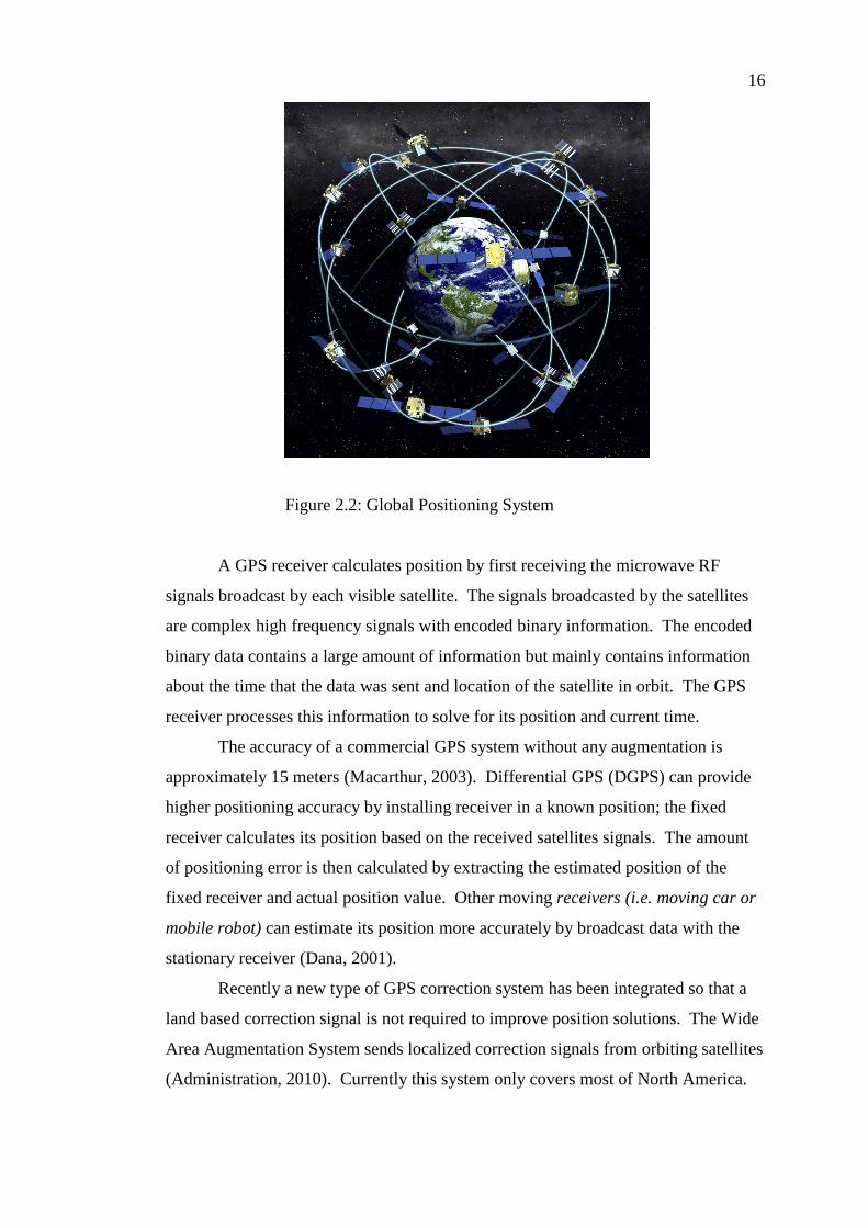
system consists of a 24-satellite system as shown in Figure 2.2.
The number of satellites for this system can vary due to satellites being taken
in and out of service. Other countries are leading efforts to develop alternative
satellite systems for their own GPS systems. A similar GPS system is the
GLONASS constructed by Russia. Each satellite maintains its own specific orbit and
circumnavigates earth once every 12 hours. The orbit of each satellite is timed and
coordinated so that five to eight satellites are above the horizon of any location on
the surface of earth at any time (Dana, 2001).
16
Figure 2.2: Global Positioning System
A GPS receiver calculates position by first receiving the microwave RF
signals broadcast by each visible satellite. The signals broadcasted by the satellites
are complex high frequency signals with encoded binary information. The encoded
binary data contains a large amount of information but mainly contains information
about the time that the data was sent and location of the satellite in orbit. The GPS
receiver processes this information to solve for its position and current time.
The accuracy of a commercial GPS system without any augmentation is
approximately 15 meters (Macarthur, 2003). Differential GPS (DGPS) can provide
higher positioning accuracy by installing receiver in a known position; the fixed
receiver calculates its position based on the received satellites signals. The amount
of positioning error is then calculated by extracting the estimated position of the
fixed receiver and actual position value. Other moving receivers (i.e. moving car or
mobile robot) can estimate its position more accurately by broadcast data with the
stationary receiver (Dana, 2001).
Recently a new type of GPS correction system has been integrated so that a
land based correction signal is not required to improve position solutions. The Wide
Area Augmentation System sends localized correction signals from orbiting satellites
(Administration, 2010). Currently this system only covers most of North America.
17
GPS has poor accuracy to be used as positioning technique for mobile robot
applications specially, if the robot is being used for manipulation tasks. Another
limitation is signal blockage problem inside buildings or in cloudy days since GPS
positioning rely on received signal from satellites. Therefore, ultrasonic GPS themes
seem to be a good solution for mobile robot absolute positioning indoors.
2.4 Ultrasonic indoor GPS
To date several methods proposed to estimate the position of a mobile robot using
ultrasonic sensors, one of them is using two artificial landmarks to determine the
mobile robot‟s current position and orientation. In (Feng-ji et al., 1997), sixteen
sonar sensors mounted around the mobile robot are used to detect obstacles. The
purpose was to provide an estimation of the robot‟s absolute position and orientation
in its working space. Using map matching from sonar sensors and matches it to the
real working place map. Error in position and orientation from this system was 10cm
and 10 deg.
Ghidary (1999) developed home robot localization system; the localization
method utilizes ultrasonic and infrared signals simultaneously. The transmitter,
which is mounted on the mobile robot, transmits both ultrasonic and infrared signals
at the same time. The receivers are located at fix points in the ceiling of the room
use the received infrared signal as a trigger to measure The Time Of Flight (TOF) of
ultrasonic waves. The location of robot is computed by measuring its distance from
three receivers. The heading of the robot is computed by measuring its position in
two successive points while the robot moves from one point to the other. The
performance and validity of this system are evaluated using one transmitter and six
receivers located in a 6m x 4m room. Error in positioning was less than 5 cm in X
and Y position.
Shoval (1999) used ultrasonic sensors for the measurement of angular
position of a mobile robot relative to a known ultrasonic source. In this work
proposed using of phase difference measurement to determine a mobile robot‟s
angular position relative to a known ultrasonic source. Two ultrasonic sensors
attached to the sides of the robot, and serve as receivers. A third sensor is positioned
18
at an off-board location. This sensor only transmits signals at a rate controlled by the
mobile robot (control and synchronization can be achieved by radio link but in our
bench top set-up a wired link was used). When the transmitting sonar fires an
ultrasonic wave, the two receivers are set for “listening mode” ready to receive the
signals. A fast measurement system calculates the phase difference between the
received signals in both sonar, where the magnitude of the phase difference is
proportional to the difference of the Euclidean distance between the receivers and the
transmitter.
Based on ultrasonic sensory information, an approach is proposed for
localization of autonomous mobile robot (AMRs). In the proposed method, it is
proven that the combination of three ultrasonic transmitters and two receivers can
determine both the position and the orientation of an AMR with respect to a
reference frame uniquely. In this manner, since only ultrasonic sensors are used, the
proposed method will be highly cost-effective and easy to implement (Wu & Tsai,
2001). Such localization system not possible to be used in real applications because;
the transmitters installed very near to each other only 20 cm apart which mean small
coverage area. The experiment done in static mode the robot was not moving and
that is not the case in mobile robot applications.
Shoval (2001) presented a method for measuring the relative position and
orientation between two mobile robots using a dual binaural ultrasonic sensor
system. Each robot is equipped with a sonar transmitter that sends signals to two
receivers mounted on the other robot. It is assumed (but not implemented in this
system) that the two robots can synchronize events with an infrared or radio link.
The receivers measure the distance to the transmitter on the other robot, and a
geometric model determines the relative position and orientation of the two robots
based on a combination of the data from all four receivers.
In Shoval (2001), experimental results show the accuracy and operational
limitations of the technique. The described method can assist multi-robot systems
where cooperation is required in terms of relative position and orientation. In
addition, the system can be implemented in tasks where a single robot is required to
position itself accurately against other point. For example, a stationary
transmitter/receiver setup can be installed in docking stations, doorways or narrow
passageways to guide the robot to the desired position and orientation regardless of
the accuracy of its other positioning systems. The simplicity of operation and the low
19
cost for the obtained accuracy make the system advantageous for implementation is
multi-robot system or in industrial environments.
In Hwang et al (2006) indoor GPS system using ultrasonic sensor has been
built, this system consists of one transmitter having ultrasonic and RF and two
receivers. The transmitter irradiates RF and ultrasonic, and the receivers calculate
corresponding distance with reference to the RF signal. The two distance values are
used for determining the location of the transmitter by trigonometrical functions.
Due to the characteristics of ultrasonic sensors, noise occurs in sensor values by
surrounding temperature or obstacle. Location error is minimized by prediction and
correction of the noise with Linear Kalman Filter. In order to prove the effectiveness
of this system, experiments were carried out in a room dimensioned by 3.5m*2.2m,
wherein the location error showed 2cm max in x and y position.
Ultrasonic GPS has high positioning accuracy for indoor applications with
the fact that, reflection of ultrasonic wave in case of dynamic environment leads to
error in positioning. Moreover, coverage area for most ultrasonic transducers is only
2-meter; as a result, ultrasonic GPS to be used in factories or large warehouses need
to spread large number of ultrasonic transmitter modules as well. Using large
number of ultrasonic transmitters has health drawback on labors in the place and
increasing the positioning system cost.
2.5 Radio Frequency IDentification (RFID)
RFID is a term referring to a type of system where communication between the
constituent components (e.g. RFID reader and tag) is realized using Radio
Frequency (RF) or magnetic field variations. Every RFID tag has a unique
identification number so that, the tag usually attached to the object that is being
identified.
The reader is the device that can detect the presence of tags, and read
information stored on the tags. After a successful read, the reader can then notify
some other system about the presence of a tag, and forward fetched data for further
processing. Tags often incorporate a so-called UID, an abbreviation for Unique
IDentifier. In this context, each tag uniquely identify by data bits located in the
20
memory areas. More advanced tags also offer a general-purpose, non-volatile, user-
programmable memory, so that information about the attached object can be stored
in the tag itself, and not in a separate storage system.
In a separate storage system, the information about attached objects are stored
in database (DB). It should be emphasized that a tag works as both a transmitter and
a receiver; a tag intercepts an RF signal, and then transmit a response. This also
applies to the reader. Moreover, both readers and tags make use of antennas to
manage communication. However, RFID tags are usually seen as a way of doing
identification, there is nothing that says it must be used for this purpose only. RFID
tag can be seen as a general purpose, wireless-accessed storage device, usable for
many more applications than just identification.
2.5.1 Types of RFID tags
A common way of categorizing different types of RFID tags is by how they obtain
power. This characteristic is actually a major factor for the size, cost, and longevity
of a tag; passive tags obtain their power by means of utilizing the RF signal sent out
from the reader; active tags use an internal power source in the form of a battery cell.
Traditionally, tags that make use of an on-board power source for some of its
function, and the RF signal of the reader for other functions, have been referred to as
active as well. A more recent term for this type of tags is semi-passive. This section
will only focus on passive and active tags (Johansson, 2008).
2.5.1.1 Passive RFID tags
The most notable feature of passive tags is that they completely lack an internal
power source; they are powered solely by an electric current induced in the antenna
of the tag by the reader‟s RF signal. Often, this induced current is just enough to
power up the tag, calculate the response, and finally transmit the response back to the
reader. This is the reason why passive tags have limited capabilities compared to
active tags.
21
Passive tags obtain power from the reader‟s RF signal by a phenomenon
known as the near field. It occurs when the magnetic part of the RF signal is
powerful enough to induce a current in a coil. Induction is based on the property that
when a coil is placed in an alternating magnetic field, energy is drawn from the field,
resulting in a voltage in the coil. This means that in a system of passive tags, both
readers and tags use coils, and not conventional radio antennas. As suggested by the
name, the near field is only available in vicinity close to the reader‟s antenna; the
strength of the magnetic field decline very fast.
The advantage of passive tags (compared the active tags) are generally low
price, small size, and a simpler manufacturing process. Apparent disadvantages
include a small memory capacity, and limited calculation abilities. Usually, the
limited range is also considered as a disadvantage. In this project, the limited range
of passive tags has actually been an advantage (Johansson, 2008).
2.5.1.2 Active RFID tags
The major characteristic of active tags is that they use an internal power source, i.e.,
batteries, and with these follow larger possibilities in almost every respect compared
to passive tags. For example, since a battery is used to power the circuitry, it is
possible to transmit and receive without having to be powered by the near field of the
reader‟s antenna. More importantly, the limited communication range imposed by
the near field does not apply.
The advantages of active tags (compared the passive tags) are generally
higher memory capacity and higher calculation abilities (perhaps encryption of
transmitted data to prevent eavesdropping). Moreover, communication is often more
reliable, due to the more reliable power source. Disadvantages are generally higher
price, and larger in size (Johansson, 2008).
22
2.5.2 RFID frequency bands
RFID tags fall into three regions in respect to frequency:
Low frequency (LF, 30 - 500 kHz)
High frequency (HF, 10 - 15MHz)
Ultra high frequency (UHF, 850 - 950MHz, 2.4 - 2.5GHz, 5.8GHz)
Low frequency tags are cheaper high frequency tags. They are fast enough
for most applications, however for larger amounts of data the time a tag has to stay in
a readers range will increase. Another advantage is that low frequency tags are least
affected by the presence of fluids or metal. The disadvantage of such tags is their
short reading range. The most common frequencies used for low frequency tags are
125 - 134.2 kHz and 140 - 148.5 kHz.
High frequency tags have higher transmission rates and ranges but also cost
more than LF tags. Smart tags are the most common member of this group and they
work at 13.56MHz. UHF tags have the highest range of all tags. It ranges from
three to six meters for passive tags and 30- meters for active tags. In addition, the
transmission rate is also very high, which allows to read a single tag in a very short
time. This feature is important where tagged entities are moving with a high speed
and remain only for a short time in a readers range. UHF tags are also more
expensive than any other tag and are severely affected by fluids and metal. Those
properties make UHF mostly useful in automated toll collection systems. Typical
frequencies are 868MHz (Europe), 915MHz (USA), 950MHz (Japan), and 2.45GHz.
Frequencies for LF and HF tags are license exempt and can be used worldwide;
however, frequencies for UHF tags differ from country to country and require a
permit.
23
2.5.3 RFID for mobile robots positioning
In recent years, RFID has attracted economic, public, and scientific interest. RFID
has found its way into robotics, it promises improvements in self-localization,
mapping, and navigation in general. Among the various interesting properties of
RFID, the probably most important is that objects equipped with RFID tags can be
identified uniquely (Schneegans et al., 2007). One of the first surveys into how to
localize a mobile robot via RFID is the one presented by Hahnel et al (2004).
In Hahnel et al (2004) a probabilistic sensor model for their RFID reader was
proposed, which associates the probability of detecting an RFID tag with the relative
position of that tag with respect to the antenna. This model was used to map the
positions of passive RFID tags in an office environment, given a previously
computed map learned via a laser-based SLAM (Simultaneous Localization and
Mapping) algorithm. The position of each tag was represented by a number of
particles, whose weights were updated after each position reading of the tag. Monte
Carlo localization was then used to estimate the position of the robot in the map,
using another set of particles to represent the robot pose. Hahnel proposed system
achieve robust self-localization based on RFID data and odometry alone.
Furthermore, self-localization was greatly accelerated, and the required
number of particles could be reduced if the data of laser scanner and RFID reader
were combined as compared to localization with a laser scanner only. A somewhat
similar work, originally intended to locate nomadic objects, is the one by (Liu et al.,
2006). They demonstrated a system for passive UHF (Ultra-High Frequency) tags,
which exploits the directionality of RFID readers. Beliefs of the positions of tagged
objects are formed from varying robot poses over time. Successfully examined how
support vector machines could learn robot locations In (Yamano et al., 2004). They
generated feature vectors out of signal strength information gained from active RFID
tags. Djugash utilized active RFID tags in an outdoor environment (Djugash et al.,
2005). They used time-of-flight measurements both for pure self-localization and for
simultaneous localization and mapping based on Kalman and particle filters. In the
context of passive high frequency (HF) tags operating at 13.56 MHz, Bohn has
furthermore examined how tags densely spread on the floor allow for location
estimation (Bohn, 2007).
24
Tsukiyama explored a simple navigation mechanism based on vision for free
space detection and RFID tags as labels within a topological map of an indoor
environment (Tsukiyama, 2003). Kulyukin et al (2006) have also studied navigation
based on passive RFID tags. Their robotic guide was able to assist visually impaired
people in way finding in indoor environments. Kleiner (2006) studied the use of
RFID labels for the coordination of robot teams in exploration, during which the
labels were autonomously deployed. Recently, Zhou proposed a vision-based indoor
localization method in which they used modified active RFID tags as landmarks
(Zhou et al., 2007). The tags were equipped with bright LEDs to be recognized. An
additional laser diode allowed for the selective activation via a laser beam emitted by
the robot. A prototype system, which lacked the ability of autonomously point a
laser at visually recognized RFID labels, promised accurate localization. Note that
the laser activation step requires line-of-sight, which is generally not the case for
other RFID-based localization approaches.
Chon et al (2004) presented RFID localization system to replace GPS in
tunnels and structured areas in which GPS signal become weak of blocked. The
method presented in that research suggested to be used for outdoor applications to
localizes city cars by the same way GPS can do. The idea is to install RFID tags in
predefined positions and store tags ID and location on database system. Every car
has to have RFID reader Fixed on it. The cost is low and easy to implement for
mobile robot applications for indoor and outdoor localization.
2.6 Summary
Dead reckoning provides location data by accumulating the travelled distance from a
known initial position. The moving distance and direction of a robot can be detected
with sensors such those based on the vehicle‟s an odometer with optical encoders,
and magnetic compass. On the rough of the ground the travelled distance, produce a
high-accumulated error. This error is caused mainly by wheel slip. Therefore, it
cannot be used as a unique method for attaining a precise position of the vehicle
during a large period.
REFERENCES
Administration, F. A. (n.d.). Wide Area Augmentation System. Retrieved April 1,
2010, from http://gps.faa.gov/Programs/WAAS/waas.htm
Administration, F. A. (2010). Wide Area Augmentation System. Retrieved April 1,
2010, from http://gps.faa.gov/Programs/WAAS/waas.htm
Anđelković, S., Veličković, I., Rašić, M., & Đorđević, G. S. (2003). Digital Compass
as Heading Sensor for Hexapod Robot. JOURNAL OF AUTOMATIC
CONTROL UNIVERSITY OF BELGRADE , 13 (2), 11-16.
Andres, G., Guayacundo, & Marcela, D. (2006). Evaluation of Accelerometers as
Inertial Navigation System for Mobile Robots. Robotics Symposium, 2006.
LARS '06. IEEE 3rd Latin American, (pp. 84-90).
Atif, M., Kulik, L., & Tanin, E. (2008). Autonomous navigation of mobile agents
using RFID-enabled space partitions. 16th ACM SIGSPATIAL international
conference on Advances in geographic information systems. California .
Beom, H., & Cho, H. (1995). Mobile robot localization using a single rotating sonar
and two passive cylindrical beacons. Robotica,Cambridge university press ,
13, 243-252.
Bohn, J. (2007). Prototypical Implementation of Location-Aware Services based on a
Middleware Architecture for Super-Distributed RFID Tag Infrastructures.
Personal and Ubiquitous Computing Journal .
67
Borenstein, J. (1995). Control and kinematic design of multi-degree-offreedom.
Borenstein, J., & Feng, L. (1996). Measurement and correction of systematic
odometry errors in mobile robots. IEEE Transactions on Robotics and
Automation 12.
Borenstein, J., & Feng, L. (1996). Measurement and correction of systematic
odometry errors in mobilerobots. (12), 869-880.
Borenstein, J., Everett, H., Feng, L., & Wehe, a. D. (1997). Mobile robot positioning:
Sensors and techniques. Journal of Robotic Systems 14,4 , 231-249.
Chon, H. D., Jun, S., Jung, H., & An, S. W. (2004). Using RFID for Accurate
Positioning. Journal of Global Positioning Systems , III (1), 32-39.
Cox, I. J., & Blanche. (1991). Position estimation for an autonomous robot vehicle
(Vol. II). Los Alamitos, CA,USA: IEEE Computer Society Press.
Cox, I. J., & Wilfong, G. (1990). Autonomous Robot Vehicles. New York, NY, USA:
Springer-Verlag New York, Inc.
Dana, P. H. (2001). Global Positioning System Overview. Retrieved 4 1, 2010, from
http://www.colorado.edu/geography/gcraft/notes/gps/gps.html
Djugash, J., Singh, S., & Corke, P. (2005). Further Results with Localization and
Mapping using Range from Radio. Proc. of the International Conference on
Field & Service Robotics (FSR '05).
Djugash, J., Singh, S., & Corke, P. (July 2005). Further Results with Localization
and Mapping using Range from Radio. Proc. of the International Conference
on Field & Service Robotics (FSR '05).
68
Elfes, A. (1990). a stochastic spatial representation for active robot perception.
Proceedings of the Sixth Conference of Uncertainty in AI, (pp. 60-70).
Farebrother, R. (1988). Linear least squares computations. Marcel Dekker Inc.
Feng-ji, Z., Hai-jiao, G., & Abe, K. (1997). A Mobile Robot Localization Using
Ultrasonic Sensors in Indoor Environment. 6th IEEE International Workshop
on Robot and Human Communication, (pp. 52-57). Sendai, Japan.
Fox, D., Burgard, W., & Thrun, S. (1999). Markov localization for mobile robots in
dynamic environments. 391-427.
Ghidary, S. S., Tani, T., Takamori, T., & Hattori, M. (1999). A new Home Robot
Positioning System (HRPS) using IR switched multi ultrasonic sensors. IEEE
International Conference on Systems, Man, and Cybernetics, V, pp. 737-741.
Tokyo, Japan.
Guo, Y., & Xu, X. (2006). Color Landmark Design for Mobile Robot Localization.
IMACS Multiconference on "Computational Engineering in Systems
Applications"(CESA), (pp. 1868-1874). China.
Hahnel, D., Burgard, W., Fox, D., Fishkin, K., & Philipose, M. (2004). Mapping and
Localization with RFID Technology. IEEE International Conference on
Robotics and Automation (ICRA).
Honeywell. (2010). Honeywell Electronic Compassing Solutions. Retrieved from
http://www.ssec.honeywell.com/magnetic/landnav.html
Houshangi, N., & Azizi, F. (2006). Mobile Robot Position Determination Using Data
From Gyro and Odometry. World Automation Congress. Hungary.
69
Hwang, K.-H., Kim, D.-E., Lee, D.-H., & Kuc, T.-Y. (2006). A Simple Ultrasonic
GPS System for Indoor Mobile Robot System using Kalman Filtering. SICE-
ICASE International Joint Conference, (pp. 2915-2918). Busan, Korea.
Jeehong, K., & Lee, C.-g. (2006). Location and position recognizing method by
wireless Ethernet signal strength in indoor. IEEE International Conference on
Industrial Technology, ICIT 2006. , (pp. 670 - 674 ).
Johansson, R. (2008). Navigation on an RFID Floor. MSc Thesis, Orebro
Universitet, Sweden.
Kjernsmo, K. (2003). How to Use a Compass. Retrieved from http://www.learn-
orienteering.org/old/
Kulyukin, V., Gharpure, C., Nicholson, J., & Osborne, G. (2006). Robot Assisted
Wayfinding for the Visually Impaired in Structured Indoor Environments.
Autonomous Robots , 1 (21), 29–-41.
Lee, J. M. (2005). Indoor Localization Scheme of a Mobile Robot Using RFID.
International Symposium on Humanized Systems. Wuhan, China.
Lee, S., & Song, J.-B. ( 2007). Mobile Robot Localization using Infrared Light
Reflecting Landmarks. International Conference on Control , Automation
and Systems. Korea.
Liu, S.-H., Huang, T.-S., & Yen, J.-Y. (2009). Comparison of sensor fusion methods
for an SMA-based hexapod biomimetic robot. Robotics and Autonomous
Systems .
Liu, X., Corner, M., & Ferret, P. S. (2006). RFID Localization for Pervasive
Multimedia. Ubicomp. Irvine, CA.
70
Macarthur, D. K. (2003). Design And Implementation Of An Ultrasonic Position
System For Multiple Vehicle Control. MSc Thesis, The University Of Florida.
Macarthur, D. K. (2003). DESIGN AND IMPLEMENTATION OF AN ULTRASONIC
POSITION SYSTEM FOR MULTIPLE VEHICLE CONTROL. MSc Thesis,
THE UNIVERSITY OF FLORIDA.
Merriam-Webster. (1998). Merriam-Webster's Collegiate Dictionary (10 ed.). Spring
field, MA: Merriam-Webster, Inc.
Merriam-Webster. (2010). Merriam-Webster's Collegiate Dictionary. Retrieved July
07, 2010, from http://www.merriam-webster.com/
Negenborn, R. (2003). Robot Localization and Kalman Filters On finding your
position in a noisy world. MSc Thesis, UTRECHT UNIVERSITY.
Oh Chul, H., & Kiheon, P. (2009). Estimating Accelerated Body's Attitude Using an
Inertial Sensor. ICROS-SICE International Joint Conference 2009. Japan.
Ojeda, L., & Borenstein, J. (2000). Experimental Results with the KVH C-100
Fluxgate Compass in Mobile Robots. IASTED International Conference
Robotics and Applications. Honolulu, Hawaii, USA.
Ozawa, R., Mae, Y., & Minami, M. (2007). Localization of Mobile Robots by
Multiple Landmark Recognition. SICE Annual Conference 2007, (pp. 1529-
1535). Japan.
Pasztor, A., Kovacs, T., & Istenes, Z. (2010). Compass and Odometry Based
Navigation of A Mobile Robot Swarm Equipped by Bluetooth
Communication. International Joint Conference on Computational
Cybernetics and Technical Informatics (ICCC-CONTI), (pp. 565-570).
71
Peasgood, M., Clark, C., & McPhee, J. (2005). Localization of Multiple Robots with
Simple Sensors. IEEE International Conference on Mechatronics &
Automation. Niagara Falls, Canada.
Schneegans, e., Vorst, P., & Zell, A. (2007). Using RFID Snapshots for Mobile
Robot Self-Localization. THE 3RD EUROPEAN CONFERENCE ON
MOBILE ROBOTS (ECMR 2007).
Shoval, S., & Borenstein, J. (1999). Measurement Of Angular Position Of A Mobile
Robot Using Ultrasonic Sensors. ANS Conference on Robotics and Remote
Systems. Pittsburgh, PA.
Shoval, S., & Borenstein, J. (2001). Measuring The Relative Position And
Orientation Between Two Mobile Robots With Binaural Sonar. the ANS 9th
International Topical Meeting on Robotics and Remote Systems. Washington.
Siegwart, R., & Nourbakhsh, I. (2004). Introduction to autonomous mobile robots.
London: Cambridge, MA: MIT Press.
Singhal, A. (1997). Issues in Autonomous Mobile Robot Navigation.
Singhal, A. (1997). Issues in Autonomous Mobile Robot Navigation. Master‟s thesis.
Suksakulchai, S., Thongchai, S., Wilkes, D. M., & Kawamura, K. (2000). Mobile
Robot Localization using an Electronic Compass for CorridorEnvironment.
IEEE international conference on systems, man and cybernetics. Tennesee.
Thrun, S., Beetz, M., Bennewitz, M., Burgard, W., Cremers, A., Dellaert, F., et al.
(2000). Probabilistic algorithms and the interactive museum tour-guide robot
minerva. International Journal of Robotics Research 19,11 .
72
Thrun, S., Fox, D., Burgard, W., & Dellaert, F. (2001). Robust monte carlo
localization for mobile robots. I-II, 99-141.
Tsukiyama, T. (2009). Mobile Robot Localization From Landmark Bearings. XIX
IMEKO World Congress Fundamental and Applied Metrology. Lisbon,
Portugal.
Tsukiyama, T. (2009). MOBILE ROBOT LOCALIZATION FROM LANDMARK
BEARINGS. XIX IMEKO World Congress Fundamental and Applied
Metrology. Lisbon, Portugal.
Tsukiyama, T. (2003). Navigation System for Mobile Robots using RFID Tags.
Proc. of the 11th International Conference on Advanced Robotics (ICAR
2003), (pp. 1130–-1135). Coimbra, Portugal.
Wong, C.-C., Cheng, C.-T., Chen, H.-C., Hu, Y.-Y., & Yin, C.-S. (2008). Static
Balancing Control of Humanoid Robot based on Accelerometer. SICE
Annual Conference 2008. Japan.
Wu, C.-J., & Tsai, C.-C. (2001). Localization of an Autonomous Mobile Robot
Based on Ultrasonic Sensory Information. Intelligent and Robotic Systems ,
30 (3), 267 - 277.
Yamano, K., Tanaka, K., Hirayama, M., Kondo, E., & Kimuro, Y. (2004). Self-
localization of Mobile Robots with RFID System by using Support Vector
Machine. IEEE/RSJ International Conference on Intelligent Robots and
Systems (IROS 2004), volume 4, pp. 3756–-3761.
Zhou, Y., Lu, W., & Huang, P. (2007). Laser-activated RFID-based Indoor
Localization System for Mobile Robots . Proc. of the 2007 IEEE
International Conference on Robotics and Automation, (pp. 4600–-4605).
Rome, Italy.