Embed Size (px)
Citation preview
Multi-Projector Multi-Camera Structured Light 3D Body Scanner
Tomislav PETKOVIĆ*1, Tomislav PRIBANIĆ1, Matea ĐONLIĆ1, Nicola D’APUZZO2 1 University of Zagreb, Faculty of Electrical Engineering and Computing, Zagreb, Croatia;
2 Hometrica Consulting, Ascona, Switzerland
DOI: 10.15221/17.319 http://dx.doi.org/10.15221/17.319
Abstract
Human body scanners using structured light are usually comprised of one projector which provides a limited view of the body surface due to limited field-of-view. To scan the whole surface of a human body multiple projectors must be used. Using more than one projector in a structured light scanner is typically difficult due to inter-projector interferences which make surface reconstruction a hard task. We propose to use temporal phase-shifts to enable multiplexing in fringe-projection profilometry. In our approach each projector projects a sinusoidal fringe pattern having its own specifically chosen set of temporal phase shifts so for a system of � projectors all temporal phase shifts together comprise a DFT���� basis. Such choice of temporal phase shifts enables simple and efficient separation of the combined pattern into the contributions of each projector. The proposed approach places no con-straints on the number of projectors and on spatial projector placement. We demonstrate the applicability of the proposed approach on a prototype human body scanner using three projectors and six cameras. Keywords: multi-projector human body scanner, simultaneous projector employment, fringe projector profilometry, frequency-division multiplexing, 3D body scanning
1. Introduction
The surface of a human body may be scanned using various techniques including structured light [1]. Two basic components of a structured light (SL) scanner are a projector and a camera. A projector projects coded light patterns onto an object which is then imaged by one or more cameras. Decoding the code of the observed pattern enables reconstruction of a surface profile of the imaged object. A majority of structured light (SL) scanners described in the literature use a single projector only [2,3,4]. Unfortunately, using a single projector significantly limits the imaged area due to a finite field-of-view (FOV) of the projector. As a consequence it is impossible to obtain a complete surface profile using a single projector only. Using more projectors and cameras extends the FOV of the scanner so the whole surface of an object may be imaged. Adding cameras to a SL scanner is trivial as camera is a passive device. However, adding projectors to a SL scanner is hard as projector is an active device: multiple projectors which share a common FOV always mutually interfere. This superposition of pat-terns from multiple projectors always makes pattern decoding hard and for certain SL patterns even impossible. Curiously, the projector interference problem is not often discussed hence almost all SL patterns described in the literature [2,3,5] are designed for a single projector. There are two approaches to using multiple projectors in a SL scanner: (1) projectors are employed sequentially in turns [6,7,8] and (2) projectors are employed simultaneously [9,10,11,12,13,14]. The first approach completely avoids the interference problem at the cost of extended scanning time which grows linearly with the number of projectors. As projectors are used in turns the sequential employ-ment allows one to select and use any of the various SL patterns described in the literature. The second approach offers significant advantage of shorter scanning times but has to cope with the in-ter-projector interference problem [6,14,15]. This usually requires specifically designed SL patterns which are insensitive to interference. There are currently only several multi-projector scanners de-scribed in the literature all of which solve the interference problem in different ways. The most common approach is to use different spatial orientation of projectors: Woolford and Brunett [9] describe a two-projector system where one projector uses horizontal and another vertical sinusoidal fringe; Je et al. [10] describe a two-projector system where one projector uses horizontal and another vertical color stripe pattern; and Sagawa et al. [11] and Furakawa et al. [12,13] describe a multi-projector system where each projector uses color line pattern with different spatial orientation. Other approaches described in the literature [16,17] are application limited and in general cannot be used to scan a hu-man body.
* [email protected]; +385 1 6129563; www.fer.unizg.hr
Proceedings of 3DBODY.TECH 2017 8th International Conference and Exhibition on 3D Body Scanning and Processing Technologies, Montreal, Canada, 11-12 Oct. 2017
319
The fringe projection profilometry (FPP) is well established approach to SL scanning due to its inherent robustness, its insensitivity to ambient illumination, and its ability to provide high-resolution scans [18]. In FPP a series of phase-shifted sinusoidal fringe patterns each having a different phase shift is pro-jected in time. The phase of projected sinusoidal fringes contains the code which is required for surface reconstruction. FPP may be extended to multiple projectors by using either spatial or temporal multiplexing to resolve the mutual projector interference. Spatial multiplexing means assigning a dif-ferent spatial orientation to each sinusoidal fringe as described by Woolford and Brunett [9] for the case of two projectors. Temporal multiplexing means assigning different temporal phase-shift se-quence to each sinusoidal fringe as described in our previous work [14]. We propose to use temporal multiplexing for multi-projector structured light scanning [14] where each fringe has its own carefully selected set of temporal phase shifts, i.e. temporal phase-shifts are se-lected to form an orthogonal basis of the discrete Fourier transform (DFT) which enables efficient separation of individual fringes from their combination. Using this approach we have developed a multi-projector multi-camera SL human body scanner which is able to employ all projectors simulta-neously. The important advantages of such system are: (1) increase of the imaged surface area compared to single-projector scanners; (2) shortening of the acquisition time compared to sequential projector employment; and (3) there are no constraints on projector placement and on fringe orienta-tions compared to systems which use spatial multiplexing. Additionally, the proposed approach may be easily extended to an arbitrary number of projectors and cameras making it possible to construct complex scanners which have no blind spots. This article is organized as follows: In Section 2 we present the proposed multi-projector scanning method. In Section 3 we describe the developed prototype, present obtained experimental results and provide discussion. We conclude in Section 4.
2. Multi-Projector Multi-Camera Scanning
The proposed multi-projector multi-camera human body scanner uses FPP where sinusoidal fringe of each projector has specific carefully selected temporal phase shifts. Therefore in this section we first give a short review of FPP after which we describe the proposed de-multiplexing scheme. Next we describe how the projectors are synchronized in software to achieve simultaneous projection. Finally, we give a brief outline about how the system is calibrated.
2.1. A Short Review of Traditional Fringe Projection Profilometry
In traditional fringe projection profilometry [18,20] a sinusoidal fringe projected by the projector may be described in projector’s coordinate system as
(1)
where is the frame number and where temporal phase shift �� of each of frames is given by
(2)
The camera observes a reflected fringe of Eq. (1) which in camera’s coordinate system is given by
(3)
where �AMB is ambient illumination, where number ℎ, 0 ≤ ℎ < 1, models pixel-dependant channel loss, and where unwrapped phase Φ = ��PRJ encodes projector coordinate required for 3D recon-
struction. From recorded frames a wrapped phase � ≡ ��PRJ !mod 2&' may be recovered using
(4)
The wrapped phase is then unwrapped using one of the well known phase unwrapping algorithms [19,20,21] to obtain projector’s coordinate �PRJ which is required to reconstruct the surface profile via
triangulation [22].
� = atan2!− ∑ �CAM sin!��'01�234 , ∑ �CAM cos!��'01�
234 '.
�CAM!�CAM, 7CAM' = �AMB + 9:ℎ�4;1 + cos;��PRJ + ��<<,
�� = 2& ⁄ , = 0, … , − 1.
�PRJ;�PRJ, 7PRJ< = 9:�4;1 + cos;��PRJ + ��<<,
Proceedings of 3DBODY.TECH 2017 8th International Conference and Exhibition on 3D Body Scanning and Processing Technologies, Montreal, Canada, 11-12 Oct. 2017
320

2.2. Proposed Multiplexing using Temporal Phase-Shifts
If more than one projector is used then each camera observes ambient illumination together with the contribution of each projector. Let � be the number of projectors used. Then Eq. (3) transforms to
(5)
where index @ denotes parameters of @-th projector. Note that for some scanning setups a particular ℎA may equal zero if camera and projector do not share a common FOV. As described in our previous work [14] the contributions of each projector may be recovered from the additive sum of Eq. (5) if the following conditions are satisfied:
(6)
(7)
In other words, (a) the number of phase shifts must be equal to or greater than twice the number of projectors plus one and (b) phase shifts of each projector must be selected so they match phase shifts of a basis vector of the discrete Fourier transform in points. The choice of phase shifts given by Eq. (7) enables us to replace many wrapped phase computation of Eq. (4) by more efficient computa-tion of the discrete Fourier transform using the FFT algorithm [23]. Applying the FFT to frames pixelwise yields a -element complex spectrum: the wrapped phase �A of @-th projector is the neg-ative phase of the @-th spectral component while the amplitude of @-th spectral component is contrast which may be used to identify illuminated areas. The proposed scheme for multi-projector scanning may be summarized as follows [14]:
1. For each of � projectors generate a set of ≥ 2� + 1 fringe patterns using Eq. (1) where temporal phase shift of each projector is given by Eq. (7).
2. Set P projectors to simultaneously project fringes so each camera observes frames con-taining a combination of projected fringes.
3. For each camera decode a set of observed frames as follows: a. Decompose in time the set of frames using the fast Fourier transform in points. b. Determine the area illuminated by @-th projector by comparing the magnitude of the
@-th spectral component to some preselected threshold. c. Recover the wrapped phase �A of @-th projector as the negative phase of the @-th
spectral component. d. Unwrap the wrapped phase �A using any of the unwrapping algorithms from
[19,20,21]. e. Compute projector coordinate �A from the unwrapped phase.
4. Triangulate the surface using all collected camera and projector coordinate pairs.
2.3. Software Synchronization
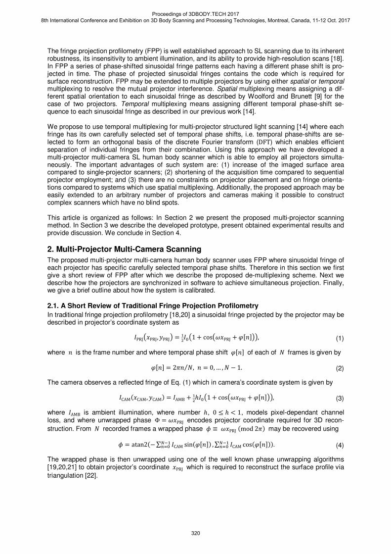
One necessary prerequisite for simultaneous projection is synchronization of projectors and cameras. The synchronization may be implemented in hardware or in software. Hardware implementations use custom synchronization circuits [24,25] or standard video-genlocks [26,27] while software implemen-tation relay on the precise timing of projection and acquisition [28]. We propose to use software only synchronization which is based on our previous work [28] where a VBLANK interrupt is used as a master timing signal to synchronize one or more cameras to a single projector. One challenge when extending our software-base synchronization [28] to multiple projectors is that each projector will have its own VBLANK interrupt. In other words on consumer grade video graphics cards VBLANK interrupt for each output occurs at different time as video output ports are not synchronized; exceptions are synchronized display solutions intended for large-scale video walls such as NVidia’s Quadro Sync [29]. To synchronize projectors in software, additional overhead delays will be included into the scheme of [28] to achieve the following: (1) new frames may be presented by each projector only after all cameras have completed acquisition, and (2) no camera may be triggered be-fore the delay time of the slowest projector has expired. A timing diagram showing the proposed software synchronization scheme for a simple two-projectors two-cameras scanner is shown in Fig. 1. The maximum achievable acquisition frame rate when using the proposed software synchronization scheme is
A�� = 2&@ ⁄ , = 0, … , − 1 and @ = 0, … , � − 1
≥ 2� + 1
�CAM = �AMB + 9:
∑ ℎA�A!1 + cos!�A�A + A��''�1�A34 ,
Proceedings of 3DBODY.TECH 2017 8th International Conference and Exhibition on 3D Body Scanning and Processing Technologies, Montreal, Canada, 11-12 Oct. 2017
321
(8)
where CD,max is the delay time of the slowest projector, CF is the camera exposure time, CG is the
frame readout and data transfer time, and CH is the unavoidable overhead time
Figure 1. Timing diagram for software synchronization of two-projector two-camera 3D scanner. Note that PRJ1 is the slowest projector.
2.4. System Calibration
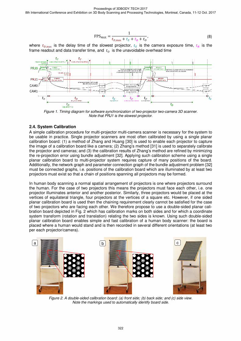
A simple calibration procedure for multi-projector multi-camera scanner is necessary for the system to be usable in practice. Single projector scanners are most often calibrated by using a single planar calibration board: (1) a method of Zhang and Huang [30] is used to enable each projector to capture the image of a calibration board like a camera; (2) Zhang’s method [31] is used to separately calibrate the projector and cameras; and (3) the calibration results of Zhang’s method are refined by minimizing the re-projection error using bundle adjustment [32]. Applying such calibration scheme using a single planar calibration board to multi-projector system requires capture of many positions of the board. Additionally, the network graph and parameter connection graph of the bundle adjustment problem [32] must be connected graphs, i.e. positions of the calibration board which are illuminated by at least two projectors must exist so that a chain of positions spanning all projectors may be formed. In human body scanning a normal spatial arrangement of projectors is one where projectors surround the human. For the case of two projectors this means the projectors must face each other, i.e. one projector illuminates anterior and another posterior. Similarly, three projectors would be placed at the vertices of equilateral triangle, four projectors at the vertices of a square etc. However, if one sided planar calibration board is used then the chaining requirement clearly cannot be satisfied for the case of two projectors who are facing each other. We therefore propose to use a double-sided planar cali-bration board depicted in Fig. 2 which has calibration marks on both sides and for which a coordinate system transform (rotation and translation) relating the two sides is known. Using such double-sided planar calibration board enables simple and fast calibration of a human body scanner: the board is placed where a human would stand and is then recorded in several different orientations (at least two per each projector/camera).
Figure 2. A double-sided calibration board: (a) front side; (b) back side; and (c) side view. Note the markings used to automatically identify board side.
FPSMAX =1
CD,max + CF + CG + CH,
a b c
Proceedings of 3DBODY.TECH 2017 8th International Conference and Exhibition on 3D Body Scanning and Processing Technologies, Montreal, Canada, 11-12 Oct. 2017
322
3. Results and Discussion
3.1. Prototype
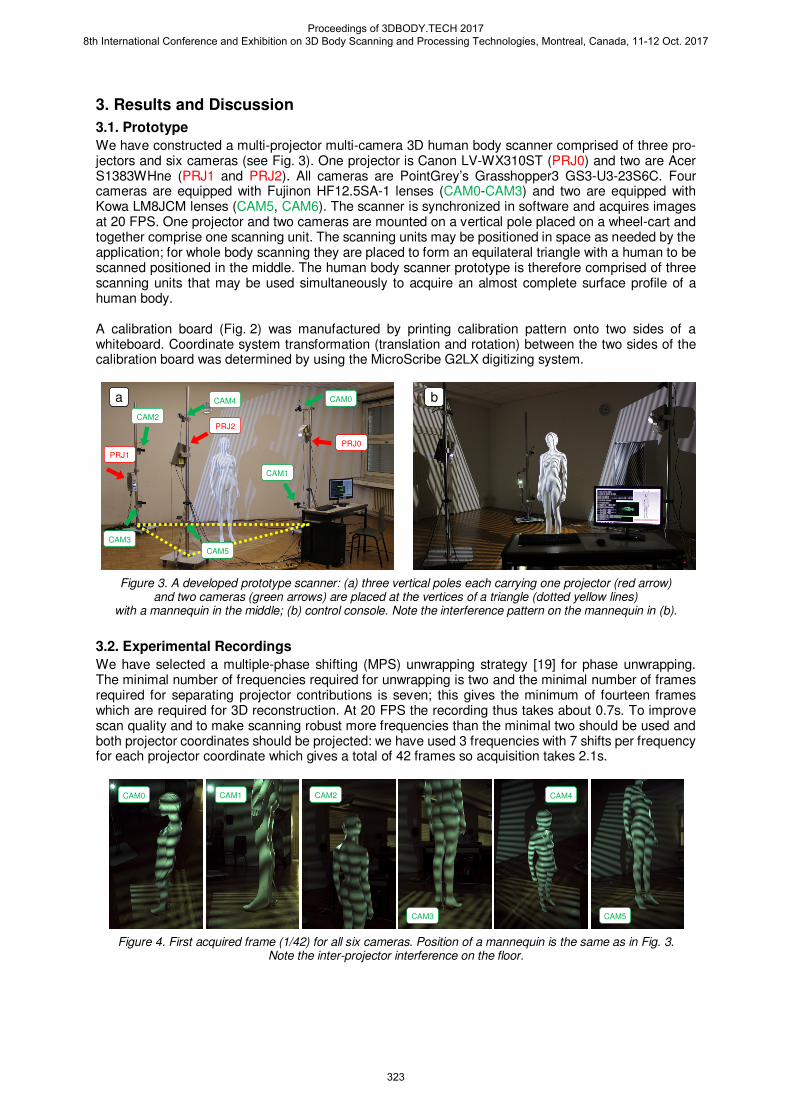
We have constructed a multi-projector multi-camera 3D human body scanner comprised of three pro-jectors and six cameras (see Fig. 3). One projector is Canon LV-WX310ST (PRJ0) and two are Acer S1383WHne (PRJ1 and PRJ2). All cameras are PointGrey’s Grasshopper3 GS3-U3-23S6C. Four cameras are equipped with Fujinon HF12.5SA-1 lenses (CAM0-CAM3) and two are equipped with Kowa LM8JCM lenses (CAM5, CAM6). The scanner is synchronized in software and acquires images at 20 FPS. One projector and two cameras are mounted on a vertical pole placed on a wheel-cart and together comprise one scanning unit. The scanning units may be positioned in space as needed by the application; for whole body scanning they are placed to form an equilateral triangle with a human to be scanned positioned in the middle. The human body scanner prototype is therefore comprised of three scanning units that may be used simultaneously to acquire an almost complete surface profile of a human body. A calibration board (Fig. 2) was manufactured by printing calibration pattern onto two sides of a whiteboard. Coordinate system transformation (translation and rotation) between the two sides of the calibration board was determined by using the MicroScribe G2LX digitizing system.
Figure 3. A developed prototype scanner: (a) three vertical poles each carrying one projector (red arrow) and two cameras (green arrows) are placed at the vertices of a triangle (dotted yellow lines)
with a mannequin in the middle; (b) control console. Note the interference pattern on the mannequin in (b).
3.2. Experimental Recordings
We have selected a multiple-phase shifting (MPS) unwrapping strategy [19] for phase unwrapping. The minimal number of frequencies required for unwrapping is two and the minimal number of frames required for separating projector contributions is seven; this gives the minimum of fourteen frames which are required for 3D reconstruction. At 20 FPS the recording thus takes about 0.7s. To improve scan quality and to make scanning robust more frequencies than the minimal two should be used and both projector coordinates should be projected: we have used 3 frequencies with 7 shifts per frequency for each projector coordinate which gives a total of 42 frames so acquisition takes 2.1s.
Figure 4. First acquired frame (1/42) for all six cameras. Position of a mannequin is the same as in Fig. 3. Note the inter-projector interference on the floor.
a b
CAM0 CAM1 CAM2
CAM3
CAM4
CAM5
CAM0
CAM1
CAM2
CAM4
CAM3
CAM5
PRJ0
PRJ1
PRJ2
Proceedings of 3DBODY.TECH 2017 8th International Conference and Exhibition on 3D Body Scanning and Processing Technologies, Montreal, Canada, 11-12 Oct. 2017
323
CAM0 CAM1 illuminated projector column projector row illuminated projector column projector row
PR
J0
PR
J1
PR
J2
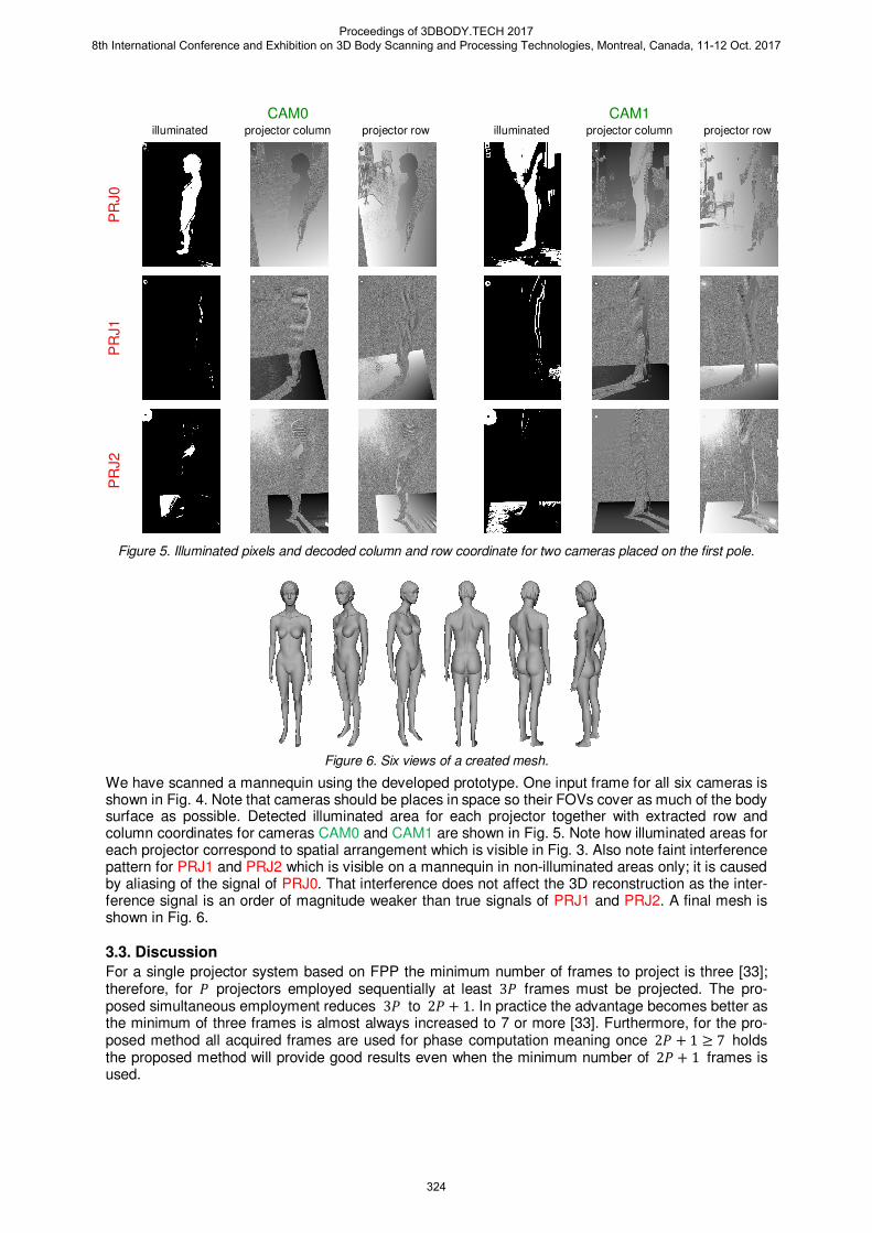
Figure 5. Illuminated pixels and decoded column and row coordinate for two cameras placed on the first pole.
Figure 6. Six views of a created mesh.
We have scanned a mannequin using the developed prototype. One input frame for all six cameras is shown in Fig. 4. Note that cameras should be places in space so their FOVs cover as much of the body surface as possible. Detected illuminated area for each projector together with extracted row and column coordinates for cameras CAM0 and CAM1 are shown in Fig. 5. Note how illuminated areas for each projector correspond to spatial arrangement which is visible in Fig. 3. Also note faint interference pattern for PRJ1 and PRJ2 which is visible on a mannequin in non-illuminated areas only; it is caused by aliasing of the signal of PRJ0. That interference does not affect the 3D reconstruction as the inter-ference signal is an order of magnitude weaker than true signals of PRJ1 and PRJ2. A final mesh is shown in Fig. 6.
3.3. Discussion
For a single projector system based on FPP the minimum number of frames to project is three [33]; therefore, for � projectors employed sequentially at least 3� frames must be projected. The pro-posed simultaneous employment reduces 3� to 2� + 1. In practice the advantage becomes better as the minimum of three frames is almost always increased to 7 or more [33]. Furthermore, for the pro-posed method all acquired frames are used for phase computation meaning once 2� + 1 ≥ 7 holds the proposed method will provide good results even when the minimum number of 2� + 1 frames is used.
Proceedings of 3DBODY.TECH 2017 8th International Conference and Exhibition on 3D Body Scanning and Processing Technologies, Montreal, Canada, 11-12 Oct. 2017
324

A disadvantage of the proposed method compared to sequential projector employment is sharing of the dynamic range between projectors. For sequential employment whole dynamic range of each camera may be allocated to a single projector, however for simultaneous employment dynamic range must be divided between � projectors. This reduction in dynamic range increases the measurement noise and may affect wrapped phase estimation. This negative effect may be mitigated by using a camera with better bit depth or by simply increasing the number of acquired frames from the minimal 2� + 1. For surround projector setup which is used in human body scanning this effect may be further reduced if the number of projectors with an overlapping FOV is less than the total number of projectors: the dynamic range is shared only between projectors with an overlapping FOV. The proposed method places no restrictions on the spatial arrangement of cameras and projectors. We have used this fact in the design of our prototype scanner which is comprised of three scanning units which provide a significant freedom when using the prototype scanner: scanning units may be spatially rearranged to achieve the best coverage of a body part to be recorded. Once units are posi-tioned as needed the calibration is simply done by recording the double-sided calibration board in at least two positions per projector/camera. For a three-projector six-camera system this means at least 18 positions of the calibration board must be recorded. Since a recording of one position of the cali-bration board takes 2.1s, calibration data is collected in a few minutes.
4. Conclusion
We have developed a prototype 3D human body scanner comprised of three projectors and six cam-eras which enables simultaneous projector employment. The simultaneous employment is possible due to a careful choice of temporal phase shifts for each projector so they together comprise a DFT���� basis which in turn enables simple and efficient separation of the combined patterns into the contributions of each projector simply by applying the fast Fourier transform algorithm. The proposed method places no constraints on the number of projectors or on their spatial arrange-ment. Coupled with a simple and fast calibration procedure this provides flexibility in scanning and enables construction of large FPP scanners which use many projectors and cameras.
Acknowledgment
This work was supported by the Croatian Science Foundation under Project IP-11-2013-3717.
References
[1] Jason Geng, “Structured-light 3D surface imaging: a tutorial”, in Advances in Optics and Photonics, Vol. 3, No. 2, 2011, pp. 128-160, http://dx.doi.org/10.1364/AOP.3.000128
[2] Joaquim Salvi, Sergio Fernandez, Tomislav Pribanić, Xavier Llado, “A state of the art in structured light pat-terns for surface profilometry”, in Pattern Recognition, Vol. 43, No. 8, August 2010, pp. 2666-2680, http://dx.doi.org/10.1016/j.patcog.2010.03.004
[3] Joaquim Salvi, Jordi Pagès, Joan Batlle, “Pattern codification strategies in structured light systems”, in Pat-tern Recognition, Vol. 37, No. 4, April 2004, pp. 827-849, http://dx.doi.org/10.1016/j.patcog.2003.10.002
[4] J. Battle, E. Mouaddib, J. Salvi, “Recent progress in coded structured light as a technique to solve the cor-respondence problem: a survey”, in Pattern Recognition, Vol. 31, No. 7, July 1998, pp. 963-982
[5] Z. H. Zhang, “Review of single-shot 3D shape measurement by phase calculation-based fringe projection techniques”, in Optics and Lasers in Engineering, Vol. 50, No. 8, August 2012, pp. 1097-1106, http://dx.doi.org/10.1016/j.optlaseng.2012.01.007
[6] Ricardo R. Garcia, Avideh Zakhor, “Markerless Motion Capture with Multi-view Structured Light”, in Electronic Imaging, Feburary 2014, pp. 3DIPM-050.1-3DIPM-050.7, http://dx.doi.org/10.2352/ISSN.2470-1173.2016.21.3DIPM-050
[7] Ricardo R. Garcia, Avideh Zakhor, “Geometric calibration for a multi-camera-projector system”, in 2013 IEEE Workshop on Applications of Computer Vision (WACV), Tampa, Florida, January 15-17, 2013, pp. 467-474, http://dx.doi.org/10.1109/WACV.2013.6475056
[8] Wei-Hung Su, Cho-Yo Kuo, Chun-Chieh Wang, Chung-Fan Tu, “Projected fringe profilometry with multiple measurements to form an entire shape”, in Optics Express, Vol. 16, No. 6, 2008, pp. 4069-4077, http://dx.doi.org/10.1364/OE.16.004069
[9] Stuart Woolford, Ian S. Burnett, “Toward a one shot multi-projector profilometry system for full field of view object measurement”, in 2014 IEEE International Conference on Acoustics, Speech and Signal Processing (ICASSP), Florence, Italy, May 4-9, 2014, pp. 569-573, http://dx.doi.org/10.1109/ICASSP.2014.6853660
Proceedings of 3DBODY.TECH 2017 8th International Conference and Exhibition on 3D Body Scanning and Processing Technologies, Montreal, Canada, 11-12 Oct. 2017
325

[10] Changsoo Je, Kwang Hee Lee, Sang Wook Lee, “Multi-projector color structured-light vision”, in Signal Pro-cessing: Image Communication, Vol. 28, No. 9, October 2013, pp. 1046-1058, http://dx.doi.org/10.1016/j.image.2013.05.005
[11] Ryusuke Sagawa, Ryo Furukawa, Hiroshi Kawasaki, “Dense 3D Reconstruction from High Frame-Rate Video Using a Static Grid Pattern”, in IEEE Transactions on Pattern Analysis and Machine Intelligence, Vol. 36, No. 9, September 2014, pp. 1733-1747, http://dx.doi.org/10.1109/TPAMI.2014.2300490
[12] Ryo Furukawa, Ryusuke Sagawa, Amael Delaunoy, Hiroshi Kawasaki, “Multiview projectors/cameras system for 3D reconstruction of dynamic scenes”, in 2011 IEEE International Conference on Computer Vision Workshops (ICCV Workshops), Barcelona, 2011, pp. 1602-1609, http://dx.doi.org/10.1109/ICCVW.2011.6130441
[13] Ryo Furukawa, Ryusuke Sagawa, Hiroshi Kawasaki, Kazuhiro Sakashita, Yasushi Yagi, Naoki Asada, “One-shot Entire Shape Acquisition Method Using Multiple Projectors and Cameras”, in 2010 Fourth Pacif-ic-Rim Symposium on Image and Video Technology, Singapore, 2010, pp. 107-114, http://dx.doi.org/10.1109/PSIVT.2010.25
[14] Tomislav Petković, Tomislav Pribanić, Matea Đonlić, Peter Sturm, "Efficient Separation between Projected Patterns for Multiple Projector 3D People Scanning", accepted for 2011 IEEE International Conference on Computer Vision Workshops (ICCV Workshops), Venice, October 22-29, 2017
[15] Zengqiang Yan, Li Yu, You Yang, and Qiong Liu, “Beyond the interference problem: hierarchical patterns for multiple-projector structured light system”, in Applied Optics, Vol. 53, No. 17, 2014, pp. 3621-3632, http://dx.doi.org/10.1364/AO.53.003621
[16] M. Servin, G. Garnica, J. C. Estrada, A. Quiroga, “Coherent digital demodulation of single-camera N-projections for 3D-object shape measurement: Co-phased profilometry”, in Optics Express, Vol. 21, No. 21, 2013, pp. 24873-24878, http://dx.doi.org/10.1364/OE.21.024873
[17] Tong Jia, BingNan Wang, ZhongXuan Zhou, Haixiu Meng, “Scene Depth Perception Based on Omnidirec-tional Structured Light," in IEEE Transactions on Image Processing, Vol. 25, No. 9, September 2016, pp. 4369-4378, http://dx.doi.org/10.1109/TIP.2016.2590304
[18] Sai Siva Gorthi, Pramod Rastogi, “Fringe projection techniques: Whither we are?”, in Optics and Lasers in Engineering, Vol. 48, No. 2, Feburary 2010, pp. 133-140, http://dx.doi.org/10.1016/j.optlaseng.2009.09.001
[19] Tomislav Petković, Tomislav Pribanić, Matea Đonlić, “Temporal phase unwrapping using orthographic pro-jection”, in Optics and Lasers in Engineering, Vol. 90, 2017, pp. 34-47, http://dx.doi.org/10.1016/j.optlaseng.2016.09.006
[20] Chao Zuo, Lei Huang, Minliang Zhang, Qian Chen, Anand Asundi, “Temporal phase unwrapping algorithms for fringe projection profilometry: A comparative review”, in Optics and Lasers in Engineering, Vol. 85, Octo-ber 2016, pp. 84-103, http://dx.doi.org/10.1016/j.optlaseng.2016.04.022
[21] D. C. Ghiglia, M. D. Pritt, “Two Dimensional Phase Unwrapping: Theory, Algorithms, and Software”, Wiley, May 1998
[22] R. Hartley, A. Zisserman, “Multiple view geometry in computer vision”, Cambrige University Press, 2003 [23] S. K. Mitra, “Digital Signal Processing: A Computer-Based Approach”, McGraw-Hill Compaines, 3rd edition,
January 2005 [24] Song Zhang, “High-resolution, Real-time 3-D Shape Measurement”, Doctoral Dissertation, Stony Brook Uni-
versity, May 2005 [25] Joji Takei, Shingo Kagami, Koichi Hashimoto, “3000-fps 3-D Shape Measurement Using a High-Speed
Camera-Projector System”, in Proceedings of the 2007 IEEE/RSJ International Conference on Intelligent Robots and Systems, San Diego, CA, USA, October 29-November 2, 2007, pp. 3211-3216, http://dx.doi.org/10.1109/IROS.2007.4399626
[26] Kovacs J., “An Overview of Genlock”, Application Note No.5, MicroImage Video Systems, [Online], Available http://www.mivs.com/documents/application-notes/an005-application-note/
[27] Szymon Rusinkiewicz, Olaf Hall-Holt, Marc Levoy, “Real-time 3D model acquisition”, in Proceedings of the 29th annual conference on Computer graphics and interactive techniques SIGGRAPH ’02, San Antonio, Texas, USA, July 21-26, 2002, pp. 438-446, http://dx.doi.org/10.1145/566570.566600
[28] T. Petković, T. Pribanić, M. Đonlić, N. D'Apuzzo, “Software Synchronization of Projector and Camera for Structured Light 3D Body Scanning”, in Proc. of 7th Int. Conf. on 3D Body Scanning Technologies, Lugano, Switzerland, 2016, pp. 286-295, http://dx.doi.org/10.15221/16.286
[29] NVidia, “NVidia Quadro Sync”, [Online], Available http://www.nvidia.com/object/quadro-sync.html [30] Song Zhang, Peisen S. Huang, “Novel method for structured light system calibration”, in Optical Engineering,
Vol. 45, No. 8, August 2006, http://dx.doi.org/10.1117/1.2336196 [31] Z. Zhang, “A flexible new technique for camera calibration”, in IEEE Transactions on Pattern Analysis and
Machine Intelligence, Vol. 22, No. 11, pp. 1330-1334, November 2000, http://dx.doi.org/10.1109/34.888718 [32] Bill Triggs, Philip F. McLauchlan, Richard I. Hartley, Andrew W. Fitzgibbon, “Bundle Adjustment—A Modern
Synthesis”, in International Workshop on Vision Algorithms IWVA 1999: Vision Algorithms: Theory and Prac-tice, pp. 298-372, http://dx.doi.org/10.1007/3-540-44480-7_21
[33] Peter de Groot, “Derivation of algorithms for phase-shifting interferometry using the concept of a da-ta-sampling window”, in Applied Optics, Vol. 34, No. 22, 1995, pp. 4723-4730, http://dx.doi.org/10.1364/AO.34.004723
Proceedings of 3DBODY.TECH 2017 8th International Conference and Exhibition on 3D Body Scanning and Processing Technologies, Montreal, Canada, 11-12 Oct. 2017
326