Embed Size (px)
Citation preview
MULTI-MEDIA PROJECTOR – SINGLE CAMERA PHOTOGRAMMETRIC SYSTEM FOR FAST 3D RECONSTRUCTION
V. A. Knyaz *
State Research Institute of Aviation System (GosNIIAS), 125319 Moscow, Russia – [email protected]
Commission V, WG V/4
KEY WORDS: Photogrammetry, Calibration, Texturing, Accuracy, Multi-media projector, Automation ABSTRACT: Some of the important technical characteristics of photogrammetric system are the speed of 3D acquisition, automation and possibility for smart operating. Using structured and coded light allows to solve correspondence problem fast, robustly and accurate. And applying of PC-controlled structured light provides a possibility to make a step to highly automated and intellectual photogrammetric systems. Multi-media projectors have a number of features which make them attractive for using in photogrammetric application. The main of these features are high technical characteristics (such as brightness, contrast, signal/noise ratio, resolution) and a reasonable price. And the main advantage of digital projector is a capability of smart lighting for applying smart processing algorithms. A traditional configuration of a close range photogrammetric system usually includes two calibrated cameras and a structured light projector, which has no need to be calibrated. If color texturing is needed additional color camera is applied. Using PC-controlled multi-media calibrated projector allows to increase productivity of a 3D reconstruction system and to reduce its cost due to including only one monochrome camera. Techniques for projector calibration and for 3D model color texturing are developed. Projector calibration is based on standard bundle adjustment technique traditionally used for camera calibration. The first approach uses two calibrated cameras for producing “virtual” spatial test field. The second method supposes generating synthetic “images” of a test field observed by the projector. Then the parameters of interior orientation for the camera and the projector are found by standard bundle adjustment procedure. 3D model color texturing performed by a set of monochrome images processing obtained in projector lighting.
* 7, Victorenko str. Moscow, Russia 125319. Phone: +7 499 157 3127, Fax: +7 499 943 8605, e-mail: [email protected]
1. INTRODUCTION
Application of structured light projector in a photogrammetric system allows solving correspondence problem fully automatically, robustly and with high accuracy because any point lighted by a projector could be easily identified on each image used for 3D reconstruction. To provide accurate spatial coordinate measuring the geometry of image acquisition (image interior and exterior orientation) should be known. For close range systems image orientation is usually determined by preliminary cameras calibration using special test fields. Then spatial coordinate determination is solved as intersection problem with known parameters for both cameras. Modern digital projectors have high technical characteristics such as resolution, frequency, brightness, contrast which make them attractive for 3D reconstruction application. The projection system of a projector could be described similar to a camera, so a projector could be concerned as inverse camera which does not acquire but create central projection image. So if parameters of projected image were known spatial coordinates of any lighted point could be found. Concerning projector as inverse camera allows eliminating one camera from traditional setup thus increasing speed of 3D acquisition and simplifying the system. There are two common approaches for a projector calibration. The first one is based on estimation of the parameters for each light stripe plane generated by projector.
The second approach is to consider a projector as an inverse camera and to calibrate it similar to camera calibration. A set of reference 3D points and corresponding 2D observations of these 3D points is needed to estimate projector model parameters. The most sophisticated task is to measure spatial reference points for a projected pattern. Some solutions for this problem were proposed. To apply two or more target points for each light beam for estimating the parameters of the light beams by a 3D line-fitting algorithm is proposed (Shen, 2000). A high precision calibration plane is placed in sequence at distinct depths along the light beam direction and its position and orientation are measured by the coordinate measuring machine (CMM). By projecting the light beams on the calibration plane, points in a grid are formed and their 3D coordinates can be calculated for determining the parameters of the light beams. Another approach (Gao, 2007) uses a calibration board with circular control points printed on a laser printer. A reference pattern with some horizontal red stripes and one green stripe is projected onto the surface plane by a LCD projector. Based on the cross ratio and the epipolar geometry, the 2D-3D point pairs for the projector and camera are obtained. A technique with two joint test fields (one for a camera, another for a projector) was proposed (Sadlo, 2005). A calibration pattern in form chess-board was projected on a plane with
International Archives of Photogrammetry, Remote Sensing and Spatial Information Sciences, Vol. XXXVIII, Part 5 Commission V Symposium, Newcastle upon Tyne, UK. 2010
343
similar calibration pattern printed on this plane. Printed pattern with known reference point is used for plane orientation estimation, so spatial coordinates of projected pattern can be found. Some techniques (Drouin, 2008) use calibration pattern to take only one view by a set of cameras. Energy formulation is used for simplifying a process of determining correspondences. Also partially calibrated camera can be used for projector calibration (Drareni, 2009). The problem of determining the world-camera homography is solved by searching the one which minimize the re-projection error. The general concept of proposed approach for projector calibration is to widely use means for reference point’s identification and measurement previously developed for camera calibration. So projector images of test field are to be captured. The technique for projector image capturing is developed and implemented. Another attractive property of multimedia projector is the ability of programmable color lighting. It is used for generating color texture for reconstructed object using monochrome camera included in the system. To obtain color realistic texture a special color calibration procedure is developed.
2. SYSTEM CONFIGURATION
2.1 System outline
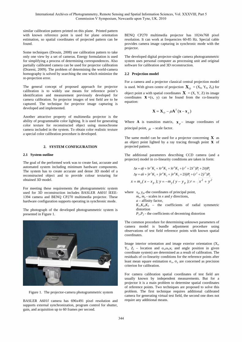
The goal of the performed work was to create fast, accurate and automated system including minimum hardware components. The system has to create accurate and dense 3D model of a reconstructed object and to provide colour texturing for obtained 3D model. For meeting these requirements the photogrammetric system used for 3D reconstruction includes BASLER A601f IEEE-1394 camera and BENQ CP270 multimedia projector. These hardware configuration supports operating in synchronic mode. The photograph of the developed photogrammetric system is presented in Figure 1.
Figure 1. The projector-camera photogrammetric system BASLER A601f camera has 696x491 pixel resolution and supports external synchronization, program control for shutter, gain, and acquisition up to 60 frames per second.
BENQ CP270 multimedia projector has 1024x768 pixel resolution. It can work at frequencies 60-85 Hz. Special cable provides camera image capturing in synchronic mode with the projector. The developed digital projector-single camera photogrammetric system uses personal computer as processing unit and original software for calibration and 3D reconstruction. 2.2 Projection model
For a camera and a projector classical central projection model is used. With given centre of projection OX = (X0, Y0, Z0) for
object point a with spatial coordinates X = (X, Y, Z) its image coordinates x =(x, y) can be found from the co-linearity equation:
)( pT
O xxAXX −−= μ
Where A is transition matrix, px – image coordinates of
principal point, μ – scale factor. The same model can be used for a projector concerning X as an object point lighted by a ray tracing through point x of projected pattern. The additional parameters describing CCD camera (and a projector) model in co-linearity conditions are taken in form:
222
136
24
12
2122
36
24
12
)2(2
2)2(
PyrPyxKryKryKryxay
PyxPxrKrxKrxKrxyax
++++++=Δ
++++++=Δ
22pypx yxr);yy(my);xx(mx +=−−=−=
where xp, yp,-the coordinates of principal point,
mx, my - scales in x and y directions, a – affinity factor, K1,K2,K3 – the coefficients of radial symmetric distortion P1,P2 - the coefficients of decentring distortion
The common procedure for determining unknown parameters of camera model is bundle adjustment procedure using observations of test field reference points with known spatial coordinates. Image interior orientation and image exterior orientation (Xi, Yi, Zi – location and αi,ωi,κi and angle position in given coordinate system) are determined as a result of calibration. The residuals of co-linearity conditions for the reference points after least mean square estimation σx, σy are concerned as precision criterion for calibration. For camera calibration spatial coordinates of test field are usually known by independent measurements. But for a projector it is a main problem to determine spatial coordinates of reference points. Two techniques are proposed to solve this problem. The first technique requires additional calibrated camera for generating virtual test field, the second one does not require any additional means.
International Archives of Photogrammetry, Remote Sensing and Spatial Information Sciences, Vol. XXXVIII, Part 5 Commission V Symposium, Newcastle upon Tyne, UK. 2010
344
3. PROJECTOR CALBRATION BY VIRTUAL 3D TEST FIELD
First method for multimedia projector calibration uses two calibrated cameras for creating virtual spatial test field for projector interior orientation parameters estimation. 3.1 Virtual 3D test field generating
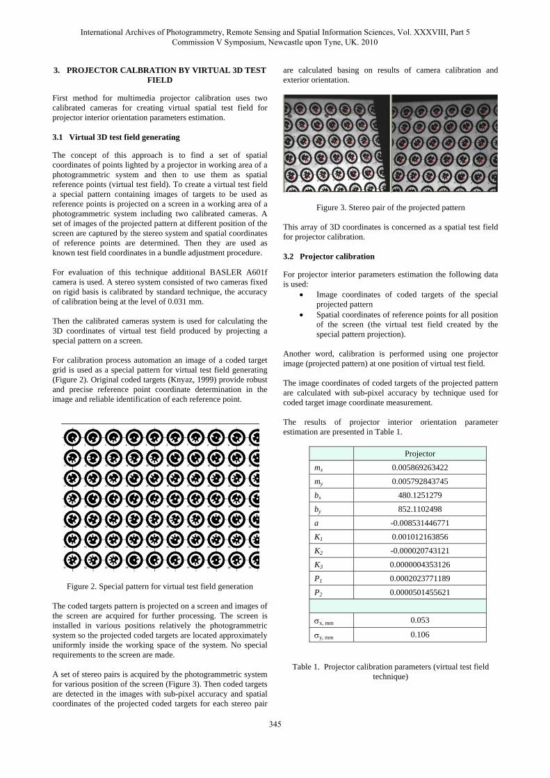
The concept of this approach is to find a set of spatial coordinates of points lighted by a projector in working area of a photogrammetric system and then to use them as spatial reference points (virtual test field). To create a virtual test field a special pattern containing images of targets to be used as reference points is projected on a screen in a working area of a photogrammetric system including two calibrated cameras. A set of images of the projected pattern at different position of the screen are captured by the stereo system and spatial coordinates of reference points are determined. Then they are used as known test field coordinates in a bundle adjustment procedure. For evaluation of this technique additional BASLER A601f camera is used. A stereo system consisted of two cameras fixed on rigid basis is calibrated by standard technique, the accuracy of calibration being at the level of 0.031 mm. Then the calibrated cameras system is used for calculating the 3D coordinates of virtual test field produced by projecting a special pattern on a screen. For calibration process automation an image of a coded target grid is used as a special pattern for virtual test field generating (Figure 2). Original coded targets (Knyaz, 1999) provide robust and precise reference point coordinate determination in the image and reliable identification of each reference point.
Figure 2. Special pattern for virtual test field generation The coded targets pattern is projected on a screen and images of the screen are acquired for further processing. The screen is installed in various positions relatively the photogrammetric system so the projected coded targets are located approximately uniformly inside the working space of the system. No special requirements to the screen are made. A set of stereo pairs is acquired by the photogrammetric system for various position of the screen (Figure 3). Then coded targets are detected in the images with sub-pixel accuracy and spatial coordinates of the projected coded targets for each stereo pair
are calculated basing on results of camera calibration and exterior orientation.
Figure 3. Stereo pair of the projected pattern This array of 3D coordinates is concerned as a spatial test field for projector calibration. 3.2 Projector calibration
For projector interior parameters estimation the following data is used:
• Image coordinates of coded targets of the special projected pattern
• Spatial coordinates of reference points for all position of the screen (the virtual test field created by the special pattern projection).
Another word, calibration is performed using one projector image (projected pattern) at one position of virtual test field. The image coordinates of coded targets of the projected pattern are calculated with sub-pixel accuracy by technique used for coded target image coordinate measurement. The results of projector interior orientation parameter estimation are presented in Table 1.
Projector
mx 0.005869263422
my 0.005792843745
bx 480.1251279
by 852.1102498
a -0.008531446771
K1 0.001012163856
K2 -0.000020743121
K3 0.0000004353126
P1 0.0002023771189
P2 0.0000501455621
σx, mm 0.053
σy, mm 0.106
Table 1. Projector calibration parameters (virtual test field technique)
International Archives of Photogrammetry, Remote Sensing and Spatial Information Sciences, Vol. XXXVIII, Part 5 Commission V Symposium, Newcastle upon Tyne, UK. 2010
345
For projector exterior orientation parameters determination the same virtual test field is used. It gives exterior orientation parameters in the same coordinate system as the cameras because the reference points the virtual test field are given in the real test field coordinate system.
4. PROJECTOR CALBRATION USING “IMAGES” FROM PROJECTOR
The second approach for a projector calibration is to find projector 2D coordinates for known spatial references points of a test field. This problem is solved by generating synthetic image of a scene lighted (“observed”) by a projector. For creating these images the CCD camera of the system is used. 4.1 Projector “image” generating
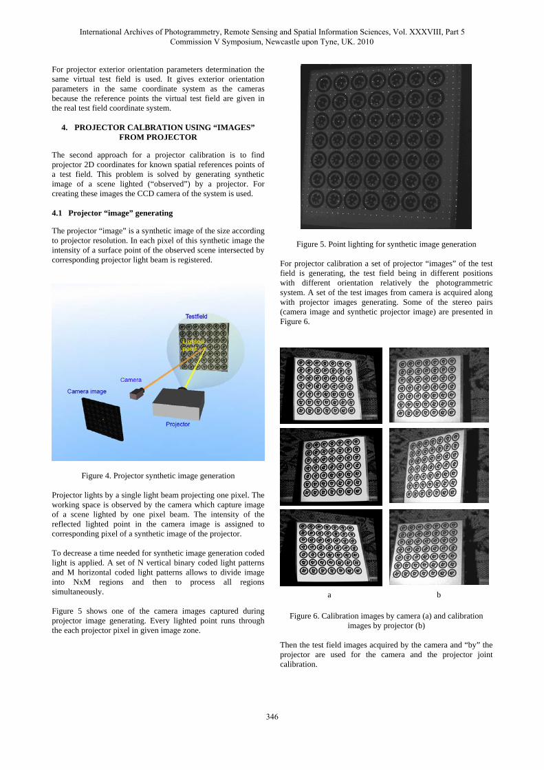
The projector “image” is a synthetic image of the size according to projector resolution. In each pixel of this synthetic image the intensity of a surface point of the observed scene intersected by corresponding projector light beam is registered.
Figure 4. Projector synthetic image generation Projector lights by a single light beam projecting one pixel. The working space is observed by the camera which capture image of a scene lighted by one pixel beam. The intensity of the reflected lighted point in the camera image is assigned to corresponding pixel of a synthetic image of the projector. To decrease a time needed for synthetic image generation coded light is applied. A set of N vertical binary coded light patterns and M horizontal coded light patterns allows to divide image into NxM regions and then to process all regions simultaneously. Figure 5 shows one of the camera images captured during projector image generating. Every lighted point runs through the each projector pixel in given image zone.
Figure 5. Point lighting for synthetic image generation For projector calibration a set of projector “images” of the test field is generating, the test field being in different positions with different orientation relatively the photogrammetric system. A set of the test images from camera is acquired along with projector images generating. Some of the stereo pairs (camera image and synthetic projector image) are presented in Figure 6.
a b
Figure 6. Calibration images by camera (a) and calibration
images by projector (b) Then the test field images acquired by the camera and “by” the projector are used for the camera and the projector joint calibration.
International Archives of Photogrammetry, Remote Sensing and Spatial Information Sciences, Vol. XXXVIII, Part 5 Commission V Symposium, Newcastle upon Tyne, UK. 2010
346
4.2 Projector calibration
For projector interior parameters estimation in this case the following data is used:
• Image coordinates of reference points of projector “images”
• Spatial coordinates of reference points of the test field Another word, calibration is performed using a set of projector synthetic images for various positions of the test field. The results of the projector and the camera interior orientation parameter estimation by described technique are presented in Table 3.
Projector Camera
mx 0.0058752925676 0.009528061795
my 0.0057688332885 0.009359561153
bx 482.6271194 304.305727
by 846.0884315 287.639085
a -0.0066801002681 -0.00617081250598
K1 0.0008712668686 0.001612895994563
K2 -0.0000182067918 0.000091961874578
K3 0.0000003182135 -0.000007424986745
P1 0.0002827451789 -0.000030034268518
P2 0.0000445912586 0.000143368648668
σx, mm 0.025
σy, mm 0.024
Table 2. Projector calibration parameters (projector “image” technique)
The results of projector calibration by both developed techniques are in a good agreement. Both calibration approaches give the similar values for camera model parameters. The second technique (generating synthetic projector images) gives the better characteristics of the calibration σx, σy because of better image resolution (and therefore better accuracy of coordinates measurement).
5. COLOR TEXTURE GENERATION
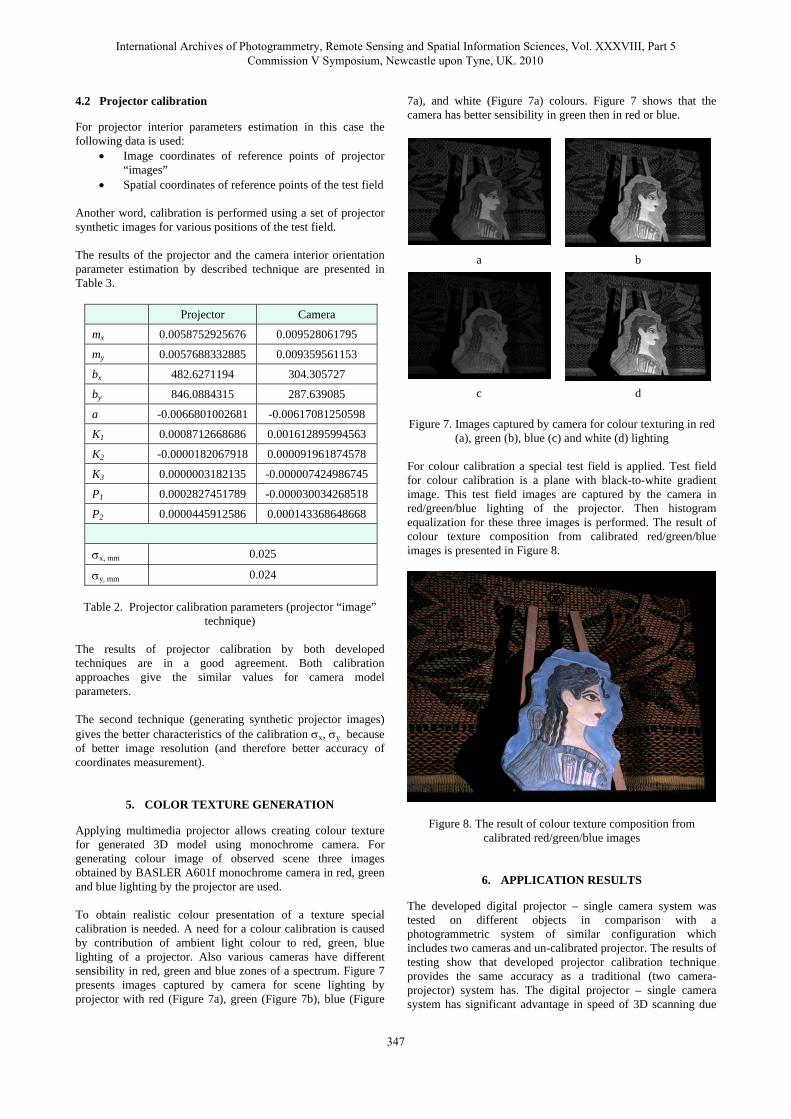
Applying multimedia projector allows creating colour texture for generated 3D model using monochrome camera. For generating colour image of observed scene three images obtained by BASLER A601f monochrome camera in red, green and blue lighting by the projector are used. To obtain realistic colour presentation of a texture special calibration is needed. A need for a colour calibration is caused by contribution of ambient light colour to red, green, blue lighting of a projector. Also various cameras have different sensibility in red, green and blue zones of a spectrum. Figure 7 presents images captured by camera for scene lighting by projector with red (Figure 7a), green (Figure 7b), blue (Figure
7a), and white (Figure 7a) colours. Figure 7 shows that the camera has better sensibility in green then in red or blue.
a b
c d
Figure 7. Images captured by camera for colour texturing in red
(a), green (b), blue (c) and white (d) lighting For colour calibration a special test field is applied. Test field for colour calibration is a plane with black-to-white gradient image. This test field images are captured by the camera in red/green/blue lighting of the projector. Then histogram equalization for these three images is performed. The result of colour texture composition from calibrated red/green/blue images is presented in Figure 8.
Figure 8. The result of colour texture composition from calibrated red/green/blue images
6. APPLICATION RESULTS
The developed digital projector – single camera system was tested on different objects in comparison with a photogrammetric system of similar configuration which includes two cameras and un-calibrated projector. The results of testing show that developed projector calibration technique provides the same accuracy as a traditional (two camera-projector) system has. The digital projector – single camera system has significant advantage in speed of 3D scanning due
International Archives of Photogrammetry, Remote Sensing and Spatial Information Sciences, Vol. XXXVIII, Part 5 Commission V Symposium, Newcastle upon Tyne, UK. 2010
347
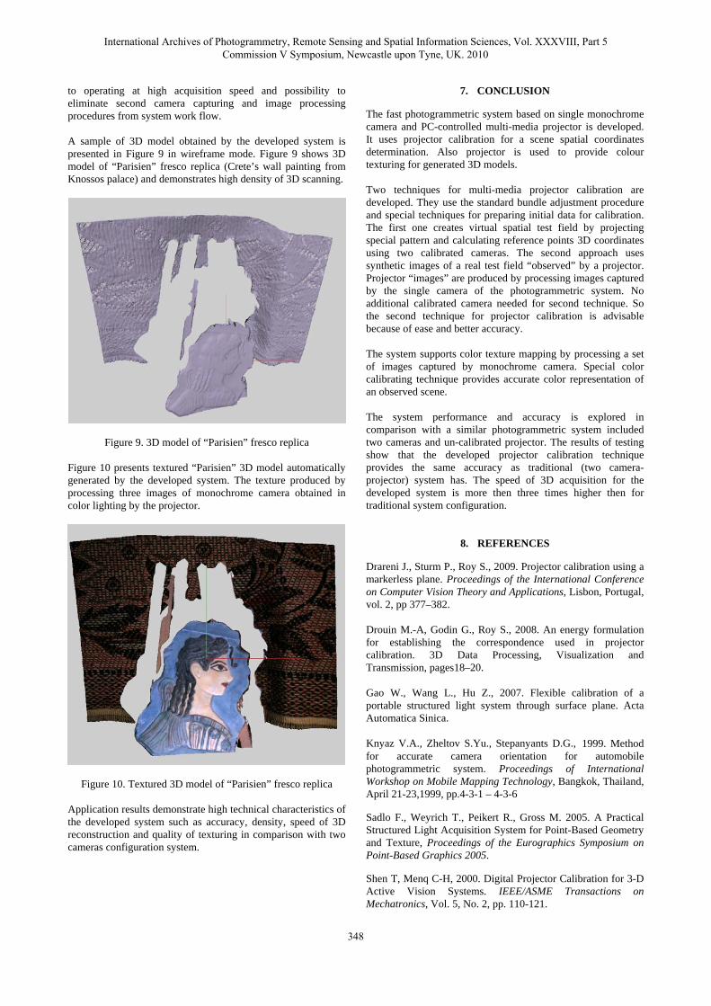
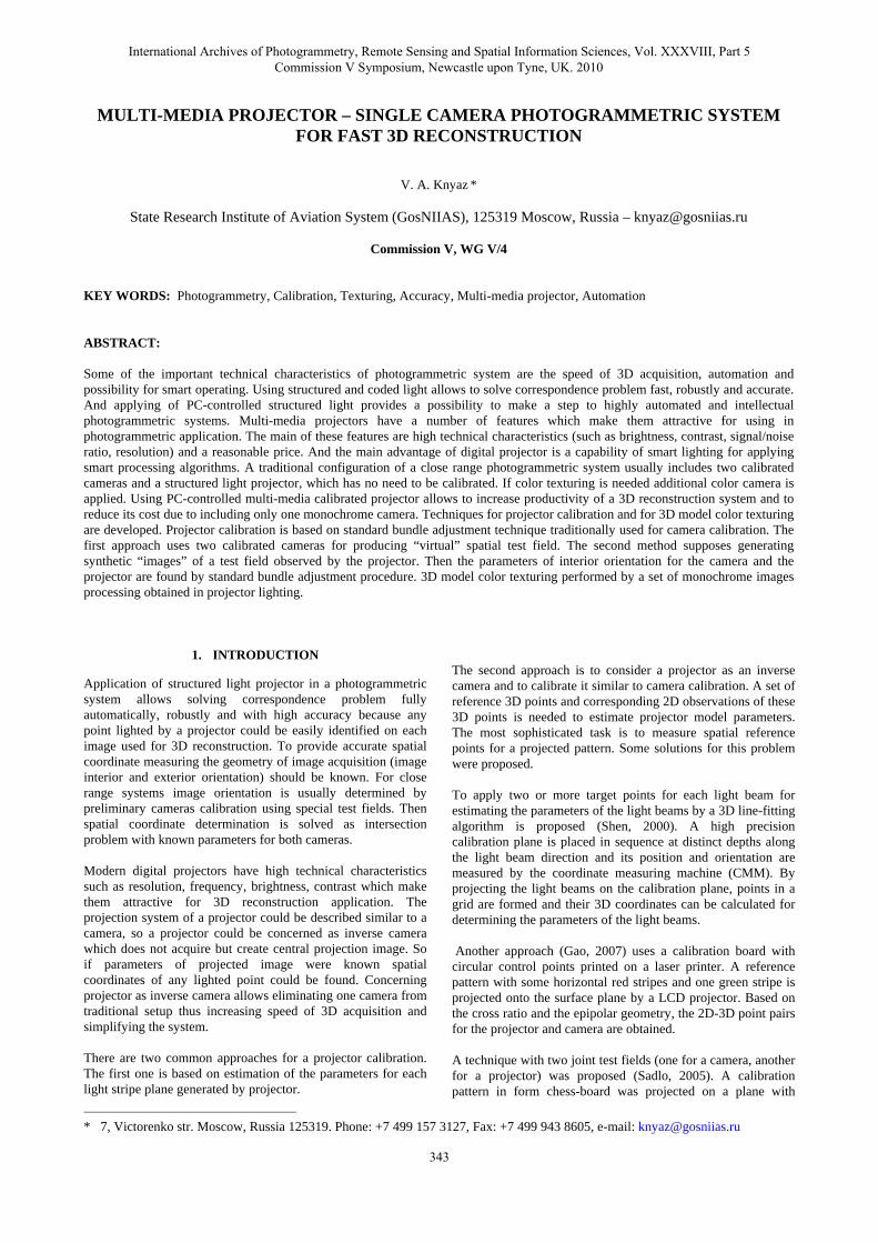
to operating at high acquisition speed and possibility to eliminate second camera capturing and image processing procedures from system work flow. A sample of 3D model obtained by the developed system is presented in Figure 9 in wireframe mode. Figure 9 shows 3D model of “Parisien” fresco replica (Crete’s wall painting from Knossos palace) and demonstrates high density of 3D scanning.
Figure 9. 3D model of “Parisien” fresco replica
Figure 10 presents textured “Parisien” 3D model automatically generated by the developed system. The texture produced by processing three images of monochrome camera obtained in color lighting by the projector.
Figure 10. Textured 3D model of “Parisien” fresco replica
Application results demonstrate high technical characteristics of the developed system such as accuracy, density, speed of 3D reconstruction and quality of texturing in comparison with two cameras configuration system.
7. CONCLUSION
The fast photogrammetric system based on single monochrome camera and PC-controlled multi-media projector is developed. It uses projector calibration for a scene spatial coordinates determination. Also projector is used to provide colour texturing for generated 3D models. Two techniques for multi-media projector calibration are developed. They use the standard bundle adjustment procedure and special techniques for preparing initial data for calibration. The first one creates virtual spatial test field by projecting special pattern and calculating reference points 3D coordinates using two calibrated cameras. The second approach uses synthetic images of a real test field “observed” by a projector. Projector “images” are produced by processing images captured by the single camera of the photogrammetric system. No additional calibrated camera needed for second technique. So the second technique for projector calibration is advisable because of ease and better accuracy. The system supports color texture mapping by processing a set of images captured by monochrome camera. Special color calibrating technique provides accurate color representation of an observed scene. The system performance and accuracy is explored in comparison with a similar photogrammetric system included two cameras and un-calibrated projector. The results of testing show that the developed projector calibration technique provides the same accuracy as traditional (two camera-projector) system has. The speed of 3D acquisition for the developed system is more then three times higher then for traditional system configuration.
8. REFERENCES
Drareni J., Sturm P., Roy S., 2009. Projector calibration using a markerless plane. Proceedings of the International Conference on Computer Vision Theory and Applications, Lisbon, Portugal, vol. 2, pp 377–382. Drouin M.-A, Godin G., Roy S., 2008. An energy formulation for establishing the correspondence used in projector calibration. 3D Data Processing, Visualization and Transmission, pages18–20. Gao W., Wang L., Hu Z., 2007. Flexible calibration of a portable structured light system through surface plane. Acta Automatica Sinica. Knyaz V.A., Zheltov S.Yu., Stepanyants D.G., 1999. Method for accurate camera orientation for automobile photogrammetric system. Proceedings of International Workshop on Mobile Mapping Technology, Bangkok, Thailand, April 21-23,1999, pp.4-3-1 – 4-3-6
Sadlo F., Weyrich T., Peikert R., Gross M. 2005. A Practical Structured Light Acquisition System for Point-Based Geometry and Texture, Proceedings of the Eurographics Symposium on Point-Based Graphics 2005.
Shen T, Menq C-H, 2000. Digital Projector Calibration for 3-D Active Vision Systems. IEEE/ASME Transactions on Mechatronics, Vol. 5, No. 2, pp. 110-121.
International Archives of Photogrammetry, Remote Sensing and Spatial Information Sciences, Vol. XXXVIII, Part 5 Commission V Symposium, Newcastle upon Tyne, UK. 2010
348