Embed Size (px)
Citation preview
1
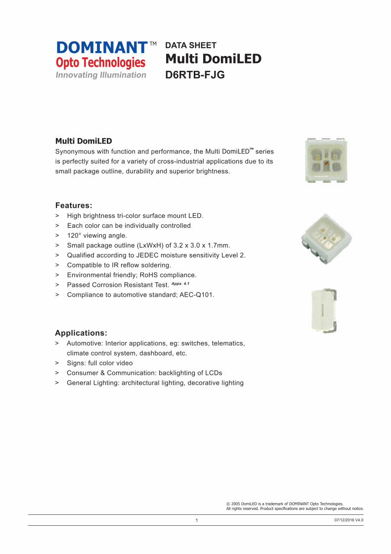
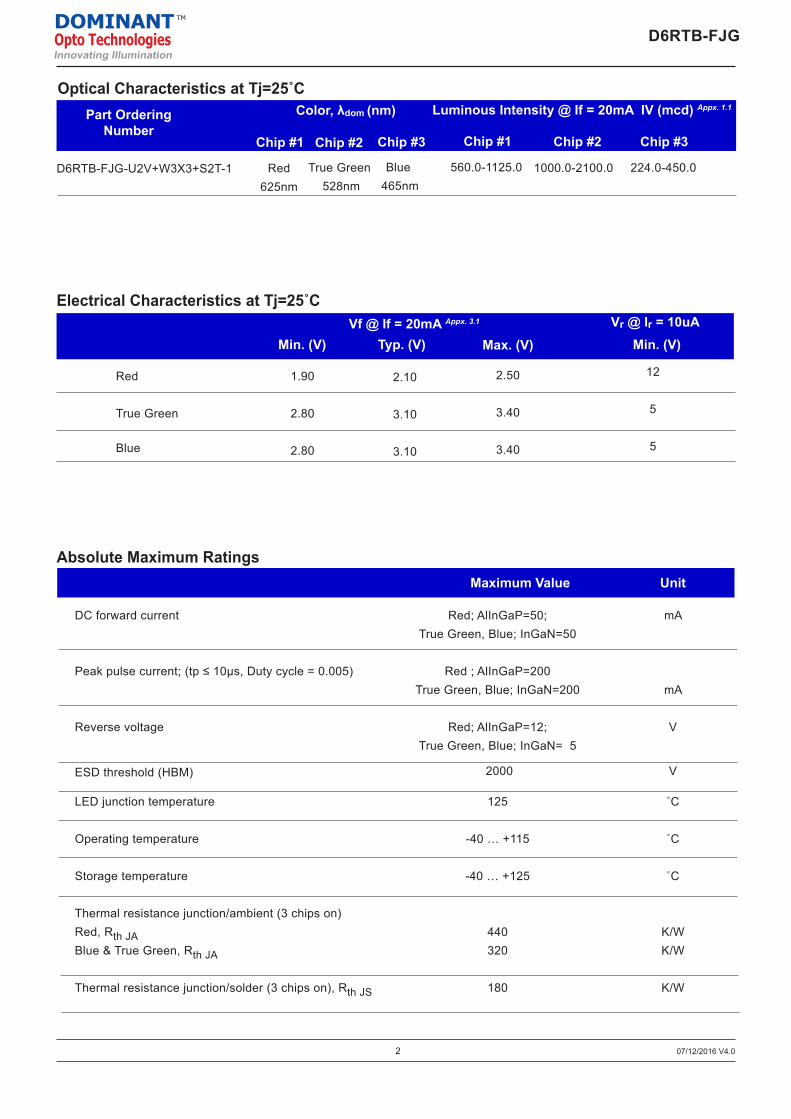
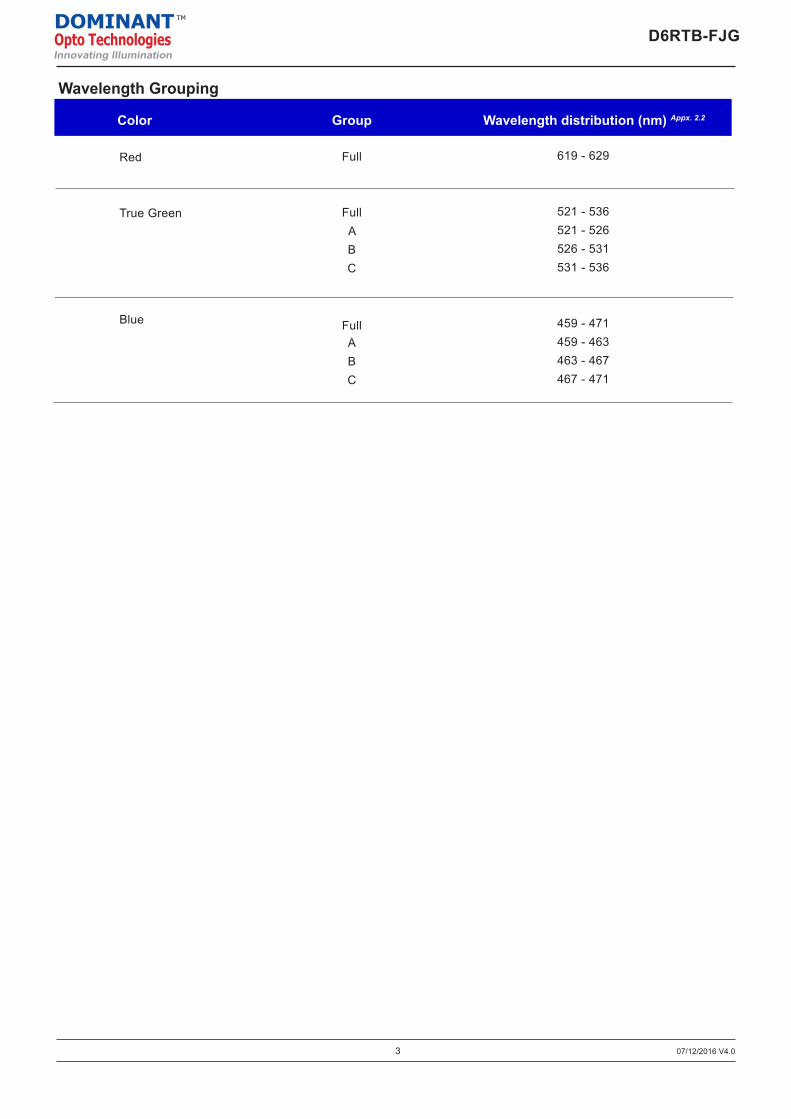
Features:> High brightness tri-color surface mount LED.> Each color can be individually controlled> 120° viewing angle.> Small package outline (LxWxH) of 3.2 x 3.0 x 1.7mm.> Qualified according to JEDEC moisture sensitivity Level 2.> Compatible to IR reflow soldering.> Environmental friendly; RoHS compliance.> Passed Corrosion Resistant Test. Appx. 4.1
> Compliance to automotive standard; AEC-Q101.
Multi DomiLEDSynonymous with function and performance, the Multi DomiLEDTM series is perfectly suited for a variety of cross-industrial applications due to its small package outline, durability and superior brightness.
DATA SHEET
Multi DomiLEDD6RTB-FJG
© 2005 DomiLED is a trademark of DOMINANT Opto Technologies.All rights reserved. Product specifications are subject to change without notice.
DOMINANTOpto TechnologiesInnovating Illumination
TM
07/12/2016 V4.0
Applications:> Automotive: Interior applications, eg: switches, telematics, climate control system, dashboard, etc.> Signs: full color video> Consumer & Communication: backlighting of LCDs> General Lighting: architectural lighting, decorative lighting
True Green 528nm
D6RTB-FJG-U2V+W3X3+S2T-1
2
Red 625nm
Part OrderingNumber
Color, λdom (nm)
Chip #1 Chip #2 Chip #3
Blue 465nm
Max. (V)Typ. (V)Vf @ If = 20mA Appx. 3.1
Electrical Characteristics at Tj=25˚C
Red
True Green
Blue
2.10
3.10
3.10
2.50
3.40
3.40
Min. (V)
1.90
2.80
2.80
Optical Characteristics at Tj=25˚CLuminous Intensity @ If = 20mA IV (mcd) Appx. 1.1
Chip #1 Chip #2 Chip #3
560.0-1125.0 1000.0-2100.0 224.0-450.0
07/12/2016 V4.0
Unit
Absolute Maximum RatingsMaximum Value
DC forward current
Peak pulse current; (tp ≤ 10µs, Duty cycle = 0.005)
Reverse voltage
ESD threshold (HBM)
LED junction temperature
Operating temperature
Storage temperature
Thermal resistance junction/ambient (3 chips on)Red, Rth JABlue & True Green, Rth JA
Thermal resistance junction/solder (3 chips on), Rth JS
Red; AlInGaP=50; True Green, Blue; InGaN=50
Red ; AlInGaP=200True Green, Blue; InGaN=200
Red; AlInGaP=12; True Green, Blue; InGaN= 5
2000
125
-40 … +115
-40 … +125
440320
180
mA
mA
V
V
˚C
˚C
˚C
K/WK/W
K/W
D6RTB-FJGDOMINANTOpto TechnologiesInnovating Illumination
TM
Vr @ Ir = 10uAMin. (V)
12
5
5
3 07/12/2016 V4.0
D6RTB-FJGDOMINANTOpto TechnologiesInnovating Illumination
TM
Group
Wavelength Grouping
Wavelength distribution (nm) Appx. 2.2Color
Red
True Green
Blue
Full
FullABC
FullABC
619 - 629
521 - 536521 - 526526 - 531531 - 536
459 - 471459 - 463463 - 467467 - 471
4
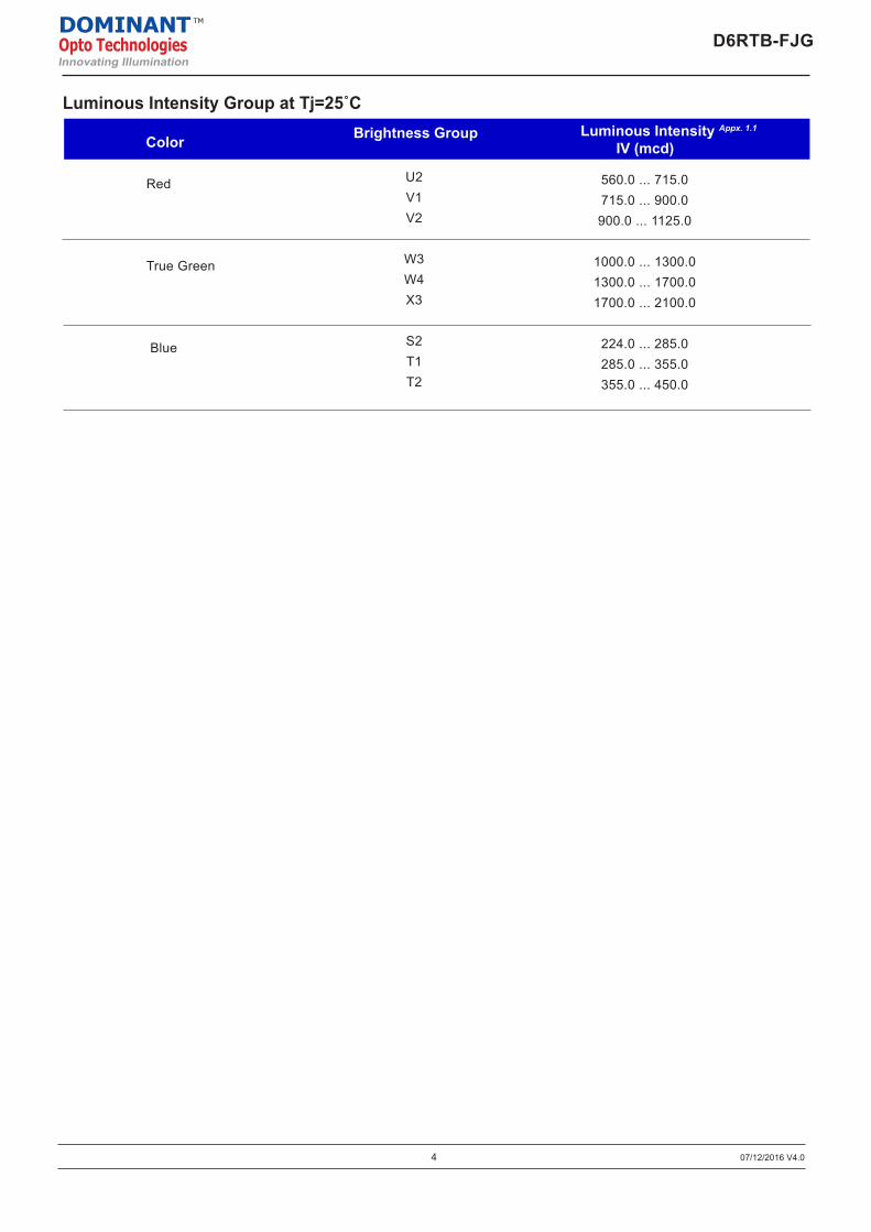
Color
Red
True Green
Blue
Luminous Intensity Appx. 1.1
IV (mcd)
Luminous Intensity Group at Tj=25˚CBrightness Group
U2V1V2
W3W4X3
S2T1T2
560.0 ... 715.0715.0 ... 900.0900.0 ... 1125.0
1000.0 ... 1300.01300.0 ... 1700.01700.0 ... 2100.0
224.0 ... 285.0285.0 ... 355.0355.0 ... 450.0
07/12/2016 V4.0
D6RTB-FJGDOMINANTOpto TechnologiesInnovating Illumination
TM
5 07/12/2016 V4.0
D6RTB-FJGDOMINANTOpto TechnologiesInnovating Illumination
TM
Luminous Intensity Group at Tj=25˚C
Forward Voltage VF (V)
Forward Current IF (mA)
Forw
ard
Cur
rent
I F (m
A)
Rel
ativ
e Lu
min
ous
Inte
nsity
I rel
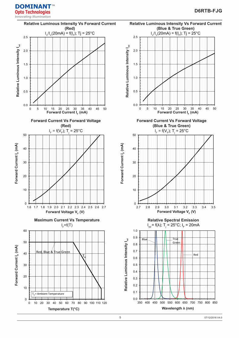
Relative Luminous Intensity Vs Forward Current(Red)
IV/IV(20mA) = f(IF); Tj = 25°C
Forw
ard
Cur
rent
I F (m
A)
Temperature T(°C)
Maximum Current Vs TemperatureIF=f(T)
Relative Spectral EmissionIrel = f(λ); Tj = 25°C; IF = 20mA
Rel
ativ
e Lu
min
ous
Inte
nsity
I rel
Wavelength λ (nm)
Forward Voltage VF (V)
Forward Current IF (mA)
Forw
ard
Cur
rent
I F (m
A)
Rel
ativ
e Lu
min
ous
Inte
nsity
I rel
0.0
0.5
1.0
1.5
2.0
2.5
0 5 10 15 20 25 30 35 40 45 50
0
10
20
30
40
50
2.7 2.8 2.9 3.0 3.1 3.2 3.3 3.4 3.5
Forw
ard
Cur
rent
I F
Forward Current IF (mA)
Forward Current Vs Forward Voltage (Blue & True Green)IF = f(VF); Tj = 25°C
Forward Voltage VF (V)
0.0
0.1
0.2
0.3
0.4
0.5
0.6
0.7
0.8
0.9
1.0
350 400 450 500 550 600 650 700 750 800 850
True Green
Blue
Wavelength λ (nm)
Forw
ard
Cur
rent
I F(m
A)
Maximum Current Vs Temperature (3 Chips on)IF = f (T)
Temperature T(°C)
Ta
0
10
20
30
40
50
60
0 10 20 30 40 50 60 70 80 90 100 110 120
Ta = Ambient Temperature
Relative Luminous Intensity Vs Forward Current (Red)IV/IV(20mA) = f(IF); Tj = 25°C
Rel
ativ
e Lu
min
ous
Inte
nsity
I rel
Rel
ativ
e Lu
min
ous
Inte
nsity
I rel
Relative Spectral EmissionIrel = f(λ); Tj = 25°C; IF = 20mA
0.0
0.5
1.0
1.5
2.0
2.5
0 5 10 15 20 25 30 35 40 45 50
Forward Current IF (mA)
Relative Luminous Intensity Vs Forward Current (Blue & True Green)IV/IV(20mA) = f(IF); Tj = 25°C
Rel
ativ
e Lu
min
ous
Inte
nsity
I rel
0
10
20
30
40
50
1.6 1.7 1.8 1.9 2.0 2.1 2.2 2.3 2.4 2.5 2.6 2.7
Forward Current Vs Forward Voltage (Red)IF = f(VF); Tj = 25°C
Forward Voltage VF (V)
RedRed, Blue & True Green
0.0
0.5
1.0
1.5
2.0
2.5
0 5 10 15 20 25 30 35 40 45 50
0
10
20
30
40
50
2.7 2.8 2.9 3.0 3.1 3.2 3.3 3.4 3.5
Forw
ard
Cur
rent
I FForward Current IF (mA)
Forward Current Vs Forward Voltage (Blue & True Green)IF = f(VF); Tj = 25°C
Forward Voltage VF (V)
0.0
0.1
0.2
0.3
0.4
0.5
0.6
0.7
0.8
0.9
1.0
350 400 450 500 550 600 650 700 750 800 850
True Green
Blue
Wavelength λ (nm)
Forw
ard
Cur
rent
I F(m
A)
Maximum Current Vs Temperature (3 Chips on)IF = f (T)
Temperature T(°C)
Ta
0
10
20
30
40
50
60
0 10 20 30 40 50 60 70 80 90 100 110 120
Ta = Ambient Temperature
Relative Luminous Intensity Vs Forward Current (Red)IV/IV(20mA) = f(IF); Tj = 25°C
Rel
ativ
e Lu
min
ous
Inte
nsity
I rel
Rel
ativ
e Lu
min
ous
Inte
nsity
I rel
Relative Spectral EmissionIrel = f(λ); Tj = 25°C; IF = 20mA
0.0
0.5
1.0
1.5
2.0
2.5
0 5 10 15 20 25 30 35 40 45 50
Forward Current IF (mA)
Relative Luminous Intensity Vs Forward Current (Blue & True Green)IV/IV(20mA) = f(IF); Tj = 25°C
Rel
ativ
e Lu
min
ous
Inte
nsity
I rel
0
10
20
30
40
50
1.6 1.7 1.8 1.9 2.0 2.1 2.2 2.3 2.4 2.5 2.6 2.7
Forward Current Vs Forward Voltage (Red)IF = f(VF); Tj = 25°C
Forward Voltage VF (V)
RedRed, Blue & True Green
0.0
0.5
1.0
1.5
2.0
2.5
0 5 10 15 20 25 30 35 40 45 50
0
10
20
30
40
50
2.7 2.8 2.9 3.0 3.1 3.2 3.3 3.4 3.5
Forw
ard
Cur
rent
I F
Forward Current IF (mA)
Forward Current Vs Forward Voltage (Blue & True Green)IF = f(VF); Tj = 25°C
Forward Voltage VF (V)
0.0
0.1
0.2
0.3
0.4
0.5
0.6
0.7
0.8
0.9
1.0
350 400 450 500 550 600 650 700 750 800 850
True Green
Blue
Wavelength λ (nm)
Forw
ard
Cur
rent
I F(m
A)
Maximum Current Vs Temperature (3 Chips on)IF = f (T)
Temperature T(°C)
Ta
0
10
20
30
40
50
60
0 10 20 30 40 50 60 70 80 90 100 110 120
Ta = Ambient Temperature
Relative Luminous Intensity Vs Forward Current (Red)IV/IV(20mA) = f(IF); Tj = 25°C
Rel
ativ
e Lu
min
ous
Inte
nsity
I rel
Rel
ativ
e Lu
min
ous
Inte
nsity
I rel
Relative Spectral EmissionIrel = f(λ); Tj = 25°C; IF = 20mA
0.0
0.5
1.0
1.5
2.0
2.5
0 5 10 15 20 25 30 35 40 45 50
Forward Current IF (mA)
Relative Luminous Intensity Vs Forward Current (Blue & True Green)IV/IV(20mA) = f(IF); Tj = 25°C
Rel
ativ
e Lu
min
ous
Inte
nsity
I rel
0
10
20
30
40
50
1.6 1.7 1.8 1.9 2.0 2.1 2.2 2.3 2.4 2.5 2.6 2.7
Forward Current Vs Forward Voltage (Red)IF = f(VF); Tj = 25°C
Forward Voltage VF (V)
RedRed, Blue & True Green
Relative Luminous Intensity Vs Forward Current(Blue & True Green)
IV/IV(20mA) = f(IF); Tj = 25°C
0.0
0.5
1.0
1.5
2.0
2.5
0 5 10 15 20 25 30 35 40 45 50
0
10
20
30
40
50
2.7 2.8 2.9 3.0 3.1 3.2 3.3 3.4 3.5
Forw
ard
Cur
rent
I FForward Current IF (mA)
Forward Current Vs Forward Voltage (Blue & True Green)IF = f(VF); Tj = 25°C
Forward Voltage VF (V)
0.0
0.1
0.2
0.3
0.4
0.5
0.6
0.7
0.8
0.9
1.0
350 400 450 500 550 600 650 700 750 800 850
True Green
Blue
Wavelength λ (nm)
Forw
ard
Cur
rent
I F(m
A)
Maximum Current Vs Temperature (3 Chips on)IF = f (T)
Temperature T(°C)
Ta
0
10
20
30
40
50
60
0 10 20 30 40 50 60 70 80 90 100 110 120
Ta = Ambient Temperature
Relative Luminous Intensity Vs Forward Current (Red)IV/IV(20mA) = f(IF); Tj = 25°C
Rel
ativ
e Lu
min
ous
Inte
nsity
I rel
Rel
ativ
e Lu
min
ous
Inte
nsity
I rel
Relative Spectral EmissionIrel = f(λ); Tj = 25°C; IF = 20mA
0.0
0.5
1.0
1.5
2.0
2.5
0 5 10 15 20 25 30 35 40 45 50
Forward Current IF (mA)
Relative Luminous Intensity Vs Forward Current (Blue & True Green)IV/IV(20mA) = f(IF); Tj = 25°C
Rel
ativ
e Lu
min
ous
Inte
nsity
I rel
0
10
20
30
40
50
1.6 1.7 1.8 1.9 2.0 2.1 2.2 2.3 2.4 2.5 2.6 2.7
Forward Current Vs Forward Voltage (Red)IF = f(VF); Tj = 25°C
Forward Voltage VF (V)
RedRed, Blue & True Green
Forward Current Vs Forward Voltage(Red)
IF = f(VF); Tj = 25°C
0.0
0.5
1.0
1.5
2.0
2.5
0 5 10 15 20 25 30 35 40 45 50
0
10
20
30
40
50
2.7 2.8 2.9 3.0 3.1 3.2 3.3 3.4 3.5
Forw
ard
Cur
rent
I F
Forward Current IF (mA)
Forward Current Vs Forward Voltage (Blue & True Green)IF = f(VF); Tj = 25°C
Forward Voltage VF (V)
0.0
0.1
0.2
0.3
0.4
0.5
0.6
0.7
0.8
0.9
1.0
350 400 450 500 550 600 650 700 750 800 850
True Green
Blue
Wavelength λ (nm)
Forw
ard
Cur
rent
I F(m
A)
Maximum Current Vs Temperature (3 Chips on)IF = f (T)
Temperature T(°C)
Ta
0
10
20
30
40
50
60
0 10 20 30 40 50 60 70 80 90 100 110 120
Ta = Ambient Temperature
Relative Luminous Intensity Vs Forward Current (Red)IV/IV(20mA) = f(IF); Tj = 25°C
Rel
ativ
e Lu
min
ous
Inte
nsity
I rel
Rel
ativ
e Lu
min
ous
Inte
nsity
I rel
Relative Spectral EmissionIrel = f(λ); Tj = 25°C; IF = 20mA
0.0
0.5
1.0
1.5
2.0
2.5
0 5 10 15 20 25 30 35 40 45 50
Forward Current IF (mA)
Relative Luminous Intensity Vs Forward Current (Blue & True Green)IV/IV(20mA) = f(IF); Tj = 25°C
Rel
ativ
e Lu
min
ous
Inte
nsity
I rel
0
10
20
30
40
50
1.6 1.7 1.8 1.9 2.0 2.1 2.2 2.3 2.4 2.5 2.6 2.7
Forward Current Vs Forward Voltage (Red)IF = f(VF); Tj = 25°C
Forward Voltage VF (V)
RedRed, Blue & True Green
Forward Current Vs Forward Voltage(Blue & True Green)IF = f(VF); Tj = 25°C
0.0
0.5
1.0
1.5
2.0
2.5
0 5 10 15 20 25 30 35 40 45 50
0
10
20
30
40
50
2.7 2.8 2.9 3.0 3.1 3.2 3.3 3.4 3.5
Forw
ard
Cur
rent
I FForward Current IF (mA)
Forward Current Vs Forward Voltage (Blue & True Green)IF = f(VF); Tj = 25°C
Forward Voltage VF (V)
0.0
0.1
0.2
0.3
0.4
0.5
0.6
0.7
0.8
0.9
1.0
350 400 450 500 550 600 650 700 750 800 850
True Green
Blue
Wavelength λ (nm)
Forw
ard
Cur
rent
I F(m
A)
Maximum Current Vs Temperature (3 Chips on)IF = f (T)
Temperature T(°C)
Ta
0
10
20
30
40
50
60
0 10 20 30 40 50 60 70 80 90 100 110 120
Ta = Ambient Temperature
Relative Luminous Intensity Vs Forward Current (Red)IV/IV(20mA) = f(IF); Tj = 25°C
Rel
ativ
e Lu
min
ous
Inte
nsity
I rel
Rel
ativ
e Lu
min
ous
Inte
nsity
I rel
Relative Spectral EmissionIrel = f(λ); Tj = 25°C; IF = 20mA
0.0
0.5
1.0
1.5
2.0
2.5
0 5 10 15 20 25 30 35 40 45 50
Forward Current IF (mA)
Relative Luminous Intensity Vs Forward Current (Blue & True Green)IV/IV(20mA) = f(IF); Tj = 25°C
Rel
ativ
e Lu
min
ous
Inte
nsity
I rel
0
10
20
30
40
50
1.6 1.7 1.8 1.9 2.0 2.1 2.2 2.3 2.4 2.5 2.6 2.7
Forward Current Vs Forward Voltage (Red)IF = f(VF); Tj = 25°C
Forward Voltage VF (V)
RedRed, Blue & True Green
6 07/12/2016 V4.0
D6RTB-FJGDOMINANTOpto TechnologiesInnovating Illumination
TM
Allo
wab
le F
orw
ard
Cur
rent
I F( m
A )
Duty Ratio, %
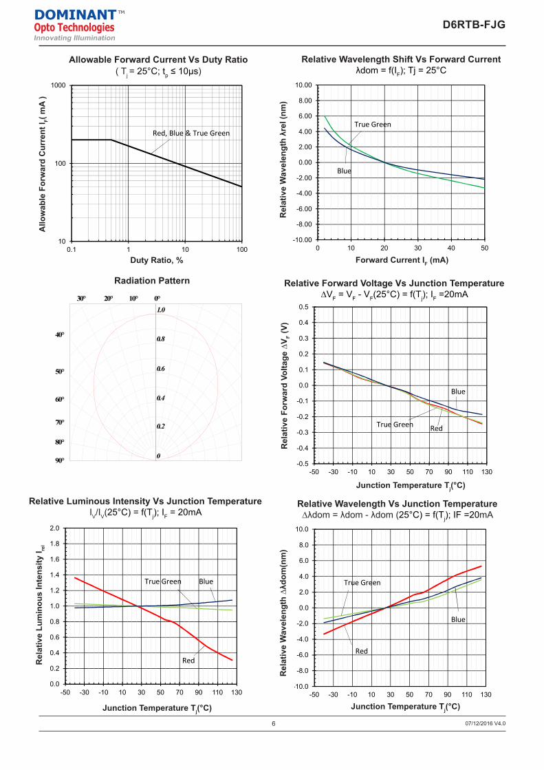
Allowable Forward Current Vs Duty Ratio ( Tj = 25°C; tp ≤ 10μs)
Radiation Pattern
Forward Current IF (mA)
Relative Wavelength Shift Vs Forward Currentλdom = f(IF); Tj = 25°C
Rel
ativ
e W
avel
engt
h λr
el (n
m)
Allo
wab
le F
orw
ard
Cur
rent
I F( m
A )
Allowable Forward Current Vs Duty Ratio ( Tj = 25°C; tp ≤ 10μs )
Duty Ratio, %
10
100
1000
0.1 1 10 100
-0.5
-0.4
-0.3
-0.2
-0.1
0.0
0.1
0.2
0.3
0.4
0.5
-50 -30 -10 10 30 50 70 90 110 130
Blue
0.0
0.2
0.4
0.6
0.8
1.0
1.2
1.4
1.6
1.8
2.0
-50 -30 -10 10 30 50 70 90 110 130
Rel
ativ
e Fo
rwar
d Vo
ltage
∆V F
(V)
Relative Forward Voltage Vs Junction Temperature∆VF = VF - VF(25°C) = f(Tj); IF = 20mA
Junction Temperature Tj(°C) Junction Temperature Tj(°C)
Relative Luminous Intensity Vs Junction TemperatureIV /IV (25°C) = f(Tj); IV = 20mA
Rel
ativ
e Lu
min
ous
Inte
nsity
I rel
RedTrue Green
True Green
Red
Red, Blue & True Green
Blue
-0.020
-0.015
-0.010
-0.005
0.000
0.005
0.010
0.015
0.020
0 5 10 15 20 25 30 35 40 45 50-10.00
-8.00
-6.00
-4.00
-2.00
0.00
2.00
4.00
6.00
8.00
10.00
0 10 20 30 40 50
Rel
ativ
e W
avel
engt
h λ r
el
Relative Wavelength Shift Vs Forward Current
Forward Current IF (mA)
∆Cx,
∆C
y
Chromaticity Coordinate Shift Vs Forward Current∆Cx, ∆Cy = f(IF);Tj = 25°C
Forward Current IF (mA)
Blue
True Green
0.270°
90°
80°
0
60°
50°
40°
30° 20°
0.6
0.4
1.0
0.8
10° 0°
Junction Temperature Tj(°C)
Rel
ativ
e Fo
rwar
d Vo
ltage
∆V F (
V)Relative Forward Voltage Vs Junction Temperature
∆VF = VF - VF(25°C) = f(Tj); IF =20mA
Junction Temperature Tj(°C)
Rel
ativ
e W
avel
engt
h ∆λ
dom
(nm
)
Relative Wavelength Vs Junction Temperature∆λdom = λdom - λdom (25°C) = f(Tj); IF =20mA
Allo
wab
le F
orw
ard
Cur
rent
I F( m
A )
Allowable Forward Current Vs Duty Ratio ( Tj = 25°C; tp ≤ 10μs )
Duty Ratio, %
10
100
1000
0.1 1 10 100
-0.5
-0.4
-0.3
-0.2
-0.1
0.0
0.1
0.2
0.3
0.4
0.5
-50 -30 -10 10 30 50 70 90 110 130
Blue
0.0
0.2
0.4
0.6
0.8
1.0
1.2
1.4
1.6
1.8
2.0
-50 -30 -10 10 30 50 70 90 110 130
Rel
ativ
e Fo
rwar
d Vo
ltage
∆V F
(V)
Relative Forward Voltage Vs Junction Temperature∆VF = VF - VF(25°C) = f(Tj); IF = 20mA
Junction Temperature Tj(°C) Junction Temperature Tj(°C)
Relative Luminous Intensity Vs Junction TemperatureIV /IV (25°C) = f(Tj); IV = 20mA
Rel
ativ
e Lu
min
ous
Inte
nsity
I rel
RedTrue Green
True Green
Red
Red, Blue & True Green
Blue
Junction Temperature Tj(°C)
Rel
ativ
e Lu
min
ous
Inte
nsity
I rel
Relative Luminous Intensity Vs Junction TemperatureIV/IV(25°C) = f(Tj); IF = 20mA
-10.0
-8.0
-6.0
-4.0
-2.0
0.0
2.0
4.0
6.0
8.0
10.0
-50 -30 -10 10 30 50 70 90 110 130
∆Cx
∆Cy
-0.030
-0.025
-0.020
-0.015
-0.010
-0.005
0.000
0.005
0.010
0.015
0.020
0.025
0.030
-50 -30 -10 10 30 50 70 90 110 130
Rel
ativ
e W
avel
engt
h ∆λ
dom
(nm
)
Relative Wavelength Vs Junction Temperature∆λdom = λdom - λdom (25°C) = f(Tj); IF = 20mA
∆Cx,
∆C
yChromaticity Coordinate Shift Vs Junction Temperature
∆Cx, ∆Cy = f(Tj); IF = 20mA
Junction Temperature Tj(°C) Junction Temperature Tj(°C)
True Green
Red
Blue
7
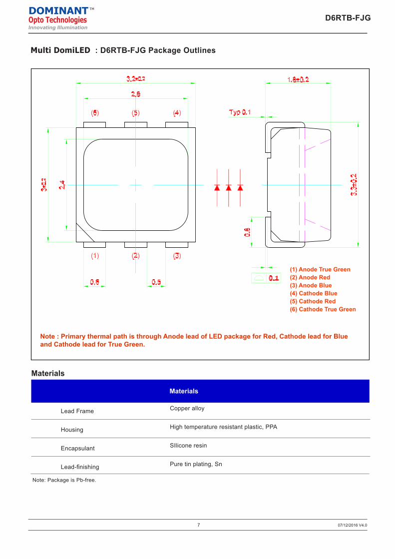
Multi DomiLED : D6RTB-FJG Package Outlines
Note: Package is Pb-free.
Materials
Lead Frame
Housing
Encapsulant
Lead-finishing
Materials
Copper alloy
High temperature resistant plastic, PPA
SIlicone resin
Pure tin plating, Sn
07/12/2016 V4.0
D6RTB-FJGDOMINANTOpto TechnologiesInnovating Illumination
TM
Note : Primary thermal path is through Anode lead of LED package for Red, Cathode lead for Blue and Cathode lead for True Green.
(1) Anode True Green(2) Anode Red(3) Anode Blue(4) Cathode Blue(5) Cathode Red(6) Cathode True Green
8
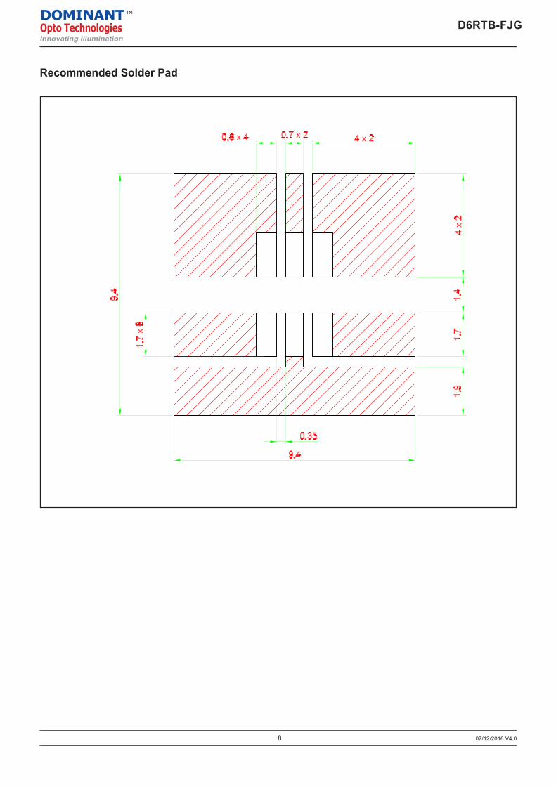
Recommended Solder Pad
07/12/2016 V4.0
D6RTB-FJGDOMINANTOpto TechnologiesInnovating Illumination
TM
9
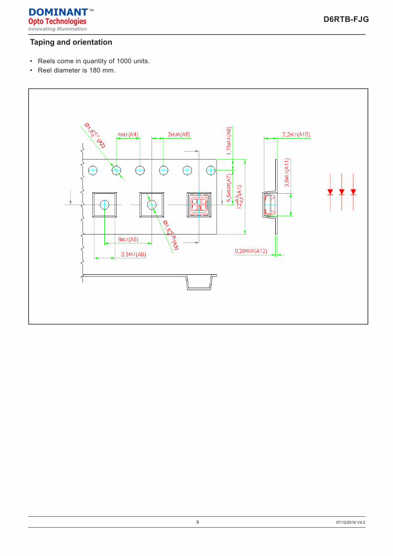
Taping and orientation
• Reels come in quantity of 1000 units.• Reel diameter is 180 mm.
07/12/2016 V4.0
D6RTB-FJGDOMINANTOpto TechnologiesInnovating Illumination
TM
DOMINANT Opto Technologies DRND-008
Issue No : 1 Page 1 of 2
Product & Process Change Notice (PCN)
PCN No: D150070 Date: 1-Aug -2015
1. Describe present process / product:
All PLCC6 packages; D6RTB.
2. Product type affected:
All PLCC6 packages; D6RTB.
3. Describe changes (to be):
Current carrier tape design for all PLCC6 (D6RTB) packages is as illustrated below.
This PCN seek for approval to change the design to the new proposal below.
10
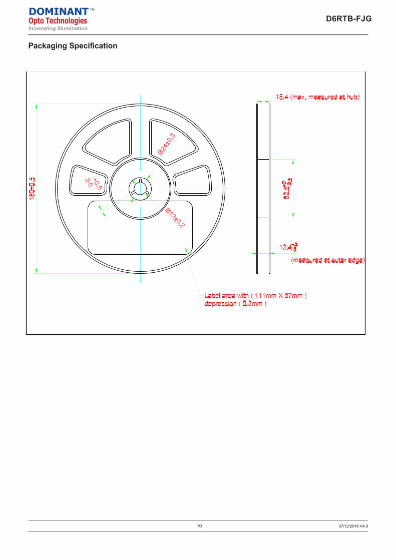
Packaging Specification
07/12/2016 V4.028/10/2010 V8.010
Packaging Specification
AllnGaP : DDx-xRSDOMINANTOpto TechnologiesInnovating Illumination
TM D6RTB-FJGDOMINANTOpto TechnologiesInnovating Illumination
TM
11 07/12/2016 V4.0
D6RTB-FJGDOMINANTOpto TechnologiesInnovating Illumination
TM
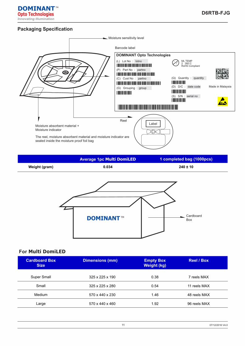
Packaging Specification
Average 1pc Multi DomiLED 1 completed bag (1000pcs)
0.034 190 ± 10Weight (gram)
CardboardBox
Dimensions (mm) Empty BoxWeight (kg)
Super Small
Small
Medium
Large
For Multi DomiLED
Reel / BoxCardboard BoxSize
Weight (gram) 0.034 240 ± 10
DOMINANT TM
Moisture sensitivity level
Moisture absorbent material +Moisture indicator
The reel, moisture absorbent material and moisture indicator aresealed inside the moisture proof foil bag
Reel
Barcode label
Label
(L) Lot No : lotno
(P) Part No : partno
(C) Cust No : partno
(G) Grouping : group
(Q) Quantity : quantity
(D) D/C : date code
(S) S/N : serial no
DOMINANT Opto TechnologiesML TEMP2 260˚CRoHS Compliant
Made in Malaysia
DOMINANT Opto Technologies DRND-008
Issue No : 1 Page 1 of 3
Product & Process Change Notice (PCN)
PCN No: D140157 Date: 21-Nov -2014
1. Describe present process / product:
All SMD LEDs that are currently shipped in the reel form. Please refer to section 3 for
the details; comparing current packing and label specification versus change proposed.
2. Product type affected:
All SMD LEDs that are currently shipped in the reel form.
3. Describe changes (to be):
Existing barcode printed label (BPL) used is as shown below.
Existing BPL size - 87mm x 45mm. As part of improvement and also in response to customers’ request; BPL format will be
changed to the following.
New BPL size - 110mm x 55mm. Additional information are now included in the label. 2D and 3D barcode data are
implemented now for every data field.
325 x 225 x 190
325 x 225 x 280
570 x 440 x 230
570 x 440 x 460
0.38
0.54
1.46
1.92
7 reels MAX
11 reels MAX
48 reels MAX
96 reels MAX
12
Time (sec)0 50 100 150 200
300
250
225
200
175
150
125
100
75
50
25
275
Tem
pera
ture
(˚C
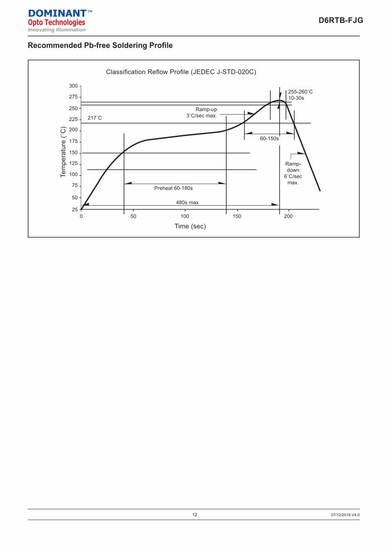
)Classification Reflow Profile (JEDEC J-STD-020C)
Ramp-up3˚C/sec max.
255-260˚C10-30s
60-150s
Ramp-down
6˚C/secmax.
Preheat 60-180s
480s max
217˚C
Recommended Pb-free Soldering Profile
07/12/2016 V4.0
D6RTB-FJGDOMINANTOpto TechnologiesInnovating Illumination
TM
13 07/12/2016 V4.0
D6RTB-FJGDOMINANTOpto TechnologiesInnovating Illumination
TM
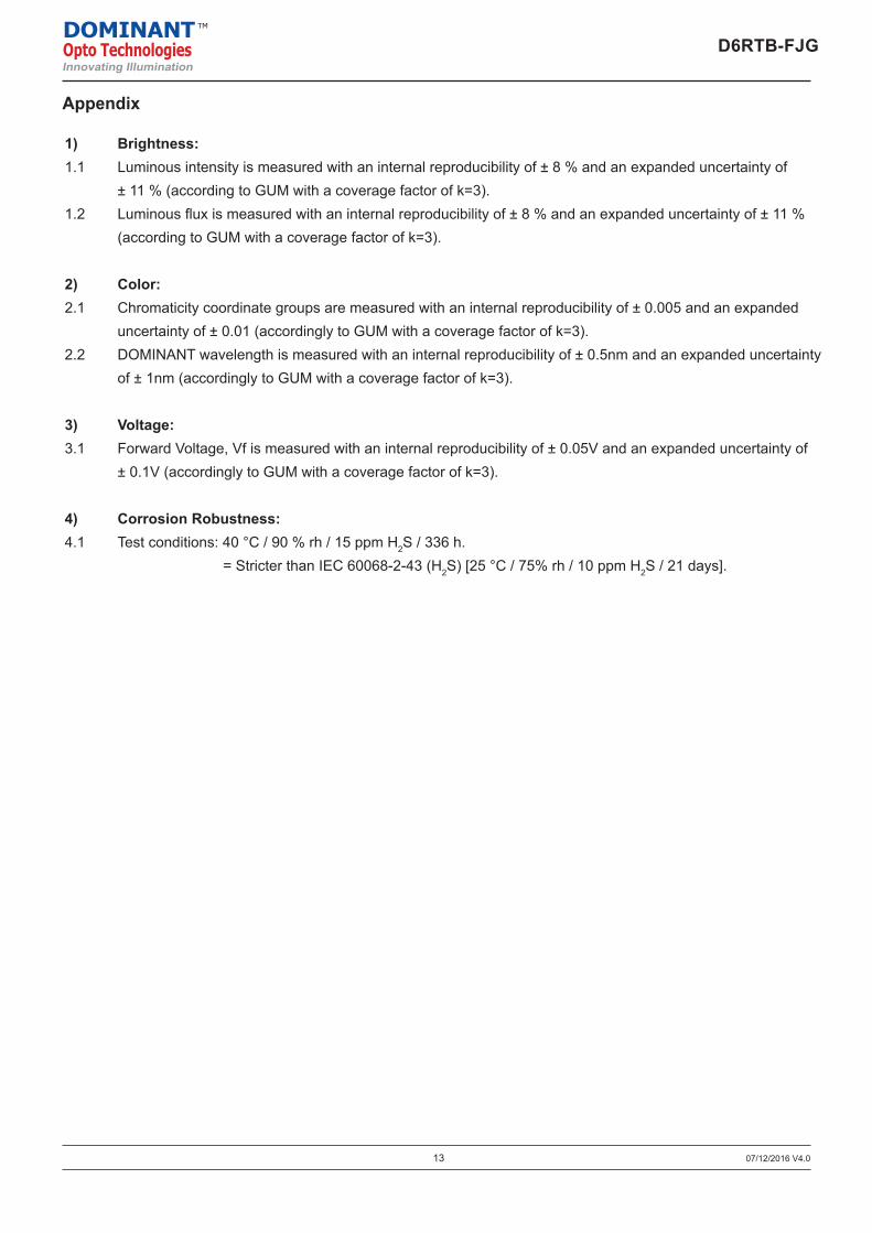
Appendix
1) Brightness:1.1 Luminous intensity is measured with an internal reproducibility of ± 8 % and an expanded uncertainty of ± 11 % (according to GUM with a coverage factor of k=3).1.2 Luminous flux is measured with an internal reproducibility of ± 8 % and an expanded uncertainty of ± 11 % (according to GUM with a coverage factor of k=3).
2) Color:2.1 Chromaticity coordinate groups are measured with an internal reproducibility of ± 0.005 and an expanded uncertainty of ± 0.01 (accordingly to GUM with a coverage factor of k=3).2.2 DOMINANT wavelength is measured with an internal reproducibility of ± 0.5nm and an expanded uncertainty of ± 1nm (accordingly to GUM with a coverage factor of k=3).
3) Voltage:3.1 Forward Voltage, Vf is measured with an internal reproducibility of ± 0.05V and an expanded uncertainty of ± 0.1V (accordingly to GUM with a coverage factor of k=3).
4) Corrosion Robustness:4.1 Test conditions: 40 °C / 90 % rh / 15 ppm H2S / 336 h. = Stricter than IEC 60068-2-43 (H2S) [25 °C / 75% rh / 10 ppm H2S / 21 days].
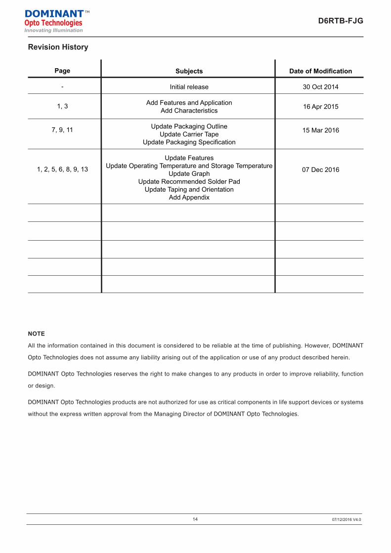
Revision History
NOTE
All the information contained in this document is considered to be reliable at the time of publishing. However, DOMINANT
Opto Technologies does not assume any liability arising out of the application or use of any product described herein.
DOMINANT Opto Technologies reserves the right to make changes to any products in order to improve reliability, function
or design.
DOMINANT Opto Technologies products are not authorized for use as critical components in life support devices or systems
without the express written approval from the Managing Director of DOMINANT Opto Technologies.
Page
-
1, 3
7, 9, 11
1, 2, 5, 6, 8, 9, 13
Subjects
Initial release
Add Features and ApplicationAdd Characteristics
Update Packaging OutlineUpdate Carrier Tape
Update Packaging Specification
Update FeaturesUpdate Operating Temperature and Storage Temperature
Update GraphUpdate Recommended Solder Pad
Update Taping and OrientationAdd Appendix
Date of Modification
30 Oct 2014
16 Apr 2015
15 Mar 2016
07 Dec 2016
14 07/12/2016 V4.0
D6RTB-FJGDOMINANTOpto TechnologiesInnovating Illumination
TM
About Us
DOMINANT Opto Technologies is a dynamic company that is amongst the world’s leading automotive LED manu-facturers. With an extensive industry experience and relentless pursuit of innovation, DOMINANT’s state-of-art manufacturing and development capabilities have become a trusted and reliable brand across the globe. More in-formation about DOMINANT Opto Technologies, a ISO/TS 16949 and ISO 14001 certified company, can be found under http://www.dominant-semi.com.
Please contact us for more information:
DOMINANT Opto Technologies Sdn. Bhd.Lot 6, Batu Berendam, FTZ Phase III, 75350 Melaka, MalaysiaTel: (606) 283 3566 Fax: (606) 283 0566E-mail: [email protected]
D6RTB-FJGDOMINANTOpto TechnologiesInnovating Illumination
TM