Embed Size (px)
Citation preview

OG_MU-D1-R_v10e
OPERATION GUIDE
Embedded low power radio modem
MU-D1-R 915MHz
Operation Guide
Version 1.0 (Dec. 2010)
CIRCUIT DESIGN, INC.
7557-1 Hotaka, Azumino
Nagano 399-8303, JAPAN
Tel: +81-(0)263-82-1024
Fax: +81-(0)263-82-1016
E-mail: [email protected] Web site: http://www.circuitdesign.jp

OG_MU-D1-R_v10e Circuit Design, Inc.
2
OPERATION GUIDE
Chapter 1 The MU-D1-R 4
1.1 Outline 4 1.1.1 Features 4 1.1.2 Applications 4
1.2 Block Diagram 5 1.3 Example of the Control Method 6
1.3.1 Example 1: Controlling the MU-D1-R with the on-board CPU 6 1.3.2 Example 2: Controlling the MU-D1-R via RS232C 6
Chapter 2 Specifications and Diagram 7
2.1 Main Specifications 7 2.1.1 General specifications 7 2.1.2 UART interface specifications 7
2.2 Terminal Specifications 8 2.3 Channel Table 10 2.4 Dimensional Drawing 11
2.4.1 External dimensions 11 2.4.2 Diagram of dimensions for hole positions 11
Chapter 3 How to Design a User System 12
3.1 Circuit Board Design 12 3.3 The Antenna 13 3.4 Miscellaneous 13
Chapter 4 How to Use the MU-D1-R 14 4.1 Communication Concept 14
4.1.1 Station types and link parameters 14 4.1.2 Basic data transmission 15 4.1.3 The link parameters 15 4.1.4 Conditions for establishing a link 16
4.2 System Configuration 17 4.2.1 Communication within a group 17
4.3 Modes 18 4.3.1 Command mode 18 4.3.2 Text mode 18 4.3.3 Binary mode 18 4.3.4 Mode setting 19
4.4 Resetting 20 4.5 Initializing 20 4.6 Power amplifier On/Off setting 20
Chapter 5 Commands, Responses and Receives 21
5.1 About the Commands, Responses and Receives 21 5.2 Command, Response and Receive Table 23
5.2.1 Data transmit command and data transmit response 23 5.2.2 Data receives 23 5.2.3 Control commands and control responses 23 5.2.4 Monitor commands and monitor responses 24 5.2.5 Test commands and test responses 24 5.2.6 Receive response 24 5.2.7 Error response 24
5.3 Save Setting Command Options 24 5.4 Command, Response and Receive Details 26
5.4.1 Data transmit command, response and data receive 26 5.4.1.1 @DT Data transmit command 1 27
Contents

OG_MU-D1-R_v10e Circuit Design, Inc.
3
OPERATION GUIDE
5.4.2 Control commands and control responses 28 5.4.2.1 @BR UART baud rate setting 28 5.4.2.2 @CH Frequency channel setting 28 5.4.2.3 @DI Destination ID setting 29 5.4.2.4 @EI Equipment ID setting 29 5.4.2.5 @GI Group ID setting 29 5.4.2.6 @IZ Initialize 29 5.4.2.7 @MD Operation mode register setting 29 5.4.2.8 @PB UART parity bit setting 30 5.4.2.9 @PA Power amplifier On/Off setting 30 5.4.2.10 @PW Antenna power setting 30 5.4.2.11 @RM Response display mode 30 5.4.2.12 @SB UART stop bit setting 30 5.4.2.13 @SR Show serial number 31 5.4.2.14 @SR Reset 31 5.4.2.15 @TB Time without input in the binary mode setting 31 5.4.2.16 @TC Command mode input waiting time 31 5.4.2.17 @UI User ID setting 31 5.4.2.18 @VR Display program version 32
5.4.3 Monitor commands and responses 32 5.4.3.1 @RA RSSI absolute value measurement 32 5.4.3.2 @RC All channel RSSI absolute level measurement 32
5.4.4 Test commands and test responses 33 5.4.4.1 @CT Test data transmission 33 5.4.4.2 @CP Packet test 33
5.4.5 Receive response 34 5.4.6 Error response 34
Chapter 6 How to Develop a Program 36
6.1 Outline of User Processes 36 6.2 The Operations of the MU-D1-R 37 6.3 Command Transmission 38
6.3.1 Issuing commands 38 6.3.2 Issuing data transmission command 38 6.3.3 Issuing commands continuously 39 6.3.4 Issuing commands continuously (when ignoring the response) 39
6.4 Response Processing 40 6.4.1 Responses and receives 40 6.4.2 Response and receive formats 40 6.4.3 Response and receive types 40 6.4.4 Response and receive processing 41
6.5 Assessing the Field Status for Communication 43 6.5.1 Source station RSSI measurement 43 6.5.2 Packet test 43
6.6 Achieving Data Transmission 44 6.7 Operation in Binary Mode 45
6.7.1 Modes 45 6.7.2 When developing a new system 46 6.7.3 When using only the data line of existing equipment 47 6.7.4 Conditions for use of the binary mode 47
Chapter 7 Timing 48 Chapter 8 Evaluation using HyperTerminal 51 Chapter 9 Regulatory Compliance 52

OG_MU-D1-R_v10e Circuit Design, Inc.
4
OPERATION GUIDE
The MU-D1-R is an FCC part15 compliant embedded low power radio modem for transmission of serial data. Since it is possible to control the radio component using dedicated simple commands, the user can concentrate on developing the transmitting and receiving programs for their system. The commands of MU-D1-R are compatible with the commands used for Circuit Design’s MU-1 and MU-2 series. Transmitting and receiving data and issuing commands are performed using a UART*
1 interface with a single-chip
CPU and the modem can also be controlled via the COM port (RS232C format) of the computer, making it possible for the user to develop systems quickly*
2.
The receiving part contains two independent receivers and operates as a true diversity receiver which provides stable receiving performance even in proximity operation prone to multipath effect. The MU-D1-R is designed to minimize design difficulties involving high frequency components, so that the user can embed the modem in their system with peace of mind.
Important
It is not possible simply to replace communication using existing RS232C system equipment connected with a cable, with MU-D1-R wireless communication. In order to build wireless systems, issues specific to radio communications must be solved. The hardware and software must be newly designed specifically for the MU-D1-R. *1 UART (Universal Asynchronous Receiver Transmitter)
*2 The RS232C interface board with a D-Sub 9-pin connector is available
1.1.1 Features
FCC part15.247 compliant Command compatible with the MU-1 and MU-2 series Serial data can be transmitted with a simple system of commands. Offers a wide communication range with stable operation. The true diversity receiving system achieves stable communication The transceiver function is incorporated within a compact unit. Ideal for battery operated applications thanks to operation at low voltage and low consumption current. Uses the UART interface commonly available with on-board CPUs. The high frequency circuit is designed specifically as an embedded radio unit, to operate stably on the user
system circuit board. 1:1, 1:N, and N:N systems can be built by flexibly setting link parameters. It is possible to assess locally the status of radio waves and field noise at the source station. RF power selectable by switching the power amplifier ON/OFF (40 mW / 8 mW) Using a TCXO in the control part achieves a wide operating temperature range from -20 ºC to 65 ºC
1.1.2 Applications Serial data transmission
Energy monitoring, data monitoring devices, handy terminals, barcode readers, housing equipment control Telecontrol
Various warning systems, remote control for construction machinery, display devices, motor control, lifters Remote control of FA equipment
Telemetry Security systems, water level monitors for rivers and dams, temperature and humidity gauges, rain gauges, pressure gauges, voltmeters, ampere meters
Chapter 1 The MU-D1-R
1.1 Outline

OG_MU-D1-R_v10e Circuit Design, Inc. 5
OPERATION GUIDE
ControlCPU
BPFSAW Filter
EEPROM
14
13
9
10
11
12
8
7
6
5
4
3
2
1
MU-D1-R 915MHz Block Diagram
DAT (NC)
TXL (TX-LED)
RXA (RX-LED)
TE1 (NC)
RST (RESET)
INI
MOD (MODE)
CTS
RTS
RXD
TXD
VCC
GND
RF
Chip select
Port
RXD
TXD
RESET
Port
Port
Port
Ports
RXD
Port
Note SAW: Surface Acoustic Wave
λ/4Antenna
Port
Port
DVCC for Digital parts
Regulator 3.8v for Power AMP
RF IC
IRQ-TXENCLKANT_NANT_P MISO
TCXO
Clock
RF
λ/4Antenna
RF SW RF SW
RF PowerAMP
RF IC
ANT_NANT_PCLK16MHz
Regulator 2.5v for RFIC
MISO
IRQ-TXENSYSCLKMOSI
MOSISELECTSELECT Port
Port
16MHz Ports
RXB (RX-LED)
PortPort1.2 Block Diagram

OG_MU-D1-R_v10e Circuit Design, Inc. 6
OPERATION GUIDE
The VCC terminal of the MU-D1-R is connected directly to the power source of the mounted CPU. Ensure that the voltage of the power supply is regulated to within DC +4.0 v to +5.0 v. Basically the MU-D1-R uses hardware flow control with RTS or CTS, however 3-line control can be used without the hardware flow control. In this case, set the CTS terminal to Low level. In addition, care is required with the timing of transmitting and receiving. Example 1 and Example 2 are basically the same methods except for the difference in control voltage.
1.3.1 Example 1: Controlling the MU-D1-R with the on-board CPU It is possible to interface the MU-D1-R directly using the UART interface of the on-board CPU.
RXDTXDCTS(Port)RTS(Port)Port User CPUWith UARTPeripheralDC +4.0v to +5.0vRegulator+- +4.0v to +5.0vDC PowerTx, RX-A, RX-B Indicator
AntennaAMU-D1-R
TXD 1RXD 2RTS 3CTS 4MOD 5INI 6RST 7NC 89 NC10 RXB11 TXL12 RXA13 VCC14 GNDAAAABBBB
AntennaB
1.3.2 Example 2: Controlling the MU-D1-R via RS232C 1. Using the RS232 port of your computer, you can develop a new program for OS’s such as Windows and the like.
In this case, use an RS232C transceiver. (The program for existing system equipment will not work.) 2. By supplying power to the MU-D1-R with a cable, you can also isolate the radio component from your system and
locate it in the most suitable environment. The distance can be extended by 15 m to 50 m, but the exact distance should be confirmed through experiments.
* It is also possible to supply power using the No.1 pin of the D-Sub-connector.
1.3 Example of the Control Method

OG_MU-D1-R_v10e Circuit Design, Inc. 7
OPERATION GUIDE
2.1.1 General specifications
Temperature conditions: +25ºC ± 5ºC, typical
Item Specification (Typ.) Remarks
Compatible standards FCC part15.247
Emission class G1D
Antenna power (selectable) 40 mW (PA ON) 8 mW (PA OFF)
+5ºC to +35ºC Contact (50 Ω) Selectable by the command
Frequency stability Within ± 4 ppm Reference freq. at 25ºC
Antenna 1/4λ wire antenna Gain of 2.14 dBi or less
Communication method Half-duplex or one-way
Modulation system BPSK
Oscillation system PLL synthesizer system
Radio communication speed 600 kbps 40 kbps x 15 chips
Frequency range 905.5 MHz to 924.5 MHz
Channel spacing 1 MHz
Number of channels 20
Reception system True diversity
Receiver spurious radiation -54 dBm or less > 960 MHz
Receiver sensitivity -90 dBm Packet error rate 0.1% (255 bytes/1 packet)
Operating temperature -20ºC to +65ºC (No dew condensation)
The range varies with the temperature conditions.
Storage temperature -25ºC to +70ºC (No dew condensation)
Operating voltage 4.0 V to 5.0 V Absolute maximum rated voltage 5.5 v
Consumption current PA ON : TX 130 mA RX 58 mA PA OFF: TX 55 mA RX 58 mA
When the supply voltage is 5 v
Number of EEPROM conversions 100,000 times Data storage time: About 10 years
External dimensions 36 mm × 26 mm × 8 mm (W × D × H) Not including the antenna. H is the height from the mounting surface.
Unit weight 13 g Not including the antennas
Reference data * Effective radio communication speed: About 30.1 kbps / Conditions: One-way communication, 25ºC * Range: About 300 m at 8mW / Conditions: One-way communication, 25ºC, line of sight distance, ground level of 1.5 m, vertical
antenna
2.1.2 UART interface specifications
Communication method Serial communication (RS232C format)
Synchronization Start-stop (asynchronous)
Data speed 19,200 / 38,400 / 57,600 bps
Flow control RTS/CTS hardware flow control
Other parameters Data length (8 bits), Parity (None, Even, Odd), Stop bits (1 or 2 )
Chapter 2 Specifications and Diagram
2.1 Main Specifications

OG_MU-D1-R_v10e Circuit Design, Inc. 8
OPERATION GUIDE
The MU-D1-R transmits user data in serial data format using
the UART input/output port (TXD terminal and RXD terminal). Level conversion is required for connection to RS232. The
RS232C DSR signal must be supported by the user's circuit board.
The function of each terminal is shown in the table below. Unused terminals should be set to open.
The control CPU used with this equipment is the NEC µPD78F0537GA with a CMOS structure. The thresholds for Low level and High level are VDD × 0.2 and VDD × 0.8 respectively, based on the supply voltage VDD.
Terminal No.
Terminal name
I/O
Description Internal circuit
1 TXD O The serial data transmit terminal. 470Ω47kΩVccCPU Port Terminal
2 RXD I The serial data receive terminal. 470Ω47kΩVccCPU Port Terminal
3 RTS O
The hardware flow control signal output terminal. If the internal status is not busy, the status is Low and data can be received via the RXD terminal. If the internal status is busy, the status is High and data cannot be received.
470Ω47kΩVccCPU Port Terminal 4 CTS I
The hardware flow control signal input terminal. Determines that the unit is not busy when the status is Low, and sends data from the TXD terminal. Determines that the unit is busy when the status is High, and does not send data.
470Ω47kΩVccCPU Port Terminal
5 MOD
(MODE) I
Switches between the command mode, binary mode, or text mode. In the command mode when set to High, and the binary mode or text mode when set to Low.
470Ω47kΩVccCPU Port Terminal
2.2 Terminal Specifications
MU-D1-R Terminal name, Terminal No. (Top view)

OG_MU-D1-R_v10e Circuit Design, Inc. 9
OPERATION GUIDE
Terminal No.
Terminal name
I/O Description Internal circuit
6 INI (INITIALIZE)
I
The terminal for initializing the CPU internal settings. The settings are initialized if the power is turned on in the Low state. The default values are enabled when the power is switched on again.
470Ω47kΩVccCPU Port Terminal 7
RST (RESET)
I
The CPU reset terminal. Setting this terminal to Low level for a period of 1 ms resets the internal CPU. This should normally be set to open.
47kΩVccCPU Reset Terminal47kΩVcc 1kΩ
8 NC
O
A test terminal used at the factory. Normally this should be open. 470Ω47kΩVccCPU Port Terminal
9 NC O
A test terminal used at the factory. Normally this should be open. 1kΩ47kΩVccCPU Port Terminal
10 RXB
(B-RX-LED) O
The terminal for the receiving monitor LED of the antenna B. On when valid data is received. The signal line includes a 1 kΩ internal resistor. With external resistors, ensure that the LED current is within 1 mA. In addition, add a 470 pF multilayer ceramic capacitor in parallel with the LED.
1kΩ47kΩVccCPU Port Terminal 11
TXL (TX-LED)
O
The terminal for the transmission monitor LED. On when data is transmitted. The signal line includes an internal 1 kΩ resistor. With external resistors, ensure that the LED current is within 1 mA. In addition, add a 470 pF multilayer ceramic capacitor in parallel with the LED.
1kΩ47kΩVccCPU Port Terminal
12 RXA
(A-RX-LED) O
The terminal for the receiving monitor LED of the antenna A. On when valid data is received. The signal line includes a 1 kΩ internal resistor. With external resistors, ensure that the LED current is within 1 mA. In addition, add a 470 pF multilayer ceramic capacitor in parallel with the LED.
1kΩ47kΩVccCPU Port Terminal
13 VCC I
The power supply terminal. Provide a regulated power source with a supply voltage of DC +4.0 V to +5.0 or less. Applying a voltage higher than the rating will damage the semiconductor of the unit.
14
GND I GND
- RF A I/O The antenna terminal for transmission/reception.
- RF B I/O The antenna terminal for reception.
* The terminal specifications may change without prior notice.

OG_MU-D1-R_v10e Circuit Design, Inc. 10
OPERATION GUIDE
The frequency channels that the MU-D1-R can use are channels 1 to 20 in the 915 MHz band. To set the channel, use the command format ‘@CH + channel number’. Example: Set channel 15 as the channel to use.
Specify the channel following ‘@CH’ with 2 ASCII (hexadecimal) characters.
Control command: @CH 0F CRLF
Control response: *CH = 0F CRLF
* : Default channel
MU-D1-R 915 MHz
Channel Frequency Channel Frequency
Dec. (Hex) MHz Dec. (Hex) MHz
1(01) 905.5 11(0B) 915.5
2(02) 906.5 12(0C) 916.5
3(03) 907.5 13(0D) 917.5
4(04) 908.5 14(0E) 918.5
5(05) 909.5 15(0F) 919.5
6(06) 910.5 16(10) 920.5
7(07) 911.5 17(11) 921.5
8(08) 912.5 18(12) 922.5
9(09) 913.5 19(13) 923.5
10(0A) 914.5 20(14) 924.5
2.3 Channel Table

OG_MU-D1-R_v10e Circuit Design, Inc. 11
OPERATION GUIDE
2.4.1 External dimensions
2.4.2 Diagram of dimensions for hole positions
Top view
2.4 Dimensional Drawing
OG_MU-D1-R_v10e Circuit Design, Inc. 12
OPERATION GUIDE
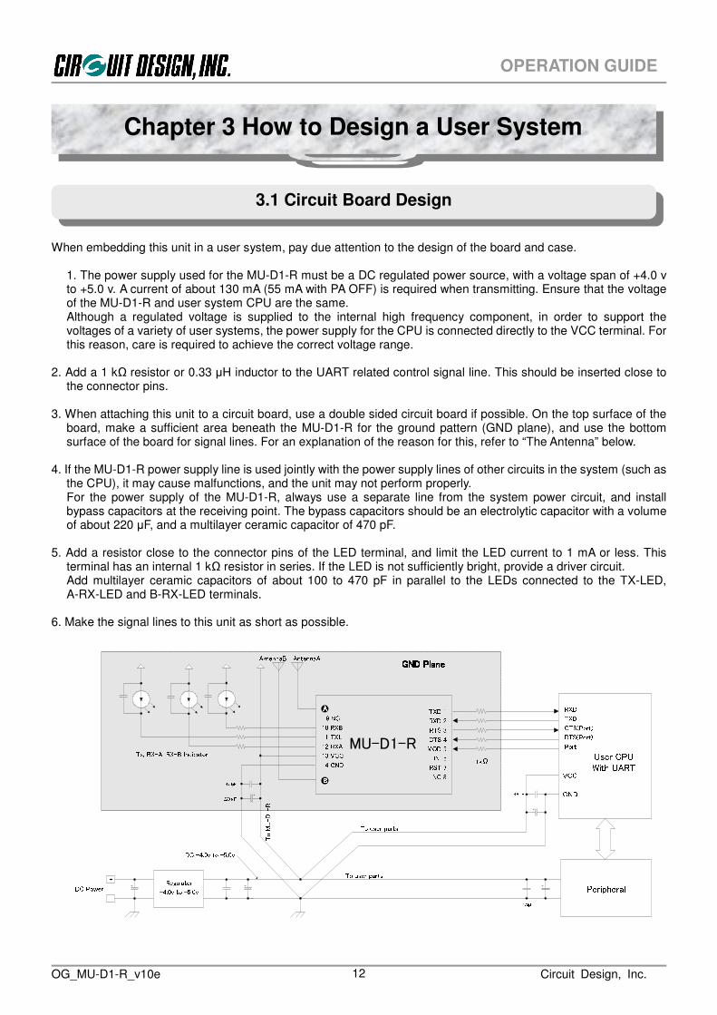
When embedding this unit in a user system, pay due attention to the design of the board and case.
1. The power supply used for the MU-D1-R must be a DC regulated power source, with a voltage span of +4.0 v to +5.0 v. A current of about 130 mA (55 mA with PA OFF) is required when transmitting. Ensure that the voltage of the MU-D1-R and user system CPU are the same. Although a regulated voltage is supplied to the internal high frequency component, in order to support the voltages of a variety of user systems, the power supply for the CPU is connected directly to the VCC terminal. For this reason, care is required to achieve the correct voltage range.
2. Add a 1 kΩ resistor or 0.33 µH inductor to the UART related control signal line. This should be inserted close to
the connector pins. 3. When attaching this unit to a circuit board, use a double sided circuit board if possible. On the top surface of the
board, make a sufficient area beneath the MU-D1-R for the ground pattern (GND plane), and use the bottom surface of the board for signal lines. For an explanation of the reason for this, refer to “The Antenna” below.
4. If the MU-D1-R power supply line is used jointly with the power supply lines of other circuits in the system (such as
the CPU), it may cause malfunctions, and the unit may not perform properly. For the power supply of the MU-D1-R, always use a separate line from the system power circuit, and install bypass capacitors at the receiving point. The bypass capacitors should be an electrolytic capacitor with a volume of about 220 µF, and a multilayer ceramic capacitor of 470 pF.
5. Add a resistor close to the connector pins of the LED terminal, and limit the LED current to 1 mA or less. This
terminal has an internal 1 kΩ resistor in series. If the LED is not sufficiently bright, provide a driver circuit. Add multilayer ceramic capacitors of about 100 to 470 pF in parallel to the LEDs connected to the TX-LED, A-RX-LED and B-RX-LED terminals.
6. Make the signal lines to this unit as short as possible.
3.1 Circuit Board Design
Chapter 3 How to Design a User System
RXDTXDCTS(Port)RTS(Port)Port User CPUWith UARTPeripheralDC +4.0v to +5.0vRegulator+- +4.0v to +5.0vDC Power To MU-D1-R 470pF VCCGND
470pFTo user partsTo user parts
1kΩ220μF470pFAntennaA
Tx, RX-A, RX-B IndicatorAntennaB
MU-D1-R
TXD 1 RXD 2RTS 3CTS 4MOD 5INI 6RST 7NC 8 9 NC10 RXB11 TXL12 RXA13 VCC14 GNDAAAABBBBGND PlaneGND PlaneGND PlaneGND Plane

OG_MU-D1-R_v10e Circuit Design, Inc. 13
OPERATION GUIDE
In systems where a non-directional antenna is required, it is important that the antenna stands vertically in order to exploit communication performance to the maximum. Note that if, for reasons peculiar to the equipment, the antenna must be inside the case, communication performance will be very significantly degraded when handled in the following ways, since these methods contravene antenna theory. It is the responsibility of the user to test performance thoroughly when designing equipment. 1. Putting the antenna inside a metal case 2. Wrapping the antenna around the MU-D1-R itself 3. Locating the antenna beside the ground pattern of your circuit board 4. Fitting the antenna inside by bending it 5. Cutting the antenna to make it shorter 6. Placing the antenna A and B close to each other The antenna of the MU-D1-R is a 915 MHz band 1/4λ whip antenna. Whip antennas are antennas that substitute the ground as one end of a dipole antenna. For this reason the ground plays a very important role. Although the main unit of the MU-D1-R has the function of a ground, in order to exploit its performance fully, connect it to the largest possible ground pattern when mounting the MU-D1-R on your circuit board. The antenna A and B should be kept apart as much as possible. If the antennas are crossed over each other, one may be affected by another and full performance of true diversity may not be reached. In addition, for two-way communication between fixed stations, inclining the whip antenna of the MU-D1-R forwards may increase its communication range. Carry out tests in the specific environment of use.
1. Devise ways of isolating the MU-D1-R as far as possible from sources of noise, including from other embedded equipment. 2. Arrange the MU-D1-R so that it will not be covered by the operator’s hand or the like. 3. The MU-D1-R does not have a waterproof structure. If the antenna is located outside the main unit, use a
structure that prevents water droplets from entering the case.
3.2 The Antenna
3.3 Miscellaneous

OG_MU-D1-R_v10e Circuit Design, Inc. 14
OPERATION GUIDE
4.1.1 Station types and link parameters When performing communication using the MU-D1-R, the source station transmits data towards the target station. To avoid collisions with, and to ensure independence from other systems, it is necessary to set the link parameters to identify the system and each station.
Group ID 01Same areaUI = 0055GI = 01Source stationEI = 01 03Target station02
Group ID 02Group ID 03User ID 0055UI = 0055GI = 0101 EI = 02 UI = 0055GI = 01EI = 03
Destination ID: DIUser ID: UIGroup ID: GIEquipment ID: EIChannel: CH CH = 08 CH = 08 CH = 08Channel 08 Target station
1. The source station and target station
• Source station The station that transmits data • Target station The station that receives data. The target station outputs the received data to the user controller.
2. The link parameter In order to establish communication between the radio stations, it is necessary first to set the link parameters.
• UI: User ID An ID given to the MU-D1-R user for identification of the user. If all the equipment within the user system is not set to the same User ID, no link will be made. • GI: Group ID An ID to identify the group within the user system. Set the same Group ID for all radio stations within the group. • EI: Equipment ID An ID given to each unit for identification of each station. The data transmit command transmits data to the Equipment ID set as the Destination ID • DI: Destination ID Specifies the Equipment ID of the target station. • Channel If all stations in a system are not set to the same channel, no link will be made.
4.1 Communication Concept
Chapter 4 How to Use the MU-D1-R

OG_MU-D1-R_v10e Circuit Design, Inc. 15
OPERATION GUIDE
4.1.2 Basic data transmission
When user data is transmitted from the source station towards the target station using data transmit 1 command, a character string including the data (data receive 1) is output from the target station and processed by the program of the user controller.
Example 1:1 (1:N) system
When the source station 5F transmits the 5 bytes of data ‘ABCDE’ to the target station 01 Usercontroller DI=01 ⑥ Send data
・Initial setting ④ Issue the data transmit command1⑤ Data transmit response ・Target station 01 statusSource stationEI=5F Target stationEI=01 Usercontroller@DT 05 ABCDE CRLF*DT=05 CRLF *DR=05 ABCDE CRLF⑦ Data receive1④ ⑤ ⑦
⑥ Send data③ Set the Destination ID (DI)① Set all stations to the same User ID, Group ID and channel.② Set a different number to each equipment as the Equipment ID(EI)
・Souce station 5F status
4.1.3 The link parameters In order to transmit and receive data, the MU-D1-R has the following link related parameters. Link parameters can be specified easily with commands, and they can be changed each time data is sent. In addition, if the source station and target station do not all use the same channel, no link will be made.
1. UI: User ID, 16-bit, 0000h to FFFEh (0000h is the ID for testing, and FFFFh cannot be used)
The User ID is an ID given to the MU-D1-R user for identification of the user system. Communication is not possible unless all equipment within the user system is set with the same User ID. If a user configures multiple systems, use the Group ID for identification. The User ID setting command is ‘@UI + User ID + password’. The product default User ID is 0000 and this can be used as it is when no particular User ID is required. However, we recommend that you set a User ID to prevent radio interference within a given area. If you require a User ID, please contact Circuit Design, Inc. The 16 User IDs listed in the explanation of User ID command can be used freely.
2. GI: Group ID, 8-bit, 00h to FFh The Group ID is an ID to identify the group within the user system. Set the same Group ID for all equipment within the group. Maintain Group IDs as identification numbers when building other systems. The setting command is ‘@GI’. Please contact Circuit Design, Inc. in cases where use of Group IDs is insufficient and you require other User IDs.
3. EI: Equipment ID, 8-bit, 01h to FFh (FFh is a special operation)
The Equipment ID is an ID for identification of each radio unit. At the source station, enter the Equipment ID of the target station as the Destination ID to which to transmit data. At the target station, the Destination ID included in the received packets is automatically compared with the local station EI. The setting command is ‘@EI’.
4. DI: Destination ID, 8-bit, 00h to FFh (00h and FFh are special operations)
This is used to specify the Equipment ID of the target station. The setting command is ‘@DI’. If 00 (DI = 00h) is specified as the Destination ID and data transmit command 1 is issued, all equipment within the same group receives the data at the same time, irrespective of the Equipment ID (Broadcast). If DI = FFh is specified, the data is sent but no station will receive it.
5. Channel
If all stations in a system are not set to the same channel, no link will be made.

OG_MU-D1-R_v10e Circuit Design, Inc. 16
OPERATION GUIDE
4.1.4 Conditions for establishing a link A link is established for communications when the following conditions are met simultaneously. 1. There are no errors in the received packet 2. The User ID and Group ID match 3. The Equipment ID specified as the Destination ID and the Equipment ID of the target station match 4. The channel used is the same

OG_MU-D1-R_v10e Circuit Design, Inc. 17
OPERATION GUIDE
The MU-D1-R can be used for building 1:1, 1:N, and N:N systems. Several systems can be operated within the same area by separating the channels used. Equipment IDs from 01h to FEh can be specified, and a maximum of 254 MU-D1-R units can be connected in 1 group.
4.2.1 Communication within a group (1:N and N:N systems) Set the same User ID and Group ID for one group. If the Destination ID specified at the source station and the Equipment ID of the target station match, data (data receive 1) is output from the target station. The diagram below shows a 1:N system, although it is also possible to build an N:N system in which all the units have an equal relationship.
Communication between groups By changing the Group ID for transmitting, it is possible to communicate with another group.
Broadcast communication If the Destination ID is specified as 00h at the source station and data is transmitted, all target stations will receive the data at the same time, irrespective of the Equipment ID.
4.2 System Configuration
Group1(1:N system)Same areaGroup2(1:N system)Group3 (1:N system)UI = 0055GI = 01EI=02UI = 0055GI = 01EI=03UI = 0055GI = 01EI=04UI = 0055GI = 01EI=01
Note: UI = User ID G = Group ID EI = Equipment IDDI=01DI=02DI=03DI=01DI=04DI=01MUD1-RS2 MUD1-RS2MUD1-RS2MUD1-RS2
UIEIEI EIEIEIEI EIEI GI=8EIEI EIEI※All equipment in the system has the same frequency channel.※Communication is not possible between different Group IDs.
EIEI EIEI GI=1GI=1GI=1 UI User ID 2bytesItem name Size 0000-FFFE Set a passwordID value ContentGI Group ID 1byte 00~FF No. 0 to 255EI Equipment ID 1byte 01~FE No. 1 to 254※Group ID and Equipment ID can be set freely within the range above.

OG_MU-D1-R_v10e Circuit Design, Inc. 18
OPERATION GUIDE
Note
The MU-D1-R has the following 3 modes.
1. Command mode (standard mode) 2. Text mode (for testing) 3. Binary mode (for testing)
Transmitting and receiving data is usually performed in the command mode. Use this mode when you build your system. The text mode and binary mode are provided as testing modes, however you can also make applications within the range of these functions.
When configuring your system, ensure that the source station and target station are in the same mode.
4.3.1 Command mode This is the basic mode for sending and receiving user data by radio. The MU-D1-R commands consist of commands for transmitting and receiving data, and commands for control of the parameters of the MU-D1-R unit itself. Changing the parameters, mode, and channel of the main unit cannot be performed in the binary mode or text mode. Consider how to enable mode switching at the hardware design stage. Control of the radio component is performed automatically by the MU-D1-R, so you do not need to pay attention to this aspect. 255 bytes of user data can be sent at one time. For transmission of user system data, the data transmit command 1 is used. When the MU-D1-R receives data, since only correctly received data is output to the user application as a data receive, it is processed on the user side properly.
4.3.2 Text mode (for testing) This mode is used to check operation using RS232C communication software (HyperTerminal and the like) on a PC. Text data can be input and output directly. This mode is convenient for transmitting and receiving characters entered using a keyboard. Always add the CRLF code as a terminator at the end of the character string. When the MU-D1-R detects this terminator, it starts data transmission. Ensure that the maximum number of characters input is within 255 bytes. The CRLF code (0Dh, 0Ah) and Esc code (1Bh) cannot be sent by radio. However, the CRLF code is attached to the end of the data output from the target station as a terminator.
4.3.3 Binary mode (for testing) This mode is used to check operation using RS232C communication software (HyperTerminal and the like) on a PC. All 8-bit codes (00h to FFh) can be transmitted and received as data. 225 bytes of binary data can be input or output directly at one time. The input character string (max. 255 characters) is buffered until the buffer is filled with 255 characters, or until the value set for the period during which no data is input is reached, and the character string is framed and transmitted. The setting for the period during which no data is input is performed with the ‘@TB’ command.
4.3 Modes

OG_MU-D1-R_v10e Circuit Design, Inc. 19
OPERATION GUIDE
4.3.4 Mode setting When the MODE terminal is at High level The MU-D1-R is set to the command mode irrespective of the setting in the mode register. The recommended operation mode of the MU-D1-R is the command mode. When setting the MODE terminal to Low to switch to other modes, preset the mode register. When the MODE terminal is at Low level 1. In the command mode if the ‘@MD TX’ command is issued, the MU-D1-R mode register is set to ‘TX’, which is the
text mode. Issuing the ESC code returns from the text mode to the command mode. 2. In the command mode if the ‘@MD BI’ command is issued, the MU-D1-R mode register is set to ‘BI’, which is the
binary mode. To switch from the binary mode to the command mode, turn off the power supply of the MU-D1-R briefly or reset the hardware. If the BI mode is fixed in the EEPROM using the command option ‘/W’, the MU-D1-R cannot be set to the command mode without initializing it. To initialize the MU-D1-R, set the INI terminal to Low and turn on the power, and after turning off the power briefly, set the INI terminal to High and turn on the power again.
3. By setting the MODE terminal to High level, the MU-D1-R can be set to the command mode whatever the setting
in the MU-D1-R mode register (irrespective of the current mode).
Mode relationship diagram
Mode terminal level High
Low Low@MDTX
MOD terminalLow@MDCD
MOD terminalLow@MDBI
MOD terminal
MOD terminal
HighMOD terminal
HighMOD terminal
HighCommand modeBinary mode Text mode
Command mode@MDTX@MDBI1, Reset (RST terminal) *12, Initialize (INI terminal) *2*1: When the mode is set in the RAM *2: When the mode is fixed in the EEPROM
Mode RegisterBI CD TX1, Issue the ESC code2, Reset (RST terminal) *13, Initialize (INI terminal) *2
* BI: Binary mode CD: Command mode TX: Text mode
* The brackets ( ) in the diagram indicate use of an RS232C driver. When using HyperTerminal, the DTR line is always at H level and the MODE terminal is at L level.

OG_MU-D1-R_v10e Circuit Design, Inc. 20
OPERATION GUIDE
If you are uncertain about the various settings of the MU-D1-R, return them to the settings at the time the power was turned on. The internal CPU is reset by any of the following.
1. Set the reset (RST) terminal of the MU-D1-R to 1 ms period Low level. 2. Issue the software reset command ‘@SR’. 3. The target station can be reset using an extended command.
Return the unit to the factory default settings if communication with the MU-D1-R is not possible or if you are uncertain of the internal settings. The internal CPU is initialized with any of the following.
1. Set the INI terminal of the MU-D1-R to Low level and turn on the power. Then turn off the power, and after setting to the INI terminal to open, turn it on again. 2. Issue the initialize command ‘@IZ’. After issuing it, always issue the software reset command ‘@SR’.
After initialization, the main parameter values (default values) are as follows. For details of the default values, refer to the relevant command in the manual.
1. Link parameters
User ID: UI = 0000, Group ID: GI = 00, Equipment ID: EI = 01, Destination ID: DI = 01, Channel = 1 channel 2. UART parameters
Baud rate = 19,200 bps, parity = none, stop bit = 1, data length = 8 bits 3. Internal operation parameters
Mode = command
The MU-D1-R is equipped with a power amplifier switching function which can switch the antenna power (output power) between 40 mW and 8 mW. This is useful for setting the antenna power according to the required operation range and conditions. To switch the power amplifier, issue the ‘@PA’ command.
4.6 Power amplifier On/Off setting
4.4 Resetting
4.5 Initializing

OG_MU-D1-R_v10e Circuit Design, Inc. 21
OPERATION GUIDE
When the source station MU-D1-R receives a command from the user controller, it returns a command response to the user controller as an acknowledgment of command receipt. At the same time, it performs processing corresponding to the command. The commands, responses and receives the MU-D1-R uses are as follows.
Data receive1
※1 Command response types・Data transmit response ・Control response ・Monitor response・Test responseError responseData transmit command
Sourcestation TargetstationMonitor commandControl CommandCommand response※1Receive response
ReceiveCommandsResponsesTest commandData transmit command1
* The command response is a command receipt response corresponding to the issued command. Command issued Command responses Data transmit command → Data transmit response Control command → Control response Monitor command → Monitor response Test command → Test response
Chapter 5 Commands, Responses and Receives
5.1 About the Command, Response and Receive

OG_MU-D1-R_v10e Circuit Design, Inc. 22
OPERATION GUIDE
1. Data transmit command, data transmit response and data receive
The data transmit command is a command to transmit user data from the source station. The target station outputs a data receive. Example Data transmit command 1 ( For 1:1 and 1:N systems) Source station side SourcestationUsercontroller *DT=05@DT 05 ABCDE① Data transmit command1② Data transmit response Target station side UsercontrollerTargetstation③ Send data ④ Data receive1*DR=05 ABCDE
2. Control command and control response
Commands and responses for controlling the various operations of the MU-D1-R. Example Change CH to 05(05h)
① Control command③ Control responseSource station side@CH 05 *CH=05 ② Change to 05(05h)chSourcestationUsercontroller
3. Monitor command and monitor response
Commands and responses for performing the various monitoring functions. Example Source station side SourcestationUsercontroller ② Check the RSSI level*RA=50@RA① Monitor command③ Monitor response
4. Test command and test response
Commands and responses for performing the various test functions. 5. Receive response
When issuing the monitor command, processing is performed at the target station and the result is returned to the source station. This processing result is output from the source station as a receive response.
6. Error response A response returned if there are errors in the format of the transmit command, control command and so on.

OG_MU-D1-R_v10e Circuit Design, Inc. 23
OPERATION GUIDE
* In the table below, xx and XX, and XXXX are 2 and 4 digit hex values respectively. w indicates ASCII characters or byte data.
5.2.1 Data transmit command and data transmit response
Command name Command format Data transmit
response format (Command response)
Reference page
Data transmit command 1 @DT XX ww...ww *DT = XX
5.2.2 Data receive A receiving data output from the target station. Note that the data receive character string depends on the data transmit command issued from the source station.
Receive name Receive format Corresponding command Reference
page
Data receive 1 *DR = XX ww...ww Data transmit command 1 (@DT)
5.2.3 Control commands and control responses
Command type Command name Command format Control response format (Command response)
Reference page
User ID setting @UI XXXX,XXXX *UI = XXXX
Group ID setting @GI XX *GI = XX
Equipment ID setting @EI XX *EI = XX
Destination ID setting @DI XX *DI = XX
Radio link related setting and acquisition
commands
Channel setting @CH XX *CH = XX
UART baud rate setting @BR ww *BR = ww
UART parity setting @PB ww *PB = ww UART parameter
setting commands
UART stop bit setting @SB ww *SB = ww
Operation mode setting @MD ww *MD = ww Command mode input waiting time setting
@TC XX *TC = XX
Time without input in the binary mode setting
@TB XX *TB = XX
Response display mode setting @RM ww *RM = ww Program version acquisition @VR *VR = XX ww...ww Serial number acquisition @SN *SN = wwwwwwwww Reset @SR *SR = 00 Initialize @IZ *IZ = 00 Power amplifier On/Off setting @PA ww *PA = ww
Operation setting and information
acquisition commands
Antenna power setting @PW ww *PW = ww
5.2 Command, Response and Receive Table

OG_MU-D1-R_v10e Circuit Design, Inc. 24
OPERATION GUIDE
5.2.4 Monitor commands and monitor responses
Command name Command
format Monitor response format
(Command response) Response
type Reference
page
RSSI absolute level measurement @RA *RA = XX No response
All channel RSSI absolute level measurement @RC *RC = XX...XX No response
*RSSI: Received Signal Strength Intensity
5.2.5 Test commands and test responses
Command name Command format Test response format (Command response)
Response type
Reference page
Test data continuous transmission @CT ww *CT = ww No response
Packet test @CP XX ww...ww *CP = XX Receive response
5.2.6 Receive response
When issuing the monitor command, processing is performed at the target station and the result is returned to the source station. This processing result is output from the source station as a receive response. The content of the receive response depends on the command issued. For details, refer to the explanation of the relevant command.
5.2.7 Error response A response returned if there are errors in the format of the transmit command, control command and so on.
By specifying the option ‘/W’ as continuation of a command, command values can be fixed in the EEPROM within the MU-D1-R. The next time the power is turned on, the contents of the EEPROM are set to the initial values. The time required for conversion is 55 ms.
The commands that can specify the option ‘/W’ are as follows.
BR, CH, CT, DI, EI, GI, MD, PB, RM, TC, TB, UI, PA Example: Fix the User ID as 0000h (UI=0000 is for testing)
Control command: @UI 0000,0B27 /W CRLF Control response: *WR = PS CRLF
*UI = 0000 CRLF
Example: Set the channel to ch 16 and fix it.
Control command: @CH 10 /W CRLF Control response: *WR = PS CRLF
*CH = 10 CRLF
5.3 Save Setting Command Options

OG_MU-D1-R_v10e Circuit Design, Inc. 25
OPERATION GUIDE
Note
1. The command parameter is applied immediately after the command to change it is issued. In particular, note that if the UART related parameters are changed, communication will not be possible unless the UART parameters on the control side are also changed.
2. The maximum number of EEPROM conversions is 100,000. Do not design a program which needs to be rewritten repeatedly.
3. Do not issue other commands during conversion of the EEPROM.

OG_MU-D1-R_v10e Circuit Design, Inc. 26
OPERATION GUIDE
The default value In the explanation below, “Default” value is the factory setting set using the ‘INI’ terminal or by
issuing the initialize command.
The terminator In the explanation below, the terminator, which is the characters that indicate the end of the command and response, is the symbol ‘CRLF’. ‘CRLF’: CR (carriage return: ‘CR’ = 0Dh) + LF (line feed: ‘LF’ = 0Ah)
5.4.1 Data transmit command, response and data receive
Data transmit command basic format
Prefix + command name + value + data + command option + terminator Prefix: ‘@’=40h, a code that indicates the start of the command string. Command name: The 2 ASCII characters ‘DT’. Specified with upper case or lower case characters. Value: Specifies user data size with a hexadecimal number. Data: Byte sequence of user data. Command option: Specifies the operation of the command. Data transmit command code (Transmission of 6-byte data)
Command string Hexadecimal code actually sent to the MU-D1-R @DT 06 abc123 CRLF 40,44,54,30,36,61,62,63,31,32,33,0D,0A
Data transmission response basic format
Prefix + command name + ‘=’ + value + terminator Prefix: ‘*’ = 2Ah, a code that indicates the start of the response string. Command name: The ASCII characters ‘DT’. Value: The size of data received with the ‘DT’ command
Data transmit response code (255-byte data transmission)
Transmit response character string Hexadecimal code actually issued from the MU-D1-R *DT = FF CRLF 2A,44,54,3D,46,46,0D,0A
Data receive basic format
Prefix + data receive name + ‘=’ + value 1 + value 2 + data + option data + terminator
Prefix: ‘*’ = 2Ah, a code that indicates the start of the response string. Data receive name: The 2 ASCII characters ‘DR’’. Value 1: 1 byte hexadecimal value to show the RSSI information. Specified by 2 ASCII characters. Value 2: 1 byte hexadecimal value to show the size of the user data. Specified by 2 ASCII characters. Data: Byte sequence of user data. Option data: Route information and the like. Data receiver code
Data receive (receiving data) character string Hexadecimal code actually returned from the MU-D1-R
*DR = 06 abc123 CRLF 2A,44,52,3D,30,36,61,62,63,31,32,33,0D,0A
5.4 Command, Response and Receive details

OG_MU-D1-R_v10e Circuit Design, Inc. 27
OPERATION GUIDE
5.4.1.1 @DT Data transmit command 1 The data transmit command 1 ‘@DT’ is a command to transmit data towards the target station set as the Destination ID at the source station.
When the source station MU-D1-R receives the command from the user controller, it returns a command response as acknowledgment of receipt of the command. At the same time, it starts wireless data transmission. The target station MU-D1-R outputs the data receive 1 in the ‘*DR’ format.
Format: ‘@’ + ‘DT’ + data size + data + ‘CRLF’ Data size is specified by 2 hexadecimal ASCII characters. The maximum data size that can be sent at one time
is 255 bytes. The data is a numerical value up to 00h to FFh. The data is sent to the target station set in the Destination ID: ‘@DI’
Format ‘@DT’ ss DD....D ‘CRLF’
ss: Shows the data size in 2 hexadecimal digits Value: 00h to FFh DD...D: D expresses 1-byte data. Value: 00h to FFh, amount of data: maximum 255 bytes
Example: Transmit the 10 bytes of data (0Ah) ‘0123ABC%#$’ to the target station set in the Destination ID.
The target station Equipment ID = 01h. The source station Equipment ID = 5Fh. Usercontroller DI=01 ③ Send data
・Source station 5F status① Issue the data transmit command1:② : Data transmit response ・Target station 01 statusSourcestationEI=5F TargetstationEI=01 Usercontroller@DT 0A 0123ABC%#$ CRLF*DT = 0A CRLF *DR = 0A 0123ABC%#$ CRLF④ Data receive1:① ② ④
③ Send data Data receive 1 (Target station output)
Example: Receives 5-byte user data (05h) ‘ABCDE’
Source station = 01, when the received signal level is -69 dBm (45h)
Data transmit command 1: @DT 05 ABCDE CRLF
*DR = 05 ABCDE CRLF (default)

OG_MU-D1-R_v10e Circuit Design, Inc. 28
OPERATION GUIDE
Note
5.4.2 Control commands and control responses
Command basic format
Prefix + command name + value + terminator Prefix: ‘@’=40h, a code that indicates the start of the command string. Command name: 2 ASCII characters. Specified with upper case or lower case characters. Value: Value corresponding to the relevant command. Terminator: A code that indicates the end of the command ‘CRLF’ (0Dh, 0Ah). Control command code
Command string Hexadecimal code actually sent to the MU-D1-R @ CH 0DCRLF 40,43,48,30,44,0D,0A
Response basic format
Prefix + command name + ‘=’ + value + terminator Prefix: ‘*’ = 2Ah, a code that indicates the start of the response string. Command name: 2 ASCII characters for the received command. Value: Result value corresponding to the relevant command. Terminator: A code that indicates the end of the command ‘CRLF’ (0Dh, 0Ah). Command response code
Response character string Hexadecimal code actually returned from the MU-D1-R * CH = 0D CRLF 2A,43,48,3D,30,44,0D,0A
The command parameter is applied immediately after the command to change it is issued. In particular, note that if the UART related parameters are changed, communication will not be possible unless the UART parameters on the control side are also changed.
5.4.2.1 @BR UART baud rate setting Sets the UART baud rate. The change of setting is applied immediately after the response to the command is returned. Change the baud rate on the control side immediately. Default: 19 Value: 19 = 19,200 bps 38 = 38,400 bps 57 = 57,600 bps Example: Change to 57,600 bps
Control command: @BR 57 CRLF Control response: * BR = 57 CRLF
Note:Make sure to wait for more than 200 ms before issuing the next command just after the baud rate is changed.
5.4.2.2 @CH Frequency channel setting
Sets the channel to be used. Specify the channel following ‘@CH’ with 2 ASCII (hexadecimal) characters. Default: 01h Value: 01h - 14h (hexadecimal value that indicates channels 1 to 20) Example: Change the channel to 15 (0Fh)
Control command: @CH 0F CRLF
Control response: When RM = CD * CH = 0F CRLF
When RM = TX * CH =0F : 920.5 MHz CRLF

OG_MU-D1-R_v10e Circuit Design, Inc. 29
OPERATION GUIDE
5.4.2.3 @DI Destination ID setting Sets the destination (target station). Refer also to the explanation of User ID and Group ID. If 00 is specified as the Destination ID, all equipment within the same group will receive the data at the same time (broadcast function). If FFh is set, the data is sent but no station will receive it. Default: 01h Value: 00h to FFh (00h and FFh are special operations)
Example: Change the Destination ID to 25h Control command: @DI 25 CRLF Control response: *DI = 25 CRLF
5.4.2.4 @EI Equipment ID setting
Sets the Equipment ID. One group can contain 254 units. Refer also to the explanation of User ID and Group ID. The Equipment ID 00h is used for the broadcast function, and there is no reason for setting it. If the Equipment ID FFh is specified, data will not be received. In this case, if the ‘@RA’ command is used, only RSSI level data is output. Default: 01h Value: 01h to FFh (FFh is a special operation) Example: Change the Equipment ID to 34h
Control command: @EI 34 CRLF Control response: *EI = 34 CRLF
5.4.2.5 @GI Group ID setting Sets the Group ID. Refer also to the explanation of the User ID. There are 256 Group IDs. Maintain these IDs for use as identification numbers when building other user systems. Default: 00h Value: 00h – FFh Example: Change the Group ID to 34h
Control command: @GI 34 CRLF Control response: *GI = 34 CRLF
5.4.2.6 @IZ Initialize Returns the MU-D1-R to the factory default values. The content of the EEPROM fixed with the ‘/W’ option is also initialized. For default values, refer to the relevant command. After using this command, always execute the SR command. Example:
Control command: @IZ CRLF
Control response from the MU-D1-R: When RM = CD *IZ = 00 CRLF
When RM = TX *IZ = 00 : ROM was initialized. CRLF
5.4.2.7 @MD Operation mode register setting Sets the MU-D1-R operation mode register. The mode is determined in accordance with the status of the MODE terminal. For details, refer to the item “Modes”. No commands can be used except in the command mode (CD). Default: CD Value: CD: Command mode TX: Text mode BI: Binary mode Example 1: Change to the text mode
Control command: @MD TX CRLF Control response: *MD = TX CRLF
Example 2: Change to the binary mode
Control command: @MD BI CRLF Control response: *MD = BI CRLF
OG_MU-D1-R_v10e Circuit Design, Inc. 30
OPERATION GUIDE
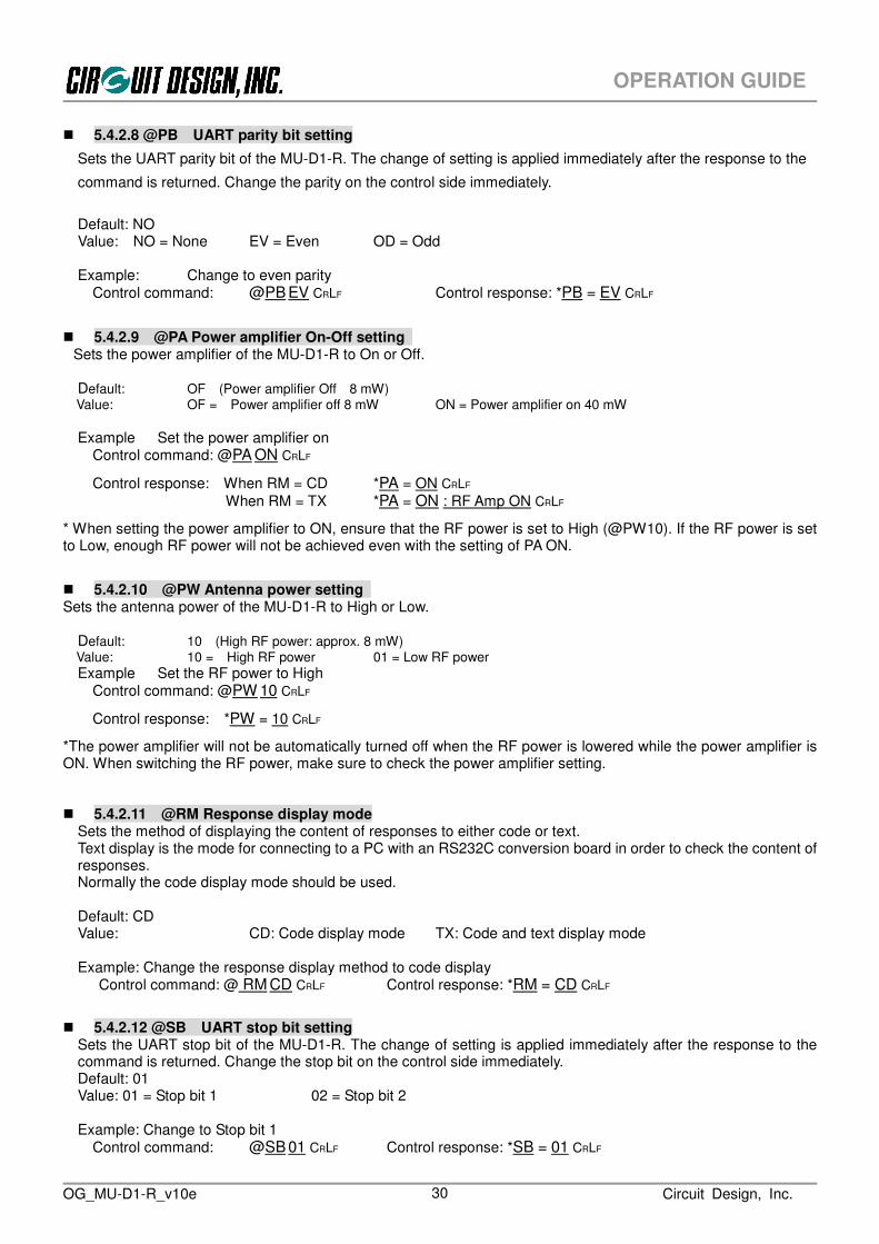
5.4.2.8 @PB UART parity bit setting
Sets the UART parity bit of the MU-D1-R. The change of setting is applied immediately after the response to the
command is returned. Change the parity on the control side immediately.
Default: NO Value: NO = None EV = Even OD = Odd Example: Change to even parity
Control command: @PB EV CRLF Control response: *PB = EV CRLF
5.4.2.9 @PA Power amplifier On-Off setting
Sets the power amplifier of the MU-D1-R to On or Off.
Default: OF (Power amplifier Off 8 mW) Value: OF = Power amplifier off 8 mW ON = Power amplifier on 40 mW
Example Set the power amplifier on
Control command: @PA ON CRLF
Control response: When RM = CD *PA = ON CRLF
When RM = TX *PA = ON : RF Amp ON CRLF
* When setting the power amplifier to ON, ensure that the RF power is set to High (@PW10). If the RF power is set to Low, enough RF power will not be achieved even with the setting of PA ON.
5.4.2.10 @PW Antenna power setting Sets the antenna power of the MU-D1-R to High or Low.
Default: 10 (High RF power: approx. 8 mW) Value: 10 = High RF power 01 = Low RF power
Example Set the RF power to High Control command: @PW 10 CRLF
Control response: *PW = 10 CRLF
*The power amplifier will not be automatically turned off when the RF power is lowered while the power amplifier is ON. When switching the RF power, make sure to check the power amplifier setting. 5.4.2.11 @RM Response display mode
Sets the method of displaying the content of responses to either code or text. Text display is the mode for connecting to a PC with an RS232C conversion board in order to check the content of responses. Normally the code display mode should be used. Default: CD Value: CD: Code display mode TX: Code and text display mode Example: Change the response display method to code display
Control command: @ RM CD CRLF Control response: *RM = CD CRLF
5.4.2.12 @SB UART stop bit setting Sets the UART stop bit of the MU-D1-R. The change of setting is applied immediately after the response to the command is returned. Change the stop bit on the control side immediately. Default: 01 Value: 01 = Stop bit 1 02 = Stop bit 2 Example: Change to Stop bit 1
Control command: @SB 01 CRLF Control response: *SB = 01 CRLF

OG_MU-D1-R_v10e Circuit Design, Inc. 31
OPERATION GUIDE
5.4.2.13 @SN Show serial number
Shows the serial number of the MU-D1-R. The serial number is the 9-digit control number shown on the label of the main unit. The response from the MU-D1-R is in ASCII characters. Example:
Control command: @SN CRLF Control response: *SN = A12345678 CRLF 5.4.2.14 @SR Reset
Returns the MU-D1-R to the status when the power is turned on. The MU-D1-R starts up with the fixed content of the EEPROM with the ‘/W’ option. The command response for the ‘SR’ command is issued immediately after the command is received. The time during which commands cannot to be received is 120 ms when the ‘@SR’ command is issued and 100 ms when the hardware is reset at the INI terminal. Example:
Control command: @SR CRLF Control response: When RM = CD *SR = 00 CRLF
(When RM = CD *SR = 00: Software reset was performed. CRLF)
5.4.2.15 @TB Time without input in the binary mode setting
In the binary mode, if the status where no UART data is input continues beyond the set time, transmission of data in the buffer starts automatically. Calculate the setting value with 32 ms per 1 count. Default: 10h (16 × 32 = 0.512 s) Value: 01h to FFh: 1 count = 32 ms Example: Set the time to 20h (1.02 s)
Control command: @TB 20 CRLF Control response: *TB = 20 CRLF
5.4.2.16 @TC Command mode input waiting time
If command input is not completed within the time set, the character string input so far is cleared and the unit returns to the input waiting status. Calculate the setting value with 0.5 s per 1 count. Default: 00h (No limit for input time) Value: 00h – FFh Example: Set waiting time to 0Ah (10 x 0.5 s = 5 s)
Control command: @TB 0A CRLF Control response: *TC = 0A CRLF
5.4.2.17 @UI User ID setting
User IDs are IDs (about 30,000) that are meant to prevent data interference with other systems within a given area, and if all the equipment within the same user system does not have the same ID, communication cannot be established. The link parameters derive from the User ID, Group ID, Equipment ID, and Destination ID. All MU-D1-R units have a default User ID of 0000h, and they can be used with this value, but to avoid data collision with other users in the same area, we recommend that you set a User ID other than 0000h for actual operations with the MU-D1-R. If a unique User ID is required, we will provide it along with a password. Please contact Circuit Design, Inc directly. Please ensure that you do not lose your User ID and password (we also maintain records of this information).
*About 30,000 User IDs are ensured, but there may be duplicates if the IDs should be required in excess of this range. In other words, the User ID does not guarantee the security of data. However since it is not likely that more than 30,000 User IDs are issued and there is also a very small possibility of overlapping in the same area, you can use it at ease. A password is required for setting a User ID, but the passwords for the following 16 User IDs are publicly available so they can be used freely. The password follows the User ID in brackets. 0000 (0B27), EFF1 (4E74), EFF2 (D18E), EFF3 (5909), EFF4 (82B5), EFF5 (9D47), EFF6 (E4D1), EFF7 (3B2F), EFF8 (B3A6), EFF9 (6C5A),

OG_MU-D1-R_v10e Circuit Design, Inc. 32
OPERATION GUIDE
EFFA (C6F7), EFFB (7F6F), EFFC (15C4), EFFD (0A34), EFFE (F7E8), EFFF (A09C) Default: 0000h Value: 0000h to FFFEh (0000h is for testing, FFFFh cannot be used)
Example: Set the User ID to 0000h with the password 0B27h provided.
Control command: @UI 0000,0B27 CRLF Control response: *UI = 0000 CRLF
* For ordinary applications, fix the UI, GI, and EI in the EEPROM with the command /W option. * Please contact the distributor or Circuit Design, Inc. if you require multiple User IDs.
5.4.2.18 @VR Display program version
Obtains the program version of the MU-D1-R. Example:
Control command: @VR CRLF
Control response: *VR = 20 Ver2.0F-HP 2010/05/26 14:22 CRLF
5.4.3 Monitor commands and Responses 5.4.3.1 @RA RSSI absolute value measurement Measures the absolute value for Received Signal Strength Intensity (RSSI) of the antenna A and B at the channel set. The measured value is a hexadecimal value that indicates the RSSI absolute value. The code of the RSSI value acquired is minus.
Format 1: ‘@’ + ‘RA’ + ‘CRLF’ Details
Format: ‘@RA CRLF’
Range of the hexadecimal value that indicates the RSSI absolute value: 00h to FFh
Example: Measure the RSSI absolute value of the current channel
Monitor command: @RA CRLF
Monitor response:
When RM = CD *RA 63 65 CRLF
*63h=99:RSSI absolute value of the antenna A, 65h=101:RSSI absolute value of the antenna B
(When RM = TX *RA = 63 -99dBm , 65 -101dBm CRLF)
5.4.3.2 @RC All channel RSSI absolute level measurement Measures the RSSI (Received Signal Strength Intensity) over all channels. It is possible to check the floor noise level of the field, third party field level, and field level of the system itself. The measured values of the antenna A and B are alternately output as a 2-digit hexadecimal number in ASCII characters that express the absolute value for RSSI. The code of the RSSI value acquired is minus.
Format 1: ‘@’ + ‘RC’ + ‘CRLF’ Details
Format: ‘@RC CRLF’
Range of the hexadecimal value that indicates the RSSI absolute value: 00h to FFh
Example: Measure the RSSI absolute value over all channels
Monitor command: @RA CRLF
Monitor response: *RC = 7A7C7D……….7E7D CRLF
*A response is returned for 20 ch x 2 antennas of RSSI data (80- byte ASCII characters)
OG_MU-D1-R_v10e Circuit Design, Inc. 33
OPERATION GUIDE
*The code is minus. Example: 6A=-106 dBm
*The response is returned in the order like Antenna A of Ch 1, Antenna B of Ch 1, Antenna A of Ch 2, Antenna
B of Ch 2…….
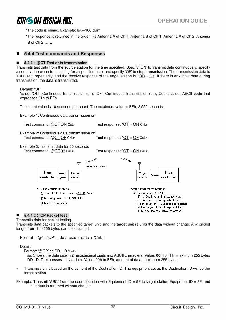
5.4.4 Test commands and Responses 5.4.4.1 @CT Test data transmission Transmits test data from the source station for the time specified. Specify ‘ON’ to transmit data continuously, specify a count value when transmitting for a specified time, and specify ‘OF’ to stop transmission. The transmission data is ‘CRLF’ sent repeatedly, and the receive response of the target station is ‘*DR = 00’. If there is any input data during transmission, the data is transmitted.
Default: ‘OF’ Value: ‘ON’: Continuous transmission (on), ‘OF’: Continuous transmission (off), Count value: ASCII code that expresses 01h to FFh The count value is 10 seconds per count. The maximum value is FFh, 2,550 seconds. Example 1: Continuous data transmission on
Test command: @CT ON CRLF Test response: *CT = ON CRLF Example 2: Continuous data transmission off
Test command: @CT OF CRLF Test response: *CT = OF CRLF
Example 3: Transmit data for 60 seconds Test command: @CT 06 CRLF Test response: *CT = ON CRLF
④ Data receive *DR=00・Source station 5F status① Issue the test command @CT 06 CRLF② : Test response *CT=ON CRLF ・Status of all target stations② ④ UsercontrollerUsercontroller TargetstationSourcestation③ Transmit test data
① ③ Transmit test data・If the Destination ID matches, data receive is output for specified time.・To measure the RSSI of the test signal, set the target station Equipment ID to ‘FFh’ and use the ‘@RA’command.
5.4.4.2 @CP Packet test Transmits data for packet testing. Transmits data packets to the specified target unit, and the target unit returns the data without change. Any packet length from 1 to 255 bytes can be specified.
Format : ‘@’ + ‘CP’ + data size + data + ‘CRLF’ Details
Format: ‘@CP’ ss DD....D ‘CRLF’ ss: Shows the data size in 2 hexadecimal digits and ASCII characters. Value: 00h to FFh, maximum 255 bytes DD...D: D expresses 1-byte data. Value: 00h to FFh, amount of data: maximum 255 bytes
Transmission is based on the content of the Destination ID. The equipment set as the Destination ID will be the
target station.
Example: Transmit ‘ABC’ from the source station with Equipment ID = 5F to target station Equipment ID = 8F, and the data is returned without change.

OG_MU-D1-R_v10e Circuit Design, Inc. 34
OPERATION GUIDE
Receive response (Source station output)
The packet data sent to the target station is returned without change and output as the receive response.
• Source station output *DR = 03 ABC CRLF
5.4.5 Receive response When issuing the monitor command, processing is performed at the target station and the result is returned to the source station. This processing result is output from the source station as a data receive. The content of the receive response depends on the command issued. For details, refer to the explanation of the relevant command.
5.4.6 Error response If there is an error in the format of the transmit command or control command issued, an error code of the type shown below is sent in response. These error codes are required during product development, but you should ensure that errors do not occur with your product. It is possible to change the display format by issuing the response display mode setting command ‘@RM = TX’ or ‘@RM = CD’. In the default settings, only error codes are displayed.
Format: Prefix + response name + ‘=’ + value + terminator
Prefix: ‘*’ = 2Ah, a code that indicates the start of the response string. Response name: The 2 ASCII characters ‘ER’. Value: Error code shown in the error code list. Terminator: A code that indicates the end of the command ‘CRLF’ (0Dh, 0Ah).
Error response code Response character string Hexadecimal code actually returned from the MU-D1-R
*ER = 1D CRLF 2A,45,52,3D,31,44,0D,0A
Example: Error response when the ‘@BR’ command is issued 1. When the command ‘@RM = CD’ is issued
*ER = 0A CRLF 2. When the command ‘@RM = TX’ is issued
*ER = 0A : BR command format error CRLF

OG_MU-D1-R_v10e Circuit Design, Inc. 35
OPERATION GUIDE
Error code list Code Description Meaning 01 Issued command is not found The issued command does not exist 02 Channel data error The specified channel is outside the range 03 CH command error Use a 2-digit Hex character for the ‘CH’ command 04 CH command format error The ‘CH’ command format is wrong 05 DT command error Use a 2-digit Hex character for the ‘DT’ command 06 DT command format error The ‘DT’ command format is wrong. Check the data size. 07 - 08 RA command format error The ‘RA’ command format is wrong 09 RM command format error The ‘RM’ command format is wrong 0A BR command format error The ‘BR’ command format is wrong 0B - 0C MD command format error The ‘MD’ command format is wrong 0D DI command error Use a 2-digit Hex character for the ‘DI’ command 0E DI command format error The ‘DI’ command format is wrong 0F EI command error Use a 2-digit Hex character for the ‘EI’ command 10 EI command format error The ‘EI’ command format is wrong 11 TC command format error The ‘TC’ command format is wrong 12 TB command format error The ‘TB’ command format is wrong 13 Command input time exceeds limit The time limit for inputting the command was exceeded 14 - 15 CT command format error The ‘CT’ command format is wrong 16 - 17 UI command error Use a 4-digit Hex character for the ‘UI’ command 18 UI command format error The ‘UI’ command format is wrong 19 - 1A PB command format error The ‘PB’ command format is wrong 1B SB command format error The ‘SB’ command format is wrong 1C - 1D - 1E - 1F IZ command format error The ‘IZ’ command format is wrong 20 SR command format error The ‘SR’ command format is wrong 21 - 22 SN command format error The ‘SN’ command format is wrong 23 - 24 SY command format error The ‘SY’ command format is wrong 25 RC command format error The ‘RC’ command format is wrong 26 - 27 - 28 - 29 RA command format error The ‘RA’ command format is wrong 2A - 2B - 2C - 2D - 2E - 2F - 30 - 31 - 32 - 33 - 34 - 35 PA command format error The “PA” command format is wrong Caution: The error codes for the CP command are the DT command errors 05 and 06.

OG_MU-D1-R_v10e Circuit Design, Inc. 36
OPERATION GUIDE
Control of the MU-D1-R is performed by issuing commands and processing the subsequent response (including the data receive at the target station). The MU-D1-R has 3 modes, however the only mode required for making practical applications is the command mode. This chapter explains the items necessary for developing a user program, focusing on the command mode.
The purpose of the MU-D1-R is to provide the basic components for communication in order to enable various types of equipment to use radio. For this reason it is necessary to build communication protocols (ARQ, MCA and so on) into the user application in accordance with the particular application. *ARQ: Automation Repeat request MCA: Multi-Channel Access
The outline of how the user controls the MU-D1-R is explained using one-way communication as an example.
Includes link parameters*Issuing @DT commands:・Enter the EI of the target station in the DI and issue the DT command. *DR response receive processing 1. The route information and EI in the frame are compared. 2. The UI and GI of the frame are compared at the same time. 3. Received data is only output if there are no frame errors and the Link IDs matchUsercontrollerRadio frame structureUsercontroller Send dataLink parameter settings Receive data Link parameter settings Response processing Response processing
Note:*Set the same UI and GI for all equipment in the user system group *UI=User ID GI=Group ID EI=Equipment ID DI=Destination ID *Sync=Synchronized signal, FCS=Frame check sequenceTargetstationLink ParameterUI,GI,DIUser dataFCS Sync.Sourcestation
When using the MU-D1-R to transmit data, it is first necessary to perform various initial settings. When an MU-D1-R setting command is issued, a command response corresponding to the command is always returned from the MU-D1-R. Process the command response as necessary. In addition, when data is received from the source station, a data receive is output from the target station, so perform receiving process according to its data size. In order for the target station to receive the data transmitted from the source station, it is necessary to set the link parameters. When the data transmission command is issued, the link parameters are placed in the actual wireless data frame and are processed appropriately by each station. If there is no data error, it is output to the user controller by the target station as the data receive.
6.1 Outline of User Processes
Chapter 6 How to Develop a Program

OG_MU-D1-R_v10e Circuit Design, Inc. 37
OPERATION GUIDE
1. The radio transmission rate of the MU-D1-R is fixed at 600 kbps (40 x 15 chips). Note that this is different from the rate of the UART (RS232C) interface. In addition, to achieve communication, besides the user data, data consists of a frame structure with a preamble, control data, error checking data and so on added. For this reason the effective rate for radio transmission is 30.1 kbps. 2. RTS and CTS hardware flow control is used for the serial interface of the MU-D1-R. The RTS signal is the output signal from the MU-D1-R to the user system, and when RTS is Low the MU-D1-R can receive data. When RTS is High, the internal data buffer is full and it cannot receive. The CTS signal is the input signal from the user system, and when CTS is Low the MU-D1-R can output data. When CTS is High, data output stops. 3. The modes (command, text, binary) of the MU-D1-R are switched as follows. a. Switching between the command mode and binary mode To switch from the command mode to the binary mode, issue the ‘@MD BI’ command, then set the MODE terminal to Low. To switch from the binary mode to the command mode, set the MODE terminal to High. b. Switching between the command mode and text mode To switch from the command mode to the text mode, issue the ‘@MD TX’ command, then set the MODE terminal to Low. To switch from the text mode to the command mode, set the MODE terminal to High. To switch from the text mode to the command mode with the MODE terminal at Low, issue the ESC code (escape code: 1Bh). 4. Operations when the power is turned on After the MU-D1-R is turned on, it takes 100 ms for internal operation to become stable. During this interval it cannot receive commands.
5. When transmitting and receiving user data frames, the MU-D1-R outputs only frame data that is received correctly from UART, and discards frame data that experiences radio transmission errors. There is no response issued for such frames.
6.2 The Operations of the MU-D1-R
OG_MU-D1-R_v10e Circuit Design, Inc. 38
OPERATION GUIDE
Do NOT use commands other than those specifically for the MU-D1-R.
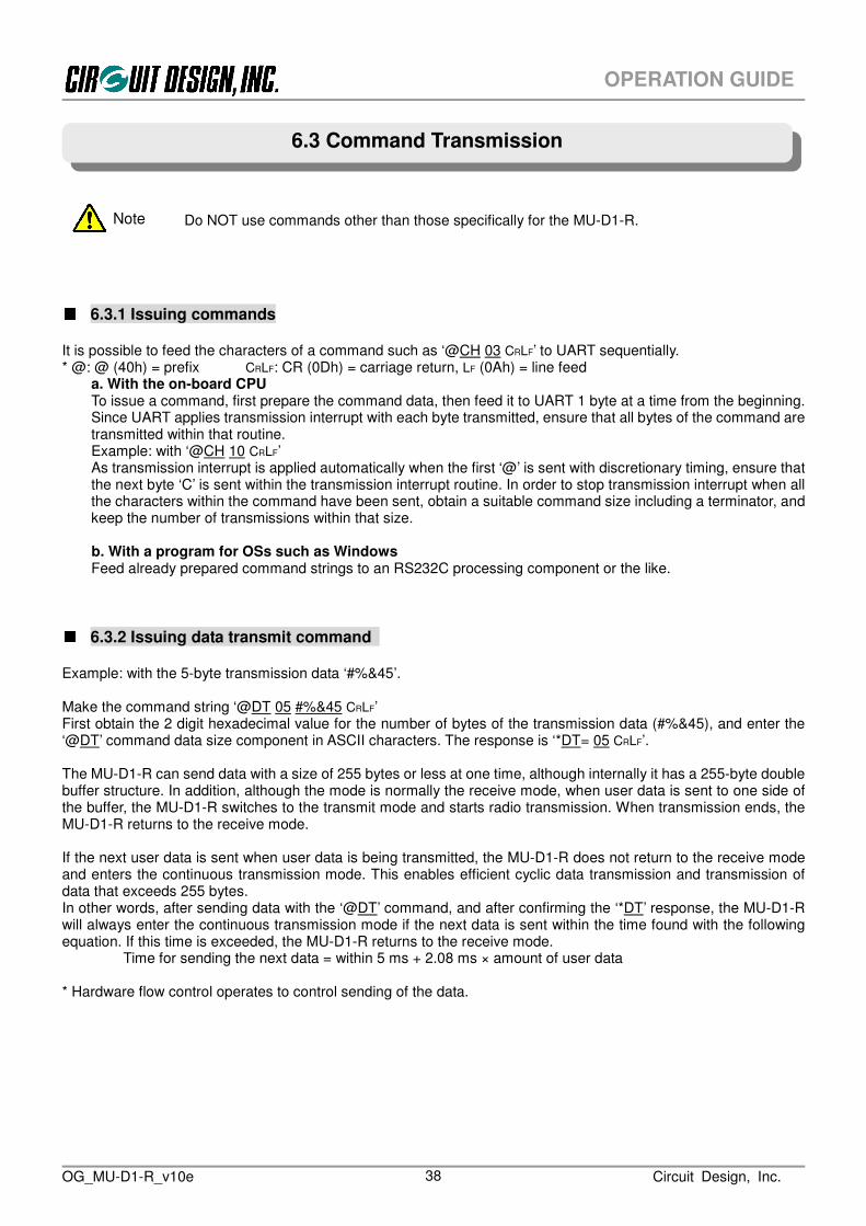
6.3.1 Issuing commands It is possible to feed the characters of a command such as ‘@CH 03 CRLF’ to UART sequentially. * @: @ (40h) = prefix CRLF: CR (0Dh) = carriage return, LF (0Ah) = line feed
a. With the on-board CPU To issue a command, first prepare the command data, then feed it to UART 1 byte at a time from the beginning. Since UART applies transmission interrupt with each byte transmitted, ensure that all bytes of the command are transmitted within that routine. Example: with ‘@CH 10 CRLF’ As transmission interrupt is applied automatically when the first ‘@’ is sent with discretionary timing, ensure that the next byte ‘C’ is sent within the transmission interrupt routine. In order to stop transmission interrupt when all the characters within the command have been sent, obtain a suitable command size including a terminator, and keep the number of transmissions within that size.
b. With a program for OSs such as Windows Feed already prepared command strings to an RS232C processing component or the like.
6.3.2 Issuing data transmit command
Example: with the 5-byte transmission data ‘#%&45’. Make the command string ‘@DT 05 #%&45 CRLF’ First obtain the 2 digit hexadecimal value for the number of bytes of the transmission data (#%&45), and enter the ‘@DT’ command data size component in ASCII characters. The response is ‘*DT= 05 CRLF’. The MU-D1-R can send data with a size of 255 bytes or less at one time, although internally it has a 255-byte double buffer structure. In addition, although the mode is normally the receive mode, when user data is sent to one side of the buffer, the MU-D1-R switches to the transmit mode and starts radio transmission. When transmission ends, the MU-D1-R returns to the receive mode.
If the next user data is sent when user data is being transmitted, the MU-D1-R does not return to the receive mode and enters the continuous transmission mode. This enables efficient cyclic data transmission and transmission of data that exceeds 255 bytes. In other words, after sending data with the ‘@DT’ command, and after confirming the ‘*DT’ response, the MU-D1-R will always enter the continuous transmission mode if the next data is sent within the time found with the following equation. If this time is exceeded, the MU-D1-R returns to the receive mode.
Time for sending the next data = within 5 ms + 2.08 ms × amount of user data * Hardware flow control operates to control sending of the data.
6.3 Command Transmission
Note

OG_MU-D1-R_v10e Circuit Design, Inc. 39
OPERATION GUIDE
6.3.3 Issuing commands continuously You cannot issue commands successively as in ‘@CH03CRLF@EI33CRLF@DI05CRLF’. In other words, there is always one response corresponding to one command, and the next command should not be issued until this response has been confirmed. The procedure is as follows. 1. Issue the command ‘@EI 33 CRLF’. Confirm (process) the response ‘*EI = 33 CRLF’ 2. Issue the command ‘@CH 03 CRLF’. Confirm (process) the response ‘*CH = 03 CRLF’ 3. Issue the command ‘@DI 05 CRLF’. Confirm (process) the response ‘*DI = 05 CRLF’
@DI05 + CRLF@CH03 + CRLF
Preparation
1. Create a transmit command string:Example @EI33 + CRLF@CH03 + CRLF@DI05 + CRLF2. Set the number of the command string
3. Enable issuing of the command
YesNoYesNo
Check the response to the previous commandand set the flag
Command strings tra
nsmitted in
order
Are there any remainingcommand strings ?
Can a commandbe issued ?
@EI33 + CRLF
6.3.4 Issuing commands continuously (when ignoring the response)
As shown in the timing diagram in Chapter 7, a response is returned for each command after a certain period of time has elapsed. It is possible to issue commands continuously by ignoring the responses and inserting a wait routine between each command. When using this method, allow plenty of extra time, and test the system thoroughly before commercializing the product.

OG_MU-D1-R_v10e Circuit Design, Inc. 40
OPERATION GUIDE
6.4.1 Responses and receives Responses and receives are returned by the MU-D1-R in the following cases.
1. When a command is issued (command response, error response) 2. Processing result from the target station corresponding to the issued command (receive reponse) 3. When data from the source station is received (data receive)
6.4.2 Response and receive formats All responses and receives start with the prefix ‘*’, and the command response name is the same 2 ASCII characters as the corresponding command. The ‘*DR’ receive indicates the transmitted data, and they correspond to the transmitting end ‘@DT’ command. After the 2 character response or receive name comes ‘=’, followed by bytes that indicate a parameter, value or data. At the end of the response and the receive, the 2 character terminator CRLF (0Dh, 0Ah) is appended.
Example: *CH = 1B CRLF *EI = 30 CRLF *DR = 0B 66666666666 CRLF
6.4.3 Response and receive types Responses and receives consist of the following types, and each type must be processed separately.
1. 2 character response: The response parameter is a 2 character response BR, CH, CP, CT, DI, DT, EI, ER, GI, IZ, MD, RA, PB, RM, SB, SR, TB, TC, VR Example: Command ‘@CH 1A CRLF’ Response: ‘*CH = 1A CRLF’
The value ‘1A’ consists of 2 ASCII characters that express a hexadecimal number. 2. 4 character response: The response parameter is a 4 character response
UI Example: Command ‘@UI 800F,xxxx CRLF’ Response: ‘*UI = 800F CRLF’
The value ‘800F’ consists of 4 ASCII characters that express a hexadecimal number.
3. 5 character response: The response parameter is a 2 character x 2 response RA Example: Command ‘@RA CRLF’ Response: ‘*RA = 65,6C CRLF’
The value ‘65’ ‘6C’ consists of 2 ASCII characters that express a hexadecimal number.
4. Data receive: Data when data is received by wireless Example: When wireless reception data with a 10 (0Ah) value is received.
Data receive ‘*DR = 0A 5555555555 CRLF’ The value ‘0A’ consists of 2 ASCII characters that express a hexadecimal number. After the data size comes the corresponding number of bytes of user data.
5. Number of channels × 2 antennas x 2 character response: 20 ch x 2 x 2 character response
RC 6. 9 character response: The response parameter is a 9 character response
SN 7. Items for which the response length cannot be regulated
The response length for VR cannot be regulated. These should be determined by their terminator.
6.4 Response and Receive Processing

OG_MU-D1-R_v10e Circuit Design, Inc. 41
OPERATION GUIDE
6.4.4 Response and receive processing First, the response and receive data that enters UART from the MU-D1-R is received by the ring buffer. If there is data in the ring buffer, the response and receive identification routine takes 1 byte at a time and performs interpretation of the response and the receive. After, the processing routines diverge in accordance with each response or receive. To determine the response and receive type, prepare a table of all responses and receives, and make a comparative judgement. It is convenient to return the result of comparison as an integer of the response or receive position on the table, and for the value to diverge to the processing routine. Arrange the responses and receives in the table divided into groups by type. Example:
array [‘BR’, ‘CH’, ‘CT’, ‘DI’, ‘DR’, ‘DT’, ‘EI’, ‘ER’, ‘GI’, ‘MD’, ‘PB’, ‘RA’, ‘RM’, ‘SB’, ‘TC’, ‘TB’, ‘UI’, ‘VR’] Response and receive values are ASCII strings that express a numerical value, so when using values, provide a routine to convert the ASCII characters into numerical values. For example, when data is received, the ‘*DR’ data receive value indicates the amount of user data received, so this is converted to a numerical value and only that amount of data is obtained.

OG_MU-D1-R_v10e Circuit Design, Inc. 42
OPERATION GUIDE

OG_MU-D1-R_v10e Circuit Design, Inc. 43
OPERATION GUIDE
With applications that use the MU-D1-R, in the development stage or when development is complete and the unit is actually used, it is necessary to assess the field status of the system at all times for stable communication. In other words, in the development stage when the MU-D1-R is mounted on the circuit board, it is necessary to consider the pattern design and arrangement of components to extract the optimum values for radio performance, and to ensure stable and reliable communication in operation, it is necessary to measure the state of the radio waves and the surrounding floor noise and to locate the equipment at the optimal point. The MU-D1-R has the following commands to allow convenient assessment of these aspects of communication. 1. @RA : Acquisition of the RSSI absolute level of the source station 2. @CP : Packet test
6.5.1 Source station RSSI measurement By issuing the @RA command, the RSSI level of the source station can be measured. It is possible to achieve optimization while measuring the high frequency noise from the unit itself and from peripheral equipment, and the signal level from the source station. To measure the signal level from the target station, it is possible to issue a command requesting continuous issue of data ‘@CT xx’ at the target station.
6.5.2 Packet test When transmitting data packets with the ‘@CP’ command, the data packet is returned from the target station wtihout change. Using this, it is possible to measure the packet success rate corresponding to the field status. A data size between 0 to 255 bytes can be set for each packet with the ‘@CP’ command. In order to locate the equipment in the optimum place, send packets repeatedly with the ‘@CP’ command and measure the packet success rate. Note, however, that the packet transmission procedures and the calculation of success rate must be programmed.
6.5 Assessing the Field Status for Communication
Command requesting the targetstation to issue continuous test data
@DT05@CT03/C
Sourcestation
Targetstation
RSSI absolute levelvalue acquisition
command@RA
Fieldnoise
Continuoustest data
Issue test datafor specified time
This and otherlocal equipment
@RA: Acquire source station RSSI
Data packet transmission(1...255byte)
Sourcestation
Targetstation
Packet testcommand
@CP
Return the received datawithout change@CP: Packet test

OG_MU-D1-R_v10e Circuit Design, Inc. 44
OPERATION GUIDE
The MU-D1-R can send data of 255 bytes or less at one time. When transmitting data in excess of 255 bytes, you will need to incorporate a transmission protocol so that, for example, data is split for transmisson. When transmitting and receiving user data frames, the MU-D1-R outputs only frames that are received correctly, and discards those frames that experience errors. There is no response issued for dropped frames. When transmitting large volumes of data such as files, it is performed using two-way communication such as ARQ (Automatic Repeat Request), and it is necessary to provide measures against dropped frames caused by wireless errors. Data frames include frame numbers and the like, and these are used as the criteria for ARQ.
6.6 Achieving Data Transmission

OG_MU-D1-R_v10e Circuit Design, Inc. 45
OPERATION GUIDE
The binary mode of the MU-D1-R is intended to be used for test communication. Applications that use the MU-D1-R should basically use the command mode. However, it is possible to develop simple applications using the binary mode for applications that send less than 255 bytes at a time, if certain conditions are met. This applies only to newly developed applications and does not mean that data output by existing equipment can be sent as is. In other words, the format, timing, and control lines for output data of existing equipment must match the content of this operation guide.
6.7.1 Modes
First, we will explain about the command mode and binary mode. The diagram below is a relational diagram of the MU-D1-R modes.
Mode terminal level High
Low Low@MDTX
MOD terminalLow@MDCD
MOD terminalLow@MDBI
MOD terminal
MOD terminal
HighMOD terminal
HighMOD terminal
HighCommand modeBinary mode Text mode
Command mode@MDTX@MDBI1, Reset (RST terminal) *12, Initialize (INI terminal) *2*1: When the mode is set in the RAM *2: When the mode is fixed in the EEPROM
Mode RegisterBI CD TX1, Issue the ESC code2, Reset (RST terminal) *13, Initialize (INI terminal) *2
BI: binary mode, CD: command mode, TX: text mode Command mode There are two ways to set the MU-D1-R to the command mode, as follows.
1. If the MODE terminal is set to H, the MU-D1-R is set to the command mode irrespective of the setting in the MU-D1-R mode register. 2. If the MODE terminal is set to L, when the power is turned on the MU-D1-R starts in the default mode set in the EEPROM. Depending on the mode, take the following action.
In the binary mode: Initialize the MU-D1-R. In the text mode: Issue the escape code: ‘ESC’.
* Initialization method: Set the INI terminal to Low and turn on the power. After turning off the power briefly, open the INI terminal and turn on the power again.
Binary mode There are two ways to set the MU-D1-R to the binary mode, as follows.
1. If the MODE terminal is set to H, set the MU-D1-R mode register to the binary mode with the ‘@MD BI’ command. Then set the MODE terminal to the L level. 2. If the MODE terminal is set to L, when the power is turned on the MU-D1-R starts in the default mode set in the EEPROM. Depending on the mode, take the following action. In the command mode: Set the MU-D1-R mode register to the binary mode with the ‘@MD BI’ command. In the text mode: Issue the escape code: ‘ESC’ and after setting the MU-D1-R to the command mode, switch modes.
6.7 Operation in Binary Mode

OG_MU-D1-R_v10e Circuit Design, Inc. 46
OPERATION GUIDE
6.7.2 When developing a new system
The binary mode of the MU-D1-R can be used in accordance with the following methods, however when it is used in this mode, it must meet the “Conditions for use of the binary mode”, explained later. Set the MODE terminal to be controlled by the CPU.
1. Using the binary mode while switching between the binary mode and command mode With applications that must change channels and the destination of transmissions, switch between the command mode and binary mode, using the CPU to control the MODE terminal. 2. Using only the binary mode directly after turning on the power If you want to use the MU-D1-R in the binary mode directly after turning on the power of the system, without changing channels or the destination of transmissions, issue the command “@MD BI /W” to set the MU-D1-R mode register and to fix the mode in the EEPROM. This setting is made only once at the beginning when first using the system. In addition, when turning on the power, set the MODE terminal to L. Use the command ‘/W’ option to fix the channel, User ID, Destination ID and so on in the EEPROM. 3. Connection example These are examples of connections in which hardware flow control is used and not used. Normally with the MU-D1-R, in order to prevent buffer overflow of the data buffer, hardware flow control is fixed as the flow control for serial communication. This also applies to the binary mode. However, if the data to send at one time is less than 255 bytes, data can be sent without performing flow control. In addition, since the various setting commands of the MU-D1-R are only a few bytes, there is no particular need for a flow control line. When using hardware flow control Set the UART of the control CPU to be controlled by hardware flow control.
RXDTXDCTS(Port)RTS(Port)Port User CPUwith UARTAntennaAAntennaB
MU-D1-R
TXD 1RXD 2RTS 3CTS 4MOD 5INI 6RST 7NC 89 NC10 RXB11 TXL12 RXA13 VCC14 GNDAAAABBBB
When not using hardware flow control 1. Set the CTS terminal to L level, and open the RTS terminal. 2. Set the UART of the control CPU to no flow control.
RXDTXD User CPUwith UARTAntennaB AntennaA
MU-D1-R
TXD 1RXD 2RTS 3CTS 4MOD 5INI 6RST 7NC 89 NC10 RXB11 TXL12 RXA13 VCC14 GNDAAAABBBB

OG_MU-D1-R_v10e Circuit Design, Inc. 47
OPERATION GUIDE
6.7.3 When using only the data line of existing equipment
Caution is necessary when using the MU-D1-R connected to existing RS232C equipment. Although RS232C has regulations for its own data format, use of the control line differs depending on the equipment. Equipment that was previously connected with a cable cannot just be connected with the MU-D1-R. Essentially, the status of the control line can be ignored with only the data line connected, however the data transmission timing and data format of the existing equipment can only be used if it meets the “Conditions for use of the binary mode”, explained later. To check whether these conditions are met, first carry out an investigation using an oscilloscope or the like. Example of connection Since the output from existing equipment is normally RS232C, in order to connect to the MU-D1-R, convert the output level with a RS232C transceiver IC. In addition, consider means of enabling the various settings to be made in the command mode. For example, the following procedure can be used. 1. Provide your circuit board with a socket, and mount the MU-D1-R after performing the various settings using a
dedicated board. 2. Set the MODE terminal of the MU-D1-R to L or H with the switch, to switch between the command mode and
binary mode . *Since the various setting commands of the MU-D1-R are only a few bytes, there is no particular need for a flow control line.
RXDTXDOpen = Command mode EquipmentRS232TransceiverAntennaAAntennaBMU-D1-R
TXD 1RXD 2RTS 3CTS 4MOD 5INI 6RST 7NC 89 NC10 RXB11 TXL12 RXA13 VCC14 GNDAAAABBBB
* The MODE terminal is pulled up internally.
6.7.4 Conditions for use of the binary mode
1. Make the size of data sent at one time less than 255 bytes. 2. Data transmission should be timed so that radio transmission of the previously transmitted data is finished
completely.
Timing of data transmission The transmission speed of radio transmission is 600 kbps (40 kbps x 15 chips), so find the correct timing with the following formula. Data transmission timing = 18 ms + 0.2 ms × amount of user data + time without input in the binary mode
The start of radio transmission of data follows immediately after the time set with the time without input in the binary mode setting command (‘@TB’) has elapsed.
3. The internal operation of the MU-D1-R is unreliable for 100 ms after the power is turned on, so data should
not be sent during this interval. 4. During input or when data is being sent to the MU-D1-R, do not switch the MODE terminal

OG_MU-D1-R_v10e Circuit Design, Inc. 48
OPERATION GUIDE
tC = A×10000/br tR = B×10000/br
General command & command response timing
(excluding the @CH, @RA, @BR commands)0.1msIssue commandResponse tC tR
A = Command length
A=5 : VR,SN,SR,IZ,RA
A=7 : GI,EI,DI,CH,PB,SB,MD,TC,TB,CT,RI,RM,SI
A=14 : UI
B = Response length
B=8 : GI,EI,DI,CH,BR,PB,SB,MD,TC,TB,CT,RI,RM,SR,IZ,SI
B=10 : UI
B=11 : RA
B=15 : SN
* Units are ms Br = UART bit rate
Commands can be issuedPower ON(Power supply VCC)MU-D1-R operation 100ms
Period when issuing commands is prohibited when
turning on power
Period when commands is prohibited
Chapter 7 Timing

OG_MU-D1-R_v10e Circuit Design, Inc. 49
OPERATION GUIDE
CH command & command response timing5msIssue the @CH command*CH response @CH *CHRA, command & command response timing23msIssue the @RA command*RA response @RA *RA
Command & command response timing
when /w option is specified 65msIssue command with /wResponse * 60ms when @CH/w (written in the EEPROM)
BR command & command response timing1msIssue the @BR command*BR response @BR *BR Commands can be issuedMU-D1-R operation 200msPeriod when commands is prohibited

OG_MU-D1-R_v10e Circuit Design, Inc. 50
OPERATION GUIDE
Time to establish link (when 1 frame is transmitted)
@DT *DR *DRSource stationData transmit command@DTTarget stationData receive &Data transmit commandSource stationData receive*DR
* Units are ms, n = number of data bytes sent (within 255 bytes), bR = UART bit date
tC tP tPtUser tR*DT : Data transmit response *DR : data receive
@DTtR tCtUser = User program processing time
tLink
tLink = Time to establish link
Command time tC = (n + 7) x 10000 / br Radio transmission time tP = (n + 0.2) + 15ms
Data receive time tR = (n + 8) x 10000 / br
Data transmit command time
Data transmit response time tR = 8 x 10000 / br
Data transmit command time tC = N x 10000 / br
Source stationData transmit command@DTData transmit response*DT@DT *DT150μstC tR
* Units are ms, br = UART bit rate, N = n + 7n = Number of data bytes sent (within 255bytes)

OG_MU-D1-R_v010e Circuit Design, Inc. 51
OPERATION GUIDE
We recommend that you use the dedicated MU-2-R Evaluation
You can perform a simple operational check using the Windows accessory HyperTerminal. The following is an explanation of how to use HyperTerminal, and cautions when using the program. Please read the detailed explanation of the commands before starting the evaluation. When performing evaluation using a computer, mount the MU-D1-R on a RS232C conversion board.
Preparation Before starting the evaluation, turn on the power while pressing the RESET button of the RS232C conversion board, and turn on the power again to initialize the content of the EEPROM (non-volatile memory) inside the MU-D1-R. The initial values of the parameters are as follows.
Initial values for link related parameters User ID = 0000h Group ID = 00h Equipment ID = 01h Destination ID = 01 Channel to use CH = Lowest channel number
Initial values for RS232C related parameters Baud rate: 19,200 bps, Data bits: 8 bits, Parity: none, Stop bit: 1, Flow control: RTS, CTS hardware control
* Initialization using the RESET SW initializes all of the MU-D1-R parameters, so do not press it for any other reason than initialization.
Evaluation Start up HyperTerminal, then set the communication parameters using the example at right for reference. Refer to the Cautions for important information. Issue the various commands from the keyboard. Refer to the section on modes for evaluating the different modes.
Settings
Note 1. ‘CRLF’ in the detailed explanation of commands means the “Enter” key on the computer keyboard. When testing the commands with HyperTerminal or the like, press the “Enter” key for CRLF. However, the “Enter” key on the number keypad outputs ‘CR’ in HyperTerminal, so it should not be used.
2. With HyperTerminal, pressing a key outputs the corresponding code, so the “Backspace” key and “Delete” key should not be pressed. 3. With HyperTerminal, the DTR line is always fixed at High Level and cannot be controlled.
Chapter 8 Evaluation Uing Hyper Terminal
8.1 Method of Evaluation Using HyperTerminal

OG_MU-D1-R_v010e Circuit Design, Inc. 52
USA-Federal Communications Commission (FCC) The MU-D1-R complies with Part 15 of the FCC Rules. Operation is subject to the following two conditions: (1) This device may not cause harmful interference, and (2) This device must accept any interference received, including interference that may cause undesired operation. Caution Any changes or modifications not expressly approved by the party responsible for compliance could void the user’s authority to operate the equipment. Labeling Circuit Design RF module MU-D1-R labeled as below.
FCC ID: V9X-MUD1R The proposed with FCC ID label format is to be placed on the module. If FCC ID is not visible when the module is installed into the system, “Contains FCC ID: V9X-MUD1R ” shall be placed on the outside of final host system. Caution: Exposure to Radio Frequency Radiation. To comply with FCC RF exposure compliance requirements, a separation distance of at least 20 cm must be maintained between the antenna of this device and all persons. This device must not be co-located or operating in conjunction with any other antenna or transmitter. This equipment has been tested and found to comply with the limits for a Class B digital device, pursuant to part 15 of the FCC Rules. These limits are designed to provide reasonable protection against harmful interference in a residential installation. This equipment generates, uses and can radiate radio frequency energy and, if not installed and used in accordance with the instructions, may cause harmful interference to radio communications. However, there is no guarantee that interference will not occur in a particular installation. If this equipment does cause harmful interference to radio or television reception, which can be determined by turning the equipment off and on, the user is encouraged to try to correct the interference by one or more of the following measures: - Reorient or relocate the receiving antenna. - Increase the separation between the equipment and receiver. - Connect the equipment into and outlet on a circuit different from that to which the receiver is connected. - Consult the dealer or an experienced radio/TX technician for help.
Chapter 9 Regulatory Compliance
9.1 Regulatory Compliance of the MU-D1-R

OG_MU-D1-R_v010e Circuit Design, Inc. 53
Important notice • Customers are advised to consult with Circuit Design sales representatives before ordering.
Circuit Design believes the provided information is accurate and reliable. However, Circuit Design reserves the
right to make changes to this product without notice.
• Circuit Design products are neither designed nor intended for use in life support applications where malfunction can reasonably be expected to result in significant personal injury to the user. Any use of Circuit Design products in such safety-critical applications is understood to be fully at the risk of the customer and the customer must fully indemnify Circuit Design, Inc for any damages resulting from any improper use.
• As the radio module communicates using electronic radio waves, there are cases where transmission will be temporarily cut off due to the surrounding environment and method of usage. The manufacturer is exempt from all responsibility relating to resulting harm to personnel or equipment and other secondary damage.
• The manufacturer is exempt from all responsibility relating to secondary damage resulting from the operation, performance and reliability of equipment connected to the radio module.
Copyright
• All rights in this operation guide are owned by Circuit Design, Inc. No part of this document may be copied or
distributed in part or in whole without the prior written consent of Circuit Design, Inc.
Cautions • Do not use the equipment within the vicinity of devices that may malfunction as a result of electronic radio waves
from the radio module. • Communication performance will be affected by the surrounding environment, so communication tests should be
carried out before actual use. • Ensure that the power supply for the radio module is within the specified rating. Short circuits and reverse
connections may result in overheating and damage and must be avoided at all costs. • Ensure that the power supply has been switched off before attempting any wiring work. • The case is connected to the GND terminal of the internal circuit, so do not make contact between the '+' side of
the power supply terminal and the case. • When batteries are used as the power source, avoid short circuits, recharging, dismantling, and pressure. Failure
to observe this caution may result in the outbreak of fire, overheating and damage to the equipment. Remove the batteries when the equipment is not to be used for a long period of time. Failure to observe this caution may result in battery leaks and damage to the equipment.
• Do not use this equipment in vehicles with the windows closed, in locations where it is subject to direct sunlight, or in locations with extremely high humidity.
• The radio module is neither waterproof nor splash proof. Ensure that it is not splashed with soot or water. Do not use the equipment if water or other foreign matter has entered the case.
• Do not drop the radio module or otherwise subject it to strong shocks. • Do not subject the equipment to condensation (including moving it from cold locations to locations with a
significant increase in temperature.) • Do not use the equipment in locations where it is likely to be affected by acid, alkalis, organic agents or corrosive
gas. • Do not bend or break the antenna. Metallic objects placed in the vicinity of the antenna will have a great effect on
communication performance. As far as possible, ensure that the equipment is placed well away from metallic objects.
• The GND for the radio module will also affect communication performance. If possible, ensure that the case GND and the circuit GND are connected to a large GND pattern.
Warnings • Do not take a part or modify the equipment. • Do not remove the product label (the label attached to the upper surface of the module.) Using a module from
which the label has been removed is prohibited.
Copyright 2010, Circuit Design, Inc.
REVISION HISTORY

OG_MU-D1-R_v010e Circuit Design, Inc. 54
Version Date Description Remark 0.9 Aug. 2010 Preliminary 0.91 Oct. 2010 Preliminary Timing charts updated 1.0 Dec. 2010 Regulatory information, External view and Evaluation
method added.


![SummaryMap ward2 [Converted] · 2019-10-01 · MU-2 MU-6 MU-16 MU-14 MU-6 MU-2 MU-20 MU-9 MU-4 MU-13 MU-15 MU-13 MU-16 MU-18 MU-22 MU-19 MU-16 MU-27 MU-4 MU-3A MU-17 MU-13 MU-4](https://img.pdfslide.us/doc/110x75/5f5e4f591750d150e9633369/summarymap-ward2-converted-2019-10-01-mu-2-mu-6-mu-16-mu-14-mu-6-mu-2-mu-20.jpg)