Embed Size (px)
Citation preview

MTM5400TETRA Mobile TerminalInstallation Manual
When printed by Motorola
Publication Number68015000181-B
@68015000181@


COPYRIGHT MTM5400 Mobile Terminal Installation Manual 3
COPYRIGHT
Copyrights
© 2010 by Motorola Inc. All rights reserved.
No part of this manual may be reproduced, transmitted, stored in a retrieval system, or translated into any language or computer language, in any form or by any means, without the prior written permission of Motorola Inc.
Computer Software Copyrights
The Motorola products described in this manual may include copyrighted Motorola computer programs stored in semiconductor memories or other media. Laws in the United States and other countries preserve for Motorola certain exclusive rights for copyrighted computer programs including, but not limited to, the exclusive right to copy or reproduce in any form the copyrighted computer program. Accordingly, any copyrighted Motorola computer programs contained in the Motorola products described in this manual may not be copied, reproduced, modified, reverse-engineered, or distributed in any manner without the express written permission of Motorola. Furthermore, the purchase of Motorola products shall not be deemed to grant either directly or by implication, estoppel, or otherwise, any license under the copyrights, patents or patent applications of Motorola, except for the normal non-exclusive royalty-free license to use that arises by operation of law in the sale of a product.
Trademarks
Motorola, the Motorola Logo and all other trademarks identified as such herein are trademarks of Motorola Inc. All other product or service names are the property of their respective owners.

4 MTM5400 Mobile Terminal Installation Manual
THIS PAGE INTENTIONALLY LEFT BLANK
Product Safety and RF Exposure MTM5400 Mobile Terminal Installation Manual 5
IMPORTANT SAFETY INFORMATION
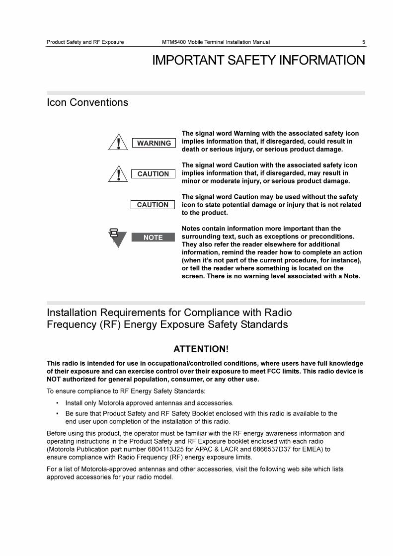
Icon Conventions
Installation Requirements for Compliance with Radio Frequency (RF) Energy Exposure Safety Standards
ATTENTION!
This radio is intended for use in occupational/controlled conditions, where users have full knowledge
of their exposure and can exercise control over their exposure to meet FCC limits. This radio device is
NOT authorized for general population, consumer, or any other use.
To ensure compliance to RF Energy Safety Standards:
• Install only Motorola approved antennas and accessories.
• Be sure that Product Safety and RF Safety Booklet enclosed with this radio is available to the
end user upon completion of the installation of this radio.
Before using this product, the operator must be familiar with the RF energy awareness information and
operating instructions in the Product Safety and RF Exposure booklet enclosed with each radio
(Motorola Publication part number 6804113J25 for APAC & LACR and 6866537D37 for EMEA) to
ensure compliance with Radio Frequency (RF) energy exposure limits.
For a list of Motorola-approved antennas and other accessories, visit the following web site which lists
approved accessories for your radio model.
The signal word Warning with the associated safety icon
implies information that, if disregarded, could result in
death or serious injury, or serious product damage.
The signal word Caution with the associated safety icon
implies information that, if disregarded, may result in
minor or moderate injury, or serious product damage.
The signal word Caution may be used without the safety
icon to state potential damage or injury that is not related
to the product.
Notes contain information more important than the
surrounding text, such as exceptions or preconditions.
They also refer the reader elsewhere for additional
information, remind the reader how to complete an action
(when it’s not part of the current procedure, for instance),
or tell the reader where something is located on the
screen. There is no warning level associated with a Note.
6 MTM5400 Mobile Terminal Installation Manual Product Safety and RF Exposure
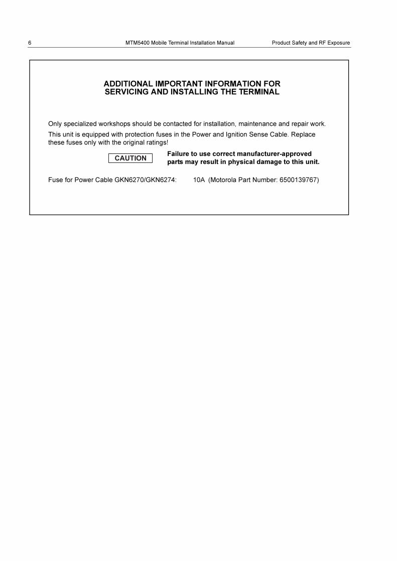
Only specialized workshops should be contacted for installation, maintenance and repair work.
This unit is equipped with protection fuses in the Power and Ignition Sense Cable. Replace
these fuses only with the original ratings!
Fuse for Power Cable GKN6270/GKN6274: 10A (Motorola Part Number: 6500139767)
Failure to use correct manufacturer-approved
parts may result in physical damage to this unit.
ADDITIONAL IMPORTANT INFORMATION FOR SERVICING AND INSTALLING THE TERMINAL

DOCUMENT HISTORY MTM5400 Mobile Terminal Installation Manual 7
DOCUMENT HISTORY
The following major changes have been implemented in this manual since the previous edition:
Edition Description Date
68015000181-A Initial edition Dec 2010
68015000181-B Toroid updates Dec 2010

8 MTM5400 Mobile Terminal Installation Manual
THIS PAGE INTENTIONALLY LEFT BLANK
CONTENTS MTM5400 Mobile Terminal Installation Manual 9
CONTENTS
COPYRIGHT. . . . . . . . . . . . . . . . . . . . . . . . . . . . . . . . . . . . . . . . . . . . . . . . . . 3
Copyrights . . . . . . . . . . . . . . . . . . . . . . . . . . . . . . . . . . . . . . . . . . . . . . . . . . . . . . . . . 3
Computer Software Copyrights . . . . . . . . . . . . . . . . . . . . . . . . . . . . . . . . . . . . . . . . 3
Trademarks . . . . . . . . . . . . . . . . . . . . . . . . . . . . . . . . . . . . . . . . . . . . . . . . . . . . . . . . 3
IMPORTANT SAFETY INFORMATION . . . . . . . . . . . . . . . . . . . . . . . . . . . . . 5
Icon Conventions . . . . . . . . . . . . . . . . . . . . . . . . . . . . . . . . . . . . . . . . . . . . . . . . . . . 5
Installation Requirements for Compliance with Radio Frequency (RF) Energy Exposure Safety Standards . . . . . . . . . . . . . . . . . . . . . . . . . . . . . . . . . . . . . . . . . . . 5
Additional Important Information for Servicing and Installing the Terminal. . . . 6
DOCUMENT HISTORY. . . . . . . . . . . . . . . . . . . . . . . . . . . . . . . . . . . . . . . . . . 7
CONTENTS . . . . . . . . . . . . . . . . . . . . . . . . . . . . . . . . . . . . . . . . . . . . . . . . . . 9
SCOPE . . . . . . . . . . . . . . . . . . . . . . . . . . . . . . . . . . . . . . . . . . . . . . . . . . . . . 13
Scope of This Manual . . . . . . . . . . . . . . . . . . . . . . . . . . . . . . . . . . . . . . . . . . . . . . . 13
MTM5400 Manuals and User Guides. . . . . . . . . . . . . . . . . . . . . . . . . . . . . . . . . . . . . . . . 14
Warranty and Service Support. . . . . . . . . . . . . . . . . . . . . . . . . . . . . . . . . . . . . . . . . . . 15
Service Information . . . . . . . . . . . . . . . . . . . . . . . . . . . . . . . . . . . . . . . . . . . . . . . . 16
Europe, Middle East and Africa Region . . . . . . . . . . . . . . . . . . . . . . . . . . . . . . . . . . . . . . 16
EMEA Systems Support Centre (ESSC) . . . . . . . . . . . . . . . . . . . . . . . . . . . . . . . . . . . 16
EMEA Systems Component Centre (ESCC) . . . . . . . . . . . . . . . . . . . . . . . . . . . . . . . . 16
Parts Identification and Ordering . . . . . . . . . . . . . . . . . . . . . . . . . . . . . . . . . . . . . . . . . 17
EMEA Test Equipment Support. . . . . . . . . . . . . . . . . . . . . . . . . . . . . . . . . . . . . . . . . . 17
Your Input . . . . . . . . . . . . . . . . . . . . . . . . . . . . . . . . . . . . . . . . . . . . . . . . . . . . . . . . . . 17
Updated Versions of this Manual. . . . . . . . . . . . . . . . . . . . . . . . . . . . . . . . . . . . . . . . . 17
Asia, Pacific Region . . . . . . . . . . . . . . . . . . . . . . . . . . . . . . . . . . . . . . . . . . . . . . . . . . . . . 18
Piece Parts . . . . . . . . . . . . . . . . . . . . . . . . . . . . . . . . . . . . . . . . . . . . . . . . . . . . . . . . . 18
Technical Support . . . . . . . . . . . . . . . . . . . . . . . . . . . . . . . . . . . . . . . . . . . . . . . . . . . . 18
Further Assistance from Motorola . . . . . . . . . . . . . . . . . . . . . . . . . . . . . . . . . . . . . . . . 18
Parts Identification and Ordering . . . . . . . . . . . . . . . . . . . . . . . . . . . . . . . . . . . . . . . . . 18
Latin America Region . . . . . . . . . . . . . . . . . . . . . . . . . . . . . . . . . . . . . . . . . . . . . . . . . . . . 19
MODEL INFORMATION & ACCESSORIES . . . . . . . . . . . . . . . . . . . . . . . . 21
MTM5400 Mobile Terminal Model Information . . . . . . . . . . . . . . . . . . . . . . . . . . . 21
Sales Model Nomenclature . . . . . . . . . . . . . . . . . . . . . . . . . . . . . . . . . . . . . . . . . . 21
10 MTM5400 Mobile Terminal Installation Manual CONTENTS
Model Specifications* . . . . . . . . . . . . . . . . . . . . . . . . . . . . . . . . . . . . . . . . . . . . . . . . . . . . 22
Model Descriptions** . . . . . . . . . . . . . . . . . . . . . . . . . . . . . . . . . . . . . . . . . . . . . . . . . . . . . 22
Accessories-to-Model Chart . . . . . . . . . . . . . . . . . . . . . . . . . . . . . . . . . . . . . . . . . . . . . . . 23
INSTALLATION . . . . . . . . . . . . . . . . . . . . . . . . . . . . . . . . . . . . . . . . . . . . . . 27
Introduction . . . . . . . . . . . . . . . . . . . . . . . . . . . . . . . . . . . . . . . . . . . . . . . . . . . . . . .27
General Information. . . . . . . . . . . . . . . . . . . . . . . . . . . . . . . . . . . . . . . . . . . . . . . . . . . . . . 27
DC Power Cable Installation. . . . . . . . . . . . . . . . . . . . . . . . . . . . . . . . . . . . . . . . . .28
Installation Planning. . . . . . . . . . . . . . . . . . . . . . . . . . . . . . . . . . . . . . . . . . . . . . . . . . . . . . 28
Installation Procedure . . . . . . . . . . . . . . . . . . . . . . . . . . . . . . . . . . . . . . . . . . . . . . . . . . . . 29
Terminal Installation . . . . . . . . . . . . . . . . . . . . . . . . . . . . . . . . . . . . . . . . . . . . . . . .31
Enhanced Control Head Installation . . . . . . . . . . . . . . . . . . . . . . . . . . . . . . . . . . . . . . . . . 31
Trunnion Installation . . . . . . . . . . . . . . . . . . . . . . . . . . . . . . . . . . . . . . . . . . . . . . . . . . . . . 32
Installation Planning . . . . . . . . . . . . . . . . . . . . . . . . . . . . . . . . . . . . . . . . . . . . . . . . . . . 32
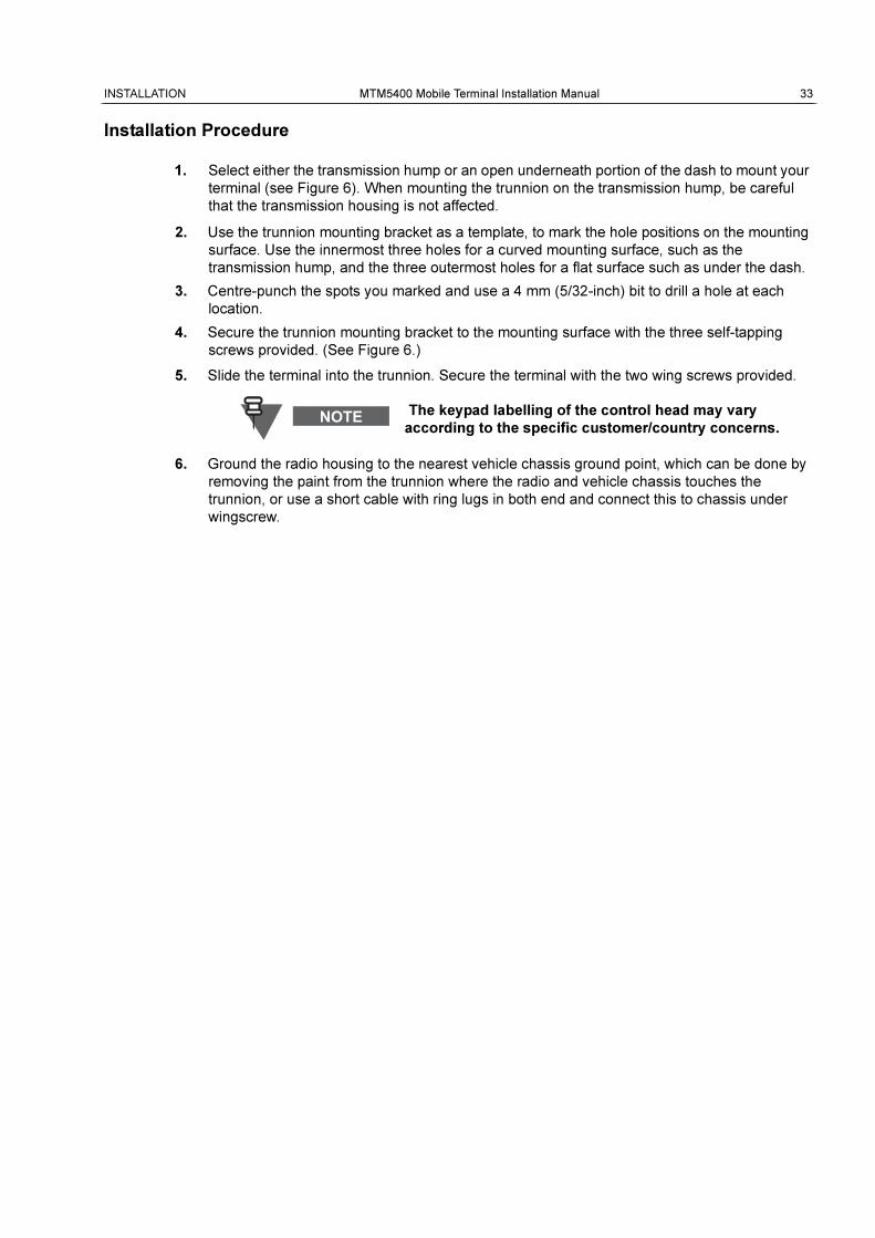
Installation Procedure . . . . . . . . . . . . . . . . . . . . . . . . . . . . . . . . . . . . . . . . . . . . . . . . . . 33
Dashboard Installation . . . . . . . . . . . . . . . . . . . . . . . . . . . . . . . . . . . . . . . . . . . . . . . . . . . . 34
Installing the Radio in an Automotive Dashboard . . . . . . . . . . . . . . . . . . . . . . . . . . . . . 34
Mounting the Radio in the Frame . . . . . . . . . . . . . . . . . . . . . . . . . . . . . . . . . . . . . . . . . 35
Remove the Radio from the Frame. . . . . . . . . . . . . . . . . . . . . . . . . . . . . . . . . . . . . . . . 37
Desktop Installation . . . . . . . . . . . . . . . . . . . . . . . . . . . . . . . . . . . . . . . . . . . . . . . . . . . . . . 38
Planning . . . . . . . . . . . . . . . . . . . . . . . . . . . . . . . . . . . . . . . . . . . . . . . . . . . . . . . . . . . . 38
Installation. . . . . . . . . . . . . . . . . . . . . . . . . . . . . . . . . . . . . . . . . . . . . . . . . . . . . . . . . . . 38
Remote Mount Installation. . . . . . . . . . . . . . . . . . . . . . . . . . . . . . . . . . . . . . . . . . . . . . . . . 40
Installing the Remote Mount Enhanced Control Head onto the Remote Mount Trunnion
41
Installing the Remote Mount Enhanced Control Head in a DIN Mount Bracket . . . . . . 42
Inserting the Remote Mount Enhanced Control Head with the DIN Mount Bracket into the
DIN Frame . . . . . . . . . . . . . . . . . . . . . . . . . . . . . . . . . . . . . . . . . . . . . . . . . . . . . . . . . . 43
Adding Extra Connectivity to the Remote Head . . . . . . . . . . . . . . . . . . . . . . . . . . . . . . 44
Installing the Accessories Expansion Cable . . . . . . . . . . . . . . . . . . . . . . . . . . . . . . . . . 44
Motorcycle Mount Enhanced Control Head Installation. . . . . . . . . . . . . . . . . . . . . . . . . . . 45
Planning . . . . . . . . . . . . . . . . . . . . . . . . . . . . . . . . . . . . . . . . . . . . . . . . . . . . . . . . . . . . 45
Installing the Motorcycle Mount Enhanced Control Head . . . . . . . . . . . . . . . . . . . . . . . 46
Mechanical Parts . . . . . . . . . . . . . . . . . . . . . . . . . . . . . . . . . . . . . . . . . . . . . . . . . . . . . 48
Installation of the Motorcycle Mount TELCO Cable (PMKN4030) . . . . . . . . . . . . . . . . 48
Adding Extra Connectivity to the Motorcycle Mount Enhanced Control Head . . . . . . . 48
Data Expansion Head Enhanced Installation . . . . . . . . . . . . . . . . . . . . . . . . . . . .49
Data Expansion Head Enhanced Radio without Control Head . . . . . . . . . . . . . . . . . . . . . 49
Data Expansion Head Enhanced with 3rd Party Control Head . . . . . . . . . . . . . . . . . . . . . 50
Data Box Radio . . . . . . . . . . . . . . . . . . . . . . . . . . . . . . . . . . . . . . . . . . . . . . . . . . . . . . . . . 51
Junction Box Installation . . . . . . . . . . . . . . . . . . . . . . . . . . . . . . . . . . . . . . . . . . . . . . . . . . 52
General . . . . . . . . . . . . . . . . . . . . . . . . . . . . . . . . . . . . . . . . . . . . . . . . . . . . . . . . . . . . . 52
Installation. . . . . . . . . . . . . . . . . . . . . . . . . . . . . . . . . . . . . . . . . . . . . . . . . . . . . . . . . . . 52
Service . . . . . . . . . . . . . . . . . . . . . . . . . . . . . . . . . . . . . . . . . . . . . . . . . . . . . . . . . . . . . 53
Connections . . . . . . . . . . . . . . . . . . . . . . . . . . . . . . . . . . . . . . . . . . . . . . . . . . . . . . . . . 53

CONTENTS MTM5400 Mobile Terminal Installation Manual 11
Connection Plan for the Junction Box Accessory Terminal . . . . . . . . . . . . . . . . . . . . . 54
Connection Plan for Accessory Connector Kit (HLN9457) . . . . . . . . . . . . . . . . . . . . . 56
Connectors and Pin Assignment of the Radio. . . . . . . . . . . . . . . . . . . . . . . . . . . 58
Transceiver Rear Side - Pin Function. . . . . . . . . . . . . . . . . . . . . . . . . . . . . . . . . . . . . . . . 58
Accessory Connection Plan . . . . . . . . . . . . . . . . . . . . . . . . . . . . . . . . . . . . . . . . . . . . . . . 60
Re-crimp Procedure. . . . . . . . . . . . . . . . . . . . . . . . . . . . . . . . . . . . . . . . . . . . . . . . . . . 61
Connectors and Pin Assignment of Data Expansion Head Enhanced and Remote Head Enhanced. . . . . . . . . . . . . . . . . . . . . . . . . . . . . . . . . . . . . . . . . . . . . 62
10-Pin TELCO Connector . . . . . . . . . . . . . . . . . . . . . . . . . . . . . . . . . . . . . . . . . . . . . . 62
25-Pin subD Connector . . . . . . . . . . . . . . . . . . . . . . . . . . . . . . . . . . . . . . . . . . . . . . . . 63
9-Pin subD Connector . . . . . . . . . . . . . . . . . . . . . . . . . . . . . . . . . . . . . . . . . . . . . . . . . 64
Connector and Pin Assignment of the Enhanced Control Head . . . . . . . . . . . . 65
Connecting Cables . . . . . . . . . . . . . . . . . . . . . . . . . . . . . . . . . . . . . . . . . . . . . . . . . 68
Motorcycle Mount Enhanced Control Head-to-Remote Head Enhanced/Data Expansion
Head Enhanced (Motorcycle Mount TELCO Cable) . . . . . . . . . . . . . . . . . . . . . . . . . . . . 68
Remote Mount Enhanced Control Head/Motorcycle Mount Enhanced Control Head-to-
Accessories (Accessories Expansion Cable) . . . . . . . . . . . . . . . . . . . . . . . . . . . . . . . . . . 69
Radio-to-Junction Box . . . . . . . . . . . . . . . . . . . . . . . . . . . . . . . . . . . . . . . . . . . . . . . . . . . 71
Data Expansion Head Enhanced Radio-to-Data Device . . . . . . . . . . . . . . . . . . . . . . . . . 72
Data Expansion Head Enhanced Radio-to-Fist Microphone . . . . . . . . . . . . . . . . . . . . . . 73
Operation . . . . . . . . . . . . . . . . . . . . . . . . . . . . . . . . . . . . . . . . . . . . . . . . . . . . . . . . . . . 73
Making Connections . . . . . . . . . . . . . . . . . . . . . . . . . . . . . . . . . . . . . . . . . . . . . . . . . . 73
Removing the Existing Coiled Cord Cable. . . . . . . . . . . . . . . . . . . . . . . . . . . . . . . . . . 73
Radio-to-Data Device: Active Data Cable . . . . . . . . . . . . . . . . . . . . . . . . . . . . . . . . . . . . 75
Cable Connectivity . . . . . . . . . . . . . . . . . . . . . . . . . . . . . . . . . . . . . . . . . . . . . . . . . . . . 75
Vehicle Antenna Installation . . . . . . . . . . . . . . . . . . . . . . . . . . . . . . . . . . . . . . . . . 76
Mobile Radio Operation and EME Exposure . . . . . . . . . . . . . . . . . . . . . . . . . . . . . . . . . . 76
Selecting an Antenna Site . . . . . . . . . . . . . . . . . . . . . . . . . . . . . . . . . . . . . . . . . . . . . . . . 76
Antenna Installation Procedure . . . . . . . . . . . . . . . . . . . . . . . . . . . . . . . . . . . . . . . . . . . . 77
Completing the Installation . . . . . . . . . . . . . . . . . . . . . . . . . . . . . . . . . . . . . . . . . . . . . . . . 77
External Speaker Installation. . . . . . . . . . . . . . . . . . . . . . . . . . . . . . . . . . . . . . . . . 78
APPENDIX . . . . . . . . . . . . . . . . . . . . . . . . . . . . . . . . . . . . . . . . . . . . . . . . . . 79
Product Specific Information. . . . . . . . . . . . . . . . . . . . . . . . . . . . . . . . . . . . . . . . . 79
Equipment Electrical Ratings . . . . . . . . . . . . . . . . . . . . . . . . . . . . . . . . . . . . . . . . . . . . . . 79
Normal Load Conditions. . . . . . . . . . . . . . . . . . . . . . . . . . . . . . . . . . . . . . . . . . . . . . . . . . 79
Fuse Identification . . . . . . . . . . . . . . . . . . . . . . . . . . . . . . . . . . . . . . . . . . . . . . . . . . . . . . 80

12 MTM5400 Mobile Terminal Installation Manual
THIS PAGE INTENTIONALLY LEFT BLANK

SCOPE MTM5400 Mobile Terminal Installation Manual 13
SCOPE
Scope of This Manual
This manual is intended for use by service technicians familiar with similar types of equipment. It
contains information required for the installation of the equipment described and is current as of the
printing date. Changes which occur after printing date may be incorporated by a complete Manual
revision or alternatively as additions.
This manual is divided into the following sections:
• Safety and General Information
• Document History
• Contents
• Scope of this manual
• Model Information
• Installation
• APPENDIX Product Specific Information
The mobile terminal has to be installed by trained service
personnel only.
All installations should take place in accordance with the
requirements of the vehicle and antenna
manufacturer/supplier.
14 MTM5400 Mobile Terminal Installation Manual SCOPE
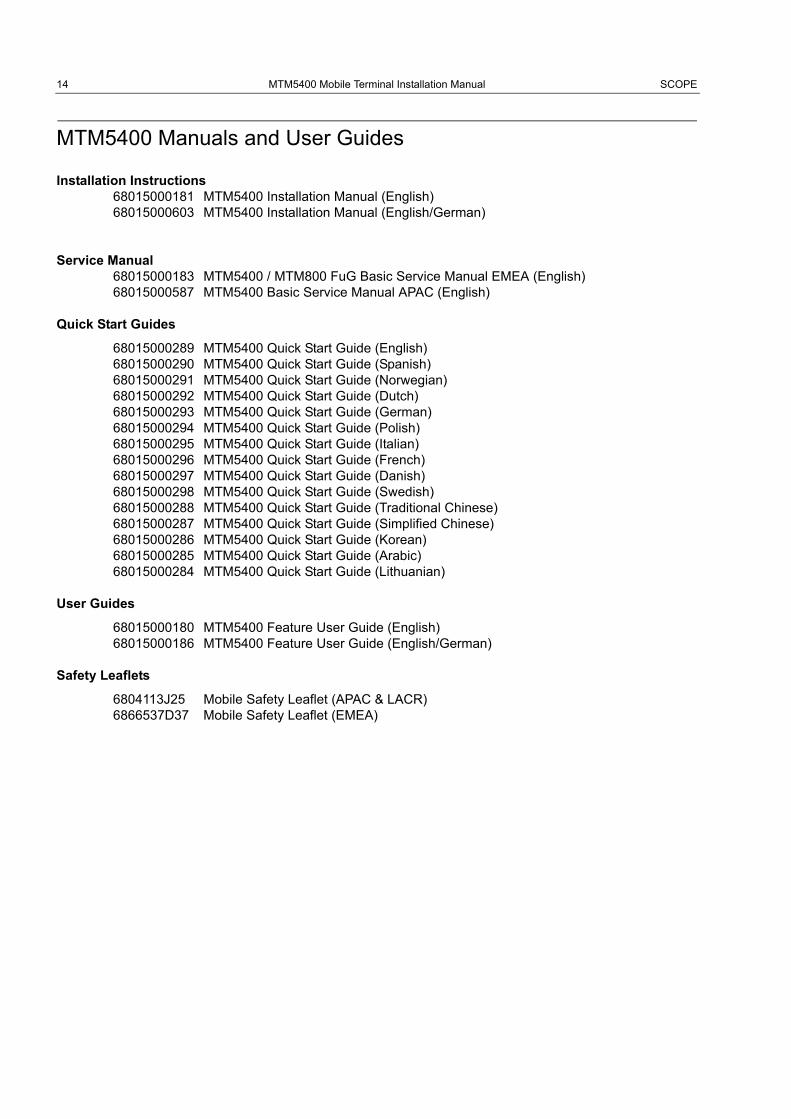
MTM5400 Manuals and User Guides
Installation Instructions68015000181 MTM5400 Installation Manual (English)68015000603 MTM5400 Installation Manual (English/German)
Service Manual68015000183 MTM5400 / MTM800 FuG Basic Service Manual EMEA (English)68015000587 MTM5400 Basic Service Manual APAC (English)
Quick Start Guides
68015000289 MTM5400 Quick Start Guide (English)68015000290 MTM5400 Quick Start Guide (Spanish)68015000291 MTM5400 Quick Start Guide (Norwegian)68015000292 MTM5400 Quick Start Guide (Dutch)68015000293 MTM5400 Quick Start Guide (German)68015000294 MTM5400 Quick Start Guide (Polish)68015000295 MTM5400 Quick Start Guide (Italian)68015000296 MTM5400 Quick Start Guide (French)68015000297 MTM5400 Quick Start Guide (Danish)68015000298 MTM5400 Quick Start Guide (Swedish)68015000288 MTM5400 Quick Start Guide (Traditional Chinese)68015000287 MTM5400 Quick Start Guide (Simplified Chinese)68015000286 MTM5400 Quick Start Guide (Korean)68015000285 MTM5400 Quick Start Guide (Arabic)68015000284 MTM5400 Quick Start Guide (Lithuanian)
User Guides
68015000180 MTM5400 Feature User Guide (English)68015000186 MTM5400 Feature User Guide (English/German)
Safety Leaflets
6804113J25 Mobile Safety Leaflet (APAC & LACR)6866537D37 Mobile Safety Leaflet (EMEA)

SCOPE MTM5400 Mobile Terminal Installation Manual 15
Warranty and Service Support
Motorola offers long term support for its products. This support includes full exchange and/or repair
of the product during the warranty period, and service/ repair or spare parts support out of warranty.
Prior to shipping any terminal back to the appropriate Motorola warranty depot, please contact
Customer Resources or your Motorola dealer, distributor or reseller.
All returns must be accompanied by a Warranty Claim Form, available from your Customer Service
representative or Motorola Online Extranet (MOL) or your Motorola dealer, distributor or reseller.
Warranty Period and Return Instructions
The terms and conditions of warranty are defined fully in the Motorola Customer, Dealer or
Distributor or Reseller contract. These conditions may change from time to time and the following
notes are for guidance purposes only.
In instances where the product is covered under a "return for replacement" or "return for repair"
warranty, a check of the product should be performed prior to shipping the unit back to Motorola.
This is to ensure that the product has been correctly programmed or has not been subjected to
damage outside the terms of the warranty.
Prior to shipping any terminal back to the appropriate Motorola warranty depot, please contact
Customer Resources (please refer to following pages). All returns must be accompanied by a
Warranty Claim Form, available from your Customer Services representative. Products should be
shipped back in the original packaging, or correctly packaged to ensure no damage occurs in transit.
After Warranty Period
After the Warranty period, Motorola continues to support its products in two ways.
• Motorola's Regional Radio Support Centres offer a repair service to both end users and
dealers at competitive prices.
• AAD supplies individual parts and modules that can be purchased by dealers who are
technically capable of performing fault analysis and repair.
16 MTM5400 Mobile Terminal Installation Manual SCOPE
Service Information
Europe, Middle East and Africa Region
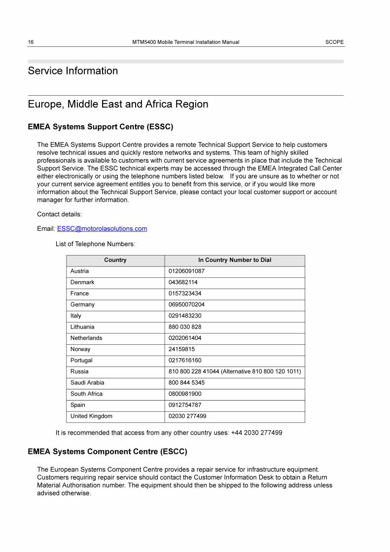
EMEA Systems Support Centre (ESSC)
The EMEA Systems Support Centre provides a remote Technical Support Service to help customers
resolve technical issues and quickly restore networks and systems. This team of highly skilled
professionals is available to customers with current service agreements in place that include the Technical
Support Service. The ESSC technical experts may be accessed through the EMEA Integrated Call Center
either electronically or using the telephone numbers listed below. If you are unsure as to whether or not
your current service agreement entitles you to benefit from this service, or if you would like more
information about the Technical Support Service, please contact your local customer support or account
manager for further information.
Contact details:
Email: [email protected]
List of Telephone Numbers:
It is recommended that access from any other country uses: +44 2030 277499
EMEA Systems Component Centre (ESCC)
The European Systems Component Centre provides a repair service for infrastructure equipment.
Customers requiring repair service should contact the Customer Information Desk to obtain a Return
Material Authorisation number. The equipment should then be shipped to the following address unless
advised otherwise.
Country In Country Number to Dial
Austria 01206091087
Denmark 043682114
France 0157323434
Germany 06950070204
Italy 0291483230
Lithuania 880 030 828
Netherlands 0202061404
Norway 24159815
Portugal 0217616160
Russia 810 800 228 41044 (Alternative 810 800 120 1011)
Saudi Arabia 800 844 5345
South Africa 0800981900
Spain 0912754787
United Kingdom 02030 277499
SCOPE MTM5400 Mobile Terminal Installation Manual 17
Motorola GmbH, European Systems Component Centre, Am Borsigturm 130, 13507 Berlin, Germany
Contact details:
Email: [email protected]
Telephone Number: +49 30 66861555
Fax: +49 30 66861426
Mon - Fri 08:00 am to 06:00 pm (CET)
Parts Identification and Ordering
Request for help in identification of non-referenced spare parts should be directed to the Customer Care
Organization of Motorola’s local area representation. Orders for replacement parts, kits and assemblies
should be placed directly on Motorola’s local distribution organization or via the Extranet site Motorola
Online at https://emeaonline.motorola.com.
EMEA Test Equipment Support
Information related to support and service of Motorola Test Equipment is available by calling the Motorola
Test Equipment Service Group in Germany at +49 (0) 6128 702179, Telefax +49 (0) 6128 951046, through
the Customer Care Organization of Motorola’s local area representation, or via the Internet at
http://www.gd-decisionsystems.com/cte/.
Your Input
...is much appreciated. If you have any comments, corrections, suggestions or ideas for this publication or
any other requirements regarding Motorola publications, please send an e-mail to
Updated Versions of this Manual
...are available at our Extranet site Motorola Online. Contact us at [email protected] for access.

18 MTM5400 Mobile Terminal Installation Manual SCOPE
Asia, Pacific Region
Piece Parts
Some replacement parts, spare parts, and/or product information can be ordered directly. If a
complete Motorola part number is assigned to the part, it is available from Motorola Radio
Aftermarket and Accessory Division (AAD). If no part number is assigned, the part is not normally
available from Motorola. If a parts list is not included, this generally means that no user-serviceable
parts are available for that kit or assembly.
Note on this digital TETRA Terminal: The CPS has no capability to tune the terminal. Tuning the
terminal can only be performed at the factory or at the appropriate Motorola Repair Centre.
Component replacement can affect the terminal tuning and must only be performed by the
appropriate Motorola Repair Centre.
All orders for parts/information should include the complete Motorola identification number. All part
orders should be directed to your local AAD office. Please refer to your latest price pages.
Technical Support
Technical support is available to assist the dealer/distributor in resolving any malfunction which may
be encountered. Initial contact should be by telephone wherever possible.
When contacting Motorola Technical Support, be prepared to provide the product model number
and the unit’s serial number.
Further Assistance from Motorola
You can also contact the Customer Help Desk through the following web address:
http://www.motorola.com/tetra.
Parts Identification and Ordering
Request for help in identification of non-referenced spare parts should be directed to the Customer
Care Organization of Motorola’s local area representation. Orders for replacement parts, kits and
assemblies should be placed directly on Motorola’s local distribution organization or via Motorola
Online (Extranet).
SCOPE MTM5400 Mobile Terminal Installation Manual 19
Latin America Region
Latin America Radio Support Centres
The Customer Support is available through the
following service centres:
Warranty and Repairs:
MOTOROLA DE COLOMBIA SERVICE
CENTRE
Torre Banco Ganadero
Carrera 7 No. 71-52
Torre B piso 13
Oficina 1301
Bogota - Colombia
(571) 376-6990
MOTOROLA DE MEXICO SERVICE CENTRE
Bosques de Alisos #125
Col. Bosques de las Lomas
CP 05120 Mexico DF
5252576700
Piece Parts:To order parts in Latin America and the
Caribbean contact your local Motorola CGISS
representative.
MOTOROLA, INC.
Latin American Countries Region
789 International Parkway
Sunrise, FL 33325
USA 954-723-8959
MOTOROLA DE ARGENTINA
Ave. del Libertador 1855
B1638BGE, Vicente Lopez
Buenos Aires, Argentina
5411-4317-5300
MOTOROLA DE LOS ANDES C.A.
Ave. Francisco de Miranda
Centro Lido, Torre A
Piso 15, El Rosal
Caracas, 1060 Venezuela
58212-901-4600
MOTOROLA DO BRASIL LTDA.
Av. Chedid Jafet
222 Bloco D Conjuntos 11,12,21,22 E 41
Condominio Millennium Office Park
04551-065- Vila Olimpia, Sao Paulo
Brasil
5511-3847-668
MOTOROLA CHILE
Ave. Nueva Tajamar 481
Edif. World Trade Center
Of. 1702, Torre Norte
Las Condes
Santiago, Chile
562-338-9000
MOTOROLA DE COLOMBIA, LTDA.
Carrera 7 #71-52
Torre A, Oficina 1301
Bogotá, Colombia
571-376-6990
MOTOROLA DE COSTA RICA
Parque Empresarial Plaza Roble
Edificio El Portico, 1er Piso
Centro de Negocios Internacional
Guachepelin, Escazu
San Jose, Costa Rica
506-201-1480
MOTOROLA DEL ECUADOR
Autopist Gral. Rumiñahui, Puente 2
Conjunto Puerta del Sol Este-Ciudad Jardin
Pasa E, Casa 65
Quito, Ecuador
5932-264-1627
MOTOROLA DE MEXICO, S.A.
Calle Bosques de Alisos #125
Col. Bosques de Las Lomas
05120 México D.F.
México
52-555-257-6700
MOTOROLA DEL PERU, S.A.
Ave. República de Panama 3535
Piso 11, San Isidro
Lima 27, Peru
511-211-0700
Technical Support:https://businessonline.motorola.com, go to
Contact Us to request technical support
Some replacement parts, spare parts, and/or
product information can be ordered directly. If a
complete Motorola part number is assigned to
the part, it is available from Motorola. If no part
number is assigned, the part is not normally
available from Motorola. If the part number is
appended with an asterisk, the part is
serviceable by Motorola Depot only. If a parts list
is not included, this generally means that no
user-serviceable parts are available for that kit
or assembly.

20 MTM5400 Mobile Terminal Installation Manual
THIS PAGE INTENTIONALLY LEFT BLANK
MODEL INFORMATION & ACCESSORIES MTM5400 Mobile Terminal Installation Manual 21
MODEL INFORMATION & ACCESSORIES
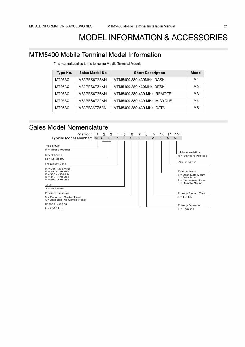
MTM5400 Mobile Terminal Model Information
This manual applies to the following Mobile Terminal Models
Sales Model Nomenclature
Type No. Sales Model No. Short Description Model
MT953C M83PFS6TZ5AN MTM5400 380-430MHz, DASH M1
MT953C M83PFS6TZ4AN MTM5400 380-430MHz, DESK M2
MT953C M83PFS6TZ6AN MTM5400 380-430 MHz, REMOTE M3
MT953C M83PFS6TZ2AN MTM5400 380-430 MHz, M’CYCLE M4
MT953C M83PFA6TZ5AN MTM5400 380-430 MHz, DATA M5
Typical Model Number: M 8 3 P F S 6 T Z 5 A N Position: 2 3 1 4 5 7 10 9 11 128 6
Type of Unit
M = Mobile Product
Model Series
83 = MTM5400
Frequency Band
M = 260 - 275 MHzN = 350 - 390 MHzP = 380 - 430 MHzR = 410 - 470 MHzU = 806 - 870 MHz
Level
Physical Packages
S = Enhanced Control HeadA = Data Box (No Control Head)
Channel Spacing
6 = 20/25 kHz
Unique VariationN = Standard Package
Version Letter
Feature Level5 = Dash/Data Mount4 = Desk Mount2 = Motorcycle Mount6 = Remote Mount
Primary System TypeZ = TETRA
Primary OperationT = Trunking
F = 10.0 Watts
22 MTM5400 Mobile Terminal Installation Manual MODEL INFORMATION & ACCESSORIES
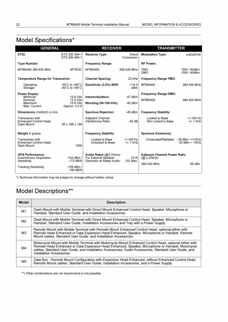
Model Specifications*
*) Technical information may be subject to change without further notice.
Model Descriptions**
**) Other combinations are not recommend or not possible.
GENERAL RECEIVER TRANSMITTER
ETSI: ETS 300 394-1 ETS 300 489-1
Receiver Type: Direct Conversion
Modulation Type: π/4DQPSK
Type Number: Frequency Range: RF Power:
MTM5400 380-430 MHz MT953C MTM5400 380-430 MHz TMODMO
10W / 40dBm 10W / 40dBm
Temperature Range for Transceiver: Channel Spacing: 25 kHz Frequency Range TMO:
Operating
Storage:-30°C to +60°C -40°C to +85°C
Sensitivity (3.5%) BER: -114.5 dBm
MTM5400 380-430 MHz
Power Supply:Minimum:Nominal:Maximum:Max. Current
10.8 Vdc13.2 Vdc15.6 Vdc
Approx. 4.5 A
Intermodulation:
Blocking (50-100 kHz):
-47 dBm
-40 dBm
Frequency Range DMO:
MTM5400 380-430 MHz
Dimensions (HxWxD) in mm: Spurious Rejection: -45 dBm Frequency Stability:
Transceiver withEnhanced Control Head, Dash Mount 60 x 188 x 198
Adjacent ChannelInterference Ratio: -45 dB
Locked to BaseNot Locked to Base
+/-100 Hz+/- 1 kHz
Weight in grams: Frequency Stability: Spurious Emissions:
Transceiver with Enhanced Control Head, Dash Mount 1500
Locked to BaseUnlocked to Base
+/-100 Hz +/- 1 kHz
Conducted/Radiated - 36 dBm <=1GHz - 30 dBm > 1GHz
GPS PerformanceAutonomous Acquisition Sensitivity
Tracking Sensitivity
-143 dBm / -173 dBW
-159 dBm / - 189 dBW
Audio Rated (@4 Ohms):For External Speaker:Distortion at Rated Audio:
10 W5% Max.
Adjacent Channel Power Ratio (@ ± 25kHz)
380-430 MHz - 60 dBc
Model Description
M1Dash Mount with Mobile Terminal with Direct Mount Enhanced Control Head, Speaker, Microphone or Handset, Standard User Guide, and Installation Accessories.
M2Desk Mount with Mobile Terminal with Direct Mount Enhanced Control Head, Speaker, Microphone or Handset, Standard User Guide, Installation Accessories and Tray with a Power Supply.
M3Remote Mount with Mobile Terminal with Remote Mount Enhanced Control Head, optional either with Remote Head Enhanced or Data Expansion Head Enhanced, Speaker, Microphone or Handset, Remote Mount cables, Standard User Guide, and Installation Accessories.
M4
Motorcycle Mount with Mobile Terminal with Motorcycle Mount Enhanced Control Head, optional either with Remote Head Enhanced or Data Expansion Head Enhanced, Speaker, Microphone or Handset, Motorcycle cables, Standard User Guide, and Installation Accessories; Audio Accessories, Standard User Guide, and Installation Accessories.
M5Data Box - Remote Mount Configuration with Expansion Head Enhanced, without Enhanced Control Head, Remote Mount cables, Standard User Guide, Installation Accessories, and a Power Supply.
MODEL INFORMATION & ACCESSORIES MTM5400 Mobile Terminal Installation Manual 23
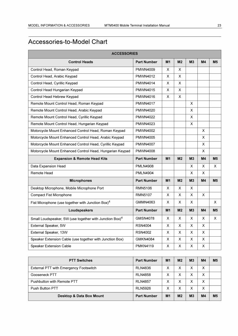
Accessories-to-Model Chart
ACCESSORIES
Control Heads Part Number M1 M2 M3 M4 M5
Control Head, Roman Keypad PMWN4009 X X
Control Head, Arabic Keypad PMWN4012 X X
Control Head, Cyrillic Keypad PMWN4014 X X
Control Head Hungarian Keypad PMWN4015 X X
Control Head Hebrew Keypad PMWN4016 X X
Remote Mount Control Head, Roman Keypad PMWN4017 X
Remote Mount Control Head, Arabic Keypad PMWN4020 X
Remote Mount Control Head, Cyrillic Keypad PMWN4022 X
Remote Mount Control Head, Hungarian Keypad PMWN4023 X
Motorcycle Mount Enhanced Control Head, Roman Keypad PMWN4002 X
Motorcycle Mount Enhanced Control Head, Arabic Keypad PMWN4005 X
Motorcycle Mount Enhanced Control Head, Cyrillic Keypad PMWN4007 X
Motorcycle Mount Enhanced Control Head, Hungarian Keypad PMWN4008 X
Expansion & Remote Head Kits Part Number M1 M2 M3 M4 M5
Data Expansion Head PMLN4908 X X X
Remote Head PMLN4904 X X
Microphones Part Number M1 M2 M3 M4 M5
Desktop Microphone, Mobile Microphone Port RMN5106 X X X
Compact Fist Microphone RMN5107 X X X X
Fist Microphone (use together with Junction Box)4 GMMN4063 X X X X
Loudspeakers Part Number M1 M2 M3 M4 M5
Small Loudspeaker, 5W (use together with Junction Box)4 GMSN4078 X X X X X
External Speaker, 5W RSN4004 X X X X
External Speaker, 13W RSN4002 X X X X
Speaker Extension Cable (use together with Junction Box) GMKN4084 X X X X
Speaker Extension Cable PMKN4119 X X X X
PTT Switches Part Number M1 M2 M3 M4 M5
External PTT with Emergency Footswitch RLN4836 X X X X
Gooseneck PTT RLN4858 X X X X
Pushbutton with Remote PTT RLN4857 X X X X
Push Button PTT RLN5926 X X X X
Desktop & Data Box Mount Part Number M1 M2 M3 M4 M5
24 MTM5400 Mobile Terminal Installation Manual MODEL INFORMATION & ACCESSORIES
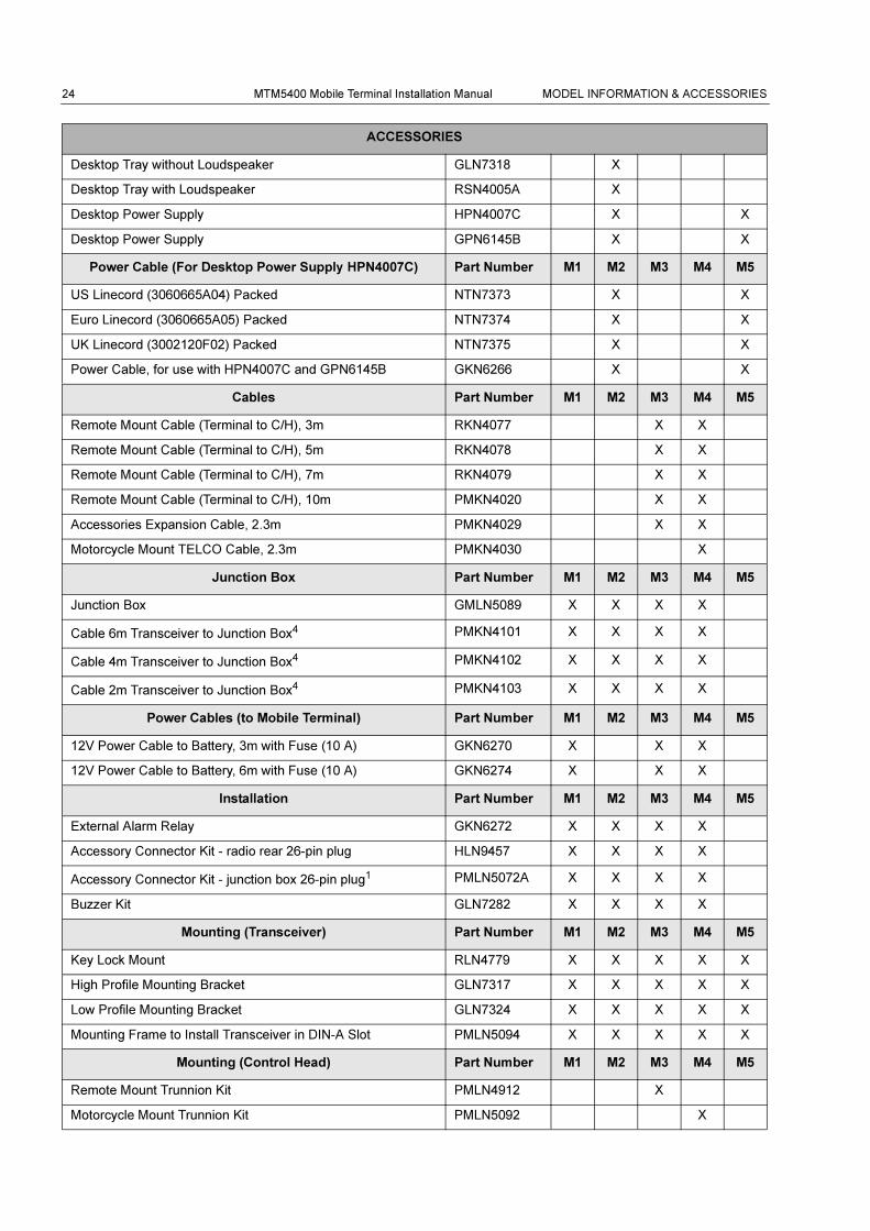
Desktop Tray without Loudspeaker GLN7318 X
Desktop Tray with Loudspeaker RSN4005A X
Desktop Power Supply HPN4007C X X
Desktop Power Supply GPN6145B X X
Power Cable (For Desktop Power Supply HPN4007C) Part Number M1 M2 M3 M4 M5
US Linecord (3060665A04) Packed NTN7373 X X
Euro Linecord (3060665A05) Packed NTN7374 X X
UK Linecord (3002120F02) Packed NTN7375 X X
Power Cable, for use with HPN4007C and GPN6145B GKN6266 X X
Cables Part Number M1 M2 M3 M4 M5
Remote Mount Cable (Terminal to C/H), 3m RKN4077 X X
Remote Mount Cable (Terminal to C/H), 5m RKN4078 X X
Remote Mount Cable (Terminal to C/H), 7m RKN4079 X X
Remote Mount Cable (Terminal to C/H), 10m PMKN4020 X X
Accessories Expansion Cable, 2.3m PMKN4029 X X
Motorcycle Mount TELCO Cable, 2.3m PMKN4030 X
Junction Box Part Number M1 M2 M3 M4 M5
Junction Box GMLN5089 X X X X
Cable 6m Transceiver to Junction Box4 PMKN4101 X X X X
Cable 4m Transceiver to Junction Box4 PMKN4102 X X X X
Cable 2m Transceiver to Junction Box4 PMKN4103 X X X X
Power Cables (to Mobile Terminal) Part Number M1 M2 M3 M4 M5
12V Power Cable to Battery, 3m with Fuse (10 A) GKN6270 X X X
12V Power Cable to Battery, 6m with Fuse (10 A) GKN6274 X X X
Installation Part Number M1 M2 M3 M4 M5
External Alarm Relay GKN6272 X X X X
Accessory Connector Kit - radio rear 26-pin plug HLN9457 X X X X
Accessory Connector Kit - junction box 26-pin plug1 PMLN5072A X X X X
Buzzer Kit GLN7282 X X X X
Mounting (Transceiver) Part Number M1 M2 M3 M4 M5
Key Lock Mount RLN4779 X X X X X
High Profile Mounting Bracket GLN7317 X X X X X
Low Profile Mounting Bracket GLN7324 X X X X X
Mounting Frame to Install Transceiver in DIN-A Slot PMLN5094 X X X X X
Mounting (Control Head) Part Number M1 M2 M3 M4 M5
Remote Mount Trunnion Kit PMLN4912 X
Motorcycle Mount Trunnion Kit PMLN5092 X
ACCESSORIES
MODEL INFORMATION & ACCESSORIES MTM5400 Mobile Terminal Installation Manual 25
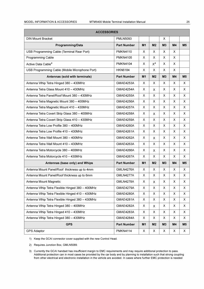
1) Keep the GCAI connector cover supplied with the new Control Head.
2) Requires Junction Box, GMLN5089.
3) Currently the GCAI handset has insufficient margin to EMC requirements and may require additional protection to pass.
Additional protection can in most cases be provided by the car body and by planning to installation such that strong coupling
from other electrical and electronic installation in the vehicle are avoided. In cases where further EMC protection is needed
DIN Mount Bracket PMLN5093 X
Programming/Data Part Number M1 M2 M3 M4 M5
USB Programming Cable (Terminal Rear Port) PMKN4110 X X X X
Programming Cable PMKN4105 X X X X
Active Data Cable4 PMKN4104 X X4 X X
USB Programming Cable (Mobile Microphone Port) HKN6184 X X X X
Antennas (sold with terminals) Part Number M1 M2 M3 M4 M5
Antenna Whip Tetra Hinged 380 – 430MHz GMAE4253A X X X X X
Antenna Tetra Glass Mount 410 – 430MHz GMAE4254A X X X X X
Antenna Tetra Panel/Roof Mount 380 – 430MHz GMAE4255A X X X X X
Antenna Tetra Magnetic Mount 380 – 400MHz GMAE4256A X X X X X
Antenna Tetra Magnetic Mount 410 – 430MHz GMAE4257A X X X X X
Antenna Tetra Covert Strip Glass 380 – 400MHz GMAE4258A X X X X X
Antenna Tetra Covert Strip Glass 410 – 430MHz GMAE4259A X X X X X
Antenna Tetra Low Profile 380 – 400MHz GMAE4260A X X X X X
Antenna Tetra Low Profile 410 – 430MHz GMAE4261A X X X X X
Antenna Tetra Wall Mount 380 – 400MHz GMAE4262A X X X X X
Antenna Tetra Wall Mount 410 – 430MHz GMAE4263A X X X X X
Antenna Tetra Motorcycle 380 – 400MHz GMAE4266A X X X X X
Antenna Tetra Motorcycle 410 – 430MHz GMAE4267A X X X X X
Antennas (base only) and Whips Part Number M1 M2 M3 M4 M5
Antenna Mount Panel/Roof thickness up to 4mm GMLN4276A X X X X X
Antenna Mount Panel/Roof thickness up to 6mm GMLN4277A X X X X X
Antenna Mount Magnetic GMLN4278A X X X X X
Antenna Whip Tetra Flexible Hinged 380 – 400MHz GMAE4279A X X X X X
Antenna Whip Tetra Flexible Hinged 410 – 430MHz GMAE4280A X X X X X
Antenna Whip Tetra Flexible Hinged 380 – 430MHz GMAE4281A X X X X X
Antenna Whip Tetra Hinged 380 – 400MHz GMAE4282A X X X X X
Antenna Whip Tetra Hinged 410 – 430MHz GMAE4283A X X X X X
Antenna Whip Tetra Hinged 380 – 430MHz GMAE4284A X X X X X
GPS Part Number M1 M2 M3 M4 M5
GPS Adaptor PMKN4114 X X X X X
ACCESSORIES

26 MTM5400 Mobile Terminal Installation Manual MODEL INFORMATION & ACCESSORIES
this can be achieved by installing (P/N: 01015001001) as shown in kit leaflet.
The specific configuration can be tested using the following technique:
The test requires a second radio in a quiet place or cooperation with a dispatcher.
1. Ensure that all other electrical and electronic equipment in the vehicle that may cause interference is not active.
2. Then check all intended RX and TX audio paths of the radio installation one at a time.
3. Listen to the idle channel noise and make sure there is no obvious noise or disturbance that can be attributed to radiated or
magnetically coupled interference. Speech must be clear over the channel.
4) The cable, PMKN4104, is only compatible when a Data Expansion Head Enhanced is not fitted as part of a remote mount
configuration. In this configuration access to the Tetra PEI for IP Packet Data and SDS services is available on the Data
Expansion Head Enhanced and the Active Data Cable PMKN4104 is not required.
INSTALLATION MTM5400 Mobile Terminal Installation Manual 27
INSTALLATION
Introduction
General Information
There are two methods of installing the mobile terminal in a vehicle:
1. Using the direct mounting trunnion and power cables supplied with a standard radio package.
2. Remote mounted in the car radio cut-out (using the required DIN mounting kit PMLN5094),
per ISO7736.
An accessory connector on the rear of the terminal enables you to attach different accessories (see
section “Accessory Connection Plan”).
A mobile microphone port on the front control head panel (see page 65) provides for the connection
of various types of microphones (Desktop Microphone RMN5106 or Compact Microphone
RMN5107).
1. Mount the terminal horizontally near the driver, so the driver can easily view, access and
operate the controls and accessories.
2. Ensure that the location is not exposed to dirt and moisture.
3. Verify that there will be sufficient space around the mobile unit for air flow and installation.
4. Check that there is enough routing space for the power cable connector and the antenna
coaxial cable.
5. Plan the best place to run connections to minimize pinching, crushing, and overheating of
wires and cables.
This product must be installed in a vehicle in accordance
with the vehicle manufacturer’s guidelines and the
instruction detailed in this manual.
Only the specified Motorola parts in this manual should be
used. Failure to do so could result in non compliance to
the Automotive Directive (72/245/EEC, as amended by
95/54/EC).
For products fitted to two and three wheeled vehicles,
Directive 97/24/EC applies.
This Terminal is only designed and certified to be used for
terrestrial use only.
This terminal is ONLY made for 12 V power supply
connection. In vehicles with 24 V power supply, a DC/DC
converter is required.
Please be aware when planning the installation that there
is a current consumption of approx. 4.5 A during PTT and
up to 30 mA when terminal is switched off.
28 MTM5400 Mobile Terminal Installation Manual INSTALLATION
DC Power Cable Installation
Installation Planning
The 3-meter (10-foot) DC power cable shipped with the terminal should be long enough to be
installed in most vehicles. Take the following precautions before you begin:
1. Whenever possible, avoid routing the cable above the catalytic converter.
2. Make sure that the power cable never rests on sharp edges.
3. Use grommets whenever a cable has to pass through a hole in a metal panel.
The following table lists power cables available for this terminal:
In a vehicle with an airbag, make sure that the mounting
location of the mobile terminal, or of any terminal
accessory, is not in the deployment path of the air bag.
Uninstaling the radio
OPTION 1:
Before disconnecting the 13.2 V main power supply from
the radio:
1. Switch off the radio.
2. Wait for a minimum of 4 seconds after the radio switch
is released.
3. Disconnect the 13.2 V main power supply.
OPTION 2:
Turn off the main power supply WITHOUT switching OFF
the radio.
This terminal must be operated only in negative ground
electrical systems. Operating the terminal on a positive
ground system will cause the cable fuse to short-circuit.
Check the vehicle ground polarity before you begin the
installation.
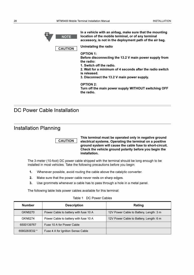
Table 1 DC Power Cables
Number Description Rating
GKN6270 Power Cable to battery with fuse 10 A 12V Power Cable to Battery, Length: 3 m
GKN6274 Power Cable to battery with fuse 10 A 12V Power Cable to Battery, Length: 6 m
6500139767 Fuse 10 A for Power Cable
6580283E02 * Fuse 4 A for Ignition Sense Cable
INSTALLATION MTM5400 Mobile Terminal Installation Manual 29
Installation Procedure
Begin the DC power cable installation as follows:
1. Determine a routing plan, keeping in mind where the terminal is to be mounted and make
sure that the cable does not rest on sharp edges.
2. Locate an existing hole with grommet in the vehicle fire wall, or use a 9.5 mm (3/8-inch) bit to
drill an access hole in the fire wall. Install a grommet with a 5 mm (3/16-inch) inside diameter
into the hole to protect the power cable.
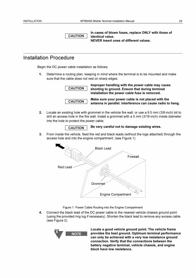
3. From inside the vehicle, feed the red and black leads (without the lugs attached) through the
access hole and into the engine compartment. (see Figure 1)
4. Connect the black lead of the DC power cable to the nearest vehicle chassis ground point
(using the provided ring lug if necessary). Shorten the black lead to remove any excess cable.
(see Figure 2).
In cases of blown fuses, replace ONLY with those of
identical value.
NEVER insert ones of different values.
Improper handling with the power cable may cause
shorting to ground. Ensure that during terminal
installation the power cable fuse is removed.
Make sure your power cable is not placed with the
antenna in parallel. Interference can cause radio to hang.
Be very careful not to damage existing wires.
Figure 1 Power Cable Routing into the Engine Compartment
Locate a good vehicle ground point. The vehicle frame
provides the best ground. Optimum terminal performance
can only be achieved with a very low resistance ground
connection. Verify that the connections between the
battery negative terminal, vehicle chassis, and engine
block have low resistance.
Black Lead
Red Lead
Grommet
Engine Compartment
Firewall
30 MTM5400 Mobile Terminal Installation Manual INSTALLATION
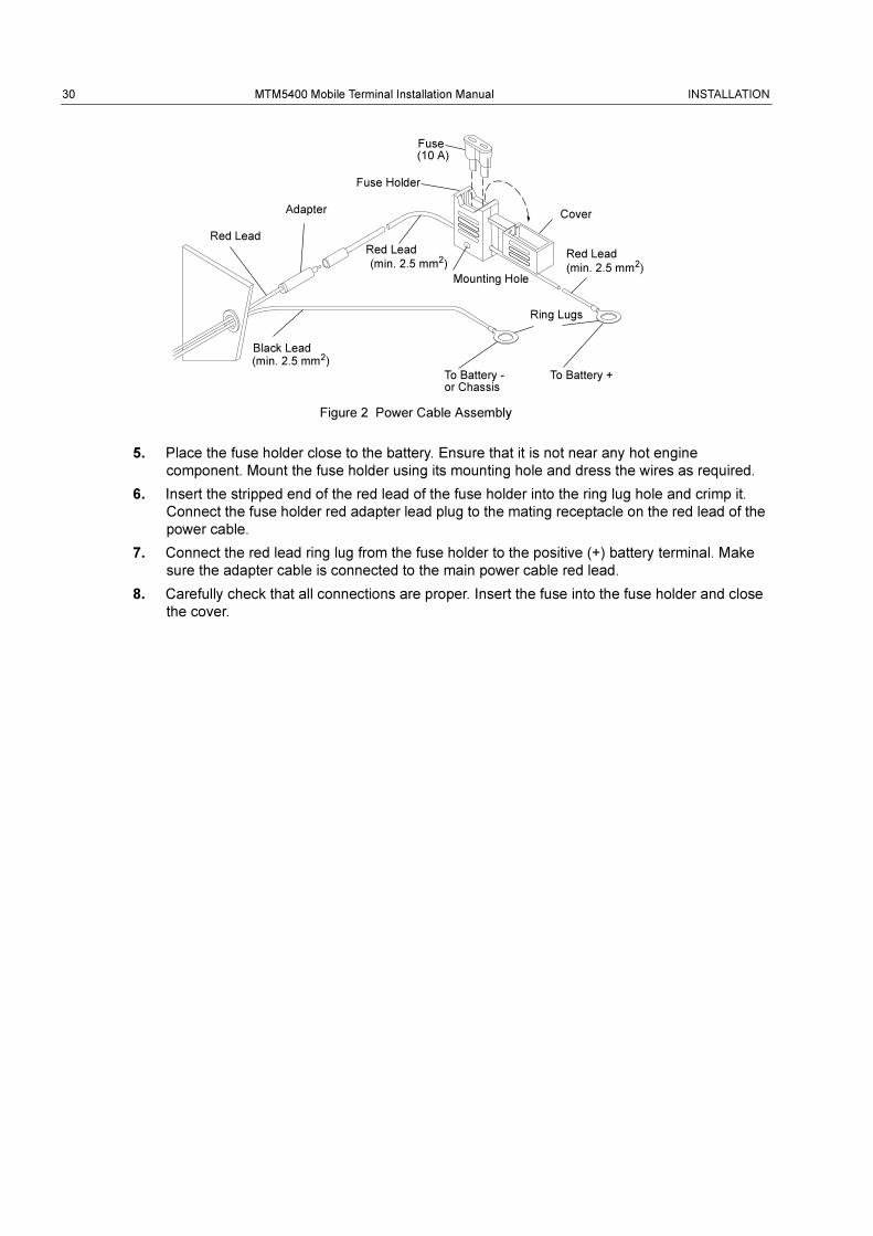
Figure 2 Power Cable Assembly
5. Place the fuse holder close to the battery. Ensure that it is not near any hot engine
component. Mount the fuse holder using its mounting hole and dress the wires as required.
6. Insert the stripped end of the red lead of the fuse holder into the ring lug hole and crimp it.
Connect the fuse holder red adapter lead plug to the mating receptacle on the red lead of the
power cable.
7. Connect the red lead ring lug from the fuse holder to the positive (+) battery terminal. Make
sure the adapter cable is connected to the main power cable red lead.
8. Carefully check that all connections are proper. Insert the fuse into the fuse holder and close
the cover.
Black Lead(min. 2.5 mm2)
To Battery - To Battery +
Red Lead
Fuse
Fuse Holder
Cover
Red Lead
(min. 2.5 mm2)Mounting Hole
(min. 2.5 mm2)
Red Lead
Adapter
Ring Lugs
(10 A)
or Chassis
INSTALLATION MTM5400 Mobile Terminal Installation Manual 31
Terminal Installation
Enhanced Control Head Installation
The Enhanced Control Head can be removed from the housing and turned to any position within a
180° radius. This provides multiple mounting options for the terminal. For example, the terminal may
be mounted on either side of the vehicle to facilitate the safest and most ergonomically ideal
position. The Enhanced Control Head may then be turned to provide the most convenient access.
To reposition the Enhanced Control Head:
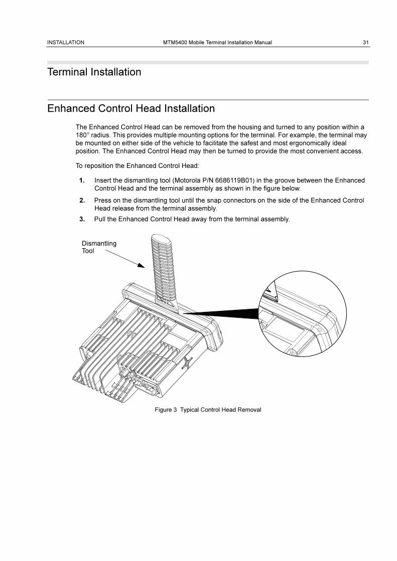
1. Insert the dismantling tool (Motorola P/N 6686119B01) in the groove between the Enhanced
Control Head and the terminal assembly as shown in the figure below.
2. Press on the dismantling tool until the snap connectors on the side of the Enhanced Control
Head release from the terminal assembly.
3. Pull the Enhanced Control Head away from the terminal assembly.
Figure 3 Typical Control Head Removal
Dismantling
ZWG0130209-O
Tool
32 MTM5400 Mobile Terminal Installation Manual INSTALLATION
Trunnion Installation
Installation Planning
The trunnion allows the terminal to be mounted to a variety of surfaces.
1. The trunnion must be securely fixed to the vehicle chassis.
2. Ensure the surface can support the weight of the terminal.
3. Although the trunnion can be mounted to a plastic dashboard, it is recommended that the
mounting screws be located so they penetrate the supporting metal frame of the dashboard.
4. Ground the radio housing to the nearest vehicle chassis ground point, which can be done by
removing the paint from the trunnion where the radio and vehicle chassis touches the
trunnion, or use a short cable with ring lugs in both end and connect this to chassis under
wingscrew.
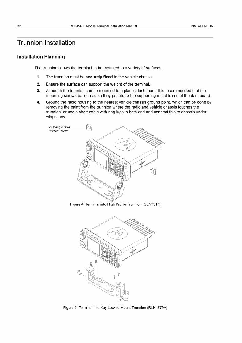
Figure 4 Terminal into High Profile Trunnion (GLN7317)
Figure 5 Terminal into Key Locked Mount Trunnion (RLN4779A)
2x Wingscrews
0305760W02
INSTALLATION MTM5400 Mobile Terminal Installation Manual 33
Installation Procedure
1. Select either the transmission hump or an open underneath portion of the dash to mount your
terminal (see Figure 6). When mounting the trunnion on the transmission hump, be careful
that the transmission housing is not affected.
2. Use the trunnion mounting bracket as a template, to mark the hole positions on the mounting
surface. Use the innermost three holes for a curved mounting surface, such as the
transmission hump, and the three outermost holes for a flat surface such as under the dash.
3. Centre-punch the spots you marked and use a 4 mm (5/32-inch) bit to drill a hole at each
location.
4. Secure the trunnion mounting bracket to the mounting surface with the three self-tapping
screws provided. (See Figure 6.)
5. Slide the terminal into the trunnion. Secure the terminal with the two wing screws provided.
6. Ground the radio housing to the nearest vehicle chassis ground point, which can be done by
removing the paint from the trunnion where the radio and vehicle chassis touches the
trunnion, or use a short cable with ring lugs in both end and connect this to chassis under
wingscrew.
The keypad labelling of the control head may vary
according to the specific customer/country concerns.
34 MTM5400 Mobile Terminal Installation Manual INSTALLATION
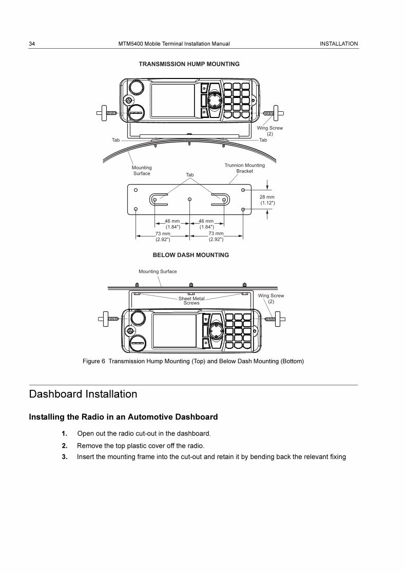
Figure 6 Transmission Hump Mounting (Top) and Below Dash Mounting (Bottom)
Dashboard Installation
Installing the Radio in an Automotive Dashboard
1. Open out the radio cut-out in the dashboard.
2. Remove the top plastic cover off the radio.
3. Insert the mounting frame into the cut-out and retain it by bending back the relevant fixing
46 mm (1.84")
73 mm(2.92")
73 mm(2.92")
46 mm (1.84")
28 mm (1.12")
Tab
BELOW DASH MOUNTING
Mounting Surface
MountingSurface
Tab
Wing Screw(2)
TRANSMISSION HUMP MOUNTING
Tab
Wing Screw(2)Sheet Metal
Screws
Trunnion MountingBracket
INSTALLATION MTM5400 Mobile Terminal Installation Manual 35
tabs, using all 6 where possible, to hold it in place.
4. Ground the mouting frame to the nearest vehicle chassis ground point.
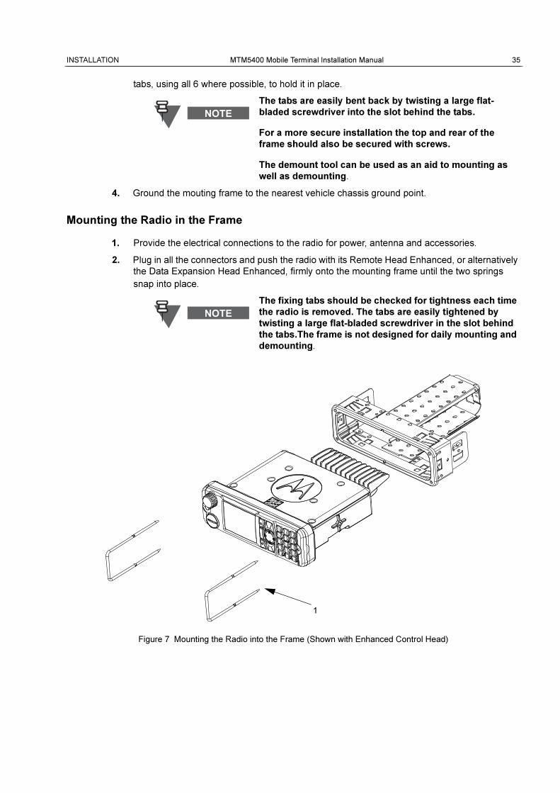
Mounting the Radio in the Frame
1. Provide the electrical connections to the radio for power, antenna and accessories.
2. Plug in all the connectors and push the radio with its Remote Head Enhanced, or alternatively
the Data Expansion Head Enhanced, firmly onto the mounting frame until the two springs
snap into place.
Figure 7 Mounting the Radio into the Frame (Shown with Enhanced Control Head)
The tabs are easily bent back by twisting a large flat-
bladed screwdriver into the slot behind the tabs.
For a more secure installation the top and rear of the
frame should also be secured with screws.
The demount tool can be used as an aid to mounting as
well as demounting.
The fixing tabs should be checked for tightness each time
the radio is removed. The tabs are easily tightened by
twisting a large flat-bladed screwdriver in the slot behind
the tabs.The frame is not designed for daily mounting and
demounting.
1

36 MTM5400 Mobile Terminal Installation Manual INSTALLATION
Table 2 DIN Mount Kit Components
Item Description Part Number
DIN Mount Kit PMLN5094
1 Demount Tool 8166514A01
INSTALLATION MTM5400 Mobile Terminal Installation Manual 37
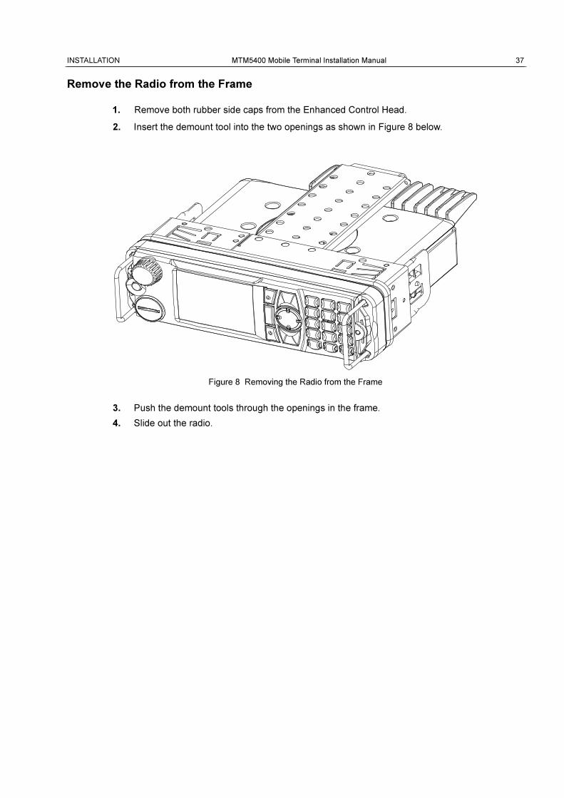
Remove the Radio from the Frame
1. Remove both rubber side caps from the Enhanced Control Head.
2. Insert the demount tool into the two openings as shown in Figure 8 below.
Figure 8 Removing the Radio from the Frame
3. Push the demount tools through the openings in the frame.
4. Slide out the radio.
38 MTM5400 Mobile Terminal Installation Manual INSTALLATION
Desktop Installation
The MTM5400 may be desktop mounted. The Desktop Station option provides the terminal with the
desk microphone, power supply, desk top tray (without speaker) and external loudspeaker.
Planning
Planning is the key to fast, easy terminal installation. Before a hole is drilled or a wire is run, inspect
the location and determine how and where you intend to mount the antenna, terminal and
accessories. Plan wire and cable runs to provide maximum protection from pinching, crushing, and
overheating. The installation planning should only be undertaken by persons who are competent
and able to ensure that the complete installation fulfils its regulatory requirements, such as EMC
(Electro Magnetic Compatibility) and IEC (International Electrotechnical Commission).
Installation
1. Be sure line voltage power is available.
2. Make sure sufficient air can flow around the terminal to permit adequate cooling.
3. Choose a flat surface for the desktop tray and external loudspeaker.
4. Be sure the mounting surface is able to adequately support the weight of the terminal and
tray.
5. If an outdoor antenna is used choose a location for the terminal as close as possible to the
antenna cable inlet of the building. Make sure that the installation of the surge protector is in
accordance with the manufacturer’s specifications and safety hints. The line voltage power
supply shall be grounded properly.
If an outdoor antenna is used a proper grounded Lightning
Protector with Quarter-Wave Shorting Stub must be
inserted between the outdoor antenna and the transceiver
antenna input. The line voltage power supply shall have a
proper ground connection (refer to IEC61312-1). The
installation must meet the requirements of any and all
applicable local codes and regulations.
INSTALLATION MTM5400 Mobile Terminal Installation Manual 39
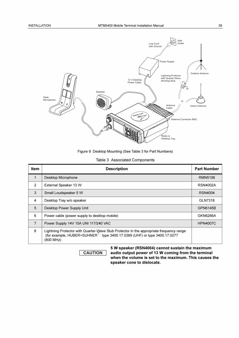
Figure 9 Desktop Mounting (See Table 3 for Part Numbers)
Table 3 Associated Components
Item Description Part Number
1 Desktop Microphone RMN5106
2 External Speaker 13 W RSN4002A
3 Small Loudspeaker 5 W RSN4004
4 Desktop Tray w/o speaker GLN7318
5 Desktop Power Supply Unit GPN6145B
6 Power cable (power supply to desktop mobile) GKN6266A
7 Power Supply 14V 15A UNI 117/240 VAC HPN4007C
8 Lightning Protector with Quarter-Wave Stub Protector in the appropriate frequency range
(for example, HUBER+SUHNER?
: type 3400.17.0389 (UHF) or type 3400.17.0277
(800 MHz)
5 W speaker (RSN4004) cannot sustain the maximum
audio output power of 13 W coming from the terminal
when the volume is set to the maximum. This causes the
speaker cone to dislocate.
Speaker
DeskMicrophone
Power Supply
WallOutlet
Indoor Antenna
Line Cord with Ground
12 V DesktopPower Cable
Antenna Cable
Antenna Connector BNC
Outdoor AntennaLightning Protector with Quarter-Wave Shorting Stub
or
CCCCCCCCCCCCCCCCCCCCCCCCCCCCCCCCCCCCCCCCCCCCCCCCCC Radio inDesktop Tray
40 MTM5400 Mobile Terminal Installation Manual INSTALLATION
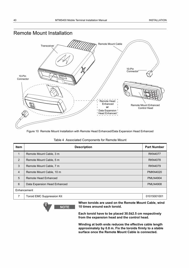
Remote Mount Installation
Figure 10 Remote Mount Installation with Remote Head Enhanced/Data Expansion Head Enhanced
Table 4 Associated Components for Remote Mount
Item Description Part Number
1 Remote Mount Cable, 3 m RKN4077
2 Remote Mount Cable, 5 m RKN4078
3 Remote Mount Cable, 7 m RKN4079
4 Remote Mount Cable, 10 m PMKN4020
5 Remote Head Enhanced PMLN4904
6 Data Expansion Head Enhanced PMLN4908
Enhancement
7 Toroid EMC Suppression Kit 01015001001
When toroids are used on the Remote Mount Cable, wind 10 times around each toroid.
Each toroid have to be placed 30.0±2.5 cm respectively from the expansion head and the control head.
Winding at both ends reduces the effective cable length approximately by 0.8 m. Fix the toroids firmly to a stable surface once the Remote Mount Cable is connected.
Transceiver
10-PinConnector
Remote Mount Cable
Remote Mount Enhanced
10-PinConnector
Remote Head
orData ExpansionHead Enhanced
EnhancedControl Head
INSTALLATION MTM5400 Mobile Terminal Installation Manual 41
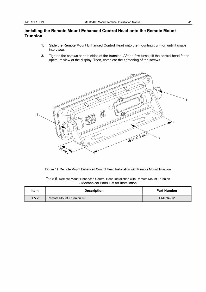
Installing the Remote Mount Enhanced Control Head onto the Remote Mount
Trunnion
1. Slide the Remote Mount Enhanced Control Head onto the mounting trunnion until it snaps
into place.
2. Tighten the screws at both sides of the trunnion. After a few turns, tilt the control head for an
optimum view of the display. Then, complete the tightening of the screws.
Figure 11 Remote Mount Enhanced Control Head Installation with Remote Mount Trunnion
Table 5 Remote Mount Enhanced Control Head Installation with Remote Mount Trunnion
- Mechanical Parts List for Installation
Item Description Part Number
1 & 2 Remote Mount Trunnion Kit PMLN4912
1
2
1
155+/-0.3 m
m
31 mm
42 MTM5400 Mobile Terminal Installation Manual INSTALLATION
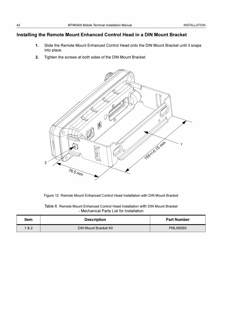
Installing the Remote Mount Enhanced Control Head in a DIN Mount Bracket
1. Slide the Remote Mount Enhanced Control Head onto the DIN Mount Bracket until it snaps
into place.
2. Tighten the screws at both sides of the DIN Mount Bracket.
Figure 12 Remote Mount Enhanced Control Head Installation with DIN Mount Bracket
Table 6 Remote Mount Enhanced Control Head Installation with DIN Mount Bracket
- Mechanical Parts List for Installation
Item Description Part Number
1 & 2 DIN Mount Bracket Kit PMLN5093
1
2 155+
/-0.1
5 mm
76.5 mm
INSTALLATION MTM5400 Mobile Terminal Installation Manual 43
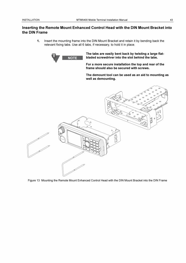
Inserting the Remote Mount Enhanced Control Head with the DIN Mount Bracket into
the DIN Frame
1. Insert the mounting frame into the DIN Mount Bracket and retain it by bending back the
relevant fixing tabs. Use all 6 tabs, if necessary, to hold it in place.
Figure 13 Mounting the Remote Mount Enhanced Control Head with the DIN Mount Bracket into the DIN Frame
The tabs are easily bent back by twisting a large flat-
bladed screwdriver into the slot behind the tabs.
For a more secure installation the top and rear of the
frame should also be secured with screws.
The demount tool can be used as an aid to mounting as
well as demounting.
44 MTM5400 Mobile Terminal Installation Manual INSTALLATION
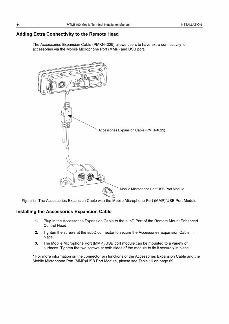
Adding Extra Connectivity to the Remote Head
The Accessories Expansion Cable (PMKN4029) allows users to have extra connectivity to
accessories via the Mobile Microphone Port (MMP) and USB port.
Figure 14 The Accessories Expansion Cable with the Mobile Microphone Port (MMP)/USB Port Module
Installing the Accessories Expansion Cable
1. Plug in the Accessories Expansion Cable to the subD Port of the Remote Mount Enhanced
Control Head.
2. Tighten the screws at the subD connector to secure the Accessories Expansion Cable in
place.
3. The Mobile Microphone Port (MMP)/USB port module can be mounted to a variety of
surfaces. Tighten the two screws at both sides of the module to fix it securely in place.
* For more information on the connector pin functions of the Accessories Expansion Cable and the
Mobile Microphone Port (MMP)/USB Port Module, please see Table 16 on page 69.
Accessories Expansion Cable (PMKN4029)
Mobile Microphone Port/USB Port Module
INSTALLATION MTM5400 Mobile Terminal Installation Manual 45
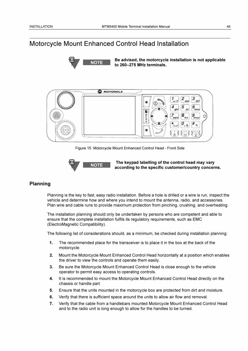
Motorcycle Mount Enhanced Control Head Installation
Figure 15 Motorcycle Mount Enhanced Control Head - Front Side
Planning
Planning is the key to fast, easy radio installation. Before a hole is drilled or a wire is run, inspect the
vehicle and determine how and where you intend to mount the antenna, radio, and accessories.
Plan wire and cable runs to provide maximum protection from pinching, crushing, and overheating.
The installation planning should only be undertaken by persons who are competent and able to
ensure that the complete installation fulfils its regulatory requirements, such as EMC
(ElectroMagnetic Compatibility).
The following list of considerations should, as a minimum, be checked during installation planning:
1. The recommended place for the transceiver is to place it in the box at the back of the
motorcycle.
2. Mount the Motorcycle Mount Enhanced Control Head horizontally at a position which enables
the driver to view the controls and operate them easily.
3. Be sure the Motorcycle Mount Enhanced Control Head is close enough to the vehicle
operator to permit easy access to operating controls.
4. It is recommended to mount the Motorcycle Mount Enhanced Control Head directly on the
chassis or handle part.
5. Ensure that the units mounted in the motorcycle box are protected from dirt and moisture.
6. Verify that there is sufficient space around the units to allow air flow and removal.
7. Verify that the cable from a handlebars mounted Motorcycle Mount Enhanced Control Head
and to the radio unit is long enough to allow for the handles to be turned.
Be advised, the motorcycle installation is not applicable
to 260–275 MHz terminals.
The keypad labelling of the control head may vary
according to the specific customer/country concerns.
46 MTM5400 Mobile Terminal Installation Manual INSTALLATION
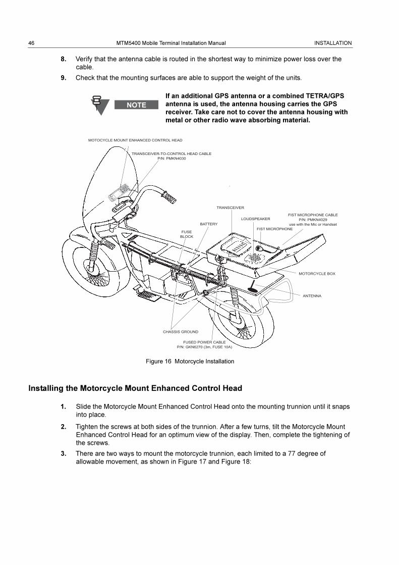
8. Verify that the antenna cable is routed in the shortest way to minimize power loss over the
cable.
9. Check that the mounting surfaces are able to support the weight of the units.
Figure 16 Motorcycle Installation
Installing the Motorcycle Mount Enhanced Control Head
1. Slide the Motorcycle Mount Enhanced Control Head onto the mounting trunnion until it snaps
into place.
2. Tighten the screws at both sides of the trunnion. After a few turns, tilt the Motorcycle Mount
Enhanced Control Head for an optimum view of the display. Then, complete the tightening of
the screws.
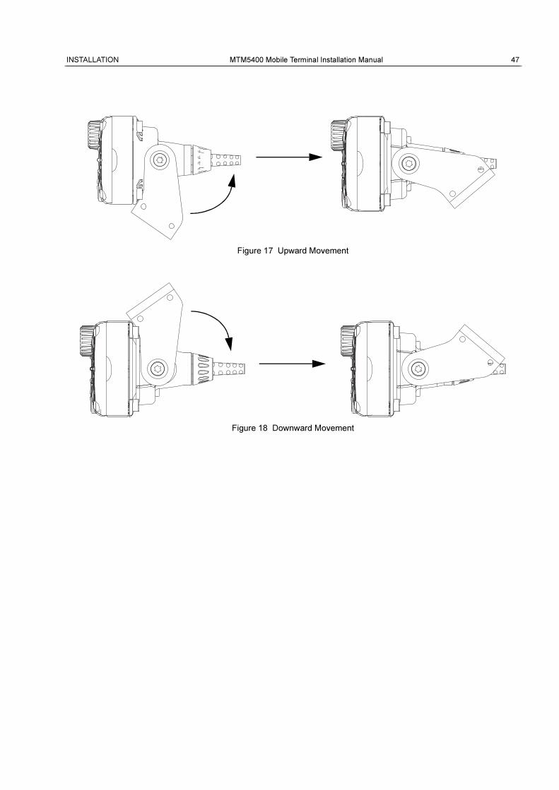
3. There are two ways to mount the motorcycle trunnion, each limited to a 77 degree of
allowable movement, as shown in Figure 17 and Figure 18:
If an additional GPS antenna or a combined TETRA/GPS
antenna is used, the antenna housing carries the GPS
receiver. Take care not to cover the antenna housing with
metal or other radio wave absorbing material.
TRANSCEIVER
LOUDSPEAKER
FIST MICROPHONE
MOTORCYCLE BOX
ANTENNA
BATTERY
FUSE BLOCK
CHASSIS GROUND
FUSED POWER CABLE P/N: GKN6270 (3m, FUSE 10A)
MOTOCYCLE MOUNT ENHANCED CONTROL HEAD
TRANSCEIVER-TO-CONTROL HEAD CABLE P/N: PMKN4030
FIST MICROPHONE CABLEP/N: PMKN4029
use with the Mic or Handset
INSTALLATION MTM5400 Mobile Terminal Installation Manual 47
Figure 17 Upward Movement
Figure 18 Downward Movement
48 MTM5400 Mobile Terminal Installation Manual INSTALLATION
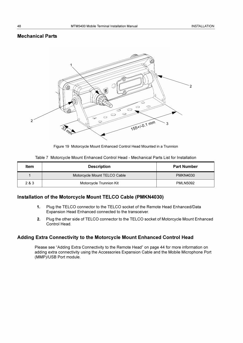
Mechanical Parts
Figure 19 Motorcycle Mount Enhanced Control Head Mounted in a Trunnion
Installation of the Motorcycle Mount TELCO Cable (PMKN4030)
1. Plug the TELCO connector to the TELCO socket of the Remote Head Enhanced/Data
Expansion Head Enhanced connected to the transceiver.
2. Plug the other side of TELCO connector to the TELCO socket of Motorcycle Mount Enhanced
Control Head.
Adding Extra Connectivity to the Motorcycle Mount Enhanced Control Head
Please see “Adding Extra Connectivity to the Remote Head” on page 44 for more information on
adding extra connectivity using the Accessories Expansion Cable and the Mobile Microphone Port
(MMP)/USB Port module.
Table 7 Motorcycle Mount Enhanced Control Head - Mechanical Parts List for Installation
Item Description Part Number
1 Motorcycle Mount TELCO Cable PMKN4030
2 & 3 Motorcycle Trunnion Kit PMLN5092
2
1
32
155+/-0.1 mm
33 mm
INSTALLATION MTM5400 Mobile Terminal Installation Manual 49
Data Expansion Head Enhanced Installation
Data Expansion Head Enhanced Radio without Control Head
The Data Expansion Head Enhanced can be used without a control head.
This configuration allows the use of the radio without any control head, allowing the radio to be
powered on via the ignition switch.
The packet data/SDS via the AT commands are available from the 9-pin subD connector (PEI).
The Remote PTT can be connected via the 26-pin rear connector. Only one talkgroup is available,
and that talkgroup is the first one on the CPS list.
50 MTM5400 Mobile Terminal Installation Manual INSTALLATION
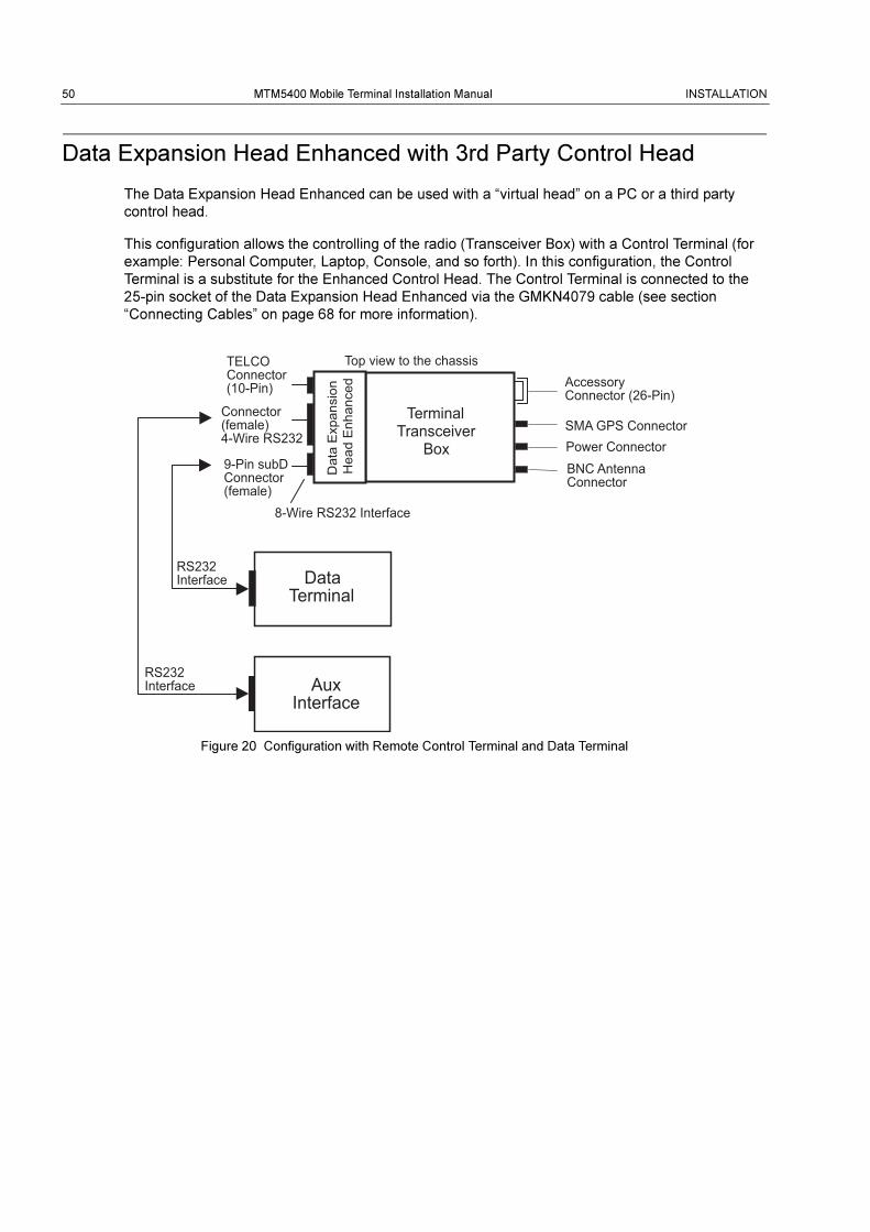
Data Expansion Head Enhanced with 3rd Party Control Head
The Data Expansion Head Enhanced can be used with a “virtual head” on a PC or a third party
control head.
This configuration allows the controlling of the radio (Transceiver Box) with a Control Terminal (for
example: Personal Computer, Laptop, Console, and so forth). In this configuration, the Control
Terminal is a substitute for the Enhanced Control Head. The Control Terminal is connected to the
25-pin socket of the Data Expansion Head Enhanced via the GMKN4079 cable (see section
“Connecting Cables” on page 68 for more information).
Figure 20 Configuration with Remote Control Terminal and Data Terminal
Accessory Connector (26-Pin)
Power Connector BNC Antenna Connector
SMA GPS Connector
8-Wire RS232 Interface
Data Terminal
Terminal Transceiver
Box
AuxInterface
TELCO Connector (10-Pin)
Connector(female)4-Wire RS232
9-Pin subD Connector (female)
RS232 Interface
Top view to the chassis
RS232 Interface
Dat
a E
xpan
sion
H
ead
Enh
ance
d
INSTALLATION MTM5400 Mobile Terminal Installation Manual 51
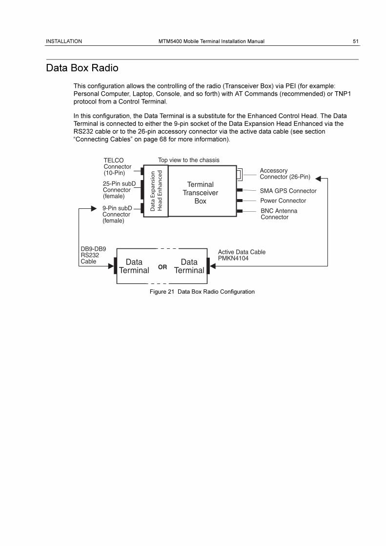
Data Box Radio
This configuration allows the controlling of the radio (Transceiver Box) via PEI (for example:
Personal Computer, Laptop, Console, and so forth) with AT Commands (recommended) or TNP1
protocol from a Control Terminal.
In this configuration, the Data Terminal is a substitute for the Enhanced Control Head. The Data
Terminal is connected to either the 9-pin socket of the Data Expansion Head Enhanced via the
RS232 cable or to the 26-pin accessory connector via the active data cable (see section
“Connecting Cables” on page 68 for more information).
Figure 21 Data Box Radio Configuration
DataTerminal
DataTerminal
TerminalTransceiver
Box
TELCOConnector(10-Pin)
25-Pin subDConnector(female)
9-Pin subDConnector(female)
DB9-DB9RS232Cable
Active Data CablePMKN4104
Top view to the chassisD
ata
Exp
ansi
on
Hea
d E
nh
ance
d
OR
AccessoryConnector (26-Pin)
Power Connector
BNC AntennaConnector
SMA GPS Connector
52 MTM5400 Mobile Terminal Installation Manual INSTALLATION
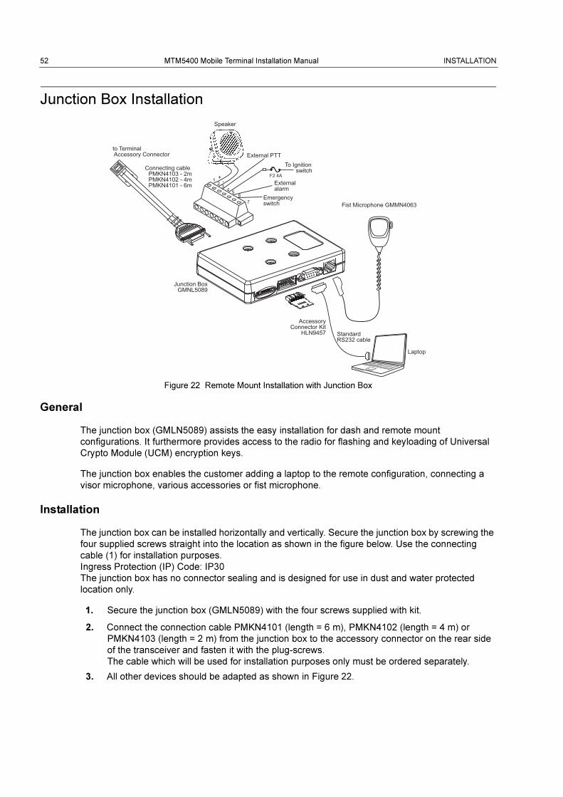
Junction Box Installation
Figure 22 Remote Mount Installation with Junction Box
General
The junction box (GMLN5089) assists the easy installation for dash and remote mount
configurations. It furthermore provides access to the radio for flashing and keyloading of Universal
Crypto Module (UCM) encryption keys.
The junction box enables the customer adding a laptop to the remote configuration, connecting a
visor microphone, various accessories or fist microphone.
Installation
The junction box can be installed horizontally and vertically. Secure the junction box by screwing the
four supplied screws straight into the location as shown in the figure below. Use the connecting
cable (1) for installation purposes.
Ingress Protection (IP) Code: IP30
The junction box has no connector sealing and is designed for use in dust and water protected
location only.
1. Secure the junction box (GMLN5089) with the four screws supplied with kit.
2. Connect the connection cable PMKN4101 (length = 6 m), PMKN4102 (length = 4 m) or
PMKN4103 (length = 2 m) from the junction box to the accessory connector on the rear side
of the transceiver and fasten it with the plug-screws.
The cable which will be used for installation purposes only must be ordered separately.
3. All other devices should be adapted as shown in Figure 22.
External alarm
Emergency switch
F2 4A
To Ignition switch
External PTT
Fist Microphone GMMN4063
Standard RS232 cable
Laptop
AccessoryConnector Kit
HLN9457
Connecting cable PMKN4103 - 2m
PMKN4102 - 4mPMKN4101 - 6m
Speaker
Junction BoxGMNL5089
to Terminal Accessory Connector
INSTALLATION MTM5400 Mobile Terminal Installation Manual 53
Service
The junction box PCB is not repairable. Please order a new junction box as necessary.
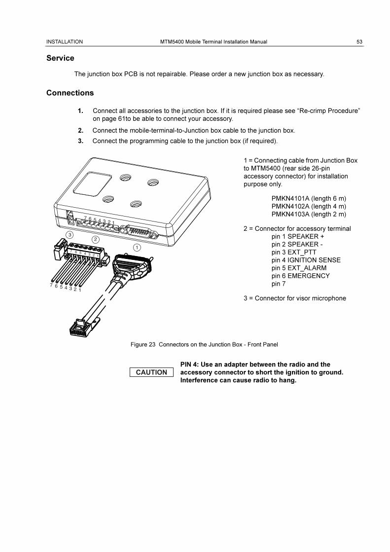
Connections
1. Connect all accessories to the junction box. If it is required please see “Re-crimp Procedure”
on page 61to be able to connect your accessory.
2. Connect the mobile-terminal-to-Junction box cable to the junction box.
3. Connect the programming cable to the junction box (if required).
Figure 23 Connectors on the Junction Box - Front Panel
PIN 4: Use an adapter between the radio and the
accessory connector to short the ignition to ground.
Interference can cause radio to hang.
1
23
7
7
6 5 4 3 2 1
6 5 4 3 2 1
1234567
1 = Connecting cable from Junction Box
to MTM5400 (rear side 26-pin
accessory connector) for installation
purpose only.
PMKN4101A (length 6 m)
PMKN4102A (length 4 m)
PMKN4103A (length 2 m)
2 = Connector for accessory terminal
pin 1 SPEAKER +
pin 2 SPEAKER -
pin 3 EXT_PTT
pin 4 IGNITION SENSE
pin 5 EXT_ALARM
pin 6 EMERGENCY
pin 7
3 = Connector for visor microphone
54 MTM5400 Mobile Terminal Installation Manual INSTALLATION
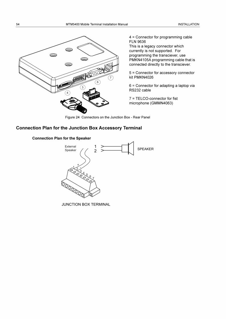
Figure 24 Connectors on the Junction Box - Rear Panel
Connection Plan for the Junction Box Accessory Terminal
Connection Plan for the Speaker
4
5
6
7
4 = Connector for programming cable
FLN 9636
This is a legacy connector which
currently is not supported. For
programming the transciever, use
PMKN4105A programming cable that is
connected directly to the transciever.
5 = Connector for accessory connector
kit PMKN4026
6 = Connector for adapting a laptop via
RS232 cable
7 = TELCO-connector for fist
microphone (GMMN4063)
12 SPEAKER
JUNCTION BOX TERMINAL
ExternalSpeaker
1 23 4 5 6 7
INSTALLATION MTM5400 Mobile Terminal Installation Manual 55
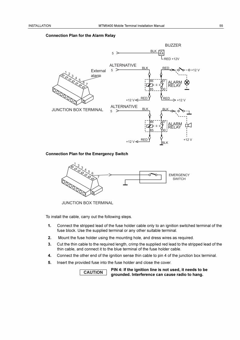
Connection Plan for the Alarm Relay
Connection Plan for the Emergency Switch
To install the cable, carry out the following steps.
1. Connect the stripped lead of the fuse holder cable only to an ignition switched terminal of the
fuse block. Use the supplied terminal or any other suitable terminal.
2. Mount the fuse holder using the mounting hole, and dress wires as required.
3. Cut the thin cable to the required length, crimp the supplied red lead to the stripped lead of the
thin cable, and connect it to the blue terminal of the fuse holder cable.
4. Connect the other end of the ignition sense thin cable to pin 4 of the junction box terminal.
5. Insert the provided fuse into the fuse holder and close the cover.
PIN 4: If the ignition line is not used, it needs to be
grounded. Interference can cause radio to hang.
5
5 ALTERNATIVE
ALTERNATIVE BLK
BLK
86 87
85 30
RED RED
BLK
ALARM RELAY
+12 V
ALARM RELAY
86 87
85 30
RED +12 V
BLK
5 BLK
RED +12V
BUZZER
+12 V
JUNCTION BOX TERMINAL
+12 V
RED +12 V
External alarm
1 2 3 4 5 6 7
EMERGENCY SWITCH
JUNCTION BOX TERMINAL
1 2 3 4 5 6 7
56 MTM5400 Mobile Terminal Installation Manual INSTALLATION
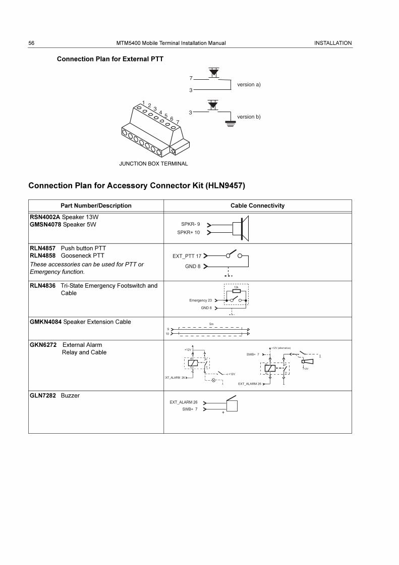
Connection Plan for External PTT
Connection Plan for Accessory Connector Kit (HLN9457)
Part Number/Description Cable Connectivity
RSN4002A Speaker 13W
GMSN4078 Speaker 5W
RLN4857 Push button PTT
RLN4858 Gooseneck PTT
These accessories can be used for PTT or
Emergency function.
RLN4836 Tri-State Emergency Footswitch and
Cable
GMKN4084 Speaker Extension Cable
GKN6272 External Alarm
Relay and Cable
GLN7282 Buzzer
JUNCTION BOX TERMINAL
version a)7
3
version b)3
1 23
45 6
7
SPKR- 9
SPKR+ 10
EXT_PTT 17
GND 8
Emergency 23
12k
GND 8
910
5m
86
85
87
30
+12V (alternative)
EXT_ALARM 26
+12V
SWB+ 786
85
87
30
+12V
EXT_ALARM 26+12V
EXT_ALARM 26
SWB+ 7

INSTALLATION MTM5400 Mobile Terminal Installation Manual 57
Radios with Data Expansion Head Enhanced
To use a junction box with one of the MTM5400 mobile terminals fitted with a Data Expansion Head
Enhanced, always use the 9-pin RS232 port on the Data Expansion Head Enhanced for PEI instead
of the 9-pin RS232 port on the junction box (connector 6). Ensure to fit a jumper between pins 6 and
15 of the Junction Box (connector 5) for the PEI to operate correctly in this configuration.
Standard Radios without Data Expansion Head Enhanced
For standard MTM5400 mobile terminals without a Data Expansion Head Enhanced, the jumper
between pins 6 and 15 of the junction box (connector 5) should be removed.
Table 8 Jumper on Accessory Connector
MTM5400 Mobile Terminal Fit Jumper Pins 6-15? Use Junction Box RS232 PEI?
With Data Expansion Head Enhanced Yes
No
Use the Data Expansion Head
Enhanced 9-pin PEI instead.
Without Data Expansion Head Enhanced No Yes
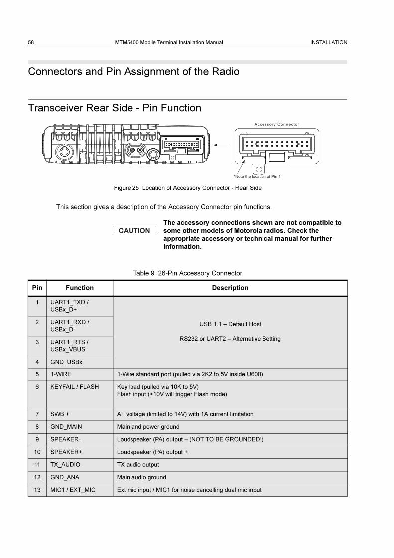
58 MTM5400 Mobile Terminal Installation Manual INSTALLATION
Connectors and Pin Assignment of the Radio
Transceiver Rear Side - Pin Function
Figure 25 Location of Accessory Connector - Rear Side
This section gives a description of the Accessory Connector pin functions.
The accessory connections shown are not compatible to
some other models of Motorola radios. Check the
appropriate accessory or technical manual for further
information.
Table 9 26-Pin Accessory Connector
Pin Function Description
1 UART1_TXD /
USBx_D+
USB 1.1 – Default Host
RS232 or UART2 – Alternative Setting
2 UART1_RXD /
USBx_D-
3 UART1_RTS /
USBx_VBUS
4 GND_USBx
5 1-WIRE 1-Wire standard port (pulled via 2K2 to 5V inside U600)
6 KEYFAIL / FLASH Key load (pulled via 10K to 5V)
Flash input (>10V will trigger Flash mode)
7 SWB + A+ voltage (limited to 14V) with 1A current limitation
8 GND_MAIN Main and power ground
9 SPEAKER- Loudspeaker (PA) output – (NOT TO BE GROUNDED!)
10 SPEAKER+ Loudspeaker (PA) output +
11 TX_AUDIO TX audio output
12 GND_ANA Main audio ground
13 MIC1 / EXT_MIC Ext mic input / MIC1 for noise cancelling dual mic input
*Note the location of Pin 1
Accessory Connector
2 26
1 25
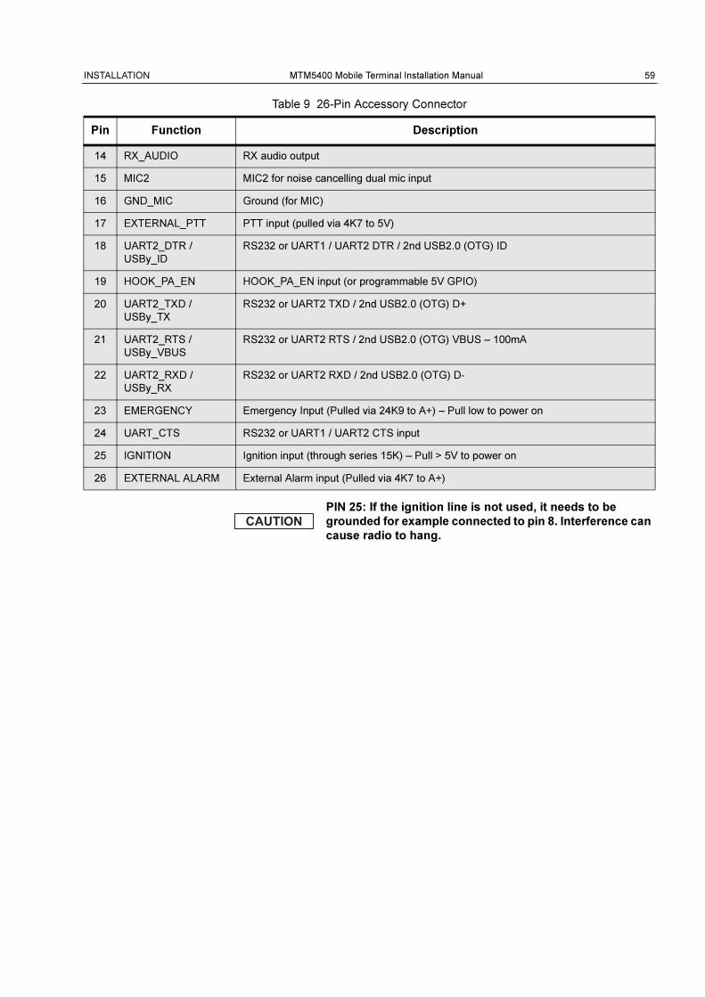
INSTALLATION MTM5400 Mobile Terminal Installation Manual 59
14 RX_AUDIO RX audio output
15 MIC2 MIC2 for noise cancelling dual mic input
16 GND_MIC Ground (for MIC)
17 EXTERNAL_PTT PTT input (pulled via 4K7 to 5V)
18 UART2_DTR /
USBy_ID
RS232 or UART1 / UART2 DTR / 2nd USB2.0 (OTG) ID
19 HOOK_PA_EN HOOK_PA_EN input (or programmable 5V GPIO)
20 UART2_TXD /
USBy_TX
RS232 or UART2 TXD / 2nd USB2.0 (OTG) D+
21 UART2_RTS /
USBy_VBUS
RS232 or UART2 RTS / 2nd USB2.0 (OTG) VBUS – 100mA
22 UART2_RXD /
USBy_RX
RS232 or UART2 RXD / 2nd USB2.0 (OTG) D-
23 EMERGENCY Emergency Input (Pulled via 24K9 to A+) – Pull low to power on
24 UART_CTS RS232 or UART1 / UART2 CTS input
25 IGNITION Ignition input (through series 15K) – Pull > 5V to power on
26 EXTERNAL ALARM External Alarm input (Pulled via 4K7 to A+)
PIN 25: If the ignition line is not used, it needs to be
grounded for example connected to pin 8. Interference can
cause radio to hang.
Table 9 26-Pin Accessory Connector
Pin Function Description
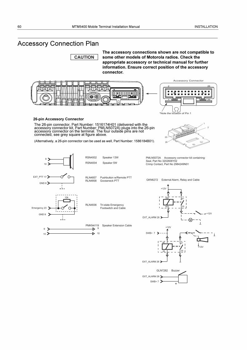
60 MTM5400 Mobile Terminal Installation Manual INSTALLATION
Accessory Connection Plan
The accessory connections shown are not compatible to
some other models of Motorola radios. Check the
appropriate accessory or technical manual for further
information. Ensure correct position of the accessory
connector.
26-pin Accessory Connector
25
26
1
2The 26-pin connector, Part Number: 1516174H01 (delivered with the accessory connector kit, Part Number: PMLN5072A) plugs into the 26-pin accessory connector on the terminal. The four outside pins are not connected, see grey square at figure above.
(Alternatively, a 26-pin connector can be used as well, Part Number: 1586184B01).
86
85
87
30
+12V
EXT_ALARM 26
86
85
87
30
+12V
EXT_ALARM 26
+12V
+12V
SWB+ 7
9
10
EXT_PTT 17
GND 8
Emergency 23
12k
GND 8
EXT_ALARM 26
SWB+ 7
RSN4002 Speaker 13W
RSN4004 Speaker 5W
RLN4857 Pushbutton w/Remote PTTRLN4858 Gooseneck PTT
RLN4836 Tri-state Emergency Footswitch and Cable
GLN7282 Buzzer
GKN6272 External Alarm, Relay and Cable
PMKN4119 Speaker Extension Cable
PMLN5072A Accessory connector kit containing:Seal, Part No 3202606Y02Crimp Contact, Part No 2984249N01
9
10
9
10
*Note the location of Pin 1
Accessory Connector
2 26
1 25
INSTALLATION MTM5400 Mobile Terminal Installation Manual 61
Re-crimp Procedure
In order to use accessories (RLN4858 and GKN6272) with the rear connector of the radio, please
follow the re-crimp procedure using the crimp pins provided with PMLN5072 connector kit.
1. Cut and remove nickel plated pins from wire.
2. Strip the insulation from the end of the wires (2mm to 4mm).
3. Place the new gold plated crimp pin (from the PMLN5072 kit) on the gauge slot on the crimp
tool.
4. Insert wire into wire slot of the crimp pin.
5. Apply pressure to the crimp tool handle, until wire is crimped by the pin.
These accessories do not require to be re-crimped when used
with the Junction Box GMLN5089.
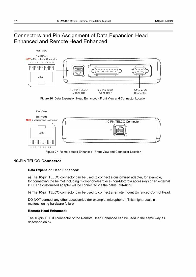
62 MTM5400 Mobile Terminal Installation Manual INSTALLATION
Connectors and Pin Assignment of Data Expansion Head Enhanced and Remote Head Enhanced
Figure 26 Data Expansion Head Enhanced - Front View and Connector Location
Figure 27 Remote Head Enhanced - Front View and Connector Location
10-Pin TELCO Connector
Data Expansion Head Enhanced:
a) The 10-pin TELCO connector can be used to connect a customized adapter, for example,
for connecting the helmet including microphone/earpiece (non-Motorola accessory) or an external
PTT. The customized adapter will be connected via the cable RKN4077.
b) The 10-pin TELCO connector can be used to connect a remote mount Enhanced Control Head.
DO NOT connect any other accessories (for example, microphone). This might result in
malfunctioning hardware failure.
Remote Head Enhanced:
The 10-pin TELCO connector of the Remote Head Enhanced can be used in the same way as
described on b).
Front View
CAUTION:NOT NOT a Microphone Connector
25-Pin subDConnector
9-Pin subDConnector
113
1425
15
69
10-Pin TELCOConnector
J302
1 2 3 4 5 6 7 8 9 10
Front View
CAUTION:NOT NOT a Microphone Connector
J302
12345678910
10-Pin TELCO Connector
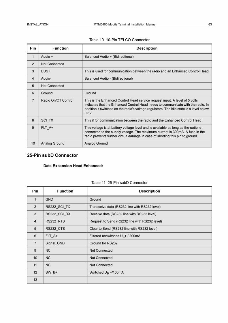
INSTALLATION MTM5400 Mobile Terminal Installation Manual 63
25-Pin subD Connector
Data Expansion Head Enhanced:
Table 10 10-Pin TELCO Connector
Pin Function Description
1 Audio + Balanced Audio + (Bidirectional)
2 Not Connected
3 BUS+ This is used for communication between the radio and an Enhanced Control Head.
4 Audio- Balanced Audio - (Bidirectional)
5 Not Connected
6 Ground Ground
7 Radio On/Off Control This is the Enhanced Control Head service request input. A level of 5 volts
indicates that the Enhanced Control Head needs to communicate with the radio. In
addition it switches on the radio's voltage regulators. The idle state is a level below
0.6V.
8 SCI_TX This if for communication between the radio and the Enhanced Control Head.
9 FLT_A+ This voltage is at battery voltage level and is available as long as the radio is
connected to the supply voltage. The maximum current is 300mA. A fuse in the
radio prevents further circuit damage in case of shorting this pin to ground.
10 Analog Ground Analog Ground
Table 11 25-Pin subD Connector
Pin Function Description
1 GND Ground
2 RS232_SCI_TX Transceive data (RS232 line with RS232 level)
3 RS232_SCI_RX Receive data (RS232 line with RS232 level)
4 RS232_RTS Request to Send (RS232 line with RS232 level)
5 RS232_CTS Clear to Send (RS232 line with RS232 level)
6 FLT_A+ Filtered unswitched UB+ / 200mA
7 Signal_GND Ground for RS232
9 NC Not Connected
10 NC Not Connected
11 NC Not Connected
12 SW_B+ Switched UB +/100mA
13
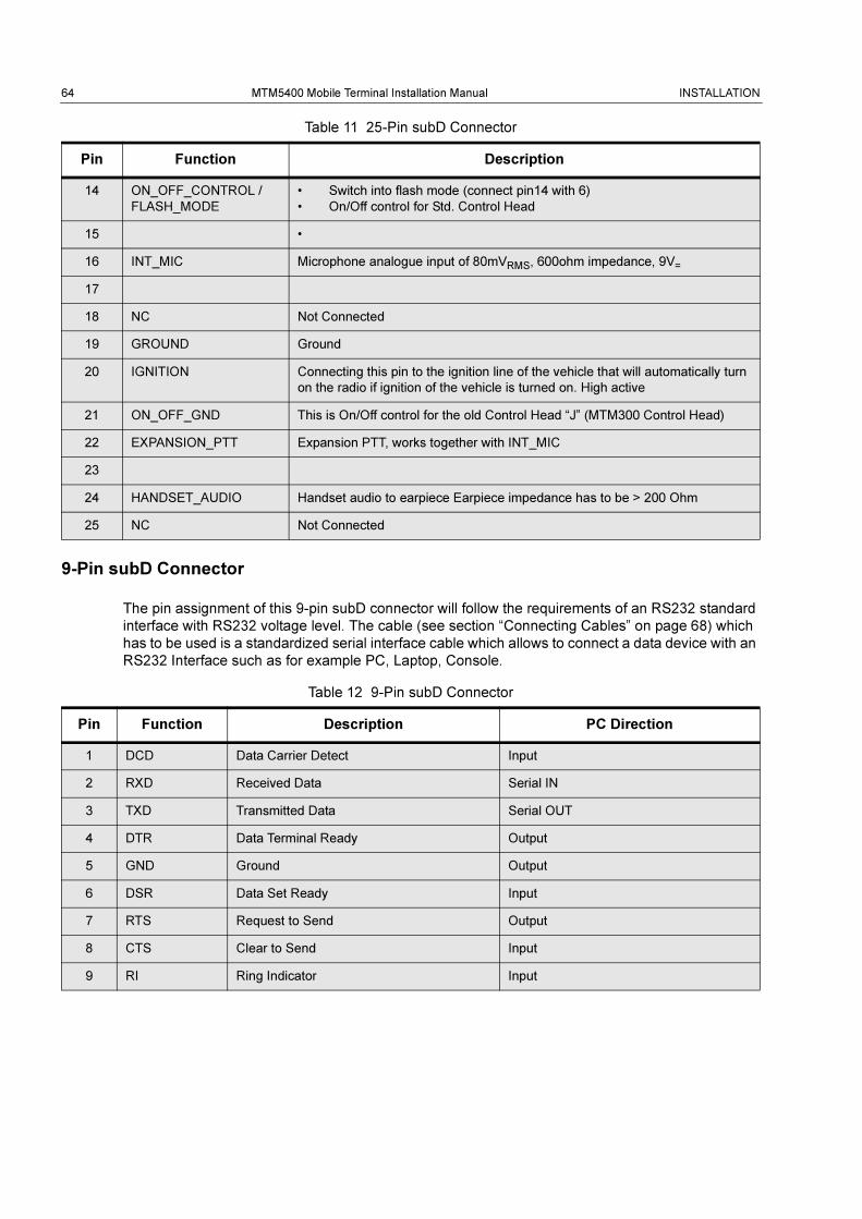
64 MTM5400 Mobile Terminal Installation Manual INSTALLATION
9-Pin subD Connector
The pin assignment of this 9-pin subD connector will follow the requirements of an RS232 standard
interface with RS232 voltage level. The cable (see section “Connecting Cables” on page 68) which
has to be used is a standardized serial interface cable which allows to connect a data device with an
RS232 Interface such as for example PC, Laptop, Console.
14 ON_OFF_CONTROL /
FLASH_MODE
• Switch into flash mode (connect pin14 with 6)
• On/Off control for Std. Control Head
15 •
16 INT_MIC Microphone analogue input of 80mVRMS, 600ohm impedance, 9V=
17
18 NC Not Connected
19 GROUND Ground
20 IGNITION Connecting this pin to the ignition line of the vehicle that will automatically turn
on the radio if ignition of the vehicle is turned on. High active
21 ON_OFF_GND This is On/Off control for the old Control Head “J” (MTM300 Control Head)
22 EXPANSION_PTT Expansion PTT, works together with INT_MIC
23
24 HANDSET_AUDIO Handset audio to earpiece Earpiece impedance has to be > 200 Ohm
25 NC Not Connected
Table 12 9-Pin subD Connector
Pin Function Description PC Direction
1 DCD Data Carrier Detect Input
2 RXD Received Data Serial IN
3 TXD Transmitted Data Serial OUT
4 DTR Data Terminal Ready Output
5 GND Ground Output
6 DSR Data Set Ready Input
7 RTS Request to Send Output
8 CTS Clear to Send Input
9 RI Ring Indicator Input
Table 11 25-Pin subD Connector
Pin Function Description
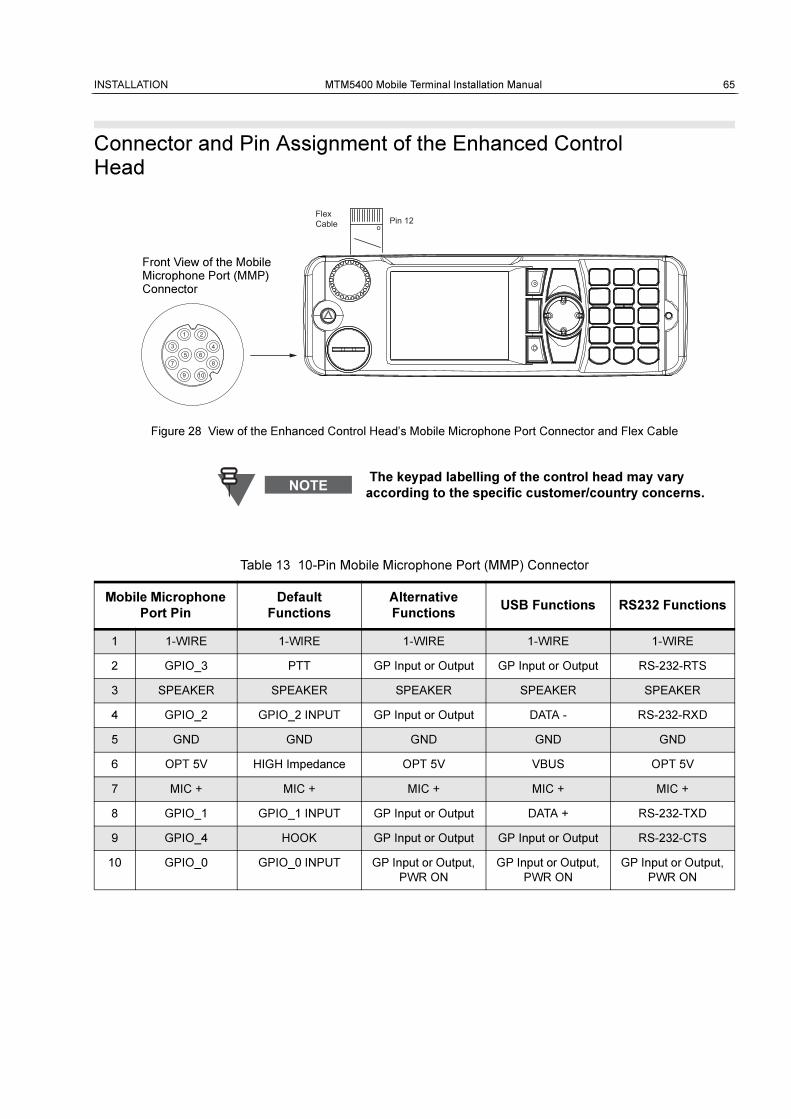
INSTALLATION MTM5400 Mobile Terminal Installation Manual 65
Connector and Pin Assignment of the Enhanced Control Head
Figure 28 View of the Enhanced Control Head’s Mobile Microphone Port Connector and Flex Cable
The keypad labelling of the control head may vary
according to the specific customer/country concerns.
Table 13 10-Pin Mobile Microphone Port (MMP) Connector
Mobile Microphone
Port Pin
Default
Functions
Alternative
FunctionsUSB Functions RS232 Functions
1 1-WIRE 1-WIRE 1-WIRE 1-WIRE 1-WIRE
2 GPIO_3 PTT GP Input or Output GP Input or Output RS-232-RTS
3 SPEAKER SPEAKER SPEAKER SPEAKER SPEAKER
4 GPIO_2 GPIO_2 INPUT GP Input or Output DATA - RS-232-RXD
5 GND GND GND GND GND
6 OPT 5V HIGH Impedance OPT 5V VBUS OPT 5V
7 MIC + MIC + MIC + MIC + MIC +
8 GPIO_1 GPIO_1 INPUT GP Input or Output DATA + RS-232-TXD
9 GPIO_4 HOOK GP Input or Output GP Input or Output RS-232-CTS
10 GPIO_0 GPIO_0 INPUT GP Input or Output,
PWR ON
GP Input or Output,
PWR ON
GP Input or Output,
PWR ON
oPin 12
FlexCable
21
3
7
9 10
8
45 6
Front View of the MobileMicrophone Port (MMP) Connector
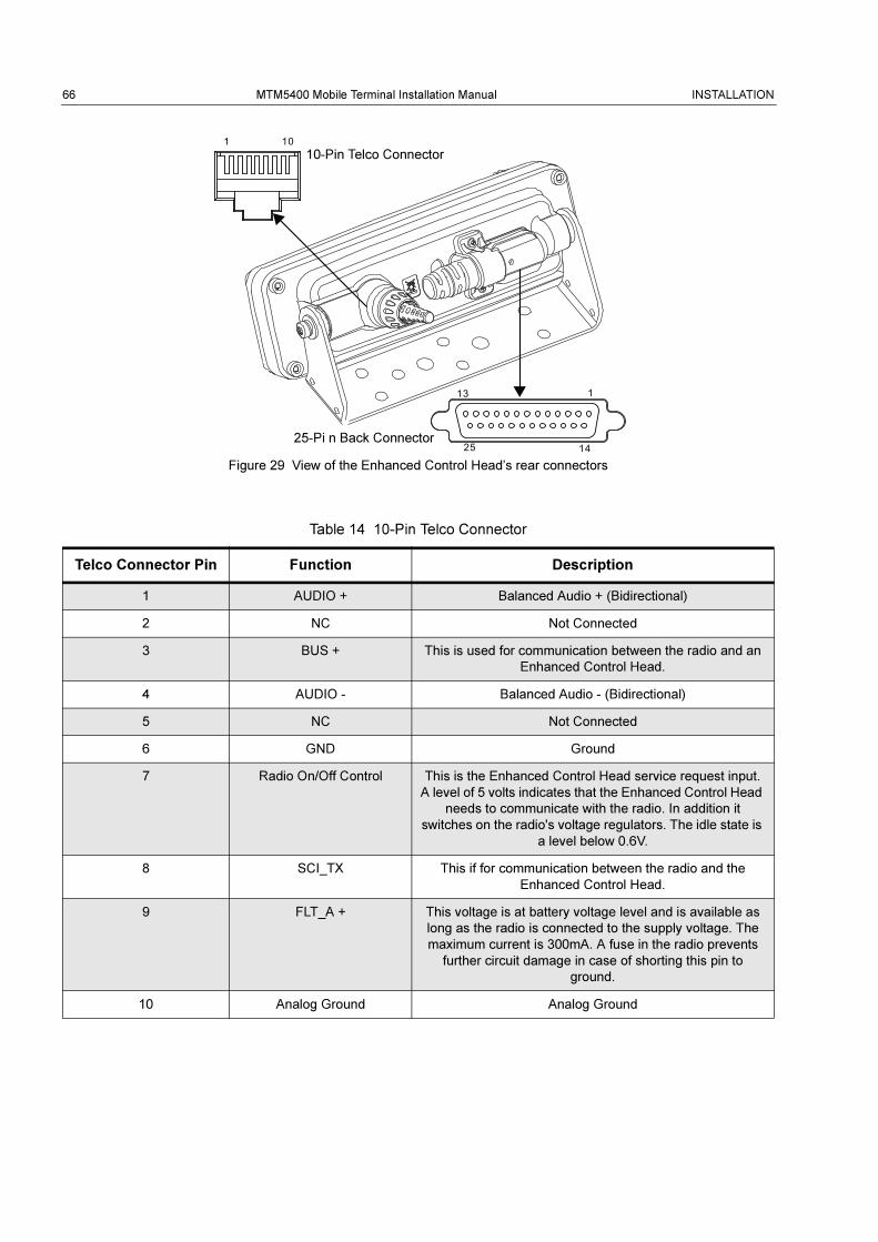
66 MTM5400 Mobile Terminal Installation Manual INSTALLATION
Figure 29 View of the Enhanced Control Head’s rear connectors
Table 14 10-Pin Telco Connector
Telco Connector Pin Function Description
1 AUDIO + Balanced Audio + (Bidirectional)
2 NC Not Connected
3 BUS + This is used for communication between the radio and an
Enhanced Control Head.
4 AUDIO - Balanced Audio - (Bidirectional)
5 NC Not Connected
6 GND Ground
7 Radio On/Off Control This is the Enhanced Control Head service request input.
A level of 5 volts indicates that the Enhanced Control Head
needs to communicate with the radio. In addition it
switches on the radio's voltage regulators. The idle state is
a level below 0.6V.
8 SCI_TX This if for communication between the radio and the
Enhanced Control Head.
9 FLT_A + This voltage is at battery voltage level and is available as
long as the radio is connected to the supply voltage. The
maximum current is 300mA. A fuse in the radio prevents
further circuit damage in case of shorting this pin to
ground.
10 Analog Ground Analog Ground
113
1 10
1425
10-Pin Telco Connector
25-Pi n Back Connector
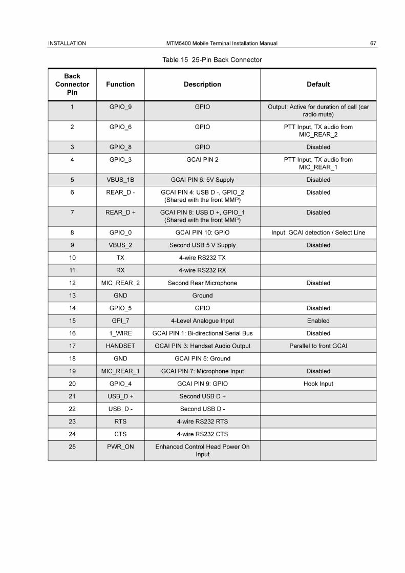
INSTALLATION MTM5400 Mobile Terminal Installation Manual 67
Table 15 25-Pin Back Connector
Back
Connector
Pin
Function Description Default
1 GPIO_9 GPIO Output: Active for duration of call (car
radio mute)
2 GPIO_6 GPIO PTT Input, TX audio from
MIC_REAR_2
3 GPIO_8 GPIO Disabled
4 GPIO_3 GCAI PIN 2 PTT Input, TX audio from
MIC_REAR_1
5 VBUS_1B GCAI PIN 6: 5V Supply Disabled
6 REAR_D - GCAI PIN 4: USB D -, GPIO_2
(Shared with the front MMP)
Disabled
7 REAR_D + GCAI PIN 8: USB D +, GPIO_1
(Shared with the front MMP)
Disabled
8 GPIO_0 GCAI PIN 10: GPIO Input: GCAI detection / Select Line
9 VBUS_2 Second USB 5 V Supply Disabled
10 TX 4-wire RS232 TX
11 RX 4-wire RS232 RX
12 MIC_REAR_2 Second Rear Microphone Disabled
13 GND Ground
14 GPIO_5 GPIO Disabled
15 GPI_7 4-Level Analogue Input Enabled
16 1_WIRE GCAI PIN 1: Bi-directional Serial Bus Disabled
17 HANDSET GCAI PIN 3: Handset Audio Output Parallel to front GCAI
18 GND GCAI PIN 5: Ground
19 MIC_REAR_1 GCAI PIN 7: Microphone Input Disabled
20 GPIO_4 GCAI PIN 9: GPIO Hook Input
21 USB_D + Second USB D +
22 USB_D - Second USB D -
23 RTS 4-wire RS232 RTS
24 CTS 4-wire RS232 CTS
25 PWR_ON Enhanced Control Head Power On
Input
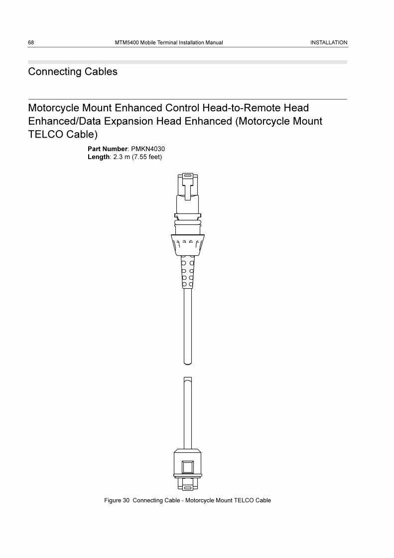
68 MTM5400 Mobile Terminal Installation Manual INSTALLATION
Connecting Cables
Motorcycle Mount Enhanced Control Head-to-Remote Head
Enhanced/Data Expansion Head Enhanced (Motorcycle Mount
TELCO Cable)
Part Number: PMKN4030
Length: 2.3 m (7.55 feet)
Figure 30 Connecting Cable - Motorcycle Mount TELCO Cable

INSTALLATION MTM5400 Mobile Terminal Installation Manual 69
Remote Mount Enhanced Control Head/Motorcycle Mount
Enhanced Control Head-to-Accessories (Accessories Expansion
Cable)
Part Number: PMKN4029
Figure 31 Connecting Cable - Accessories Expansion Cable
Table 16 Accessories Expansion Cable, Connector Pin Function
USB A JACK Signal subD 25 Pos
1 VBUS 9
2 D- 22
3 D+ 21
4 Ground 18
Mobile Microphone Port (MMP)
1 1_WIRE 16
2 GPIO_3 / OTG-ID / RTSc (PTT) 4
3 Speaker to Headset 17
4 GPIO_2 / D- / RxDc 6
5 GND (Ground) -
6 Opt_5V / VBUS 5
7 Mic+ 19
8 GPIO_1 / D+ / TxDc 7
9 GPIO_4 / CTSc / Keyfail (HOOK) 20
10 GPIO_0 / Pwr On 8
Customised Wire Color
BROWN / BLACK GPIO_9 1
ORANGE / BLACK GPIO_6 2
YELLOW / BLACK GPIO_8 3
LIGHT BLUE GPIO_2 6
TURQUOISE GPIO_1 7
GREEN / BLACK TX 10
BLUE / BLACK RX 11
GRAY / BLACK MIC_2 12
BLUE Ground 13
PINK / BLACK GPIO_5 14
BLACK / WHITE GPI_7 15
subD Connector
USB Connector
Mobile Microphone Port

70 MTM5400 Mobile Terminal Installation Manual INSTALLATION
BROWN / WHITE RTS 23
RED / WHITE CTS 24
ORANGE / WHITE Power On 25
RED / BLACK Headset 17
YELLOW / WHITE Ground -
USB A JACK Signal subD 25 Pos
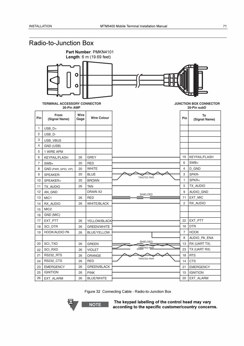
INSTALLATION MTM5400 Mobile Terminal Installation Manual 71
Radio-to-Junction Box
Part Number: PMKN4101
Length: 6 m (19.69 feet)
Figure 32 Connecting Cable - Radio-to-Junction Box
The keypad labelling of the control head may vary
according to the specific customer/country concerns.
TERMINAL ACCESSORY CONNECTOR26-Pin AMP
JUNCTION BOX CONNECTOR20-Pin subD
PinFrom
(Signal Name)Wire
Gage Wire Colour PinTo
(Signal Name)
19
6
4
3
1
5
9
11
2
22
16
7
8
13
23
18
14
21
15 IGNITION
20 EXT_ALARM
EMERGENCY
CTS
RTS
TX (UART RX)
RX (UART TX)
AUDIO_PA_ENA
HOOK
DTR
EXT_PTT
RX_AUDIO
EXT_MIC
AUDIO_GND
TX_AUDIO
SPKR+
SPKR-
D_GND
SWB+
KEYFAIL/FLASH
24 RS232_CTS RED26
26RS232_RTS21
1
EXT_PTT
SCI_RXD
SCI_TXD
HOOK/AUDIO PA
MIC2
SPEAKER+
TX_AUDIO
SPEAKER-
GND (PWR, GPIO, VIP)
SWB+
KEYFAIL/FLASH
1 WIRE APM
GND (USB)
USB_VBUS
USB_D+
USB_D-2
3
4
5
6
7
8
9
11
13
14
15
16
18
19
20
22
SCI_DTR
GND (MIC)
RX_AUDIO
MIC1
ORANGE
VIOLET
GREEN
BLUE/YELLOW
GREEN/WHITE
YELLOW/BLACK
GREY26
RED20
WHITE20
BLUE
20 BROWN
TAN26
26 RED
26 WHITE/BLACK
26
26
26
26
26
10
12
17
23
25
26
AN_GND
EMERGENCY
IGNITION
EXT_ALARM
26
26
26
GREEN/BLACK
PINK
BLUE/WHITE
DRAIN X2
20
SHIELDED
TWISTED PAIR
SHIELDED
TWISTED PAIR
TWISTED PAIR
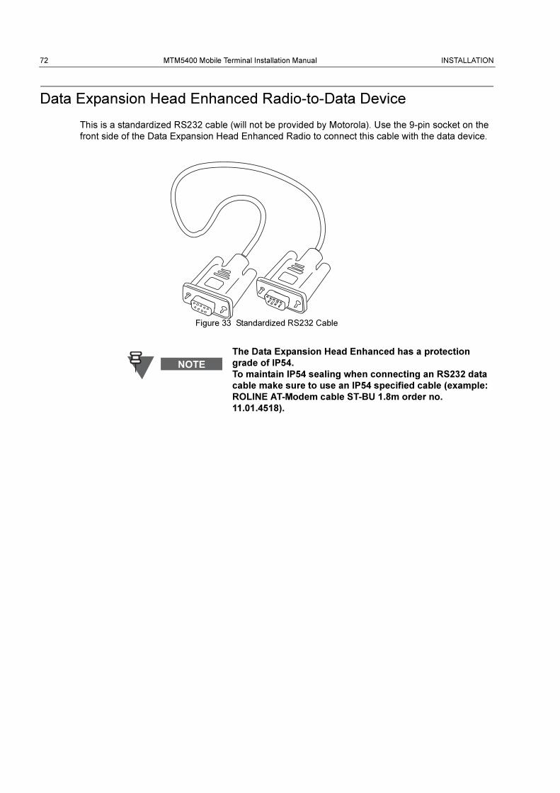
72 MTM5400 Mobile Terminal Installation Manual INSTALLATION
Data Expansion Head Enhanced Radio-to-Data Device
This is a standardized RS232 cable (will not be provided by Motorola). Use the 9-pin socket on the
front side of the Data Expansion Head Enhanced Radio to connect this cable with the data device.
Figure 33 Standardized RS232 Cable
The Data Expansion Head Enhanced has a protection
grade of IP54.
To maintain IP54 sealing when connecting an RS232 data
cable make sure to use an IP54 specified cable (example:
ROLINE AT-Modem cable ST-BU 1.8m order no.
11.01.4518).
INSTALLATION MTM5400 Mobile Terminal Installation Manual 73
Data Expansion Head Enhanced Radio-to-Fist Microphone
The GMKN4072 Connecting Cable replaces the existing coiled cord cable of the fist microphone
(Motorola P/N: GMMN4063).
Operation
The crimped wires of the cable have to be connected into the 26-pin Accessory Connector
(delivered with speaker RSN4002A) and than plugged into the 26-pin connector on the rear side of
the radio. The other end has a connector which fits into the fist microphone’s housing.
Making Connections
First connect the exposed four wires to the 26-pin Accessory Connector as shown in Figure 1 and
then plug the connector block into the 26-pin accessory socket on the rear side of the radio. The
connector block plugs into the 26-pin accessory connector (four outside pins do not connect).
Removing the Existing Coiled Cord Cable
1. Rotate the locking collar at the base of the microphone in a counterclockwise direction until it
stops.
2. Pull the cord out and away from the base of the of the microphone.
Install the new coiled cord GMKN4072 in a reverse order of removal.
Part Number: GMKN4072
Length: 65 cm (2.2 feet)
The GMKN4072 originally is terminated with a 20-pin
connector. Use the PMLN5072 accessory connector kit to re-
crimp it.
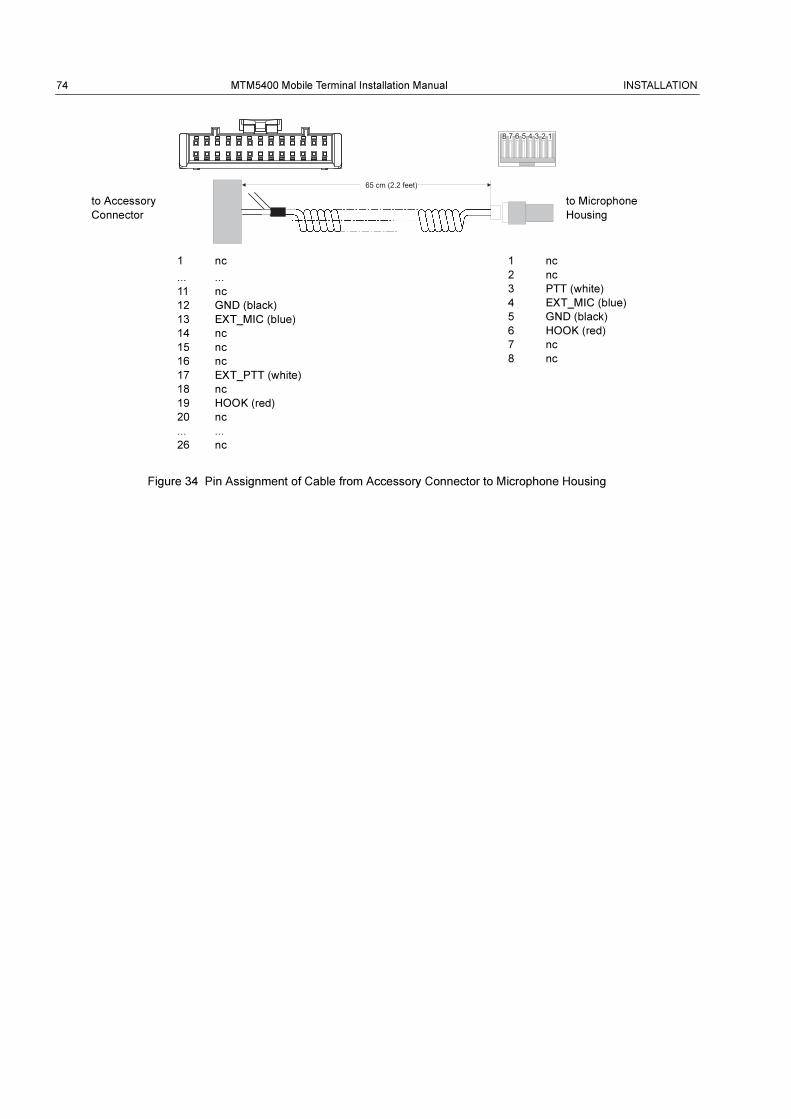
74 MTM5400 Mobile Terminal Installation Manual INSTALLATION
Figure 34 Pin Assignment of Cable from Accessory Connector to Microphone Housing
1 nc
... ...
11 nc
12 GND (black)
13 EXT_MIC (blue)
14 nc
15 nc
16 nc
17 EXT_PTT (white)
18 nc
19 HOOK (red)
20 nc
... ...
26 nc
1 nc
2 nc
3 PTT (white)
4 EXT_MIC (blue)
5 GND (black)
6 HOOK (red)
7 nc
8 nc
to Accessory
Connector
to Microphone
Housing
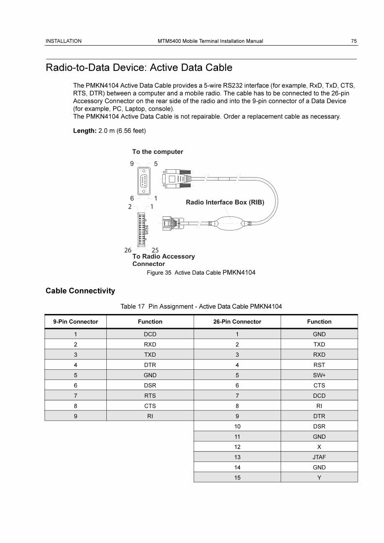
INSTALLATION MTM5400 Mobile Terminal Installation Manual 75
Radio-to-Data Device: Active Data Cable
The PMKN4104 Active Data Cable provides a 5-wire RS232 interface (for example, RxD, TxD, CTS,
RTS, DTR) between a computer and a mobile radio. The cable has to be connected to the 26-pin
Accessory Connector on the rear side of the radio and into the 9-pin connector of a Data Device
(for example, PC, Laptop, console).
The PMKN4104 Active Data Cable is not repairable. Order a replacement cable as necessary.
Length: 2.0 m (6.56 feet)
Figure 35 Active Data Cable PMKN4104
Cable Connectivity
Table 17 Pin Assignment - Active Data Cable PMKN4104
9-Pin Connector Function 26-Pin Connector Function
1 DCD 1 GND
2 RXD 2 TXD
3 TXD 3 RXD
4 DTR 4 RST
5 GND 5 SW+
6 DSR 6 CTS
7 RTS 7 DCD
8 CTS 8 RI
9 RI 9 DTR
10 DSR
11 GND
12 X
13 JTAF
14 GND
15 Y
2 1
26 25
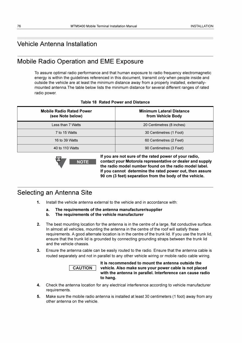
76 MTM5400 Mobile Terminal Installation Manual INSTALLATION
Vehicle Antenna Installation
Mobile Radio Operation and EME Exposure
To assure optimal radio performance and that human exposure to radio frequency electromagnetic
energy is within the guidelines referenced in this document, transmit only when people inside and
outside the vehicle are at least the minimum distance away from a properly installed, externally-
mounted antenna.The table below lists the minimum distance for several different ranges of rated
radio power.
Selecting an Antenna Site
1. Install the vehicle antenna external to the vehicle and in accordance with:
a. The requirements of the antenna manufacturer/supplier
b. The requirements of the vehicle manufacturer
2. The best mounting location for the antenna is in the centre of a large, flat conductive surface.
In almost all vehicles, mounting the antenna in the centre of the roof will satisfy these
requirements. A good alternate location is in the centre of the trunk lid. If you use the trunk lid,
ensure that the trunk lid is grounded by connecting grounding straps between the trunk lid
and the vehicle chassis.
3. Ensure the antenna cable can be easily routed to the radio. Ensure that the antenna cable is
routed separately and not in parallel to any other vehicle wiring or mobile radio cable wiring.
4. Check the antenna location for any electrical interference according to vehicle manufacturer
requirements.
5. Make sure the mobile radio antenna is installed at least 30 centimeters (1 foot) away from any
other antenna on the vehicle.
Table 18 Rated Power and Distance
Mobile Radio Rated Power
(see Note below)
Minimum Lateral Distance
from Vehicle Body
Less than 7 Watts 20 Centimetres (8 inches)
7 to 15 Watts 30 Centimetres (1 Foot)
16 to 39 Watts 60 Centimetres (2 Feet)
40 to 110 Watts 90 Centimetres (3 Feet)
If you are not sure of the rated power of your radio,
contact your Motorola representative or dealer and supply
the radio model number found on the radio model label.
If you cannot determine the rated power out, then assure
90 cm (3 feet) separation from the body of the vehicle.
It is recommended to mount the antenna outside the
vehicle. Also make sure your power cable is not placed
with the antenna in parallel. Interference can cause radio
to hang.
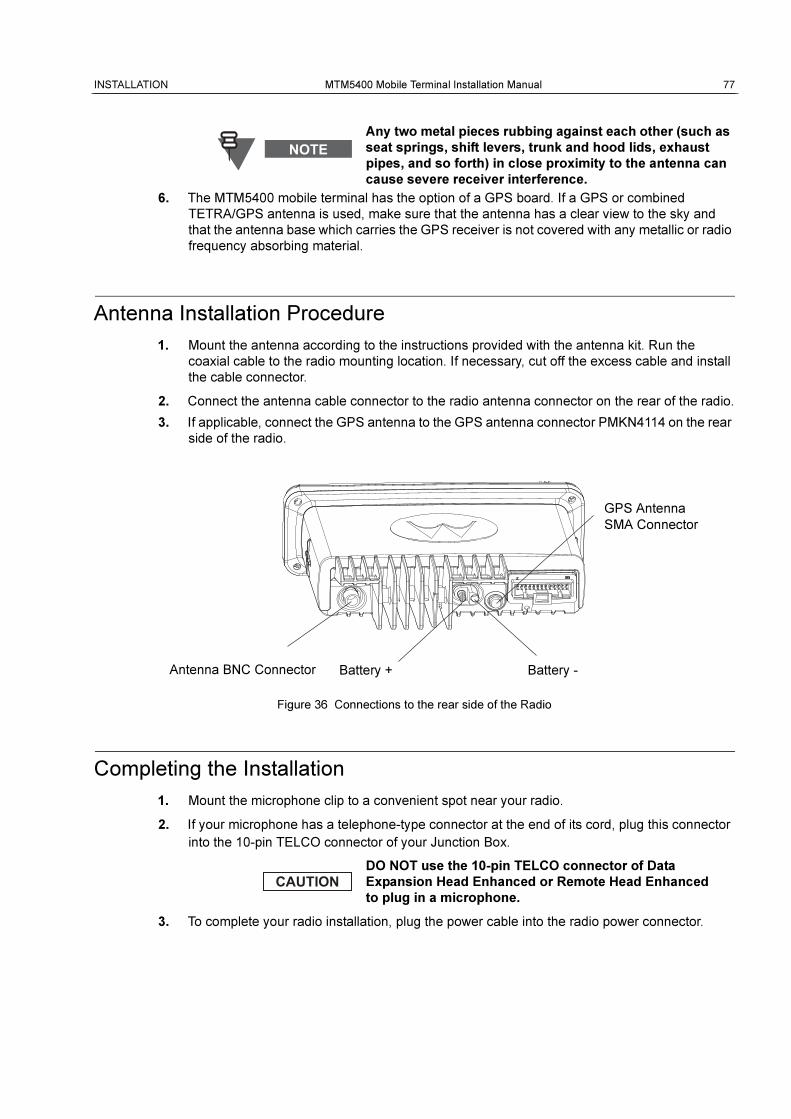
INSTALLATION MTM5400 Mobile Terminal Installation Manual 77
6. The MTM5400 mobile terminal has the option of a GPS board. If a GPS or combined
TETRA/GPS antenna is used, make sure that the antenna has a clear view to the sky and
that the antenna base which carries the GPS receiver is not covered with any metallic or radio
frequency absorbing material.
Antenna Installation Procedure
1. Mount the antenna according to the instructions provided with the antenna kit. Run the
coaxial cable to the radio mounting location. If necessary, cut off the excess cable and install
the cable connector.
2. Connect the antenna cable connector to the radio antenna connector on the rear of the radio.
3. If applicable, connect the GPS antenna to the GPS antenna connector PMKN4114 on the rear
side of the radio.
Figure 36 Connections to the rear side of the Radio
Completing the Installation
1. Mount the microphone clip to a convenient spot near your radio.
2. If your microphone has a telephone-type connector at the end of its cord, plug this connector
into the 10-pin TELCO connector of your Junction Box.
3. To complete your radio installation, plug the power cable into the radio power connector.
Any two metal pieces rubbing against each other (such as
seat springs, shift levers, trunk and hood lids, exhaust
pipes, and so forth) in close proximity to the antenna can
cause severe receiver interference.
DO NOT use the 10-pin TELCO connector of Data
Expansion Head Enhanced or Remote Head Enhanced
to plug in a microphone.
GPS Antenna
SMA Connector
Antenna BNC Connector Battery + Battery -
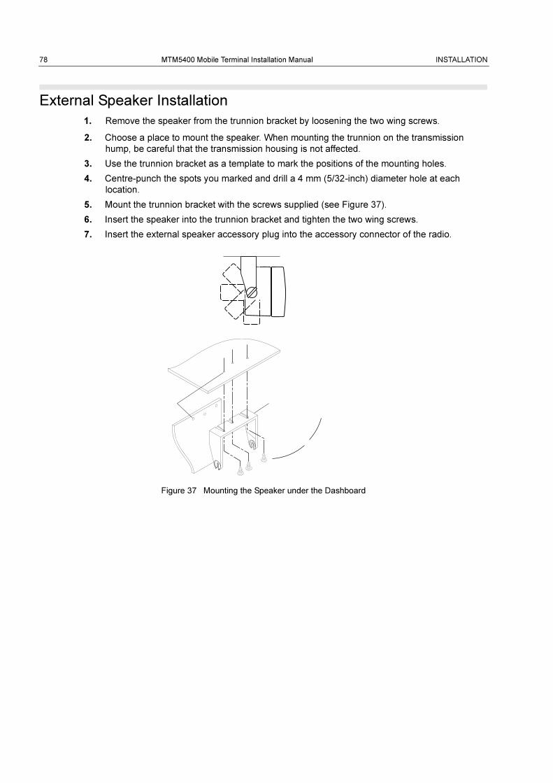
78 MTM5400 Mobile Terminal Installation Manual INSTALLATION
External Speaker Installation
1. Remove the speaker from the trunnion bracket by loosening the two wing screws.
2. Choose a place to mount the speaker. When mounting the trunnion on the transmission
hump, be careful that the transmission housing is not affected.
3. Use the trunnion bracket as a template to mark the positions of the mounting holes.
4. Centre-punch the spots you marked and drill a 4 mm (5/32-inch) diameter hole at each
location.
5. Mount the trunnion bracket with the screws supplied (see Figure 37).
6. Insert the speaker into the trunnion bracket and tighten the two wing screws.
7. Insert the external speaker accessory plug into the accessory connector of the radio.
Figure 37 Mounting the Speaker under the Dashboard
PRODUCT SPECIFIC INFORMATION MTM5400 Mobile Terminal Installation Manual 79
APPENDIX
Product Specific Informationfor Digital Terminals Type MT953C
This section gives the Service Personnel an overview about product specific notes. This is
necessary to take special precautions to avoid the introduction of hazards when operating,
installing, servicing or storing equipment. This terminal meets the applicable safety standards if it is
used as described. All operating and safety instructions are to be followed carefully.
Equipment Electrical Ratings
Rated Voltage: 12 Volt DC
Rated Voltage Range: 10.8 to 15.6 V DC
Rated Current:
MT953C (380-430 MHz): 4 Amps @ 10 Watts RF power
Please be aware when planning the installation that there is a current consumption of approx. 4.5A
during PTT and even 30mA when terminal is switched off.
Transmitter Frequency Range:
TMO: 380-430 MHz (MT953C)
DMO: 380-430 MHz (MT953C)
Receiver Frequency Range:
380-430 MHz (MT953C)
Normal Load Conditions
Rated RF Power: 10 Watts
Rated Audio Power: 10 Watts @ 4 Ohms; 6 Watts @ 8 Ohms
Antenna Impedance: 50 Ohms
Operating Temp. Range: -30 to +60°C
Operating Time: Continuous/Intermittent
In general, the terminal transmit and receive time
(operating cycle time) is determined by the
communication system. On overload, respectively on
extensive use beyond the systems specifications at high
ambient temperatures, the terminal is protected by its
thermal control, which cuts down the RF output power,
thus reducing the terminal coverage range.

80 MTM5400 Mobile Terminal Installation Manual PRODUCT SPECIFIC INFORMATION
Fuse Identification
In case of blown fuses during the installation replace ONLY with those of identical value.
Never insert ones of different values.
Fuse for Power Cable GKN6270/GKN6274: 10 A (Motorola Part Number: 6500139767)