Embed Size (px)
Citation preview

5400 Division Dr. | Fort Myers, FL 33905 239 690-9589 | Toll Free 877-425-4239 | FAX 239 690-1195
www.AXI-International.com
MTC
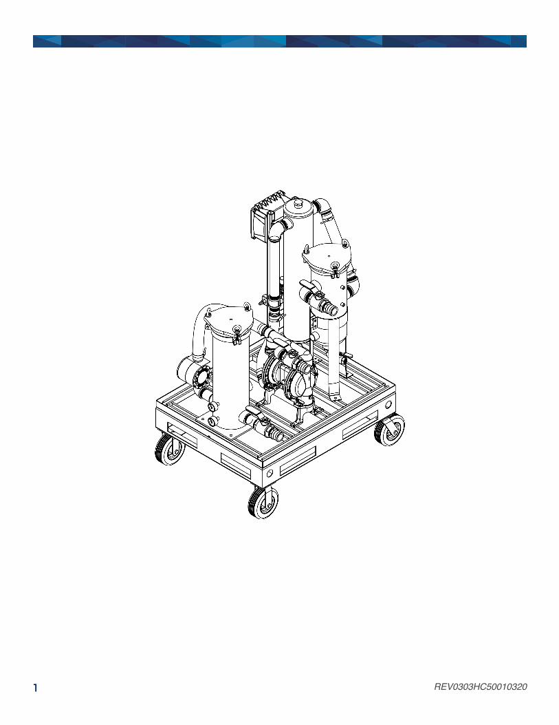
MTC HC-50 Instruction, Operating, & Maintenance Manual HIGH CAPACITY MOBILE FUEL POLISHING SYSTEM REV0303HC50010320
REV0303HC50010320 1
REV0303HC50010320 2
Table of Contents Table of Contents ................................................................................................................................................................ 2General Overview ................................................................................................................................................................ 3
MTC HC-50 Specifications ................................................................................................................................................. 3System Components ........................................................................................................................................................... 4
Control and Safety Devices ................................................................................................................................................ 4Pump/Motor ........................................................................................................................................................................ 4Primary Filter ...................................................................................................................................................................... 4Mechanical Water Separator .............................................................................................................................................. 4Fuel Conditioner ................................................................................................................................................................. 4Secondary Filter ................................................................................................................................................................. 4Plumbing ............................................................................................................................................................................ 4System Controller – If Applicable ....................................................................................................................................... 4
System Operation ................................................................................................................................................................ 5Setup Procedures .............................................................................................................................................................. 5Pump Operation – If Applicable ......................................................................................................................................... 5Phase 1 .............................................................................................................................................................................. 6Phase 2 .............................................................................................................................................................................. 6Phase 3 .............................................................................................................................................................................. 7Draining and Storing the System ....................................................................................................................................... 7Alarms – If Applicable ........................................................................................................................................................ 7
Primary Inspection .............................................................................................................................................................. 9Checklist ............................................................................................................................................................................. 9
Controller ............................................................................................................................................................................ 10Smart Filtration Controller (SFC-50) – If Applicable ......................................................................................................... 10
Commissioning/Initial Start-Up ........................................................................................................................................ 11Initial Test Procedures – If Applicable .............................................................................................................................. 11
Maintenance ....................................................................................................................................................................... 12Preventative Maintenance ................................................................................................................................................ 12Servicing the Water Separator ......................................................................................................................................... 12Servicing the Primary Filter .............................................................................................................................................. 12Servicing the Secondary Filter ......................................................................................................................................... 13Replacement Filter Chart ................................................................................................................................................. 13
Troubleshooting ................................................................................................................................................................ 14Symptom Troubleshooting Guide ..................................................................................................................................... 14
AXI International Limited Warranty .................................................................................................................................. 15Warranty Claim Procedure ............................................................................................................................................... 16
Technical Assistance and Ordering ................................................................................................................................. 17Replacement Filter Elements ........................................................................................................................................... 17System Identification ........................................................................................................................................................ 17

REV0303HC50010320 3
General Overview MTC HC-50 Specifications Nominal Flow Rate……………………………………………. 25 - 75 GPM/4,500 GPH (284 LPM/17,034 LPH)
Primary Filter………………...………………………………… Bag Filter Vessel, Liner Basket for use with 1-800μ Water Block
Water Separator……………………………………………….. FP-90 Mechanical Water Separator
Secondary Filter……………………………………………….. Cartridge Filter Vessel, 2-30μ Particulate, 5, 10, 15μ Water Block, or 10, 30μ Microglass
Fuel Conditioner……………………………………………….. LG-X 4000 Inline Magnetic Conditioner
Plumbing………………………………………………………... Black Iron
Inlet Port………………………………………………………… 2” Cam & Groove
Outlet Ports…….……………………….……………………… 2” Cam & Groove
Operating Temperature...……………………………………... 41 - 104° (5 - 40°C)
Power…..……………………………………………………….. Air Powered (25 -50 SCFM @ 90psi) – 1/2” Air Hose Connection*
Pump……………………………………………………………. Air-Driven Double-Diaphragm Pump
Suction Capability (Primed)…………………………………... 15ft. Vertical lift or 100ft. horizontal run (lines > 2”, primed)
Maximum Fluid Viscosity……………………………………… 5 cSt
Clear Suction Hose……….………………………………….. 2”, 25 ft. (7.6 m)
Discharge Hose….………………………………………….... 2”, 25 ft. (7.6 m)
Outline Dimensions………………………………..………….. ≈ 59” x 36” x 45” (150 x 91 x 114 cm) (H x W x D)
Weight…………………………………………………………… ≈ 630 lbs. (286 kg)
*Nominal flow rate varies based on the provided air power. !WARNING! This system is not meant for use with gasoline or any other flammable liquids having a flash point less than 100°F (37.8° C). Use with gasoline or any flammable liquids at a temperature exceeding their flash point presents an immediate explosion and fire hazard.

REV0303HC50010320 4
System Components
Control and Safety Devices • Vacuum & Pressure Gauges • Inlet and Outlet Ball Valves
o Inlet Ball Valve o Outlet Ball Valve (Discharge Port 1) o Outlet Ball Valve (Discharge Port 2)
Pump/Motor • Air-Driven Double-Diaphragm Pump
Primary Filter • Bag filter element (purchased separately) • Drain Valve
Mechanical Water Separator • Water Separator • Drain Valve
Fuel Conditioner • Inline Magnetic Fuel Conditioner
Secondary Filter • Cartridge filter element (purchased separately)
Plumbing • Black Iron
System Controller – If Applicable • SFC-50 Smart Filtration Controller
o Control Circuit Breakers (CB1, CB2) o Smart Filtration PLC with LCD Display o Pump Control Selector Switch (Manual/Off/Auto) o System Power Indicator Light o Pump Running Indicator Light o Alarm Indicator Light o Alarm Reset Push Button
• Vacuum & Pressure Switches • Solenoid Valve • Alarm Indication Stack Light • Water Detection Alarm Module
o Water Detection Sensor Probe • Remote Pendant Switch
REV0303HC50010320 5
System Operation !WARNING! The whole system must be properly grounded for operator safety. Note: It is recommended that only qualified, experienced personnel, familiar with this equipment, who have read and understood all the instructions in this manual should operate and maintain the system.
Setup Procedures To establish either fuel polishing mode, the user must attach both system hoses to the system in the proper configuration. The Intake/Suction Hose is clear and see-through while the Discharge Hose is black and opaque. Both hoses are equipped with quick disconnect cam & groove couplings.
1. First, attach the quick disconnect end of the clear Suction Hose to the Inlet Port of the system. 2. We highly recommend attaching a straight wand or pipe (cut at an angle) to the end of the Suction Hose in order
to reach the lowest part of the tank bottom. 3. The straight wand or pipe should be no less than the inner diameter of the Suction Hose.
Note: Never restrict the flow on the suction side of an MTC; e.g. by using a smaller ID hose or pipe attachment. This will lead to excessive pump load, noisy operation, and ultimately pump damage. Bypass Mode: In bypass mode, the fuel bypasses the system’s Secondary Filter only to be ran through the Primary Filter and Water Separator for the bulk removal of water, sludge, and particulate. To establish bypass mode:
1. Attached the quick disconnect end of the black Discharge Hose to Discharge Port 1 (located in the center of the system over the pump).
2. Before running the pump, ensure the Inlet Ball Valve and proper Discharge Ball Valve (Discharge Port 1) are in the open position.
3. Also, ensure the other Discharge Ball Valve (Discharge Port 2) and the Water Separator drain ball valve are in the closed position.
Fine Filtration Mode: In fine filtration mode, the fuel is run through the system’s high efficiency Secondary Filter element to remove free water and fine particulate as small as 1 micron. To establish fine filtration mode:
1. Attached the quick disconnect end of blue/black Discharge Hose to Discharge Port 2 (last port to the left of the pump).
2. Before running the pump, ensure the Inlet Ball Valve and proper Discharge Ball Valve (Discharge Port 2) are in the open position.
3. Also, ensure the other Discharge Ball Valve (Discharge Port 1) and the Water Separator drain ball valve are in the closed position.
Pump Operation – If Applicable Systems sold with the optional system controller feature two operational modes. To startup the system, you must first apply control power to unit. Place the control breakers for the System Controller in the “ON” position. Remote Mode: Place the Selector Switch in the “AUTO” position. To activate the pump simply press the Remote Pendant Switch. The pump will now run until either the Remote Pendant Switch is pressed again, the Selector Switch is placed in the “OFF” position, or a system alarm has been tripped.

REV0303HC50010320 6
Manual Mode: Place the Selector Switch in the “MANUAL” position. The pump will now run until either the Select Switch is placed in the “OFF” position or a system alarm has been tripped.
Phase 1 AXI recommends 3 phases to successfully polish a fuel tank. This will ensure all contaminates are removed and the fuel is in optimal condition. The goal of Phase One is to remove any free water and sludge from the bottom of the tank without mixing the water into an emulsified state within the fuel. The Pump will start pumping as long as the suction lift is not excessive. flow of the fuel can be observed in the see-through suction hose. Watch for a steady flow of fuel into the container. Note: To prevent pump damage, slowly start the pump with low air pressure values (20 – 30 PSI), especially if there is no fluid already in the pump. Once the complete system and hoses are full of fuel, you can begin to increase the air pressure to achieve the desired flow rate.
1. Setup up the system in the Bypass Mode configuration (see the Setup Procedures – Bypass Mode) and be sure to install a large micron (200µ or larger) filter bag in the Primary Filter vessel.
2. Place the Discharge Hose into a separate discharge waste container. 3. To remove as much of the free water and sludge as possible, the Suction Hose (with a straight wand or pipe
attachment) should be placed at the deepest part of the tank. 4. Turn on the Pump and be prepared to immediately switch it off once the fluid begins to fill the discharge container. 5. Inspect the discharged fluid and resume pumping until the bulk water and sludge have been removed from the
tank bottom and only fuel is primarily discharged from the return hose. 6. Switch off the Pump and drain all water and debris from the hose and the Water Separator (via the drain valve)
into an appropriate waste bucket or container.
Phase 2 The goal of Phase Two is to remove any additional free water, sludge, and large contaminants within the tank. This phase will further clean the fuel and should be a precursor to using the more expensive fine filters. It should be noted that meeting required cleanliness codes is typically not possible with Phase One and Two alone. Phase Two is simply used to extend the life of the Secondary Filter’s fine filter cartridges by removing the worst of the contaminants first.
1. Before turning on the Pump, ensure the system is still setup in the Bypass Mode configuration (see the Setup Procedures – Bypass Mode).
2. Remove the Discharge Hose from the waste container and place it into the tank. 3. If possible, ensure the Suction and Discharge Hoses are placed as far apart as possible.
Note: In many cases, both hoses may have to be inserted through the same tank opening.
4. After verifying that both hoses are properly placed in the fuel tank and that the ball valves on the system are in the correct position, switch on the pump and watch the clear suction hose for fuel flow.
5. While polishing, it is good practice to watch the fuel flow and regularly stop the pump to check for buildup of free water and sludge in the Water Separator (see Maintenance – Servicing the Water Separator).
Note: For systems equipped with a smart filtration controller, the High Water alarm will be triggered and indicated on the system controller to automatically notify you of when the Water Separator needs to be drained of water.
6. It is also good practice to monitor the Vacuum Gauges to know when to service a clogged Primary Filter element in order to avoid flow restriction (see Maintenance – Servicing the Primary Filter).

REV0303HC50010320 7
Note: For systems equipped with a smart filtration controller, the High Vacuum alarm will be triggered and indicated on the system controller to automatically notify you of when to replace the Primary Filter’s filter bag.
7. The system should be kept running until clean fuel samples can be drained from the Water Separator. Once this is achieved, switch off the pump to prepare for the final polishing phase.
Phase 3 Phase Three is the most important phase in meeting specific cleanliness codes. Unlike the Primary Filter and Water Separator, the Secondary Filter’s fine filter cartridges typically uses an absolute rated media. Absolute filters have a very high efficiency and will ensure that fuel leaving the system is clean to specification.
1. Before turning on the Pump, ensure the system is setup in the Fine Filtration Mode configuration (see the Setup Procedures – Fine Filtration Mode) and be sure to install both Primary and Secondary Filters with a bag and cartridge filter respectively.
2. After verifying that both hoses are properly placed in the fuel tank and that the ball valves on the system are in the correct position, start the pump and monitor the Pressure Gauges in addition to the Vacuum Gauges to also know when the Secondary Filter need servicing (see Maintenance – Servicing the Secondary Filter).
Note: For systems equipped with a smart filtration controller, the High Pressure alarm will be triggered and indicated on the system controller to automatically notify you of when to replace the Secondary Filter’s filter cartridge.
Draining and Storing the System 1. Reduce the flow rate and run the pump with low air pressure values (20 – 30 PSI) 2. Remove the suction hose from the tank while the pump is still running and wait until system is purged of any
remaining fuel. !WARNING! DO NOT operate the vane pump dry for longer than 60 seconds to avoid significant mechanical damage.
3. Turn off the pump and place an appropriate container under the Water Separator and Discharge Port 1. 4. Open their respective ball valve and use the air purge valve on top of the separator to make sure all of the fluid
can be drained from the system.
Alarms – If Applicable Systems sold with the optional system controller feature the following alarms:
• High Water (pump shutdown, alarm indication) o Activated when the water trips the Water Detection Alarm Module via the Water Detection Sensor Probe
located on the Mechanical Water Separator. The system will go into an alarm state and the system’s solenoid valve will stop air flow to pump until the Water Separator has been serviced (see Maintenance – Servicing the Water Separator) and the alarm has been cleared via the Alarm Reset Button on the system controller.
• High Vacuum (pump shutdown, alarm indication) o Activated when the Vacuum Switch, placed on the suction side of the pump, detects a reading above the
pre-established set point. The system will go into an alarm state and the system’s solenoid valve will stop air flow to pump until the Primary Filter has been serviced (see Maintenance – Servicing the Primary Filter) and the alarm has been cleared via the Alarm Reset Button on the system controller.
REV0303HC50010320 8
• High Pressure (pump shutdown, alarm indication) o Activated when the Pressure Switch, placed on the discharge side of the pump, detects a reading above
the pre-established set point. The system will go into an alarm state and the system’s solenoid valve will stop air flow to pump until the Secondary Filter has been serviced (see Maintenance – Servicing the Secondary Filter) and the alarm has been cleared via the Alarm Reset Button on the system controller.

REV0303HC50010320 9
Primary Inspection Upon arrival, the system and accessories must be visually inspected before installation. Improper handling during shipping may cause physical or electrical problems. Immediately report or note any damages to the shipper.
Checklist � If the packing crate shows signs of damage inspect the system for damage. � Check the entire system for damage that could indicate internal mechanical or electrical problems. � Check pump/motor hardware and all plumbing connections for tightness. � Check all electrical terminals and connections for tightness.

REV0303HC50010320 10
Controller
Smart Filtration Controller (SFC-50) – If Applicable The System Controller is used to both operate the system and indicate/reset system alarms should they be triggered. Pump Control Selector Switch (Manual/Off/Auto) Turns the system on to either “Manual” or “Remote” operational modes (See Operation – System Controller) Pump Running Indicator Light Indicated the system pump is running System Power Indicator Light Indicates the system has power Alarm Indicator Light Indicates the labeled alarm (displayed on the Smart Filtration PLC) has been tripped Alarm Reset Push Button Resets the system alarm(s) once the alarm state(s) have been addressed

REV0303HC50010320 11
Commissioning/Initial Start-Up
Initial Test Procedures – If Applicable With breakers and power turned on, and pump running, check all alarms for proper operation:
• High Water Alarm - Jump the Water Detection Sensor Probes by placing a conductor across the two horizontal contacts. The pump should turn off after 10 seconds and “High Water” alarm should be indicated on the System Controller. Remove the metal and reset the alarm by pushing the Alarm Reset button on the System Controller.
• High Vacuum Alarm - Slowly, partially close Inlet Ball Valve. At 16” HG, the pump should turn off and the “High Vacuum” alarm should be indicated on the System Controller. Open the Inlet Ball Valve again. Reset the alarm by pushing the Alarm Reset button on the System Controller.
• High Pressure Alarm - Slowly, partially close Outlet Ball Valve. At 22 PSI, the pump should turn off (after a delay of about 1 second) and the “High Pressure” alarm should be indicated on the System Controller. Open the Outlet Ball Valve again. Reset the alarm by pushing the Alarm Reset button on the System Controller.
Note: If any of the above described alarm test procedures fail or if any alarm trip value deviates, immediately contact AXI International.

REV0303HC50010320 12
Maintenance The system should be visually inspected and tested a minimum of every six (6) months according to the procedure below during light duty cycles. Monthly inspections are recommended for systems that are being used in excess of an average of eight (8) hours a day and five (5) days a week.
Preventative Maintenance Prior to performing the maintenance procedure ensure that:
1. All sources of power are isolated from the unit
Note: Proceed only after this has been verified and properly tagged.
2. Check system and all parts for corrosion and rust. 3. Check bolts on the pump/motor hardware for tightness, as pump/motor hardware can loosen after normal
operation for extended durations of time, due to vibration. 4. Check all plumbing joints for leaks, tighten fittings and joints as necessary. 5. Inspect all filter vessel and elements.
Servicing the Water Separator It is recommended the Water Separator be periodically serviced to prevent excessive water buildup. Draining of Water Separator:
1. Ensure the system’s pump is turned off. 2. Close the inlet and outlet ball valves. 3. Place an appropriate container under the drain valve. 4. Remove the top plug to allow air in and fuel to flow out. 5. Open the drain valve and allow the water and sludge to drain. 6. Close the drain valve when you begin observing clean fuel.
Note: Disposal of fuel, associated waste, and filters must be in accordance with all applicable federal, state, and local rules, laws, standards, and regulations. !WARNING!: Some fuels may have been treated with biocides. Biocides are extremely toxic and may enter the body through the skin. It is recommended to use adequate protection and proper precautions if the fuel at-hand contains biocide type products.
Servicing the Primary Filter A clogged filter element restricts the flow of fuel, resulting in the vacuum gauges indicating a pressure drop. A differential vacuum reading of 15” HG between the two vacuum gauges will indicate when a filter change should be made on the Primary Filter. Changing the Bag Filter:
1. Ensure the system’s pump is turned off. 2. Close the inlet and outlet ball valves. 3. Release all pressure in system by carefully opening the air vent valves. 4. Loosen the vessel’s lid screws and open the lid 5. Remove the old filter element and check the inner housing for any debris or sludge. 6. Place the new filter element into the housing. 7. Apply a film of lubricating oil to the lid gasket. Replace the O-Ring if worn or damaged. 8. Tighten the lid screws evenly to ensure the lid is fully seated on the O-Ring gasket. 9. Open the inlet and outlet ball valves.

REV0303HC50010320 13
10. Check for leaks when re-starting and pressurizing the system.
Servicing the Secondary Filter A clogged filter element restricts the flow of fuel, resulting in the system’s pressure gauges indicating a pressure spike. A differential pressure drop of 20 - 25 PSI between the two pressure gauges will indicate when a filter change should be made on the Secondary Filter. Changing the fine filter cartridge:
1. Ensure the system’s pump is turned off. 2. Close the inlet and outlet ball valves. 3. Release all pressure in system by carefully opening the air vent valves. 4. Loosen the vessel’s lid screws and open the lid 5. Remove the old filter element and check the inner housing for any debris or sludge. 6. Place the new filter element into the housing. 7. Apply a film of lubricating oil to the lid gasket. Replace the O-Ring if worn or damaged. 8. Tighten the lid screws evenly to ensure the lid is fully seated on the O-Ring gasket. 9. Open the inlet and outlet ball valves. 10. Check for leaks when re-starting and pressurizing the system.
Replacement Filter Chart
MTC HC SERIES FILTERS All Filters are absolute, unless otherwise noted | wb: waterblock | SS: Stainless Steel Screen
Cartridge Filters
2µ 10µ 10µ WB 30µ 30µ WB 3µ Micro-glass 7µ MICRO-Glass 10µ MICRO-Glass
MTC HC-50 618-2-W 618-10-W WA618-30-W 618-30-W WA618-30-W G618-3-SR G618-7-SR G618-10-SR MTC HC-90 618-2-W 618-10-W WA618-30-W 618-30-W WA618-30-W G618-3-SR G618-7-SR G618-10-SR
MTC HC-150 618-2-W 618-10-W WA618-30-W 618-30-W WA618-30-W G618-3-SR G618-7-SR G618-10-SR
MTC HC-300 618-2-W 618-10-W WA618-30-W 618-30-W WA618-30-W G618-3-SR G618-7-SR G618-10-SR
Bag Filters
1µ 5µ 10µ 25µ 75µ 250µ 800µ
MTC Hc-50 PFB-30-1 PFB-30-5 PFB-30-10 PFB-30-25 PFB-30-75 PFB-30-250 PFB-30-800
MTC HC-90 PFB-30-1 PFB-30-5 PFB-30-10 PFB-30-25 PFB-30-75 PFB-30-250 PFB-30-800
MTC HC-150 PFB-150-1 PFB-150-5 PFB-150-10 PFB-150-25 PFB-150-75 PFB-150-250 PFB-150-800
MTC HC-300 PFB-150-1 PFB-150-5 PFB-150-10 PFB-150-25 PFB-150-75 PFB-150-250 PFB-150-800

REV0303HC50010320 14
Troubleshooting
Symptom Troubleshooting Guide No fuel delivery
1. Pump does not run 2. Pump is not primed 3. Fuel supply or return line blocked 4. Primary filter is clogged 5. Excessive lift 6. Air leak in fuel supply to pump 7. Intake or outlet valve closed 8. Liquid too viscous
Insufficient fuel delivered
1. Air leak at inlet 2. Defective pressure relief 3. Excessive lift 4. Pump worn 5. Flow restriction in hose/plumbing 6. Liquid too viscous 7. Filter plugged
Rapid pump wear
1. Pipe strain on pump causing bind 2. Worn pump/motor coupler 3. Pump has been run dry or with insufficient fuel 4. Plumbing on inlet side not appropriately
dimensioned Vacuum differential is more than 15”HG or the “High Vacuum” alarm is triggered with clean or new filter element installed
1. Restriction on inlet side too high 2. Lift too high 3. Inlet ball valve not fully open 4. Suction line/Water Separator/Primary Filter
clogged Pressure differential is more than 20 – 25 PSI or the “High Pressure” alarm is triggered with clean or new filter element installed
1. Restriction on discharge side too high 2. Head (lift) on discharge side too high 3. Check filter for water saturation (WB only) 4. Outlet ball valve not fully open 5. Secondary Filter/Fuel Conditioner/Discharge line
clogged
Pump requires too much power 1. Air in plumbing lines 2. Liquid too viscous 3. Bent pump shaft, binding rotor
Noisy operation
1. Insufficient fuel supply 2. Air leaks in the inlet pipe 3. Air or gas in fuel on the suction side 4. Excessive pump load (differential vacuum >
15”HG) Pump requires frequent re-priming
1. Pump cavitation 2. Plumbing air leaks 3. Lift too high 4. Leaking pump seal
Motor does not turn or turns intermittently
1. Control power not available 2. Motor thermal overload condition 3. Pump failed and seized 4. Motor failure
Pump leaks fuel
1. Loose pump plumbing fittings 2. Worn pump shaft seal 3. Pump pressure relief valve failure 4. Fuel leak elsewhere and fuel dripping or running
towards the pump 5. Excessive head from overhead storage tank 6. Worn pump O-rings or seals

REV0303HC50010320 15
AXI International Limited Warranty AXI International makes every effort to assure that its products meet high quality and durability standards and expressly warrants the products described herein against defects in material and workmanship for a period of one (1) year from the date of purchase. This warranty is not intended to supplant normal inspection, care and service of the products covered by the user, and shall not obligate AXI International to provide free service during the warranty period to correct breakage, maladjustment, or other difficulties arising out of abuse, misuse, or improper care and maintenance of such products. Our express warranty is subject to the following terms and conditions: This warranty shall only extend to and is only for the benefit of original purchaser(s), or end customer(s) who use the products covered hereby and subject to the terms and conditions herein. This warranty is not an on-site warranty. Travel requests will be at the discretion of AXI International. Defective systems and ancillary products will require a return authorization number and shipping to AXI International’s factory in Fort Myers, FL. Any warranty claim received by AXI International after one (1) year from the date of purchase will not be honored even if it is claimed that the defect occurred prior to one (1) year from the date of purchase. Claims outside of this one (1) year period, and for claims not listed within, payment, repair, or service will be awarded at the sole and exclusive discretion of AXI International. This Warranty shall NOT apply to the following:
1. Damage or deterioration caused by normal wear and tear. 2. Failures caused by any external cause or act of God, such as accident, collision, theft, vandalism, riots, wars, re,
freezing, lightning, earthquakes, windstorms, hail, volcanic eruptions, floods, tornados or hurricanes. 3. Failures due to alterations, adjustments, unauthorized changes to the product(s), neglect or improper storage,
repair and/or maintenance. 4. Failures due to abuse or application of the product(s) for uses other than for which it/they are designed or
intended by AXI International, including but not limited to, improper installation or location in a harsh, corrosive or saltwater environment.
5. Failures resulting from attachments, accessory items, and parts not sold by AXI International. 6. Repairs by any party other than those authorized by AXI International. 7. Failures resulting from user’s delay in making the product available for inspection by AXI International after
notifying AXI International of a potential product problem. 8. Cosmetic damage, discoloration, rusting, corrosion or scratches from applied paint. 9. Replacement of consumables such as, but not limited to, fuses, lamps, filters, etc. 10. Additional expenses for repair after normal business hours, i.e., overtime or holiday labor rates. 11. Expenses for rental of equipment during downtime and/or performance of warranty repairs. 12. Expenses related to investigating performance complaints and/or troubleshooting where no manufacturing defect
is found. In addition to the limitations above, this warranty shall not apply to products (1) which have been tampered with, altered or repaired by anyone other than AXI International without the express prior written consent of AXI International (2) which have been installed improperly or subject to misuse, abuse, accident, negligence of others, improper operation or maintenance, neglect or modification, or (3) which have had the serial number altered, defaced or removed. The liability of AXI International under this warranty is limited to the repair or replacement of the defective product. AXI International assumes NO LIABILITY for labor charges or other costs incurred by any purchaser incidental to the service, adjustment, repair, return, removal or replacement of products. AXI INTERNATIONAL ASSUMES NO LIABILITY FOR ANY GENERAL, SPECIAL, INCIDENTAL, CONSEQUENTIAL, CONTINGENT OR OTHER DAMAGES UNDER ANY WARRANTY, EXPRESS OR IMPLIED, OF MERCHANTABILITY, FITNESS FOR A PARTICULAR PURPOSE OR OTHERWISE, WITH THE RESPECT TO THE PRODUCTS COVERED BY THIS WARRANTY POLICY, EXCEPT AS EXPRESSLY PROVIDED FOR HEREIN. AXI INTERNATIONAL ASSUMES NO LIABILITY FOR ANY GENERAL, SPECIAL, INCIDENTAL, CONSEQUENTIAL, CONTINGENT OR OTHER DAMAGES EVEN IF SUCH DAMAGES ARE A DIRECT RESULT OF AXI INTERNATIONAL’S NEGLIGENCE. NO EMPLOYEE, AGENT, REPRESENTATIVE OR DISTRIBUTOR IS AUTHORIZED TO MAKE ANY WARRANTY ON BEHALF OF AXI INTERNATIONAL OTHER THAN THE EXPRESS WARRANTY PROVIDED FOR HEREIN.

REV0303HC50010320 16
AXI International reserves the right at any time to make changes in the design, material, function and specifications of its products. Any such changes shall not obligate AXI International to make similar changes in such products that were previously manufactured. To the fullest extent permitted by law, any claims against AXI International are limited to the remedies as expressly set forth in this warranty and any other further claims, such as but not limited to, compensation for any damage incurred other than to the AXI International product, are hereby excluded.
Warranty Claim Procedure To make a claim under this warranty, please call AXI International at +1-239-690-9589 or 1-877-425-4239, and provide: Name and location where unit was purchased, the date and receipt of purchase, model number, serial number, and a detailed explanation of the problem you are experiencing. The Customer Service Representative may, at the discretion of AXI International, arrange for a Field Engineer to inspect your system. If the inspection reveals a defect covered by its limited warranty, AXI International will either repair or replace the defective parts or products. AXI International assumes no liability, if upon inspection, AXI International or its representative determines that there is no defect or that the damage to the system resulted from causes not within the scope of this limited warranty and customer shall be responsible standard rates incurred by AXI International, as established from time to time by AXI International. For service and sales, please contact AXI International: AXI International | 5400 Division Drive Fort Myers, FL 33905 Tel: +1-239-690-9589 | Toll Free: +1-877-425-4239 | Fax: +1-239-690-1195 Email: [email protected] | Internet: www.axi-international.com

REV0303HC50010320 17
Technical Assistance and Ordering Please write, fax, email or call: AXI International 5400 Division Drive Fort Myers, FL 33905 Tel: +1-239-690-9589 Fax: +1-239-690-1195 Email: [email protected] Internet: www.axi-international.com Please provide the following information: Serial Number of your system, the required part numbers and quantity. The drawings/parts list included in this manual are the most accurate source of part numbers.
Replacement Filter Elements Primary Filter: PFB-30-1 - 1μ Bag Filter PFB-30-5 - 5μ Bag Filter PFB-30-10 - 10μ Bag Filter PFB-30-25 - 25μ Bag Filter PFB-30-75 - 75μ Bag Filter PFB-30-250 - 250μ Bag Filter PFB-30-800 - 800μ Bag Filter Secondary Filters: 618-2-W - 2μ Filter Cartridge 618-10-W - 10μ Filter Cartridge 618-30-W - 30μ Filter Cartridge WA618-10-W - 10μ Filter Cartridge (Water Block) WA618-30-W - 30μ Filter Cartridge (Water Block) G618-3-SR - 3μ Microglass Absolute Filter Cartridge G618-7-SR - 7μ Microglass Absolute Filter Cartridge G618-10-SR - 10μ Microglass Absolute Filter Cartridge
System Identification Serial Number: ___________________________________________ (e.g. B090010-HC50) Inspected By: ____________________________________________ Date:____________