Embed Size (px)
Citation preview
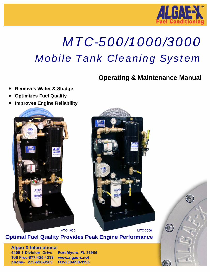
MTC-500/1000/3000 Mobile Tank Cleaning System
Operating & Maintenance Manual
• Removes Water & Sludge • Optimizes Fuel Quality • Improves Engine Reliability
Optimal Fuel Quality Provides Peak Engine Performance MTC-3000 MTC-1000
MTC-350 / MTC-500 / MTC-1000 / MTC-3000 ALGAE-X® 2006-Rev. C 2
INSTALLATION, OPERATING AND MAINTENANCE MANUAL
CONTENT INITIAL INSPECTION................................................................................................................ 6 OVERVIEW - MOBILE TANK CLEANING SYSTEM ................................................................. 6 TANK CLEANING - WHY, WHERE AND HOW......................................................................... 7 GENERAL TANK CLEANING PROCEDURE............................................................................ 7 AFC-705 FUEL CATALYST....................................................................................................... 8 AFTER CLEANING THE TANKS .............................................................................................. 8 TANK CLEANING “101” ........................................................................................................... 9 PREPARATIONS ...................................................................................................................... 9 START–UP PROCEDURE........................................................................................................ 9
Priming the System................................................................................................................ 9 OPERATING PROCEDURE – STEP BY STEP ...................................................................... 10 WE ARE NOW READY FOR................................................................................................... 10 FILTERS – MTC 500 / 1000 / 3000 ......................................................................................... 12
Changing Filters................................................................................................................... 12 FILTERS – MTC 350 ............................................................................................................... 13
Servicing and Back-flushing the MTC-350 filter: .................................................................. 13 MTC MAINTENANCE.............................................................................................................. 14
Draining and Storing the System ......................................................................................... 14 Pump Strainer / Y-Strainer (MTC-500)................................................................................. 14 Fuel / Oil Separator / Coalescer........................................................................................... 14 Pump.................................................................................................................................... 14 LG-X Fuel Conditioner ......................................................................................................... 14 Suction and Discharge hoses .............................................................................................. 14
SAFETY NOTES ..................................................................................................................... 15 TROUBLESHOOTING............................................................................................................. 15 TANK CLEANING SYSTEMS WARRANTY ............................................................................ 17 TECHNICAL ASSISTANCE AND ORDERING........................................................................ 18
Replacement filter elements................................................................................................. 18 MTC-350 / 500 / 1000 / 3000 SYSTEM IDENTIFICATION.................................................. 18
MTC-350 / MTC-500 / MTC-1000 / MTC-3000 ALGAE-X® 2006-Rev. C 3
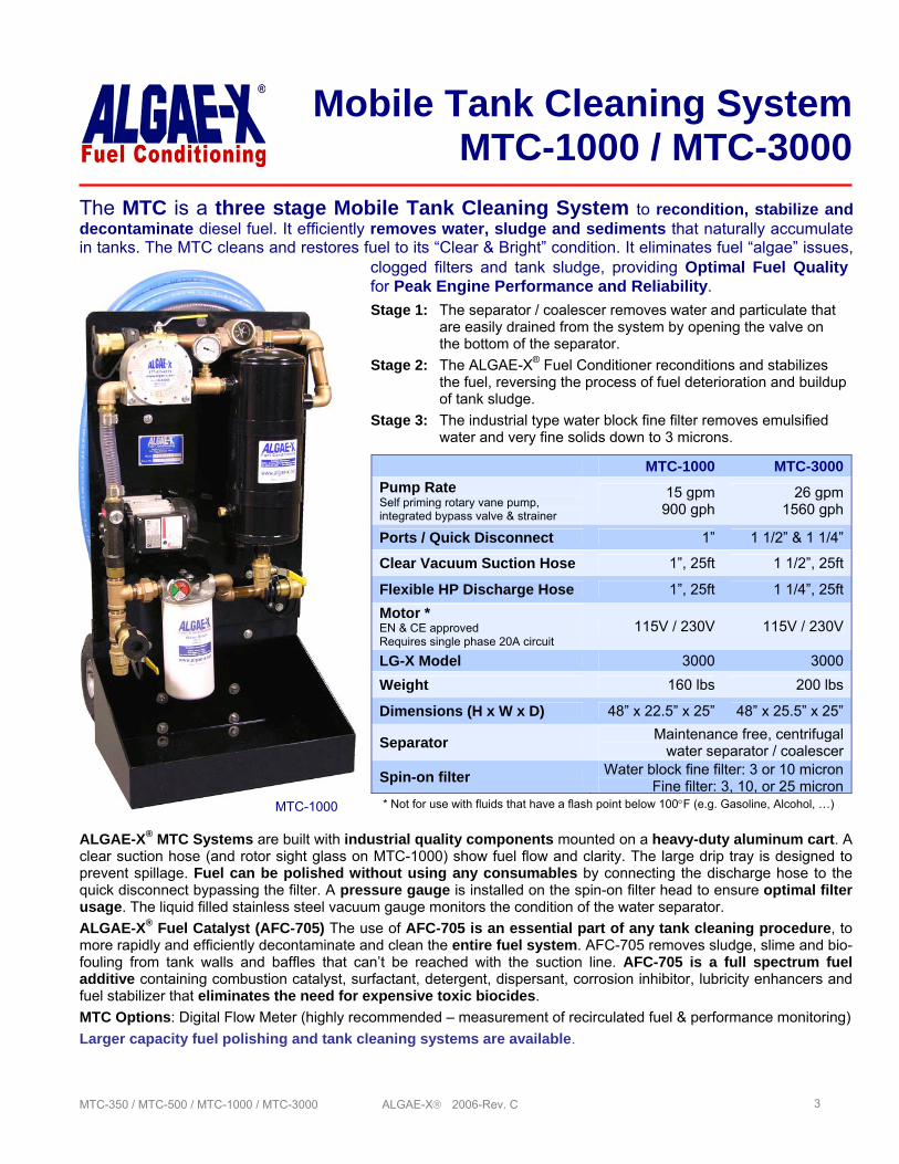
ALGAE-X® MTC Systems are built with industrial quality components mounted on a heavy-duty aluminum cart. A clear suction hose (and rotor sight glass on MTC-1000) show fuel flow and clarity. The large drip tray is designed to prevent spillage. Fuel can be polished without using any consumables by connecting the discharge hose to the quick disconnect bypassing the filter. A pressure gauge is installed on the spin-on filter head to ensure optimal filter usage. The liquid filled stainless steel vacuum gauge monitors the condition of the water separator. ALGAE-X® Fuel Catalyst (AFC-705) The use of AFC-705 is an essential part of any tank cleaning procedure, to more rapidly and efficiently decontaminate and clean the entire fuel system. AFC-705 removes sludge, slime and bio-fouling from tank walls and baffles that can’t be reached with the suction line. AFC-705 is a full spectrum fuel additive containing combustion catalyst, surfactant, detergent, dispersant, corrosion inhibitor, lubricity enhancers and fuel stabilizer that eliminates the need for expensive toxic biocides. MTC Options: Digital Flow Meter (highly recommended – measurement of recirculated fuel & performance monitoring)
Larger capacity fuel polishing and tank cleaning systems are available.
clogged filters and tank sludge, providing Optimal Fuel Quality for Peak Engine Performance and Reliability.
Mobile Tank Cleaning SystemMTC-1000 / MTC-3000
Stage 1: The separator / coalescer removes water and particulate that are easily drained from the system by opening the valve on the bottom of the separator.
Stage 2: The ALGAE-X® Fuel Conditioner reconditions and stabilizes the fuel, reversing the process of fuel deterioration and buildup of tank sludge.
Stage 3: The industrial type water block fine filter removes emulsified water and very fine solids down to 3 microns.
The MTC is a three stage Mobile Tank Cleaning System to recondition, stabilize and decontaminate diesel fuel. It efficiently removes water, sludge and sediments that naturally accumulate in tanks. The MTC cleans and restores fuel to its “Clear & Bright” condition. It eliminates fuel “algae” issues,
MTC-1000 MTC-3000Pump Rate Self priming rotary vane pump, integrated bypass valve & strainer
15 gpm 900 gph
26 gpm 1560 gph
Ports / Quick Disconnect 1” 1 1/2” & 1 1/4”
Clear Vacuum Suction Hose 1”, 25ft 1 1/2”, 25ft
Flexible HP Discharge Hose 1”, 25ft 1 1/4”, 25ftMotor * EN & CE approved Requires single phase 20A circuit
115V / 230V 115V / 230V
LG-X Model 3000 3000Weight 160 lbs 200 lbs
Dimensions (H x W x D) 48” x 22.5” x 25” 48” x 25.5” x 25”
Separator Maintenance free, centrifugalwater separator / coalescer
Spin-on filter Water block fine filter: 3 or 10 micronFine filter: 3, 10, or 25 micron
* Not for use with fluids that have a flash point below 100°F (e.g. Gasoline, Alcohol, …) MTC-1000
MTC-350 / MTC-500 / MTC-1000 / MTC-3000 ALGAE-X® 2006-Rev. C 4
Mobile Tank Cleaning SystemResults
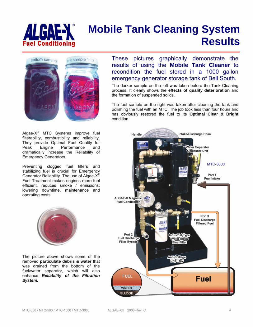
These pictures graphically demonstrate the results of using the Mobile Tank Cleaner to recondition the fuel stored in a 1000 gallon emergency generator storage tank of Bell South.
The picture above shows some of the removed particulate debris & water that was drained from the bottom of the fuel/water separator, which will also enhance Reliability of the Filtration System.
The darker sample on the left was taken before the Tank Cleaning process. It clearly shows the effects of quality deterioration and the formation of suspended solids. The fuel sample on the right was taken after cleaning the tank and polishing the fuel with an MTC. The job took less than four hours and has obviously restored the fuel to its Optimal Clear & Bright condition.
Algae-X® MTC Systems improve fuel filterability, combustibility and reliability. They provide Optimal Fuel Quality for Peak Engine Performance and dramatically increase the Reliability of Emergency Generators. Preventing clogged fuel filters and stabilizing fuel is crucial for Emergency Generator Reliability. The use of Algae-X® Fuel Treatment makes engines more fuel efficient, reduces smoke / emissions; lowering downtime, maintenance and operating costs.
MTC-3000
MTC-350 / MTC-500 / MTC-1000 / MTC-3000 ALGAE-X® 2006-Rev. C 5
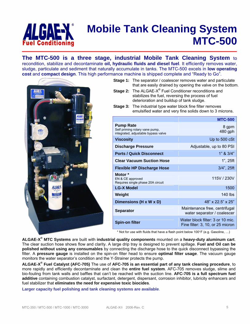
ALGAE-X® MTC Systems are built with industrial quality components mounted on a heavy-duty aluminum cart. The clear suction hose shows flow and clarity. A large drip tray is designed to prevent spillage. Fuel and Oil can be polished without using any consumables by connecting the discharge hose to the quick disconnect bypassing the filter. A pressure gauge is installed on the spin-on filter head to ensure optimal filter usage. The vacuum gauge monitors the water separator’s condition and the Y-Strainer protects the pump. ALGAE-X® Fuel Catalyst (AFC-705) The use of AFC-705 is an essential part of any tank cleaning procedure, to more rapidly and efficiently decontaminate and clean the entire fuel system. AFC-705 removes sludge, slime and bio-fouling from tank walls and baffles that can’t be reached with the suction line. AFC-705 is a full spectrum fuel additive containing combustion catalyst, surfactant, detergent, dispersant, corrosion inhibitor, lubricity enhancers and fuel stabilizer that eliminates the need for expensive toxic biocides. Larger capacity fuel polishing and tank cleaning systems are available.
Mobile Tank Cleaning SystemMTC-500
Stage 1: The separator / coalescer removes water and particulate that are easily drained by opening the valve on the bottom.
Stage 2: The ALGAE-X® Fuel Conditioner reconditions and stabilizes the fuel, reversing the process of fuel deterioration and buildup of tank sludge.
Stage 3: The industrial type water block fine filter removes emulsified water and very fine solids down to 3 microns.
The MTC-500 is a three stage, industrial Mobile Tank Cleaning System to recondition, stabilize and decontaminate oil, hydraulic fluids and diesel fuel. It efficiently removes water, sludge, particulate and sediment that naturally accumulate in tanks. The MTC-500 excels in low operating cost and compact design. This high performance machine is shipped complete and “Ready to Go”.
MTC-500Pump Rate Self priming rotary vane pump, integrated, adjustable bypass valve
8 gpm 480 gph
Viscosity Up to 500 cSt
Discharge Pressure Adjustable, up to 80 PSI
Ports / Quick Disconnect 1” & 3/4”
Clear Vacuum Suction Hose 1”, 25ft
Flexible HP Discharge Hose 3/4”, 25ftMotor * EN & CE approved Requires single phase 20A circuit
115V / 230V
LG-X Model 1500Weight 140 lbs
Dimensions (H x W x D) 48” x 22.5” x 25”
Separator Maintenance free, centrifugalwater separator / coalescer
Spin-on filter Water block filter: 3 or 10 mic.Fine filter: 3, 10, or 25 micron
* Not for use with fluids that have a flash point below 100°F (e.g. Gasoline, …)
MTC-350 / MTC-500 / MTC-1000 / MTC-3000 ALGAE-X® 2006-Rev. C 6
INITIAL INSPECTION
Congratulations on your purchase of an Algae-X® MTC Mobile Tank Cleaning System! Upon delivery, the MTC System and accessories must be visually inspected. Shipping and handling may cause physical or electrical problems. Note any damages with the shipping company or refuse shipment in cases of severe damage.
OVERVIEW - MOBILE TANK CLEANING SYSTEM
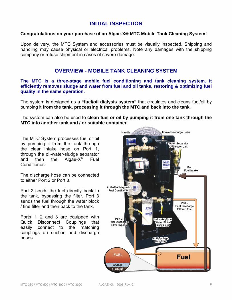
The MTC is a three-stage mobile fuel conditioning and tank cleaning system. It efficiently removes sludge and water from fuel and oil tanks, restoring & optimizing fuel quality in the same operation. The system is designed as a “fuel/oil dialysis system” that circulates and cleans fuel/oil by pumping it from the tank, processing it through the MTC and back into the tank. The system can also be used to clean fuel or oil by pumping it from one tank through the MTC into another tank and / or suitable container. The MTC System processes fuel or oil by pumping it from the tank through the clear intake hose on Port 1, through the oil-water-sludge separator and then the Algae-X® Fuel Conditioner. The discharge hose can be connected to either Port 2 or Port 3. Port 2 sends the fuel directly back to the tank, bypassing the filter. Port 3 sends the fuel through the water block / fine filter and then back to the tank. Ports 1, 2 and 3 are equipped with Quick Disconnect Couplings that easily connect to the matching couplings on suction and discharge hoses.
MTC-350 / MTC-500 / MTC-1000 / MTC-3000 ALGAE-X® 2006-Rev. C 7
TANK CLEANING - WHY, WHERE AND HOW
All storage tanks naturally accumulate water, solids and sludge resulting from condensation and the degradation of fuel and oil. The more fuel we turn over through a tank, the more debris and water will accumulate in the bottom.
Algae-X® Fuel Conditioning and Filtration Systems eliminate the need for costly, periodic manual tank cleaning, while stabilizing and extending the shelf life of fuel. This is extremely important for all applications of long-term fuel storage, especially emergency power generators.
The Algae-X® Mobile Tank Cleaning System is compact, easy to operate and extremely versatile. It is ideal for use:
• in marinas, to clean tanks on board of all types of vessels • at construction sites • in remote areas with on-site fuel storage for heavy equipment • in service trucks maintaining standby generators • in truck/vehicle depots • in hydraulic oil tanks
GENERAL TANK CLEANING PROCEDURE
The MTC has three different operating modes providing the operator flexibility and efficiency.
In Phase One, bulk water and sludge are removed from the tank into a separate container for disposal. In Phase One the fuel bypasses the filter. The Separator/ Coalescer and Algae-X® Fuel Conditioner work in conjunction removing free water, sludge, and particulate, as small as 5 micron, from the tank. The system is not in a re-circulating mode. The fuel enters through Port 1 and exits through Port 2 into a separate waste container. Water and sludge are directly removed from the tank and collected in an appropriate container for disposal.
In Phase Two, the MTC system is in recirculating mode, continuously restoring, reconditioning and returning the fuel back to the tank. Phase Two will continuously remove free water and particles as small as 5 micron using only the water separator and Algae-X® Fuel Conditioner. The fuel enters in Port 1 and returns back to the tank from Port 2. The fuel bypasses the filter, which will economize on consumable filter elements. Phase two will restore the fuel to a clear and bright condition.
In Phase Three, the MTC system is still in a recirculating mode. The fuel enters through Port 1 and exits through Port 3 back to the tank. In addition to the water separator and Algae-X® Fuel Conditioner, this phase incorporates the water block / fine filter removing even invisible particles down to 3 micron, as well as entrained and emulsified water. Phase Three will restore the fuel to its optimal clear and bright condition.
We always recommend keeping a “before” and “after” bottom tank sample for “show & tell” purposes and to demonstrate the improvement of fuel color, clarity and opacity.
MTC-350 / MTC-500 / MTC-1000 / MTC-3000 ALGAE-X® 2006-Rev. C 8
AFC-705 FUEL CATALYST
The use of Algae-X® AFC-705 Fuel Catalyst is an essential part of any tank cleaning procedure, to more rapidly and efficiently decontaminate and clean the entire fuel system. The catalyst is best introduced into the process during Phase Two. Before dosing the tank with AFC-705, remove as much of the sludge and free water as possible. Adding the Algae-X® Fuel Catalyst (AFC-705) to the tank will speed up the cleaning process by breaking down and dissolving the sludge covering the tank walls and baffles. AFC-705 will decontaminate areas and sections of the tank that are out of reach of the suction hose. Using a higher concentration of one to twenty five hundred (1:2500) instead of one to five thousand (1:5000) has proven to be very helpful in accelerating the rate of dissolving the sludge. Even higher doses of AFC-705 may be necessary depending on contamination level of fuel. AFC-705 is a full spectrum fuel additive containing combustion catalyst, surfactant, detergent, dispersant, corrosion inhibitor, lubricity enhancers and fuel stabilizer that eliminates the need for expensive toxic biocides.
AFTER CLEANING THE TANKS
1. Stabilize the Fuel AFC-705 should always be used to stabilize the fuel in tanks used for long-term fuel storage. When no Algae-X® re-circulating system or STS Automatic Filtration System is in place, AFC-705 will maintain fuel quality and prevent formation of solids for six to twelve months. Added during the tank cleaning phase it is not necessary to use AFC-705 again for 6 months or more.
2. Prevent Water from Accumulating The use of Algae-X® Water Eliminators will prevent water from accumulating in the tank. The water eliminators will absorb and remove any future water from condensation or other sources. Preventing water accumulation eliminates microbial growth and the need for toxic biocides.
3. Monitor Fuel Quality Liqui-Cult Fuel Test Kits are ideal to monitor your fuel supply for microbial contamination. The tests quantify bacterial and fungal activity.
• Algae-X® Tank Cleaning Systems significantly lower operating costs, save fuel, eliminate periodic tank cleaning and the build up of solids, sludge and acids.
• Algae-X® Technology enhances personnel safety and addresses environmental concerns by preventing the need for costly toxic biocides.
• Larger capacity Mobile and Stationary Tank Cleaning Systems are available.
MTC-350 / MTC-500 / MTC-1000 / MTC-3000 ALGAE-X® 2006-Rev. C 9
TANK CLEANING “101”
! IMPORTANT ! It is recommended that only qualified, experienced personnel, familiar with this equipment, who have read and understood all the instructions in this manual should operate and maintain the system.
! WARNING ! Do not use with gasoline, solvents, corrosive liquids, food liquids or other liquids having a flash point less than 100°F. Use with gasoline or use with any flammable liquids at a temperature exceeding their flash point, presents an immediate explosion and fire hazard
! IMPORTANT ! All safety measures and practices involving fuel / oil handling should be observed and followed at all times.
! WARNING ! For operator safety the MTC system needs to be connected to a properly grounded power source protected by a breaker and matching the electrical requirements of the pump (see pump label).
NOTE: Contact factory for use of MTC with biodiesel, vegetable oil or other liquid compatibility.
PREPARATIONS
Before operating the MTC, we recommend you first determine the amount of contaminants, free water and sludge in the tank. Algae-X® provides a variety of tank sampling equipment including Sampling Pumps, tubing and bottles as well as Sampling Thieves (“Bacon Bomb”) – please see our FS Fluid Sampling line of products. Please make sure the samples are taken from the bottom of the tank (in the deepest spot). An old and tried method is also “sticking the tank”. This means using a stick with “Kolor Kut” paste on the end that reaches through the top all the way to the bottom of the tank. Kolor Kut paste will show the water level in the tank and indicate how much water and sludge will have to be removed. Call Algae-X® for further information on other fuel sampling equipment.
START–UP PROCEDURE
Note: The MTC System is equipped with a positive displacement vane pump. It should never be run dry and started without the hoses attached and/or valves in the closed position. Failure to do so may damage the bypass valve and / or pump. PRIMING THE SYSTEM Before turning on the pump make sure the entire suction side of the MTC system (suction hose, separator, plumbing, pump, strainer …) is primed and filled with oil / diesel fuel. Running the pump dry could cause pump damage and pump to not operate properly. It is recommended to install an oversized, low restriction foot valve to keep the system primed, especially if the MTC is located above the fuel level in the tank (e.g. underground storage tank).
Note: The separator/coalescer has to be full at all time to perform properly ! IMPORTANT ! Never exceed 15”HG on vacuum gauge located before of pump.
`
`
`
`
`
MTC-350 / MTC-500 / MTC-1000 / MTC-3000 ALGAE-X® 2006-Rev. C 10
OPERATING PROCEDURE – STEP BY STEP
HOSES: The intake/suction hose is a clear, see-through reinforced vacuum hose. The return hose is black or blue/black, non-marking, high quality, discharge fuel hose. Both hoses are equipped with quick disconnects or Cam & Groove couplings.
1. Attach quick disconnect end of clear suction hose to the quick disconnect Port 1 of the MTC.
2. We highly recommend attaching a straight wand or pipe (cut at an angle at the end that goes into the tank) with minimum the same inner diameter as the suction hose to the suction hose to reach the lowest part of the tank bottom.
3. Attach quick disconnect end of blue/black discharge hose to quick disconnect Port 2 of MTC.
4. Place the end of the discharge hose in an appropriate-size container (Phase One only). Try to not agitate the fuel in the tank and stir up and disperse water and sediment throughout the fuel – this will make it more difficult to remove later on.
5. For Phases Two and Three, place the end of the discharge hose back in the tank as far away as possible from the suction hose. Ensure that the hose is secured and will not vibrate out of the container when the system is operating.
6. Verify that both drain valves are closed and the system is set up in a stable and safe position.
Note: Never restrict the flow on the suction side of an MTC; e.g. by using a smaller ID hose or pipe or attaching the suction hose to a fitting on the tank that has a smaller ID than the hose. This will lead to excessive pump load, noise and ultimately damage the pump.
WE ARE NOW READY FOR
PHASE ONE removing of bulk water and sludge from the tank into a separate disposal container. Phase one bypasses the filter.
7. Start the pump motor and be ready to immediately stop it. The vane pump will start pumping as long as the system is primed and the suction lift is not excessive. The flow of fuel can be observed in the see-through suction hose. Watch for a steady flow of fuel into the container.
8. Once the fluid begins to fill the discharge container, immediately switch off the motor and inspect the discharged fluid. Resume pumping and continue the above procedure until water and sludge have been removed from tank bottom and primarily fuel is discharged from the return hose. To remove as much of the free water and sludge as possible, the suction hose with a straight wand or pipe attached should be placed at the deepest part of the tank. If possible, move the suction hose / pipe to different areas of the tank to more efficiently vacuum the sludge off the bottom.
9. After removing the bulk water and sludge from the tank, switch off the pump. Then, drain all water and debris from the hose and the water separator into an appropriate bucket placed under the drain valve.
MTC-350 / MTC-500 / MTC-1000 / MTC-3000 ALGAE-X® 2006-Rev. C 11
PHASE TWO. After removing the bulk of the sludge and water from the tank into a separate container for disposal and draining the separator, the return hose is now inserted into the tank.
10. Insert blue/black discharge hose into tank as far away from the suction hose as possible.
In some cases, it is recommended to remove the sending unit cover to gain sufficient access to the tank. In many cases, both hoses will have to be inserted through the same tank fill opening.
11. After verifying that both hoses are properly placed in the fuel tank and that the valves on the MTC system are in the correct position, switch on the pump and watch the clear suction hose for fuel flow.
Depending on the amount of contaminant in the tank, we recommend you stop the pump shortly after priming and check for free water and sludge by draining the water separator. It may be necessary to depress the air purge valve on top of the separator after opening the drain valve. Repeating this process and observing the fuel flow will indicate how long the pump should run before it is necessary to drain the separator.
12. The MTC should be kept running in the Phase Two recirculating mode until clean fuel samples can be drained from the separator. Then, switch off the pump for final polishing.
13. Now is the time to add Algae-X® AFC-705 Fuel Catalyst in a dose of 1 : 2500 or 1 gal of AFC-705 for 2500 gallons of fuel. Higher doses of AFC-705 may be necessary depending on condition of fuel.
PHASE THREE is the final fine filtration cycle. The fuel now enters in Port 1 and returns back to the tank through the discharge hose connected to Port 3. The fuel now also flows through the water block / fine filter (WB-3 or WB-10) that removes even the finest invisible particles down to 3 micron as well as entrained and emulsified water.
14. Connect the return hose to Port 3. 15. Start the pump and the system will run in the re-circulating mode restoring the fuel to its
optimal pristine and sparkling condition. 16. Monitor the pressure gauge on the filter head. When the pressure reaches 20 - 25 PSI,
or reaches the red area it is time to change the filter. The MTC-3000 is equipped with a differential pressure indicator that will pop up when the filter needs to be changed.
Note: FF-3, FF-10 and FF-25 filers are only for particulate removal and will allow water to pass through – for complete water elimination we highly recommend to finish a tank cleaning job with a WB-3 or WB-10 filter.
! WARNING ! Never run an MTC system unattended.
Note: The built in bypass-valve on the MTC-500 pump can be adjusted for your requirements. If the adjustment screw is all the way out, the valve is set to the lowest possible pressure. Turn screw on bypass valve clockwise to increase by-pass pressure if necessary (see also pump instructions).
`
MTC-350 / MTC-500 / MTC-1000 / MTC-3000 ALGAE-X® 2006-Rev. C 12
FILTERS – MTC 500 / 1000 / 3000
Always have an adequate supply of filter elements. There are two types of Algae-X® spin-on fine filters available.
1 .The standard 3 or 10 or 25 micron fine filter (FF-3, FF-10, FF-25). 2. The special 3 or 10 micron water block fine filter. (WB-3, WB-10) The Algae-X® Water Block removes entrained and emulsified water from fuel and oil.
CHANGING FILTERS The pressure gauge on the filter head shows the pressure drop over the filter. Red or 20-25 PSI indicates when the spin-on filter element should be replaced. On the MTC-3000 the pop up indicator measures the differential pressure over the filter head and will indicate when it is time to change the filter.
1. Before replacing the filter element, place an appropriate container under the drain valves.
2. Open both the drain valve on the separator and the drain valve under the pump. Use the air purge valve on top of the separator to make sure all fluid has been drained from the system before changing the filter. The water block filters are used to remove entrained and emulsified water from the fuel/oil stream. Saturation of water block filter will cause the pressure drop over the filter to increase. When the pressure drop over the filter blocks the fuel flow and the filter element is not changed, the bypass valve in the pump may open and the system will idle. This should only be allowed to happen for no more than 30 seconds.
3. Apply a film of lubricating oil to the gasket of the new filter. Screw filter on to the flow adaptor until the gasket is tight and secure (an additional 1/2 to one turn after the filter makes contact with the gasket).
4. Check for leaks when re-starting and pressurizing the system. The material trapped inside the filter can be inspected to better understand the types of contaminants that have been removed from the tank.
! IMPORTANT ! The internal by-pass valve of the pump can only be operated for less than 30 seconds. Longer periods can lead to overheating the fuel in the pump head, cause fire and explosion hazard as well as damage the pump.
Note: Disposal of tank sludge, water and filter elements should be done in accordance with Federal, State and Local regulations.
`
MTC-350 / MTC-500 / MTC-1000 / MTC-3000 ALGAE-X® 2006-Rev. C 13
FILTERS – MTC 350
It is necessary to prime the filter before initial use. Remove the top filter cover by removing the four wing nuts. Fill the bowl and filter body, as well as the suction line with diesel fuel and replace the cover. The timer can now be set to the desired run time. The pump will automatically shut off after this pre-set time. Set the tell-tale gauge indicator (red pointer) slightly above the black needle prior to operation. The gauge will indicate the maximum vacuum pressure during system operation. When the indicator reaches 15“ HG, it is time to back-flush or change the element. The same procedure is necessary if the water level reaches 30% of the clear bowl. SERVICING AND BACK-FLUSHING THE MTC-350 FILTER:
1. Turn off the MTC-350 pump motor
2. Open the brass colored bleed screw on the top of the filter cover
3. Place a fuel waste container below the yellow safety drain valve at the bottom of the filter bowl
4. Open the yellow safety drain valve (push & turn counter clockwise)
5. Close after approximately 2 seconds
6. After approximately 10 seconds reopen the drain valve
7. Close after visible sediment, particles and water are drained from the bowl
8. Prime the filter by removing the cover (4 wing bolts) and pouring clean diesel fuel into the filter body until the fuel level reaches the top of the filter body
9. Replace the lid. Note: evenly tighten the wing bolts to ensure a good seal
10. Close bleed screw on top of the lid
11. The MTC-350 is ready for operation
Note: Elements can be back-flushed up to 5 times before replacement is required Note: Disposal of tank sludge, water and filter elements should be done in accordance with Federal, State and Local regulations.
MTC-350 / MTC-500 / MTC-1000 / MTC-3000 ALGAE-X® 2006-Rev. C 14
MTC MAINTENANCE
! IMPORTANT ! It is recommended that only qualified, experienced personnel, familiar with this equipment, who have read and understood all the instructions in this manual should install, operate and maintain the system.
! IMPORTANT ! Always disconnect the system from the electric power supply before working or servicing it. Do not proceed with any maintenance unless the pressure or vacuum has been released, the system has been allowed to reach ambient temperature and all fluids have been drained.
DRAINING AND STORING THE SYSTEM 1. Before releasing the quick disconnect couplings, allow all fuel to flow out of the hoses
by draining the system or take the suction hose out of the tank while the pump is still running and wait till system is purged and empty.
2. Place an appropriate container under each drain valve. Open both the valve on the separator and the valve under the pump. Use the air purge valve on top of the separator to make sure all of the fluid can be drained from the system. Opening the valves and the air purge valve will allow fuel to flow down and out of both hoses into the tank.
PUMP STRAINER / Y-STRAINER (MTC-500) Check the pump strainer (located on pump head of MTC-1000 / 3000) or Y-Strainer (MTC-500) frequently for debris and clean as necessary. FUEL / OIL SEPARATOR / COALESCER The separator is a closed dynamic separator / coalescer that does not require any consumables. When draining water and sludge from the separator:
1. Place an appropriate container under the drain valve 2. Open the drain valve and close when observing clean fuel 3. Push the air-purge valve to allow air in and fuel to flow out
The Separator needs to be serviced and flushed from time to time. This can be done by removing the top plug, opening the drain valve on the bottom and flushing the separator to make sure no debris and contaminants restrict the flow. PUMP Check pump for leaks, worn vanes and if bypass valve operates correctly. We highly recommend carrying a spare pump. The MTC pump can be easily changed in a matter of minutes by opening the unions and/or short hose connections. Spare part kits are also available for all MTC pumps. Keep the pump lubricated and pour some oil into pump head for storage. LG-X FUEL CONDITIONER Ferrous particles and rust can collect inside the LG-X unit and over time cause a flow restriction and/or diminish its effectiveness. Open the lid of the LG-X Fuel Conditioner by unscrewing the lid screws and clean the magnet and fuel chamber. Inspect O-rings prior to reassembly. SUCTION AND DISCHARGE HOSES We recommend replacing the suction hose every year and the discharge hose every two years. Heavy use, visual deterioration, damage or poor condition and excessive wear can require an even earlier change.
`
`
MTC-350 / MTC-500 / MTC-1000 / MTC-3000 ALGAE-X® 2006-Rev. C 15
SAFETY NOTES
The MTC Pump is designed to be used with diesel fuel and oils only. The pump is NOT designed for gasoline, alcohol or other explosive or corrosive liquids. Please contact us if you are not sure if the liquid you are intending to polish and clean is compatible with the MTC system. Biocides are extremely toxic and may enter the body through the skin. It is recommended to use adequate protection and avoid skin contact with biocide-treated fuels and oil. Disposal of tank sludge, water and filter elements should be done in accordance with Federal, State and Local regulations. These materials need to be treated as chemical waste.
! WARNING ! DO NOT USE WITH GASOLINE. This System is not meant for use with gasoline nor with other flammable liquids having a flash point less than 100°F (38°C). Use with gasoline or any flammable liquids at a temperature exceeding their flash point, presents explosion and fire hazards.
! WARNING ! Care must be taken not to operate the pump with either the suction (inlet) or discharge (outlet) lines closed or obstructed. If the pump is allowed to run without fuel serious damage may occur. Only run the system when you are able to supervise it. Unattended Operating of the MTC is NOT recommended.
! WARNING ! Some fuels may have been treated with biocides. Biocides are extremely toxic and may enter the body through the skin. Use adequate protection and avoid contact.
Note: Disposal of tank sludge, water and filter elements should be done in accordance with Federal, State and Local regulations.
TROUBLESHOOTING
No fuel delivery 1. Pump does not run 2. Pump / MTC is not primed or looses prime 3. Fuel supply or return blocked 4. Separator / LG-X Fuel Conditioner / Pump or Y-Strainer clogged 5. Lift is too high 6. Air leak in fuel supply to pump 7. Intake or outlet valve closed 8. Liquid too viscous (thick) 9. Foot valve clogged / inoperative
Insufficient fuel delivered 1. Air leak at inlet 2. Defective pressure relief valve 3. Lift too high 4. Pump worn 5. Inoperative / too small foot valve 6. Flow restriction in hose / plumbing / Coalescer / Strainer / LG-X Fuel Conditioner 7. Liquid too viscous 8. Filter plugged
`
`
`
MTC-350 / MTC-500 / MTC-1000 / MTC-3000 ALGAE-X® 2006-Rev. C 16
Rapid pump wear 1. Pump has been run dry or with insufficient fuel / lubrication 2. Restriction on inlet side of pump (e.g. ID too small on suction pipe, excessive hose length, too small fitting on
tank, …)
Vacuum gauge shows more than 15”HG: 1. Restriction on inlet side too high 2. Lift too high 3. Inoperative foot valve 4. Inlet ball valve not fully open 5. Suction line / Coalescer / Strainer / LG-X Fuel Conditioner clogged
Pressure gauge in red area or more than 20 – 25 PSI with clean or new filter element installed 1. Restriction on discharge side too high 2. Head (lift) on discharge side too high 3. Check filter for water saturation (WB only) 4. Outlet ball valve not fully open 5. Discharge line clogged
Noisy operation 1. Insufficient fuel supply 2. Air leaks in the inlet pipe 3. Excessive pump load (vacuum > 15”HG) 4. Air or gas on the suction side
Pump requires frequent re-priming 1. Inoperative foot valve 2. Pump cavitations 3. Plumbing air leaks 4. Lift too high 5. Leaking pump seal
Motor does not turn or turns intermittently 1. Control power not available 2. Motor thermal overload condition 3. Pump failed and seized 4. Motor failure
Pump leaks fuel 1. Loose pump plumbing fittings 2. Worn pump shaft seal 3. Pump pressure relief valve failure 4. Fuel leak elsewhere and fuel dripping or running towards the pump 5. Excessive head from overhead storage tank 6. Worn pump O-rings or seals\
Note: We highly recommend installing the optional Digital Flow Meter in the discharge hose of the MTC (can also be factory equipped – if requested). The Digital Flow Meter is an excellent tool to monitor the performance of the equipment and will measure how much fuel has been processed through the MTC.
MTC-350 / MTC-500 / MTC-1000 / MTC-3000 ALGAE-X® 2006-Rev. C 17
TANK CLEANING SYSTEMS WARRANTY
LIMITED WARRANTY
ALGAE-X® International makes every effort to assure that its products meet high quality and durability standards and expressly warrants the products described herein, against defects in material and workmanship for a period of one (1) year from the date of purchase. This warranty is not intended to supplant normal inspection, care and service of the products covered by the user, and shall not obligate ALGAE-X® to provide free service during the warranty period to correct breakage, maladjustment or other difficulties arising out of abuse, misuse, or improper care and maintenance of such products. Our express warranty is subject to the following terms and conditions: 1. This warranty shall only extend to and is only for the benefit of original purchasers who use the products
covered hereby 2. Any warranty claim received by ALGAE-X® after one (1) year from the date of purchase will not be honored
even if it is claimed that the defect occurred prior to one (1) year from the date of purchase. 3. This warranty shall not apply to products (1) which have been tampered with, altered or repaired by anyone
other than ALGAE-X® without the express prior written consent of ALGAE-X® (2) which have been installed improperly or subject to misuse, abuse, accident, negligence of others, improper operation or maintenance, neglect or modification, or (3) which have had the serial number altered, defaced or removed.
4. The liability of ALGAE-X® under this warranty is limited to the repair or replacement of the defective product.
ALGAE-X® assumes NO LIABILITY for labor charges or other costs incurred by any purchaser incidental to the service, adjustment, repair, return, removal or replacement of products. ALGAE-X® ASSUMES NO LIABILITY FOR ANY GENERAL, SPECIAL, INCIDENTAL, CONSEQUENTIAL, CONTINGENT OR OTHER DAMAGES UNDER ANY WARRANTY, EXPRESS OR IMPLIED, AND ALL SUCH LIABILITY IS HEREBY EXPRESSLY EXCLUDED.
5. ALGAE-X® MAKES NO WARRANTIES, EXPRESS OR IMPLIED, OF MERCHANTABILITY, FITNESS FOR A
PARTICULAR PURPOSE OR OTHERWISE, WITH RESPECT TO THE PRODUCTS COVERED BY THIS WARRANTY POLICY, EXCEPT AS EXPRESSLY PROVIDED FOR HEREIN. NO EMPLOYEE, AGENT, REPRESENTATIVE OR DISTRIBUTOR IS AUTHORIZED TO MAKE ANY WARRANTY ON BEHALF OF ALGAE-X® OTHER THAN THE EXPRESS WARRANTY PROVIDED FOR HEREIN.
6. ALGAE-X® reserves the right at any time to make changes in the design, material, function and specifications
of its products. Any such changes shall not obligate ALGAE-X® to make similar changes in such products that were previously manufactured.
WARRANTY CLAIM PROCEDURE To make a claim under this warranty, please call our ALGAE-X® at (239) 690 9589 or (877) 425-4239, and provide: Name and location where unit was purchased, the date and receipt of purchase, model number, serial number, and a detailed explanation of the problem you are experiencing. The Customer Service Representative may, at the discretion of ALGAE-X®, arrange for a Field Engineer to inspect your system. If the inspection discloses a defect covered by its limited warranty, ALGAE-X® will either repair or replace the defective parts or products. ALGAE-X® assumes no liability, if upon inspection, ALGAE-X® or its representative determines that there is no defect or that the damage to the system resulted from causes not within the scope of this limited warranty. For service and sales, please contact ALGAE-X®:
ALGAE-X® International 5400-1 Division Drive, Fort Myers, FL 33905 ▪ 877-425-4239 ▪ Fax: 239-690-1195
Internet: www.algae-x.net ▪ Email: [email protected]
MTC-350 / MTC-500 / MTC-1000 / MTC-3000 ALGAE-X® 2006-Rev. C 18
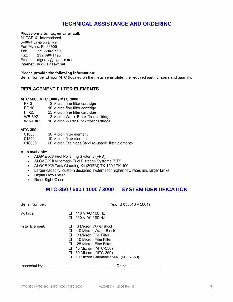
TECHNICAL ASSISTANCE AND ORDERING
Please write to, fax, email or call: ALGAE-X® International 5400-1 Division Drive Fort Myers, FL 33905 Tel: 239-690-9589 Fax: 239-690-1195 Email: [email protected] Internet: www.algae-x.net Please provide the following information: Serial Number of your MTC (located on the metal serial plate) the required part numbers and quantity.
REPLACEMENT FILTER ELEMENTS MTC 500 / MTC 1000 / MTC 3000: FF-3 3 Micron fine filter cartridge FF-10 10 Micron fine filter cartridge FF-25 25 Micron fine filter cartridge WB-3AZ 3 Micron Water Block filter cartridge WB-10AZ 10 Micron Water Block filter cartridge MTC 350: 01830 30 Micron filter element 01810 10 Micron filter element 01860S 60 Micron Stainless Steel re-usable filter elements Also available:
• ALGAE-X® Fuel Polishing Systems (FPS) • ALGAE-X® Automatic Fuel Filtration Systems (STS) • ALGAE-X® Tank Cleaning Kit (3GPM) TK-150 / TK-100 • Larger capacity, custom designed systems for higher flow rates and larger tanks • Digital Flow Meter • Rotor Sight Glass
MTC-350 / 500 / 1000 / 3000 SYSTEM IDENTIFICATION
Serial Number: ____________________________ (e.g. B 030010 – 5001) Voltage: 110 V AC / 60 Hz 230 V AC / 50 Hz Filter Element: 3 Micron Water Block
10 Micron Water Block 3 Micron Fine Filter 10 Micron Fine Filter 25 Micron Fine Filter
10 Micron (MTC-350) 30 Micron (MTC-350) 60 Micron Stainless Steel (MTC-350) Inspected by: ______________________________ Date: ________________
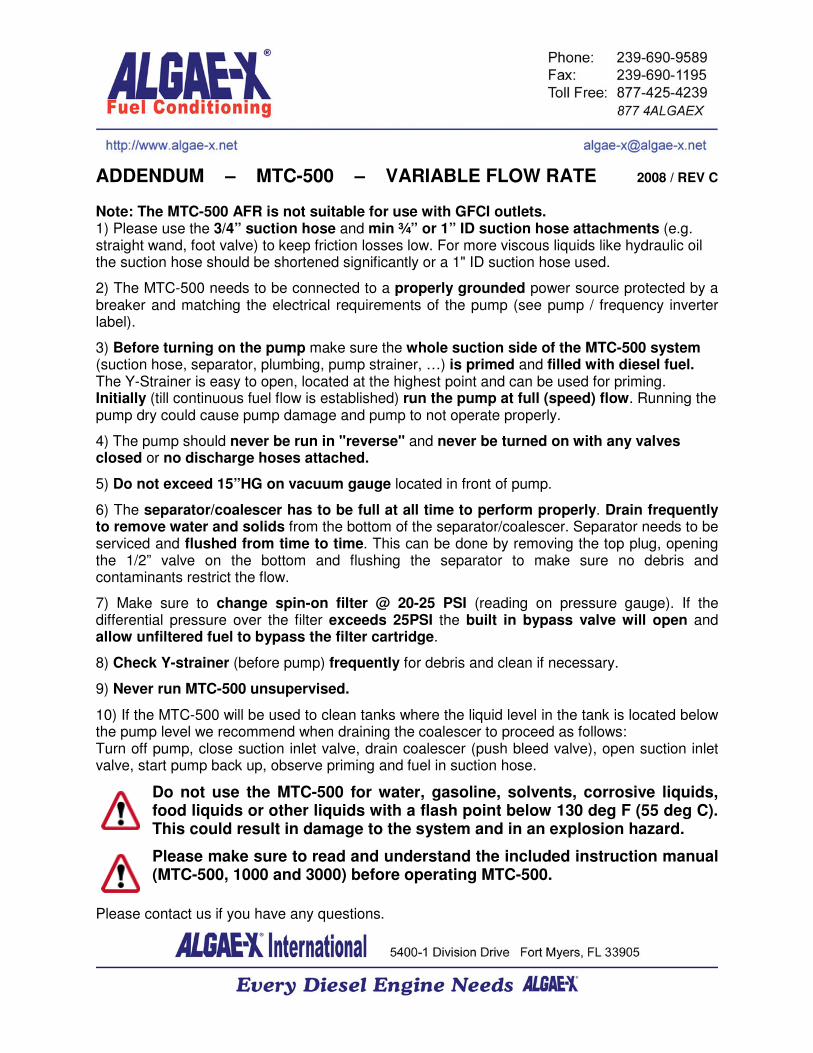
ADDENDUM – MTC-500 – VARIABLE FLOW RATE 2008 / REV C
Note: The MTC-500 AFR is not suitable for use with GFCI outlets.
1) Please use the 3/4” suction hose and min ¾” or 1” ID suction hose attachments (e.g. straight wand, foot valve) to keep friction losses low. For more viscous liquids like hydraulic oil the suction hose should be shortened significantly or a 1" ID suction hose used.
2) The MTC-500 needs to be connected to a properly grounded power source protected by a breaker and matching the electrical requirements of the pump (see pump / frequency inverter label).
3) Before turning on the pump make sure the whole suction side of the MTC-500 system (suction hose, separator, plumbing, pump strainer, …) is primed and filled with diesel fuel. The Y-Strainer is easy to open, located at the highest point and can be used for priming. Initially (till continuous fuel flow is established) run the pump at full (speed) flow. Running the pump dry could cause pump damage and pump to not operate properly.
4) The pump should never be run in "reverse" and never be turned on with any valves closed or no discharge hoses attached.
5) Do not exceed 15”HG on vacuum gauge located in front of pump.
6) The separator/coalescer has to be full at all time to perform properly. Drain frequently to remove water and solids from the bottom of the separator/coalescer. Separator needs to be serviced and flushed from time to time. This can be done by removing the top plug, opening the 1/2” valve on the bottom and flushing the separator to make sure no debris and contaminants restrict the flow.
7) Make sure to change spin-on filter @ 20-25 PSI (reading on pressure gauge). If the differential pressure over the filter exceeds 25PSI the built in bypass valve will open and allow unfiltered fuel to bypass the filter cartridge.
8) Check Y-strainer (before pump) frequently for debris and clean if necessary.
9) Never run MTC-500 unsupervised.
10) If the MTC-500 will be used to clean tanks where the liquid level in the tank is located below the pump level we recommend when draining the coalescer to proceed as follows: Turn off pump, close suction inlet valve, drain coalescer (push bleed valve), open suction inlet valve, start pump back up, observe priming and fuel in suction hose.
Do not use the MTC-500 for water, gasoline, solvents, corrosive liquids, food liquids or other liquids with a flash point below 130 deg F (55 deg C). This could result in damage to the system and in an explosion hazard.
Please make sure to read and understand the included instruction manual (MTC-500, 1000 and 3000) before operating MTC-500.
Please contact us if you have any questions.
`
`