Embed Size (px)
Citation preview

Owners Copy: SAVE THESE INSTRUCTIONS for future referen ce
MT60EVOSect ional Garage Door Opener
Instal lat ion and Operating Instru cti ons
This manual cont ains IMPORTANT SAFETY informationDO NOT PROCEED WITH THE INSTALLATION BEFORE READING THOROUGHLY N2966N2966N2966N2966
gomerlin.co m.augomerlin.co .nz

1
CONTENTS PAGESAFETY INSTRUCTIONS . . . . . . . . . . .1BEFORE YOU BEGIN . . . . . . . . . . . . . .2DOOR TYPES . . . . . . . . . . . . . . . . . . . .2CARTON INVENTORY . . . . . . . . . . . . .3RAIL SIZES . . . . . . . . . . . . . . . . . . . . . .3TOOLS REQUIRED . . . . . . . . . . . . . . . .4HARDWARE PROVIDED . . . . . . . . . . . .4COMPLETED INSTALLATION . . . . . . . .4CONTROL PANEL . . . . . . . . . . . . . . . . .5ASSEMBLY . . . . . . . . . . . . . . . . . . . . . .6INSTALLATION . . . . . . . . . . . . . . . . .7-10OPERATE THE MANUAL RELEASE . .10ADJUSTMENT . . . . . . . . . . . . . . . .11-12INSTALL THE PROTECTORSYSTEM (OPTIONAL) . . . . . . . . . . . . .13
INSTALL WIRELESS WALLBUTTON . . . . . . . . . . . . . . . . . . . . . . . .14TIMER TO CLOSE . . . . . . . . . . . . . . . .14INSTALL WARNING LABELS . . . . . . .15PARTIAL OPENING FEATURE . . . . . .15WIRELESS PROGRAMMING . . . . . . .16USING YOUR OPENER . . . . . . . . . . .17CARE OF YOUR OPENER . . . . . . . . .17REPLACE BATTERIES INREMOTE . . . . . . . . . . . . . . . . . . . . . . .17ACCESSORIES . . . . . . . . . . . . . . . . . .18REPLACEMENT PARTS . . . . . . . .18-19TROUBLESHOOTING . . . . . . . . . . 20-21SPECIFICATIONS . . . . . . . . . . . . . . . .22WARRANTY . . . . . . . . . . . . . . . . . . . . .23
Warning: If your garage has no servic e entranc e door, a CM1702 outside quick release must be installe d. Thisaccessory allows manual operatio n of the garage door from outside in case of power failur e.
The Protecto r System TM must be used for all installationswher e the clo sing force as measured on the bottom of thedoor is over 400 N (40 kgf). Excessive force will interfere withthe proper operation of the Safety Reverse System or damagethe garage door.
SPECIAL NOTE: Merlin strongly recommends that TheProtector SystemTM be installed on all garage door openers.After ins tallation, ensure that the parts of the door do notextend over public foot paths or roads.
Install the wireless wall control (or any additional wall control) ina location wher e the garage doo r is visible, at a heig ht of atleast 1.5 m and out of the reach of children. Do not allowchildr en to operate push button (s) or transmitter(s). Seriouspersonal injury from a closing garage door may result frommisuse of the opener.
Permanently fasten the Warning Labels in Prominen t Places,adjacent to Wall Controls and on manual release mechanism asa reminder of safe operating procedures.
Activa te opener only when the door is in fu ll view, free ofobst ructions and the opener is prop erly adjusted. No oneshou ld enter or leave the garage while the doo r is in motion.
Aut omatic Door- The door may operate unexpectedly, thereforedo not allow anything to stay in the path of the door.
Do not allow children to play near the door, or with doorcont ro ls. Keep remot es away from children.
Discon nect electric powe r to the garage doo r opener beforemaking repair s or removin g covers.
If the supply cord is damaged, it must be replaced by themanufacturer, its service agent or similarly qualified persons inorder to avoid hazard.
This opener should not be installed in a damp or wet spaceexpo sed to weather.
To avoid damage to very light doors (such as fibreglass,aluminium or steel doors), an appropriate reinforcement shouldbe added. To do so, contact the door manufacturer.SAVE THESE INSTRUCTIONS
• Failure to comply with the followi ng instructions may result in serious personal injury or proper ty damage.• Read and foll ow all inst ruc tions carefully.• The garage door opene r is designed and tested to offe r safe serv ice, provided it is installed and operated instrict accordance wit h the inst ructi ons in this manual.
These safety alert symbols mean WARNING : A possible risk to persona l safety or propertydamage exis ts.
Keep garage door balanc ed. Do not let the garage dooropener compensate for a binding or sticking garage door.Sticking, binding or unbalanced doors must be repairedbefore installing this opener.
Do not wear rings, watches or loose cloth ing whileinstalling or servicing a garage door opener. Wear gloves,safety goggles and suitable protective clothing whereappropriate.
Frequent ly examine the door instal lat ion, in particularcable, springs and mountings for signs of wear, damage orimbalance. Do not use if repair or adjustment is neededsince springs and hardware are under extreme tensionand a fault can cause serious personal injury.
To avoid serious personal injury from entanglement,remove all ropes, chains and loc ks connected to thegarage door before installing the door opener.
Insta lla tio n and wiri ng must be in compliance with yourlocal building and electrical codes.
The safety reverse sys tem test is very impor tant. Yourgarage door MUST reverse on contact with a 40 mmobstacle placed on the floor. Failure to properly adjust theopener may result in serious personal injury from a closinggarage door. Repeat the test once a month and makeany necessary adjust ments.
This appliance is not intended for use by persons(including children) with reduced physical, sensory ormental capabilities, or lack of experience and knowledge,unless they have been given supervision or instructionconcerning use of the appliance by a person responsiblefor their safety.
Use the Manual Release only for the seperation of thecarriage from the drive and - if possible - ONLY with thedoor closed. Do not use the red handle to push the doorup or pull it down. Operation of the emergency release canlead to uncontrolled movements of the door, if springs areweak or broken or if the door is unbalanced. Mount therelease handle of the emergency release at a height lessthan 1.8 m from the floor.
START BY READING THESE IMPORTANT SAFETY INSTRUCTIONS
WARNING!

2
BEFORE YOU BEGIN:1. Look at the wall and ceiling above the garage door. (The opener and header bracket must be securely fastened to structuralsupports.)
2. Do you have a finished ceiling in your garage? If so, a support bracket and additional fastening hardware (not supplied) maybe required.
3. Do you have an access door in addition to the garage door? If not, model CM1702 Outside Quick Release Accessory isrequired. This accessory allows manual operation of the garage door from outside in case of power failure.
4. Complete the following test to make sure your garage door is balanced and is not sticking or binding:• Lift the door about halfway. Release the door. If balanced, it should stay in place, supported entirely by its springs.• Raise and lower the door to see if there is any binding or sticking, 20 kgf is the absolute maximum allowable force to raise orlower the door in any position. If your door binds, sticks, or is out of balance, call a trained door technician.
DOOR TYPES
A. Sectional Door with curved track
To suit spring balanced Residential Sectional doorsup to 13.5 m2.
1
Electrical ConnectionA 240 V General Purpose Outlet (GPO) ie. Power Point must be available in close proximity to the powerhead.This fitting is not part of the Opener hardware and must be supplied by the consumer.

12
45
6 78
9
10
11
3
serv
ice:
ww
wch
ambe
rlain
dein
fo@
cham
berla
inde BB
BA
A
en
ACHTUNG - EinklemmgefahrRegelmässig überprüfen und wenn notwendig einstellen umsicher zu sein dass das Tor umkehrt wenn es einen 50 mmhohen Gegenstand berührt der auf den Boden gestellt wurde
de
CAUTION - Danger of EntrapmentRegularly check and adjust if necessary to ensure that thedoor reverses when it touches a 50 mm high object thatis placed on the floor
frATTENTION - Risque d’écrasementVérifier régulièrement et eégler si nécessaire pour s assurerque la porte inverse son mouvement lorsqu elle rencontre unobjet de 50 mm de haut placé sur le sol
ptATENÇÃO - Perigo de entalamentoVerificar regularmente e se necessário ajustar para seassegurar de que o portão volta para trás ao tocar numobjecto com uma altura de 50 mm que foi clocado no chão
nlLET OP - InklemmingsgevaarRegelmatig controleren en indien nodig instellen om zekerte zijn dat de poort terugdraait als deze een 50 mm hoogobject aanraakt dat op de grond werd geplaatst
esATENCIÓN - Peligro de aprisionamientoComprobar regularmente y ajustar cuando sea necessariopara garatizar que la puerta se invierta cuando toca unobjeto de 50 mm de altura que se colocó en el suelo
daADVARSEL - fare for indklemmingPorten skal kontrolleres og om nøvendigt justeres for atsikre at den går tilbage når den berører en 50 mm højgenstand der er blevet stillet på jorden
itATTENZIONE - Pericolo di incastroVerificare sistematicamente e se necessario regolare inmaniera adeguata onde assicurare che la porta torni indietrose viene in contatto con un oggetto alto 50mm posto a terra
noFORSIKTIG - KlemmefareEtter at døren har berørt en gjenstand som har stått 50mm overgulvhøyde må du jevnlig sjekke om døren går feilfrittJuster om nødvendig
HUOMIO - puristumisvaaraTarkista säännöllisesti ja milloin tarpeellista säädä ollaksesivarma että portti kääntyy takaisin kun se koskettaa 50 mmkorkeaa kohdetta joka on asetettu maan pinnalle
fi
el
svVARNING - klämningsriskKontrollera regelbundet och justera om det behövs för att varasäker på att porten vänder när den träffar ett 50 mm högtföremål som placerats på golvet
hr
cz
tr
ro
sk
sr
ro
sk
sr
hu
sl
bg
pl
cn
rus
114A4354
13 12
OwnersCopy:SAVETHESEINSTRUCTIONSforfuturereference
MT60EVOSectional Garage Door Opener
Installation and Operating Instructions
This manual contains IMPORTANT SAFETY informationDO NOT PROCEED WITH THE INSTALLATION BEFORE READING THOROUGHLY N2966N2966N2966N2966
gomerlin.com.augomerlin.co.nz
CARTON INVENTORY
(1) Opener(2) Hand held transmitter (2)(3) Wireless wall control(4) Curved door arm(5) Hanging bracket (2)(6) Rail bracket(7) Header bracket
(8) Door bracket(9) Hardware bag(10) Rail assembly (separate carton)(11) C-Rail bracket (2)(12) Manual(13) Warning Labels
Your garage door opener and rail are packed in two seperate cartons. The PowerAce MT60EVO opener carton contains theopener, its fitting hardware and accessories. The rail carton contains the rail and some hardware.Rails:Different length rails (2.2 m & 2.4 m) are available for different height doors, ensure you have the correct one.
2
RAIL SIZES AVAILABLE3
NOTE: The Ceiling Fixing Point (Standard) is the position of the hanging bracket measured back from the lintel (seeitem 1 to 7 of “completed installation”). Also allow 400 mm back from the fixing point for installation of the powerhead(item 7 to 9 of “completed installation”).The Alternate Fixing Point will position the hanging bracket between the C-Rail brackets, and may line up with astructural support more favourably.
3
DOOR HEIGHT:Sectional Doors
BELT & RAILPART NUMBER:
RAIL LENGTH: CEILING FIXINGPOINTS: (Standard)
ALTERNATEFIXING POINT:
Up to 2.2 m 8022 CR5 3000 mm single piece 2840 mm 2950 mm
Up to 2.2 m 8322 CR5 3000 mm segmented 2840 mm 2950 mm
Up to 2.4 m 8024 CR5 3200 mm single piece 3040 mm 3150 mm
From 2.4 - 3.4 m 840 CR5 1000 mm extension 4040 mm 4150 mm
4
4
1 2 34 5
78
9
10
11
6
1213
14
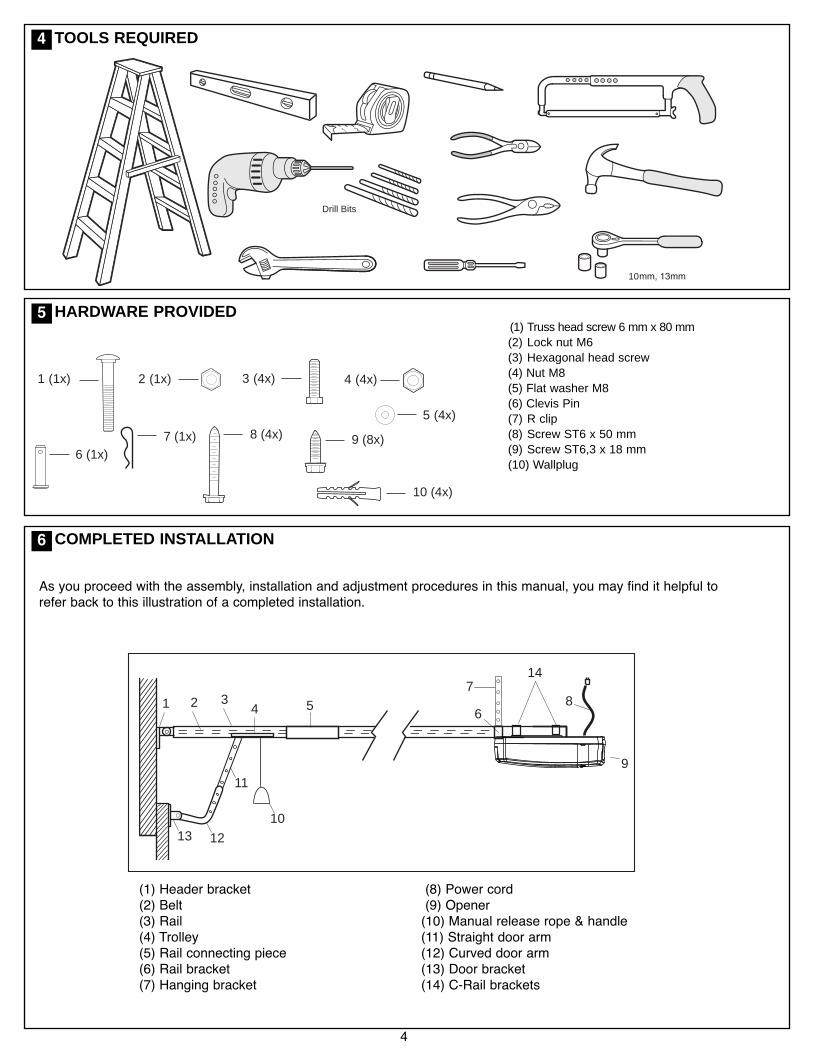
(1) Header bracket(2) Belt(3) Rail(4) Trolley(5) Rail connecting piece(6) Rail bracket(7) Hanging bracket
(8) Power cord(9) Opener(10) Manual release rope & handle(11) Straight door arm(12) Curved door arm(13) Door bracket(14) C-Rail brackets
As you proceed with the assembly, installation and adjustment procedures in this manual, you may find it helpful torefer back to this illustration of a completed installation.
COMPLETED INSTALLATION
10 (4x)
9 (8x)8 (4x)7 (1x)6 (1x)
1 (1x) 2 (1x) 3 (4x) 4 (4x)
5 (4x)
HARDWARE PROVIDED
Drill Bits
10
TOOLS REQUIRED4
5
6
(1) Truss head screw 6 mm x 80 mm(2) Lock nut M6(3) Hexagonal head screw(4) Nut M8(5) Flat washer M8(6) Clevis Pin(7) R clip(8) Screw ST6 x 50 mm(9) Screw ST6,3 x 18 mm(10) Wallplug

30 V DC
+ -
0 1 2 2 3 4 5 6 7
UP
DOWN
PROG
LEARN(YELLOW)
INDICATORLED
12
3
4
56
7
8
1. External Accessory Power: 30 Vdc 50 mA available for universal receiver (not active in Low standby mode).
2. Terminal Block: used for external accessories (see chart below).
3. UP Button: used for initial programming, to drive the door UP, and for displaying Diagnostic Code - Digit 1.
4. PROG Button: used to program door limits, and other features.
5. DOWN Button: used for initial programming, to drive the door DOWN, and for displaying Diagnostic Code - Digit 2.
6. LEARN Button: used to program remote controls and learn the forces manually.
7. Indicator LED: used to indicate various programming modes.
8. Green Button: used to activate the door when remote controls are not available. Open - Stop - Close via fingeraccess through the hole in the access cover.
No Funct ion Colour Polari ty Commen t
0 E-Serial port Green +ve Serial Communication Input
1 Push button Red +ve Dry Contact input for push button wired wall controls
2 Ground White -ve Common terminal for push button
2 Ground White -ve Common terminal for IR Beams
3 IR Sensor Gray +ve Merlin IR Beam Input: (pulsing type only)
4 Door-in-door Green +ve For Door in Door dry contact sensor: (4&5 are normally linked)
5 Door-in-door Green -ve Common terminal for Door in Door sensor
6 Flasher Black +ve Flashing light output: (24 Vdc 150 mA) while door is in motion
7 Flasher White -ve Flashing light output: negative terminal
CONTROL PANEL (located under the cover at the rear of the opener)
5
7

ASSEMBLY SECTION
6
37 - 41 mm
1
TIGHTEN THE BELTNote: The spring must be able to compress and bounceduring operation. Final tensioning can be performed afterinstallation if necessary. Over tightening the belt mayoverload the system and cause excessive wear.1.Tension the belt by adjusting the nut (1), on the pulleyassembly, clockwise until the spring is engaged.
2.Continue tightening to compress the spring and remove all theslack in the belt. DO NOT OVERTIGHTEN but ensure belt isfirm.
3.37-41 mm as indicated in the diagram is normal.
3
4
5
2
X
A1
1.Slide the RAIL BRACKET (1) onto the powerhead end of therail (A) around 200 mm.
2.Remove transport lock (X). Check if the belt is seated on thegearwheel. If it has slipped off during assembly, relax thespring and tighten again.
3.Position the rail drive spocket (2) over the opener motor shaft(3) and push down to install.
4.Secure the rail on the opener with two C-Rail brackets (4) andthe screws (5).
This completes the assembly of the door opener to the rail.
FASTEN RAIL TO OPENER
9
10
NOTE: For 1 piece preassembled rails, proceed to the next step “TIGHTEN THE BELT”.The segmented rail is largely preassembled and consists of 3 parts. The carriage, push rod, release handle, the guide pulleyand the lintel bracket with belt tensioner are in the front part (A). The seating for the drive shaft and the sprocket are in therear part (B). Hardware items are placed in the rails during transportation - remove these. Lay the front and rear rail sectionsone behind the other.1. Remove cable ties that secure the belt. Leave the transport lock (X) still in position.2. Pull apart the two rail sections completely in order to create a gap for the middle section (C). This rail is designed in such away so as to easily add the middle section. Slide the 2 connecting pieces (D) over the seams of the rail sections up to themarkings. To secure the connecting pieces, bend the sheet metal lugs outwards with a suitable tool. The assembly of the rail iscomplete.
ASSEMBLING THE 3 PIECE SEGMENTED RAIL8

7
Wear protective goggles when working overhead to protect your eyes from injury.Disengage all existing garage door locks to avoid damage to the garage door.To avoid serious personal injury from entanglement, remove all ropes connected to the garage door beforeinstalling the opener.
INSTALLATION SECTION
Header Wall
2
Level(optional)
1
3
StructuralSupports
OPTIONALCEILINGMOUNTFORHEADERBRACKET
UnfinishedCeiling
4
2
The header bracket must be rigidly fastened to astructural support of the garage. Reinforce the wall orceiling with a 40 mm (1-1/2") board if necessary. Failureto comply may result in improper operation of safetyreverse system.You can attach the header bracket either to the header wall(1) or to the ceiling (3). Follow the instructions which willwork best for your particular requirements.With the door closed, mark the vertical centre line (2) of thegarage door. Extend line onto header wall above the door.Open door to highest point of travel. Draw an intersectinghorizontal line (4) on header wall at least 50 mm above highpoint to provide travel clearance for top edge of door.
NOTE: Refer to vertical centre and horizontal lines created inthe previous section for proper placement of header bracket.
A. Wall mount: centre the header bracket (1) on the verticalcentre line (2) with the bottom edge of the header bracket onthe horizontal line (4) (with the arrow pointing toward theceiling). Mark all of the header bracket holes (5). Drill 4.5 mm(3/16") pilot holes and fasten the header bracket with woodscrews (3).
B. Ceiling mount: extend vertical centre line (2) onto the ceiling.Centre the header bracket (1) on the vertical mark no morethan 150 mm (6") from the wall. Make sure the arrow ispointing toward the opener. Mark all of the header bracketholes (5). Drill 4.5 mm (3/16") pilot holes and fasten the headerbracket with wood screws (3). For concrete ceiling mount, useconcrete anchors provided.
2
50 mm
31
4
A
150 mm(6")
1 2
3
5
5
2
31
4
up to200 mm
(50 to 200 mm depending on door type)
INSTALL THE HEADER BRACKET
HEADER BRACKET POSITIONING
1
2
Attach the Rail to the Header Bracket• Position the assembled opener on the garage floor below theheader bracket. Use foam packing material as a protectivebase.
NOTE: If the door spring is in the way youʼll need help.Have someone hold the opener securely on a temporarysupport to allow the rail to clear the spring.• Position the rail bracket against the header bracket.• Align the bracket holes and secure with the 80 mm trussheadscrew and locknut (1) and (2).
ATTACH RAIL TO HEADER BRACKET
11
12
13

8
Rail
Door50 mm spacer shouldbe used to determinethe correct mountingposition
HeaderBracket
50 mm (2”)above the highestpoint of travel
POSITION THE OPENER
SECTIONAL DOORYou will need a 50 mm piece of timber or similar spacer to gauge the distance between door and rail.
1.Raise the opener onto support.
2.Open the door completely, place a 50 mm spacer between the door and the rail (as shown).
3.The final positioning of the rail should be relatively parallel to the horizontal door panels.
14
Disengage the trolley mechanism (see section “Operating the manual release”) and slide it back towards the powerhead.Secure the hanging push arm up into the rail assembly temporarily using tape or rope, to avoid a hazard.

9
3 4
XA
1
2
HANG THE OPENER
100-300 mm
1
AThe door bracket must be securely fastened to the frameor a structural support on the door.
Mounting position for Sectional Doors
1.Align the bracket on the centre line, measure down 100-300 mm from the door top edge.
2.Secure the bracket in this position, using the mostsuitable variation of holes available.
FASTEN DOOR BRACKET
15
16
The opener must be securely fastened to a soundstructural support above the opener.
1.Postion the opener as in the previous step. Check the railis centred over the door.
2.Ensure the rail brackets (1) is on the Powerhead end ofthe rail in a position as close to the opener as possible(X).
3.If mounting directly onto the ceiling, (2) screw the bracketdirectly into a structural support on the ceiling.
4.If hanging the opener below the ceiling, (3 & 4) bend thehanging brackets provided, and secure to both the ceilingand rail bracket.
5.Check the opener is securely centred over the door.Remove the 50 mm spacer, and any other assemblytools. Operate the door manually and check forunrestricted operation.
10
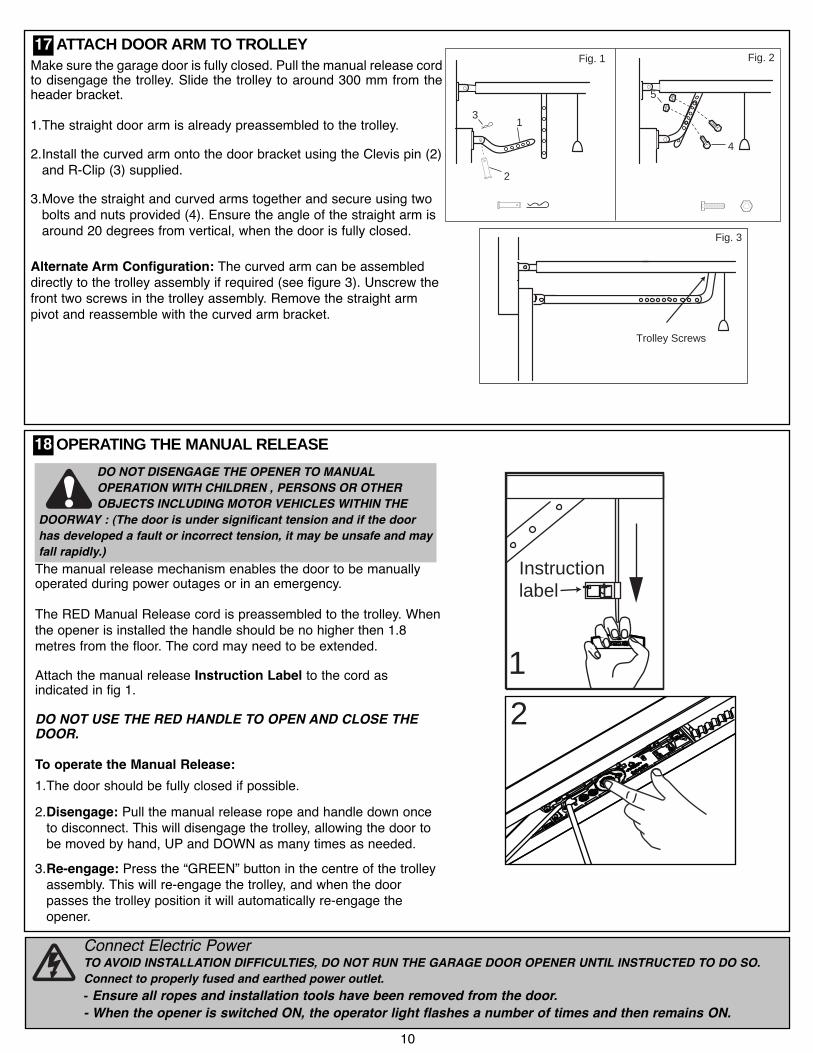
Connect Electric PowerTO AVOID INSTALLATION DIFFICULTIES, DO NOT RUN THE GARAGE DOOR OPENER UNTIL INSTRUCTED TO DO SO.Connect to properly fused and earthed power outlet.- Ensure all ropes and installation tools have been removed from the door.- When the opener is switched ON, the operator light flashes a number of times and then remains ON.
12
Instructionlabel
1
2
3
4
5
Trolley Screws
Fig. 1 Fig. 2
Fig. 3
Make sure the garage door is fully closed. Pull the manual release cordto disengage the trolley. Slide the trolley to around 300 mm from theheader bracket.
1.The straight door arm is already preassembled to the trolley.
2.Install the curved arm onto the door bracket using the Clevis pin (2)and R-Clip (3) supplied.
3.Move the straight and curved arms together and secure using twobolts and nuts provided (4). Ensure the angle of the straight arm isaround 20 degrees from vertical, when the door is fully closed.
Alternate Arm Configuration: The curved arm can be assembleddirectly to the trolley assembly if required (see figure 3). Unscrew thefront two screws in the trolley assembly. Remove the straight armpivot and reassemble with the curved arm bracket.
ATTACH DOOR ARM TO TROLLEY
OPERATING THE MANUAL RELEASE
The manual release mechanism enables the door to be manuallyoperated during power outages or in an emergency.
The RED Manual Release cord is preassembled to the trolley. Whenthe opener is installed the handle should be no higher then 1.8metres from the floor. The cord may need to be extended.
Attach the manual release Instruction Label to the cord asindicated in fig 1.
DO NOT USE THE RED HANDLE TO OPEN AND CLOSE THEDOOR.
To operate the Manual Release:1.The door should be fully closed if possible.2.Disengage: Pull the manual release rope and handle down onceto disconnect. This will disengage the trolley, allowing the door tobe moved by hand, UP and DOWN as many times as needed.
3.Re-engage: Press the “GREEN” button in the centre of the trolleyassembly. This will re-engage the trolley, and when the doorpasses the trolley position it will automatically re-engage theopener.
DO NOT DISENGAGE THE OPENER TO MANUALOPERATION WITH CHILDREN , PERSONS OR OTHEROBJECTS INCLUDING MOTOR VEHICLES WITHIN THE
DOORWAY : (The door is under significant tension and if the doorhas developed a fault or incorrect tension, it may be unsafe and mayfall rapidly.)
17
18
11
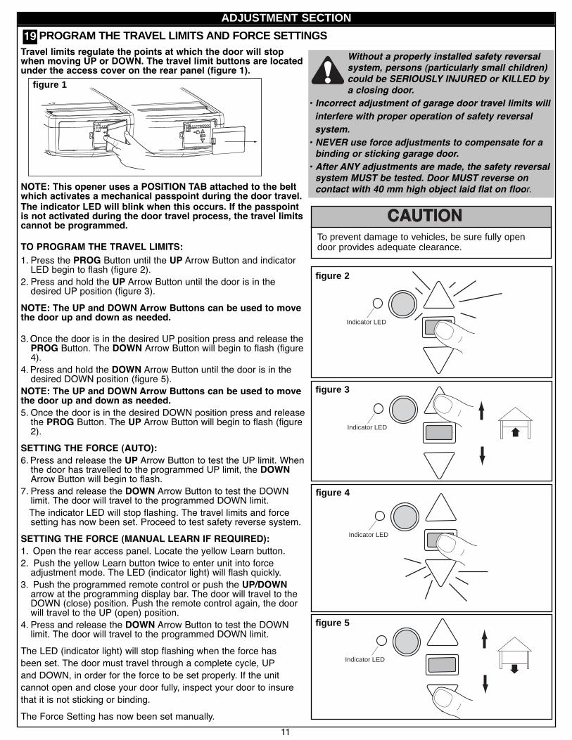
Without a properly installed safety reversalsystem, persons (particularly small children)could be SERIOUSLY INJURED or KILLED bya closing door.
• Incorrect adjustment of garage door travel limits willinterfere with proper operation of safety reversalsystem.• NEVER use force adjustments to compensate for abinding or sticking garage door.• After ANY adjustments are made, the safety reversalsystem MUST be tested. Door MUST reverse oncontact with 40 mm high object laid flat on floor.
To prevent damage to vehicles, be sure fully opendoor provides adequate clearance.
Indicator LED
Indicator LED
figure 2
figure 3
Indicator LED
figure 4
Indicator LED
figur e 5
Travel limits regulate the points at which the door will stopwhen moving UP or DOWN. The travel limit buttons are locatedunder the access cover on the rear panel (figure 1).
NOTE: This opener uses a POSITION TAB attached to the beltwhich activates a mechanical passpoint during the door travel.The indicator LED will blink when this occurs. If the passpointis not activated during the door travel process, the travel limitscannot be programmed.
TO PROGRAM THE TRAVEL LIMITS:1. Press the PROG Button until the UP Arrow Button and indicatorLED begin to flash (figure 2).
2. Press and hold the UP Arrow Button until the door is in thedesired UP position (figure 3).
NOTE: The UP and DOWN Arrow Buttons can be used to movethe door up and down as needed.
3.Once the door is in the desired UP position press and release thePROG Button. The DOWN Arrow Button will begin to flash (figure4).
4. Press and hold the DOWN Arrow Button until the door is in thedesired DOWN position (figure 5).
NOTE: The UP and DOWN Arrow Buttons can be used to movethe door up and down as needed.5. Once the door is in the desired DOWN position press and releasethe PROG Button. The UP Arrow Button will begin to flash (figure2).
SETTING THE FORCE (AUTO):6. Press and release the UP Arrow Button to test the UP limit. Whenthe door has travelled to the programmed UP limit, the DOWNArrow Button will begin to flash.
7. Press and release the DOWN Arrow Button to test the DOWNlimit. The door will travel to the programmed DOWN limit.The indicator LED will stop flashing. The travel limits and forcesetting has now been set. Proceed to test safety reverse system.
SETTING THE FORCE (MANUAL LEARN IF REQUIRED):1. Open the rear access panel. Locate the yellow Learn button.2. Push the yellow Learn button twice to enter unit into forceadjustment mode. The LED (indicator light) will flash quickly.
3. Push the programmed remote control or push the UP/DOWNarrow at the programming display bar. The door will travel to theDOWN (close) position. Push the remote control again, the doorwill travel to the UP (open) position.
4. Press and release the DOWN Arrow Button to test the DOWNlimit. The door will travel to the programmed DOWN limit.
The LED (indicator light) will stop flashing when the force hasbeen set. The door must travel through a complete cycle, UPand DOWN, in order for the force to be set properly. If the unitcannot open and close your door fully, inspect your door to insurethat it is not sticking or binding.The Force Setting has now been set manually.
PROGRAM THE TRAVEL LIMITS AND FORCE SETTINGS
figure 1
ADJUSTMENT SECTION
19

12
TEST THE SAFETY REVERSE SYSTEM
Procedure: With door opened place a 40 mm obstacle (1)laid flat on the floor under the garage door. Operate thedoor in the down direction. The door must reverse off theobstacle. If the door stops on the obstacle, remove obstacleand repeat Program the Limits and Force Steps, thenrepeat safety reverse test.When the door reverses off the 40 mm obstacle, removethe obstacle and run the opener through a complete travelcycle. Door must not reverse in closed position. If it does,repeat Program the Limits and Force then repeat safetyreverse test.
140mm
The safety reverse system test is important. Garage door must reverse on contact with a 40 mm obstaclelaid flat on the floor. Failure to properly adjust opener may result in serious personal injury from a closinggarage door. Repeat test once a month and adjust as needed.
20
Low Standby Mode (sub 1 watt) is activated by the factory to deliver the lowest possible standby power.In this mode the External Accessories Power and the IR Beams are turned OFF when the door is closed and the courtesy lightis OFF.At mains turn ON: Courtesy light flashes 2 times = Low Standby Mode
Courtesy light flashes 10 times = Normal Standby Mode
The Normal Standby Mode will need to be activated for External Accessories Power.
To Activate Normal Standby Mode:Turn the mains power OFF.PRESS and HOLD both the UP and DOWN arrows simultaneously.Turn ON mains power while both the arrow buttons are still pressed.Courtesy light comes on and after 5 seconds another 10 flashes.Release the arrow buttons.
To Activate Low Standby Mode:Turn the mains power OFF.PRESS and HOLD both the UP and DOWN arrows simultaneously.Turn ON mains power while both the arrow buttons are still pressed.Courtesy light comes on and after 5 seconds another 1 flash.Release the arrow buttons.
PROGRAM THE LOW STANDBY MODE (OPTIONAL)21

NOTE: This accessory must be used for all installationswhere the closing force as measured on the bottom of thedoor is over 400 N (40 kgf).SPECIAL NOTE: Merlin strongly recommends that TheProtector SystemTM be installed on all garage dooropeners.
IR BEAMS: By installing IR Beams, an open door is preventedfrom closing if a person or object is located in the beam area. Ifthe door is already closing, it will return to the open position. Aclosed door is not prevented from opening.If the Protector SystemTM is installed and needs to be removed,the opener will need to be reprogrammed (refer to paragraph 4of the troubleshooting section).NOTE: A complete set of installation and setupinstructions are supplied with the accessory item.Figures 1, 2 and 3 show recommended assembly of bracket(s)and "C" wrap based on the wall installation of the sensors oneach side of the door shown above, or on the door tracksthemselves. Figure 4 shows variations which may fit yourinstallation requirements better. Make sure the wraps andbrackets are aligned so the sensors will face each otheracross the door.• Connect each assembly to a slotted bracket, using thehardware shown. Note alignment of brackets for left andright sides of the door. Finger tighten the lock nuts.• Use bracket mounting holes as a template to locate and drilltwo (4.8 mm) diameter pilot holes on both sides of the door sothat the beam mounting height is no greater than 100 mmabove the floor.• Attach bracket assemblies with carriage bolts as shown.• Adjust right and left side bracket assemblies to the samedistance out from mounting surface. Make sure all doorhardware obstructions are cleared. Tighten the lock nuts.• Centre each sensor unit in a "C" wrap with lenses pointingtoward each other across the door.• Secure sensors with the hardware provided. Finger tightenthe wing nut on the receiving eye to allow for final adjustment.Securely tighten the sending eye wing nut.• Run wires from both sensors to the opener and connect thetwo white only wires to the white terminal (2) and theblack/white wires to the grey terminal (3) on your opener (referfigure 5).
Mount BracketWith Square Holes
Screws
“C” Wrap
Lock Nuts
Mounting Bracketwith slot
Lock Nuts
Lag ScrewsCarriage Bolts
(with Square Shoulders)
GarageWall
“C” Wrap
Mounting Bracketwith Square Holes
Garagewall
“C” ShapedWrap
Mounting Bracketswith Square Holes
Carriage Bolts
Lock Nuts
Drill9.5 mmHoles
GarageTrack
Installing The Protector System to Track
ALL INSTALLATIONS
Installing The Protector System to the Garage Wall
TM
TM
“C” Wrap
GarageWall
Mounting Bracketwith Square Holes
Garage-Floor
MountingBracket
with Holes
Alternate Wall Mount
Sensor
GarageWall
Alternate Floor Mount
Mounting Bracketwith Slot
Mounting Bracketwith Square Holes
Holder
Sensor
GarageFloor
Indicator Light
IndicatorLamp
Attach withconcrete anchors
(not provided)
figure 1
figure 2
figure 3
figure 4
6mmred white
To release wires presstab with a screwdriveror pen
figure 5
13
INSTALL THE PROTECTOR SYSTEMTM (OPTIONAL)
To prevent entrapment, install The ProtectorSystem™ no higher than 100 mm above the floor.Disconnect power to the garage door openerbefore installing The Protector System™.
22
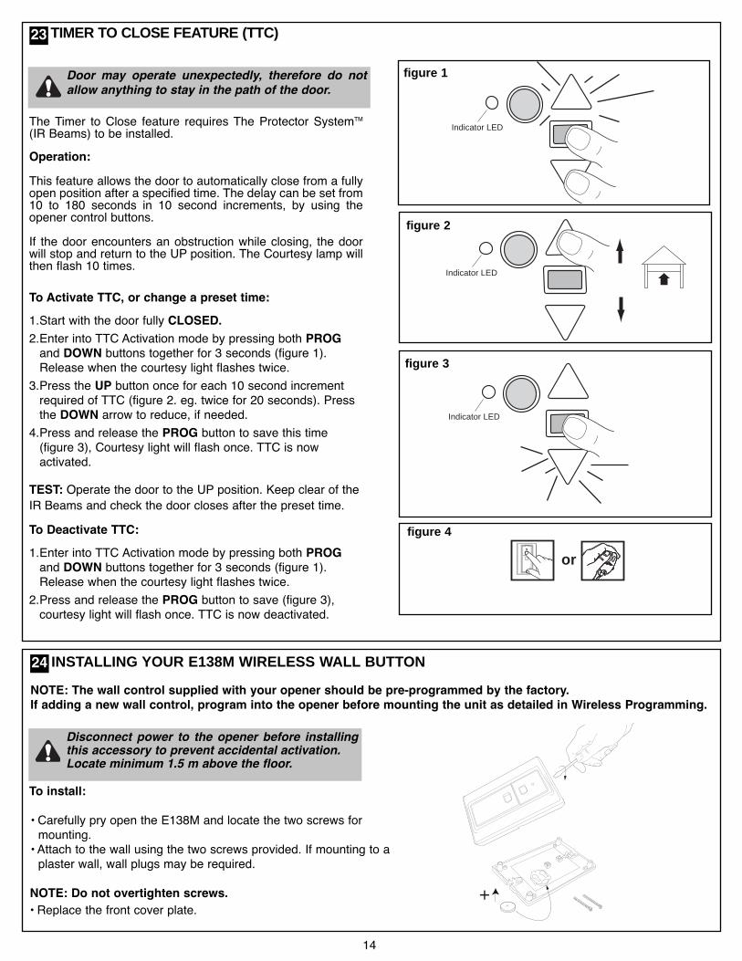
TIMER TO CLOSE FEATURE (TTC)
The Timer to Close feature requires The Protector SystemTM
(IR Beams) to be installed.Operation:This feature allows the door to automatically close from a fullyopen position after a specified time. The delay can be set from10 to 180 seconds in 10 second increments, by using theopener control buttons.If the door encounters an obstruction while closing, the doorwill stop and return to the UP position. The Courtesy lamp willthen flash 10 times.
To Activate TTC, or change a preset time:1.Start with the door fully CLOSED.2.Enter into TTC Activation mode by pressing both PROGand DOWN buttons together for 3 seconds (figure 1).Release when the courtesy light flashes twice.
3.Press the UP button once for each 10 second incrementrequired of TTC (figure 2. eg. twice for 20 seconds). Pressthe DOWN arrow to reduce, if needed.
4.Press and release the PROG button to save this time(figure 3), Courtesy light will flash once. TTC is nowactivated.
TEST: Operate the door to the UP position. Keep clear of theIR Beams and check the door closes after the preset time.To Deactivate TTC:1.Enter into TTC Activation mode by pressing both PROGand DOWN buttons together for 3 seconds (figure 1).Release when the courtesy light flashes twice.
2.Press and release the PROG button to save (figure 3),courtesy light will flash once. TTC is now deactivated.
Indicator LED
Indicator LED
figure 1
figur e 2
Indicator LED
figure 3
or
figure 4
Door may operate unexpectedly, therefore do notallow anything to stay in the path of the door.
INSTALLING YOUR E138M WIRELESS WALL BUTTON
To install:
• Carefully pry open the E138M and locate the two screws formounting.
• Attach to the wall using the two screws provided. If mounting to aplaster wall, wall plugs may be required.
NOTE: Do not overtighten screws.• Replace the front cover plate.
+
Disconnect power to the opener before installingthis accessory to prevent accidental activation.Locate minimum 1.5 m above the floor.
NOTE: The wall control supplied with your opener should be pre-programmed by the factory.If adding a new wall control, program into the opener before mounting the unit as detailed in Wireless Programming.
14
24
23

This is an adjustable, second stop position suitable forventilation, pedestrian or pet access, programmed to the RemoteControl or Wireless Wall button.
To Activate this feature:1.Start with the door fully CLOSED. Drive the opener UP andstop at the position required for PET access.
2.Enter PET activation mode by pressing the PROG and UPbuttons together for 3 seconds (figure 1). Release when theCourtesy light flashes once.
3.Press the Remote Control button that you have allocated forthis feature (figure 4). Do not use the button already allocatedfor normal operation. The Courtesy light will flash once whenthe code is accepted.
TEST: Press the Remote Control once, and door will close, pressagain, and door will return to the preset position.If the door is above the preset position, when the buttonis pressed, it will fully close.
To Deactivate this feature:
1.Start with the door fully CLOSED.
2.Enter PET Activation mode by pressing the PROG and UPbuttons together for 3 seconds (figure 1). The Courtesy lightwill flash twice, indicating the deactivation has occurred.
NOTE: Erasing all remote control codes, as in the Wirelessprogramming section, will also delete this feature.
PARTIAL OPENING FEATURE (PET)
15
Indicator LED
Indicator LED
figure 1
figur e 2
Indicator LED
figure 3
or
figur e 4
26
serv
ice:
ww
wch
ambe
rlain
dein
fo@
cham
berla
inde BBA
en
ACHTUNG - EinklemmgefahrRegelmässig überprüfen und wenn notwendig einstellen umsicher zu sein dass das Tor umkehrt wenn es einen 50 mmhohen Gegenstand berührt der auf den Boden gestellt wurde
de
CAUTION - Danger of EntrapmentRegularly check and adjust if necessary to ensure that thedoor reverses when it touches a 50 mm high object thatis placed on the floor
frATTENTION - Risque d écrasementVérifier régulièrement et eégler si nécessaire pour s assurerque la porte inverse son mouvement lorsqu elle rencontre unobjet de 50 mm de haut placé sur le sol
ptATENÇÃO - Perigo de entalamentoVerificar regularmente e se necessário ajustar para seassegurar de que o portão volta para trás ao tocar numobjecto com uma altura de 50 mm que foi clocado no chão
nlLET OP - InklemmingsgevaarRegelmatig controleren en indien nodig instellen om zekerte zijn dat de poort terugdraait als deze een 50 mm hoogobject aanraakt dat op de grond werd geplaatst
esATENCIÓN - Peligro de aprisionamientoComprobar regularmente y ajustar cuando sea necessariopara garatizar que la puerta se invierta cuando toca unobjeto de 50 mm de altura que se colocó en el suelo
daADVARSEL - fare for indklemmingPorten skal kontrolleres og om nøvendigt justeres for atsikre at den går tilbage når den berører en 50 mm højgenstand der er blevet stillet på jorden
itATTENZIONE - Pericolo di incastroVerificare sistematicamente e se necessario regolare inmaniera adeguata onde assicurare che la porta torni indietrose viene in contatto con un oggetto alto 50mm posto a terra
noFORSIKTIG - KlemmefareEtter at døren har berørt en gjenstand som har stått 50mm overgulvhøyde må du jevnlig sjekke om døren går feilfrittJuster om nødvendig
HUOMIO - puristumisvaaraTarkista säännöllisesti ja milloin tarpeellista säädä ollaksesivarma että portti kääntyy takaisin kun se koskettaa 50 mmkorkeaa kohdetta joka on asetettu maan pinnalle
fi
el
svVARNING - klämningsriskKontrollera regelbundet och justera om det behövs för att varasäker på att porten vänder när den träffar ett 50 mm högtföremål som placerats på golvet
hr
cz
tr
ro
sk
sr
ro
sk
sr
hu
sl
bg
pl
cn
rus
114A4354
1
serv
ice
ww
wch
ambe
ran
denf
o@ch
ambe
ran
de BBA
2
3
25 INSTALL WARNING LABELS
Three warning labels are provided with this opener: attach as indicated in the fig 1.
• Danger of entrapment: (English version) - place close to a fixed Wall Control(1).• Service label: - place on the Manual Release cord (2).• Caution Child Entrapment: (triangle label) - place on a low inside panel of the door (3).

16
NOTE: The transmitter(s) and wireless wall button supplied withyour opener are preprogrammed by the factory.
If you purchase additional transmitters, the garage door opener mustbe programmed to accept the new remote code.
Program the Receiver to Match Additional Transmitter Codes:
Using the yellow “LEARN” Button
1.Press and Hold the button on the hand-held remote or wall button thatyou wish to use (1).
2.Press and release the yellow “LEARN” buton on the opener (2).
3.Release the remote button when the opener light flashes. It has learntthe code. If you release the remote control push button before theopener light flashes, the opener has not learned the code.
Now the opener will operate when the remote control push button ispressed.
To Erase all Remote Control Codes1.Press and Hold the yellow “LEARN” button on the opener until theindicator LED goes ON, and continue holding for approx. 6 seconds,until the indicator LED goes out.
1.Release the button, all codes are now erased.
Wireless Keypad E840MTo set the keyless entry PIN:1.Locate the yellow “LEARN” button on the garage door opener.
2.Press and release the yellow “LEARN” button. The LED indicatorlight will glow steadily.
3.Enter a 4-digit personal identification number (PIN) of your choiceon the keypad.
4.Press and hold the ENTER button. Check to see if the opener lightflashes. Release the ENTER button after the light flashes.
To change an existing keyless entry PIN:
1.Enter the existing programmed PIN that you want to change.
2.Press and hold the # button until the courtesy light flashes twice.
3.Enter the new 4-digit PIN of your choice, then press the ENTERbutton. The light will flash once.
4.To test, enter the new PIN, then press the ENTER button. Thegarage door opener will activate.
Activate the opener only when door is in full view, free of obstruction and properly adjusted. No one shouldenter or leave garage while door is in motion. Do not allow children to operate push button(s) or remote(s).Do not allow children to play near the door.
Yellow “Learn” Button
1
2
2
3
4
3
Press and releasethe yellowlearn button
Enter a 4-digitPIN of yourchoice? ? ? ?_ _ _ _
Press and holdthe enter buttonOpener light flashes
After the lightsflash release theENTER button
1Locatethe yellowlearn button
27 WIRELESS PROGRAMMING (OPTIONAL ACCESSORIES)

USING YOUR OPENER
1. Your opener can be activated by any of the following devices:• Opener control panel: Up and Down Buttons and Green O.S.C.• The Outside Keyswitch or Keyless Entry System (if you haveinstalled either of these accessories).• The Remote Control Transmitter. Hold the push button down untilthe door starts to move.
2. Opening the Door Manually: Door should be fully closed ifpossible. Weak or broken springs could allow an open door tofall rapidly. Property damage or serious personal injury couldresult.NOTE: For full instructions on how to operate the door manuallyrefer to section 18.The door can be opened manually by pulling the release handledown. To reconnect the door, press the Green button in the centre ofthe trolley assembly.
Do not use the manual release handle to pull the door openor closed.
3. When the Opener is Activated by Remote Control:1. If open, the door will close. If closed, the door will open.2. If closing, the door will stop.3. If opening, the door will stop (allowing space for entry and exit ofpets and for fresh air).
4. If the door has been stopped in a partially open or closed position,it will reverse direction.
5. If an obstruction is encountered while closing, the door will reverseto the UP limit.
6. If an obstruction is encountered while opening, the door willreverse and stop.
7. The optional Protector System™ uses an invisible beam which,when broken by an obstruction, causes a closing door to openand prevents an open door from closing. It is STRONGLYRECOMMENDED for homeowners with young children.
4. The opener lights will turn on under the following conditions:when the opener is initially plugged in; when power is restored afterinterruption or when the opener is activated.Lights will turn off automatically after 2-1/2 minutes.
Once a Month• Manually operate door. If it is unbalanced or binding, call aqualified door technician.• Check to be sure door opens & closes fully. Adjust limitsand/or force if necessary.• Repeat the safety reverse test. Make any necessaryadjustments.
Once a Year• Lightly grease the belt and inside the rail assembly wherethe trolley slides.• Internally the opener does not require additional lubrication.
Battery of the remote control:
The batteries in the remote have an extremely long life.If the transmission range decreases, the batteries must bereplaced. Batteries are not covered by the warranty.
Replacing battery (CR2032):
To replace battery, turn remote control around and open thecase with a screwdriver. Lift cover and lift control board below.Slide battery to one side and remove. Observe polarity ofbattery!
Assemble again in reverse direction.
REPLACE BATTERIES IN REMOTES
12VDC
Pb Cd Hg
CARE OF YOUR OPENER
To prevent SERIOUS INJURY OR DEATH:observe the following instructions for thebattery
- NEVER allow small children near batteries.- If battery is swallowed, immediately notify doctor.- Danger of explosion if battery is replaced improperly.- Replacement only by identical or equivalent type.- Dispose of old battery properly. Batteries should notbe treated as household waste. All consumers arerequired by law to dispose of batteries properly at thedesignated collection points.- Never recharge batteries that are not meant to berecharged.- Do not short-circuit batteries or take them apart.- If necessary, clean contacts on batteries and contactsbefore loading.- Never expose batteries to excessive heat such assunshine, fire or the like!
17
28 30
29
or
CarefullyRemove Battery(CR2032 x 1)
To replace battery for optional remote control transmitters -E943M, E940M & E945M, use a screwdriver blade to pryopen the case as shown. Insert battery positive side up.
MAINTENANCE AND CARE OF YOUR OPENER

004C5502Door bracket
178A0103Straight arm
012C0778Hanging brackets
083A0011Grease
004C5600Hardware bag
041A4042
Segmented rail secti
ons
041A4041
Segmented rail brace
s
012C0788-1Header bracket
Replacement belt packs041A4045-1 (2.2m)041A4045-2 (2.4m)
041A4020RSprocket assembly
041A4021RTrolley latch (belt)
041A4017-1Motor shaft adapter (metal)
041A4038Pulley assembly
012A1028Rail bracket
041A4039C-Rail bracket
Segmented railassembly8322CR5
One piece rail asssembly8022CR5 2.2 m8024CR5 2.4 m
002A1800Trolley with rope &
straight arm
041A4016RPosition tab (belt)
178A0104Curved arm
REPLACEMENT PARTS32
18
ACCESSORIES
7
6
8
1 5
E840M
E128M
760ECM1702C77
E940M E943M E945M
9 10 11
3 4
E950M
FLA24
E138M
2
(1) Model E128M Wireless wall button(2) Model E138M Wireless wall button(3) Model E950M 4 Channel remote control(4) Model E940M 1 Channel visor remote control(5) Model E943M 3 Channel visor remote control(6) Model E945M 3 Channel mini remote control
(7) Model E840M Keyless entry system(8) Model C77 The Protector SystemTM
(9) Model CM1702 Quick release lock(10) Model 760E Outside keyswitch(11) Model FLA24 Flashing light
31
19
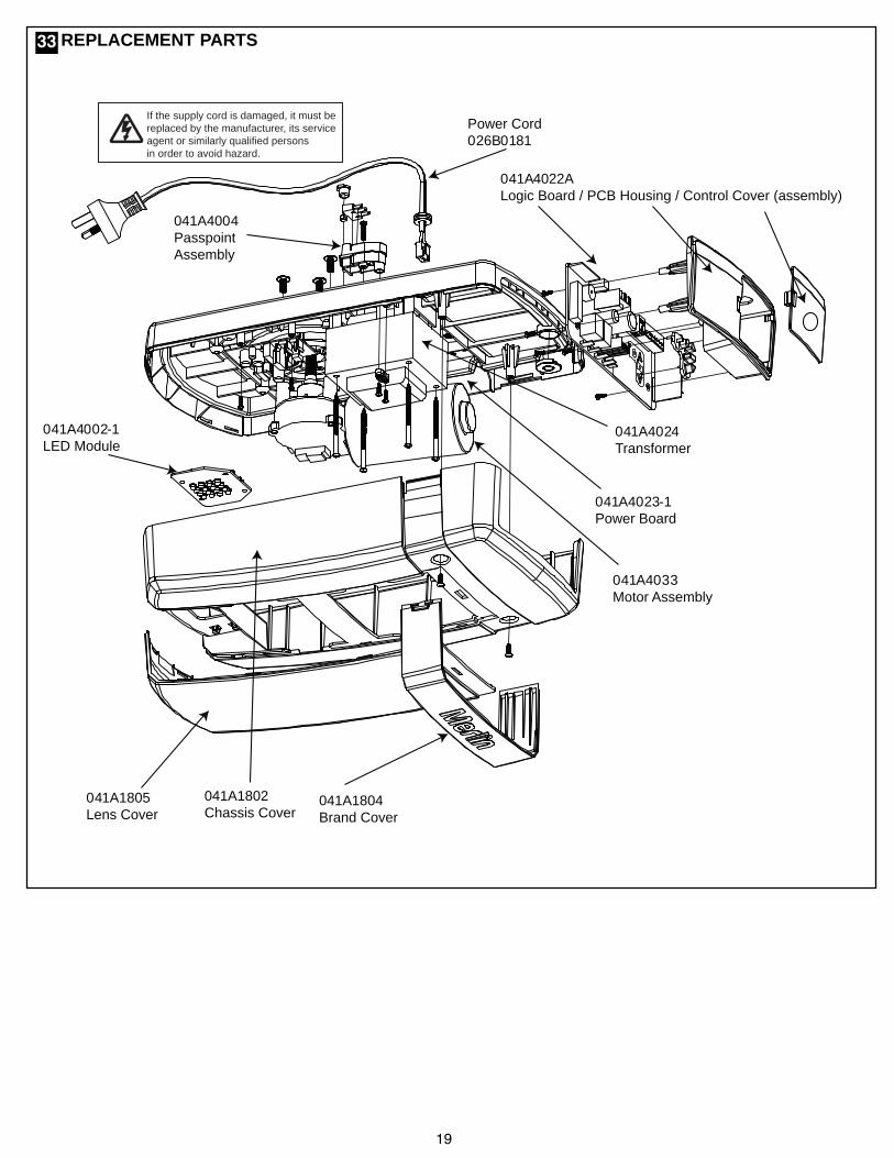
REPLACEMENT PARTS
If the supply cord is damaged, it must bereplaced by the manufacturer, its serviceagent or similarly qualified personsin order to avoid hazard.
Power Cord026B0181
041A4004PasspointAssembly
041A4024Transformer
041A4022ALogic Board / PCB Housing / Control Cover (assembly)
041A4002-1LED Module
041A1805Lens Cover
041A4033Motor Assembly
041A4023-1Power Board
041A1804Brand Cover
041A1802Chassis Cover
33

20
TROUBLE SHOOTING
7. Door opens but won't close:
• Check The Protector System™ (if you have installedthis accessory). If the light on the Beams are flashing,correct the alignment.• If opener light does not flash and it is a new installation,repeat Programming the Travel Limits.
Repeat the safety reverse test after the adjustment iscomplete.
8. Opener strains:
Door may be unbalanced or springs are broken. Closedoor and use manual release rope and handle todisconnect trolley. Open and close door manually. Aproperly balanced door will stay in any point of travelwhile being supported entirely by its springs. If it doesnot, call for professional garage door service to correctthe problem.
9. Opener hums briefly, then won't work:
• Garage door springs are broken. SEE ABOVE.• If problem occurs on first operation of opener, door islocked. Disable door lock.
Repeat safety reverse test after adjustment is complete.
10. Opener won't activate due to power failure:
• Pull manual release rope and handle down once todisconnect trolley. Door can be opened and closedmanually. When the power is restored, press the“GREEN” button in the centre of the trolley assembly.The next time the opener is activated, the trolley will re-connect.• The Outside Quick Release accessory (if fitted)disconnects the trolley from outside the garage in caseof power failure.
11. The Up and DOWN arrows on the control panelare flashing in sequence:
Check the diagnostic code on next page.
1. Opener doesn't operate from either door control orremote:
• Does the opener have electric power? Plug lamp intooutlet. If it doesn't light, check the fuse box or the circuitbreaker. (Some outlets are controlled by a wall switch.)• Have you disengaged all door locks? Review installationinstruction warnings on page 1.• Is there a build-up of ice or snow under door? The doormay be frozen to ground. Remove any obstruction.• The garage door spring may be broken. Have itreplaced.
2. Door operates from door control but not fromremote:
• Replace batteries in the remote if necessary.• If you have two or more remotes and only one operates,review Program Your Opener, Remote and KeylessEntry.
3. Remote has short range:
• Check the battery in the remote is fully charged.• Change the location of the remote control in the car.• A metal garage door, foil-backed insulation or metalsiding will reduce the transmission range.
4. Door reverses for no apparent reason and openerlight flashes 10 times:
• Check The Protector System™ (if you have installed thisaccessory). If the light is flashing, correct alignment.
If the Protector SystemTM is installed and needs to beremoved, the Opener will need to be reprogrammed asfollows:
• Remove the IR Beam wiring from the Opener• Turn the power OFF for 5 seconds• Turn the power ON for 5 seconds• Again turn the power OFF for 5 seconds• Turn the power back on and test the opener for normaloperation.
5. The garage door opens and closes by itself:
Make sure remote push button is not stuck "on".
6. Door stops but doesn't close completely:
Repeat Programming the Travel Limits.Repeat safety reverse test after any adjustment of doorarm length, close force or down limit adjustments.
34

21
DIAGNOSTIC CHART
Your garage door opener is programmed with self-diagnostic capabilities. The UP and DOWN arrows on the garage opener flash the diagnosticcodes.
DIAGNOSTIC CODE
UP Arrow DOWN ArrowFlash(es) Flash(es)
1 1
1 2
1 3
1 4
1 5
1 6
2 1-5
2 6
3 2
3 3
4 1-4
4 5
4 6
5 1-5
SYMPTOM
The garage door opener will notclose and the courtesy light flashes.
The garage door opener will notclose and the courtesy light flashes.
The door control will not function.
The garage door opener will notclose and the courtesy light flashes.
There is no door movement or veryslight.
Door continues to move after themotor stops.
Opener fails to operate.
Unable to set travel limit downdirection. Passpoint has not beenrecognised during programming.
Unable to set the travel or retainposition.
The battery status LED* is constantlyflashing green.
Door is moving stops and orreverses.
Opener runs approximately 150 mmto 200 mm, stops and reverses.
The garage door opener will notclose and the courtesy light flashes.
Door fails to operate or operateserractically. External accessorywiring failure.
POSSIBLE RESOLUTION
Safety sensors are not installed, connected or wires may be cut. Inspectsensor wires for a disconnected or cut wire.
There is a short or reversed wire for the safety sensors. Inspect safety sensorwire at all staple points and connection points and replace wire or correct asneeded.
The wires for the door control are shorted or the door control is faulty. Inspectsafety sensor wire at all staple points and connection points and replace wireor correct as needed.
Safety sensors are misaligned or were momentarily obstructed. Realign bothsensors to ensure both LEDs are steady and not flickering. Make sure nothingis hanging or mounted on the door that would interrupt the sensors path whileclosing.
No RPM pulses have been detected. Check the door manually for balance,binding or obstructions. Internally the possible cause may be the motor, logicboard or travel module. Try resetting door travel limits. Contact service centre.
RPM pulses have been detected after motor has turned off. Possible brokenspring. Check the door is correctly balanced and not creeping up or down.Contact a door service centre.
Possible logic board failure. Reboot opener by turning the mains power OFFand then ON after 15 seconds. Reprogram the door travel limits and forcesettings. Contact service centre.
Check the passpoint module has been activated by the belt Position Tab,during the door travel. Reset the travel limits.
Check travel module for proper assembly, replace if necessary.
Battery backup charging circuit error, replace logic board. *(if applicable)
Manually open and close the door. Check for binding or obstructions, such asa broken spring or door lock. If the door is binding or sticking contact a traineddoor systems technician. If door is not binding or sticking attempt to reprogramtravel (refer to page 24 ).
Communication error to travel module. Check travel module connections,replace module if necessary.
Safety sensors are misaligned or were momentarily obstructed. Realign bothsensors to ensure both LEDs are steady and not flickering. Make sure nothingis hanging or mounted on the door that would interrupt the sensor's path whileclosing.
Check the external wiring to the control panel terminal is wired correctly. Turnoff power, remove all external wiring, and retest door operation.
35

22
Input Voltage...........230-240 Vac, 50 HzMax. Pull Force ......600 NPower .....................150 WattStandby Power .......0.8 Watt (door fully closed)Normal Torque ........5 NmMax door weight......70 kgs Spring balancedMax door area.........Sectional door 13.5 m2
MotorType........................DC gearmotor permanent lubricationNoise level ..............54 db at 1 metre
Drive MechanismDrive .......................Belt with one-piece trolley on
steel rail.Length of Travel......Adjustable to 3.0 mLED light .................25 Watt equivalent
Door Linkage ..........Adjustable door arm. Pull cord trolley release.SafetyPersonal .................Push button stop in UP and DOWN direction. Automatic safety reverse in both UP and DOWN
direction.Electronic................Automatic force adjustmentElectrical .................Transformer overload protector and low voltage push button wiring.Limit Device ............Mechanical Passpoint/RPM sensorLimit Adjustment .....ElectronicSoft-start/Soft-stopDimensionsLength (Overall).......3.24 mHeadroom Required 30 mmHanging Weight .......11 kg
ReceiverMemory Registers ...64 handset codes
4 keypad devices - 1 code each
OperatingFrequency.................433.30/433.92/434.54 MHz
SPECIFICATIONS - PowerAce - MT60EVO36

23114D4643A © 2013, The Chamberlain Group Inc.
TM Trademark of The Chamberlain Group, Inc.® Registered Trademark of The Chamberlain Group, Inc.
CHAMBERLAIN LIMITED WARRANTYMerlin Professional MT60EVO PowerAceSectional Garage Door Opener
Chamberlain Australia Pty Limited / Chamberlain New Zealand Limited(Chamberlain), the manufacturer of Merlin® automatic garage dooropeners, is committed to manufacturing and supplying high quality goods.As part of this commitment, we seek to provide reliable service andsupport for our goods and are pleased to provide you, the originalpurchaser, with this Chamberlain Limited Warranty.
We also provide the following statement as required by the AustralianConsumer Law: In Australia, in addition to your rights under thisChamberlain Limited Warranty, our goods come with guarantees thatcannot be excluded under the Australian Consumer Law. You are entitledto a replacement or refund for a major failure and for compensation forany other reasonably foreseeable loss or damage. You are also entitledto have the goods repaired or replaced if the goods fail to be ofacceptable quality and the failure does not amount to a major failure.
Chamberlain’s warrantyChamberlain warrants to the original purchaser of the Merlin® MT60EVOSectional Door Opener (Unit) that all parts of the Unit, other than remotecontrolled transmitters and accessories, globes and batteries, are freefrom defects in materials and workmanship for a period of 24 months or5,000 cycles (opening & closing of the garage door) whichever comesfirst, from the date of purchase when installed in a residential premisewith a residential specified garage door that is designed for the solepurpose of domestic domicile. Chamberlain warrants that remotecontrolled transmitters and accessories included with the Unit are freefrom defects in materials and workmanship for a period of 12 months fromthe date of purchase.
Batteries and globes are not covered under the Chamberlain LimitedWarranty.
It is a condition of this Chamberlain Limited Warranty that the Unit is sold,installed and serviced by a Professional Dealer appointed byChamberlain. A Merlin® branded garage door opener purchased over theinternet and installed by a person other than a Professional Dealer will notbe covered by this Chamberlain Limited Warranty.
During the applicable Chamberlain Limited Warranty period, if you areconcerned that the Unit may be defective, for prompt on-site service callthe Professional Dealer that sold/installed the opener, or our servicecentre on the toll free number below and a Chamberlain technician willdiagnose the problem and arrange for this to be rectified. Once theproblem has been diagnosed, subject to your rights under the AustralianConsumer Law with respect to major failures, Chamberlain or itsProfessional Dealer will provide you with:1. repairs to the Unitor2. a replacement Unit.
Repairs and replacement parts provided under this Chamberlain LimitedWarranty are provided free of charge and are warranted for the remainingportion of the original warranty period.
This Chamberlain Limited Warranty provides benefits which are in additionto your other rights and remedies as a consumer.
ExclusionsIf our service centre determines that a warranty claim has been made inrespect of a failure or defect arising under or out of any exclusion detailedbelow such that the claim is not covered under this Chamberlain LimitedWarranty, we may, subject to your other rights and remedies as aconsumer, charge you a fee to repair, replace and/or return the Unit toyou.This Chamberlain Limited Warranty does not cover any failure of, ordefect in, the Unit due to:
1 non-compliance with the instructions regarding installation, operation,maintenance and testing of the Unit or of any product with which the Unitis used;
2 any attempt by a person other than a Professional Dealer to repair,dismantle, reinstall or move the Unit to another location once it has beeninstalled;3 tampering, neglect, abuse, wear and tear, accident, electrical storm,excessive use or conditions other than normal domestic use;4 problems with, or relating to, the garage door or garage doorhardware, including but not limited to the door springs, door rollers, dooralignment or hinges;5 problems caused by electrical faults or replacement of batteries orlight bulbs;6 water or moisture ingress that causes corrosion or electricalmalfunction;7 corrosion caused by sea air if located near a waterway, beach etc; or8 fitment to a commercial door or in a commercial operating application.
NB: A General Purpose Outlet (GPO) ie: power point must be supplied bythe consumer as this electrical fitting does not form a part of the Unit(opener).
If this Chamberlain Limited Warranty does not apply, you may have rightsavailable to you under the Australian Consumer Law.
Liability – Australia onlyExcept as set out in the Australian Consumer Law (being Schedule 2 ofthe Competition and Consumer Act 2010) (as amended, consolidated orreplaced):1 all other guarantees, warranties and representations in relation to theUnit or its supply are excluded to the extent that Chamberlain canlawfully exclude them; and2 under no circumstances will Chamberlain be liable for consequential,incidental or special damages arising in connection with the use, orinability to use, the Unit, other than those which were reasonablyforeseeable as liable to result from the failure.
Liability – New Zealand onlyExcept as set out in the Fair Trading Act 1986 and the ConsumerGuarantees Act 1993 (as amended, consolidated or replaced):1 all other guarantees, warranties and representations in relation to theUnit or its supply are excluded to the extent that Chamberlain canlawfully exclude them; and2 under no circumstances will Chamberlain be liable for consequential,incidental or special damages arising in connection with the use, orinability to use, the Unit, other than those which were reasonablyforeseeable as liable to result from the failure.
NoteWe request that you retain your sales docket or invoice as proof-of-purchase and attach it to this manual to enable you to establish the dateof purchase in the unlikely event of a warranty service being required.Chamberlain reserves the right to change the design and specificationsof the Unit without prior notification. Some features or accessories of theUnit may not be available in certain markets or areas. Please check withyour distributor.
Chamberlain service centre contact details
AustraliaPhone toll free 1800 638 234Fax toll free 1800 888 121Chamberlain Australia Pty. Ltd.PO BOX 1446Lane Cove NSW 1595Website: gomerlin.com.au
New ZealandAuckland phone 09 477 2823Phone toll free 0800 653 667Fax toll free 0800 653 663Website: gomerlin.co.nz
Email: [email protected]