Embed Size (px)
Citation preview
Chapter.7: Oscillators
• Objectives:
– To understand
• The basic operation of an Oscillator
• the working of low frequency oscillators
–RC phase shift oscillator
–Wien bridge Oscillator
• the working of tuned oscillator
– Colpitt’s Oscillator, Hartley Oscillator
– Crystal Oscillator
• the working of UJT Oscillator
Basic operation of an Oscillator
• An amplifier with positive feedback results in oscillations if the following conditions
are satisfied:
– The loop gain ( product of the gain of the amplifier and the gain of the
feedback network) is unity
– The total phase shift in the loop is 0°
• If the output signal is sinusoidal, such a circuit is referred to as sinusoidal
oscillator.
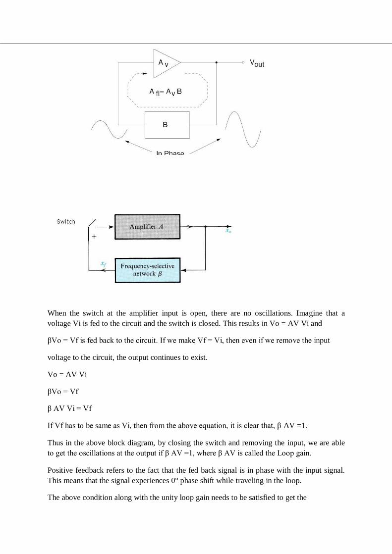
When the switch at the amplifier input is open, there are no oscillations. Imagine that a
voltage Vi is fed to the circuit and the switch is closed. This results in Vo = AV Vi and
βVo = Vf is fed back to the circuit. If we make Vf = Vi, then even if we remove the input
voltage to the circuit, the output continues to exist.
Vo = AV Vi
βVo = Vf
β AV Vi = Vf
If Vf has to be same as Vi, then from the above equation, it is clear that, β AV =1.
Thus in the above block diagram, by closing the switch and removing the input, we are able
to get the oscillations at the output if β AV =1, where β AV is called the Loop gain.
Positive feedback refers to the fact that the fed back signal is in phase with the input signal.
This means that the signal experiences 0° phase shift while traveling in the loop.
The above condition along with the unity loop gain needs to be satisfied to get the
sustained oscillations. These conditions are referred to as ‘Barkhausen criterion’. Another
way of seeing how the feedback circuit provides operation as an oscillator is obtained by
noting the denominator in the basic equation
Af = A / (1+βA).
When βA = -1 or magnitude 1 at a phase angle of 180°, the denominator becomes 0 and
the gain with feedback Af becomes infinite.Thus, an infinitesimal signal ( noise voltage)
can provide a measurable output voltage, and the circuit acts as an oscillator even without
an input signal.
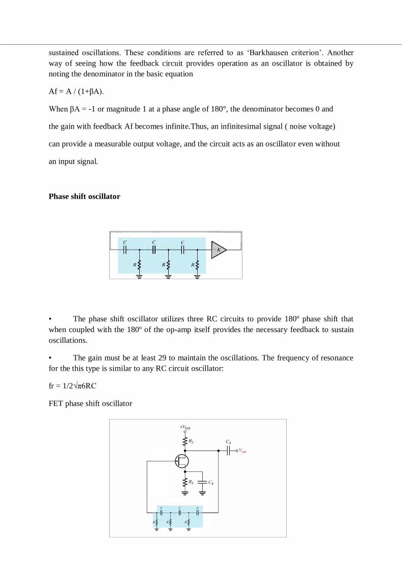
Phase shift oscillator
• The phase shift oscillator utilizes three RC circuits to provide 180º phase shift that
when coupled with the 180º of the op-amp itself provides the necessary feedback to sustain
oscillations.
• The gain must be at least 29 to maintain the oscillations. The frequency of resonance
for the this type is similar to any RC circuit oscillator:
fr = 1/2√π6RC
FET phase shift oscillator
101
• The amplifier stage is self biased with a capacitor bypassed source resistor Rs and a
drain bias resistor RD . The FET device parameters of interest are gm and rd.
• |A| = gmRL, where RL = (RDrd / RD + rd)
• At the operating frequency, we can assume that the input impedance of the
amplifier is infinite.
• This is a valid approximation provided, the oscillator operating frequency is low
enough so that FET capacitive impedances can be neglected.
• The output impedance of the amplifier stage given by RL should also be small
compared to the impedance seen looking into the feedback network so that no attenuation due
to loading occurs.
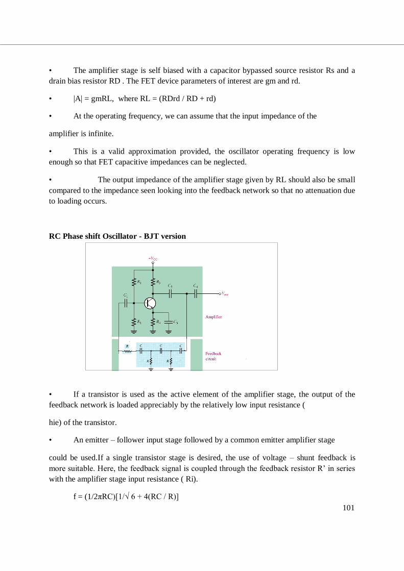
RC Phase shift Oscillator - BJT version
• If a transistor is used as the active element of the amplifier stage, the output of the
feedback network is loaded appreciably by the relatively low input resistance (
hie) of the transistor.
• An emitter – follower input stage followed by a common emitter amplifier stage
could be used.If a single transistor stage is desired, the use of voltage – shunt feedback is
more suitable. Here, the feedback signal is coupled through the feedback resistor R’ in series
with the amplifier stage input resistance ( Ri).
f = (1/2πRC)[1/√ 6 + 4(RC / R)]
102
hfe > 23 + 29 (R/RC) + 4 (RC / R)
Problem:
It is desired to design a phase shift oscillator using an FET having gm = 5000µS, rd =
40 kΩ , and a feedback circuit value of R = 10 kΩ. Select the value of C for oscillator
operation at 5 kHz and RD for A > 29 to ensure oscillator action.
Solution:
• f = 1/2√π6RC ; C = 1/2√π6Rf = 1.3nF
• |A| = gm RL
Let A = 40; RL = |A| / gm = 8 kΩ
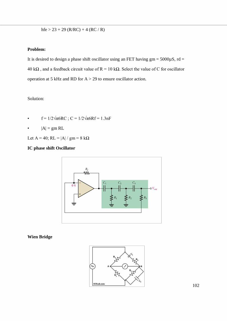
IC phase shift Oscillator
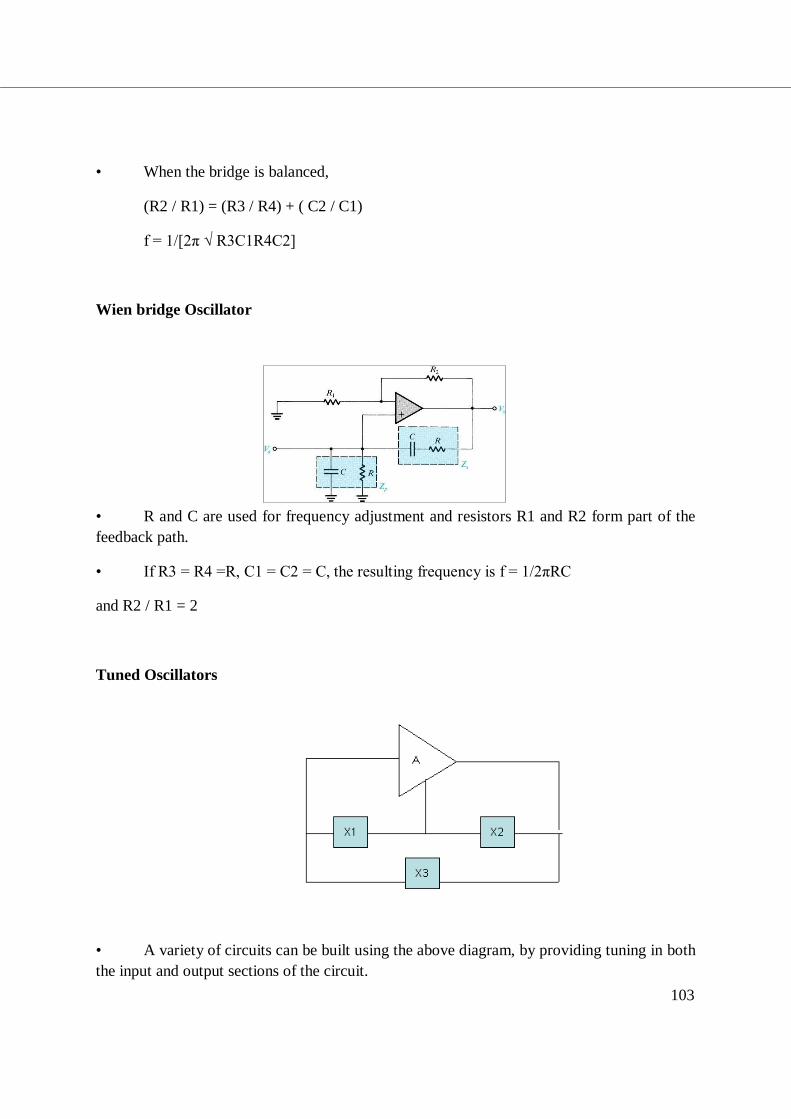
Wien Bridge
103
• When the bridge is balanced,
(R2 / R1) = (R3 / R4) + ( C2 / C1)
f = 1/[2π √ R3C1R4C2]
Wien bridge Oscillator
• R and C are used for frequency adjustment and resistors R1 and R2 form part of the
feedback path.
• If R3 = R4 =R, C1 = C2 = C, the resulting frequency is f = 1/2πRC
and R2 / R1 = 2
Tuned Oscillators
• A variety of circuits can be built using the above diagram, by providing tuning in both
the input and output sections of the circuit.
104
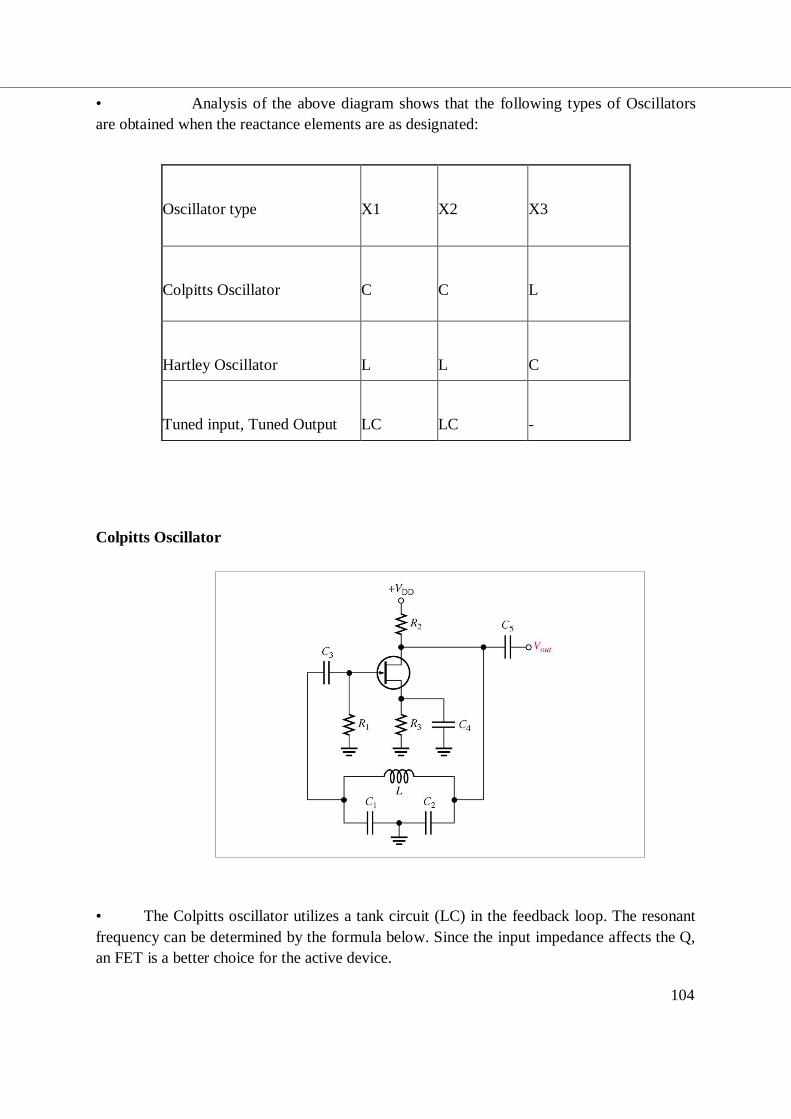
• Analysis of the above diagram shows that the following types of Oscillators
are obtained when the reactance elements are as designated:
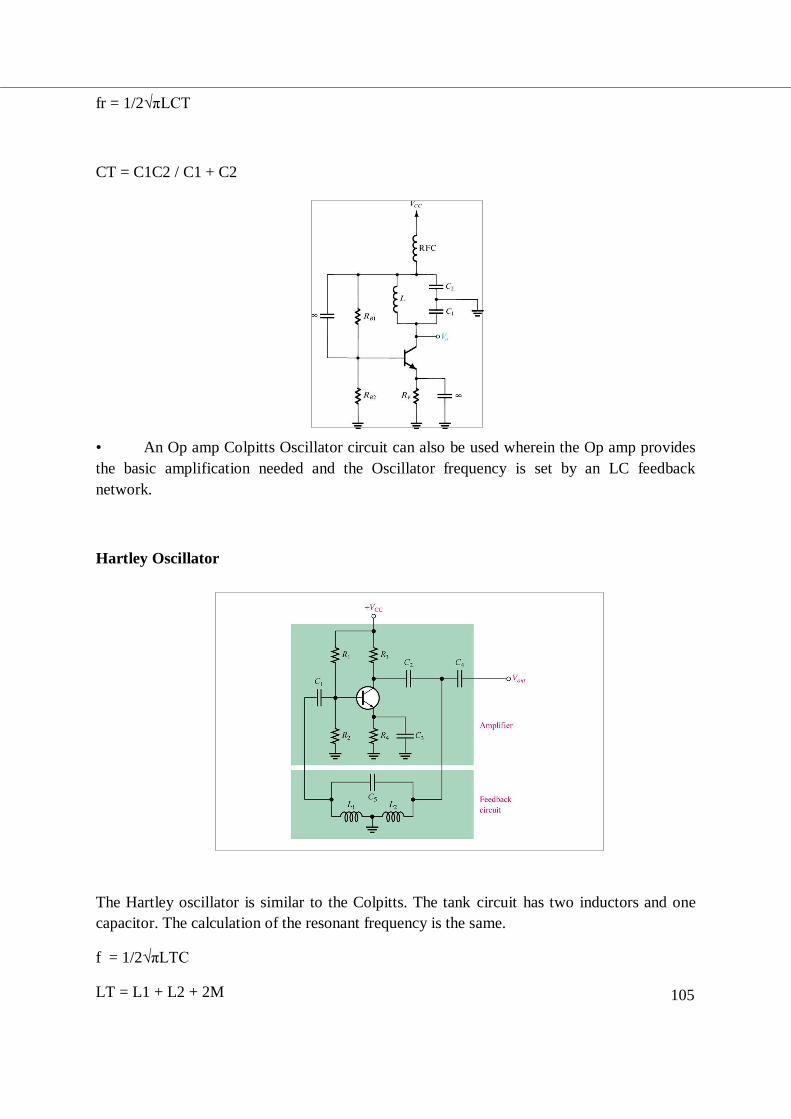
Colpitts Oscillator
• The Colpitts oscillator utilizes a tank circuit (LC) in the feedback loop. The resonant
frequency can be determined by the formula below. Since the input impedance affects the Q,
an FET is a better choice for the active device.
Oscillator type
X1
X2
X3
Colpitts Oscillator
C
C
L
Hartley Oscillator
L
L
C
Tuned input, Tuned Output
LC
LC
-
105
fr = 1/2√πLCT
CT = C1C2 / C1 + C2
• An Op amp Colpitts Oscillator circuit can also be used wherein the Op amp provides
the basic amplification needed and the Oscillator frequency is set by an LC feedback
network.
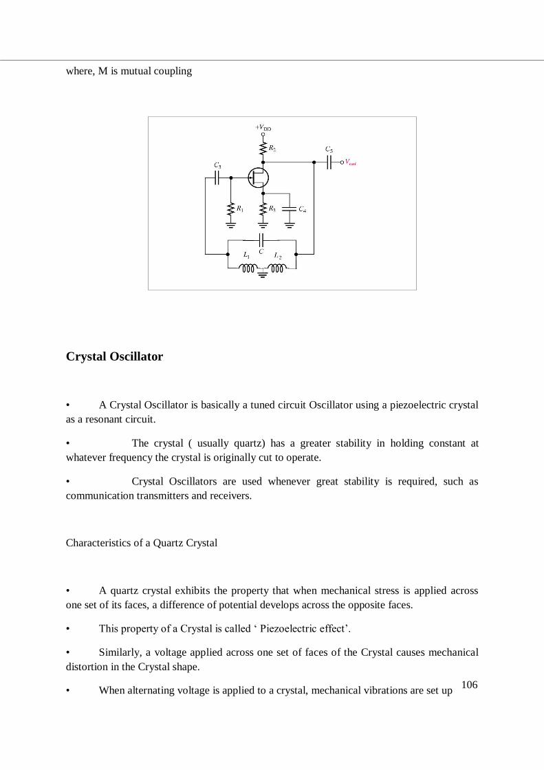
Hartley Oscillator
The Hartley oscillator is similar to the Colpitts. The tank circuit has two inductors and one
capacitor. The calculation of the resonant frequency is the same.
f = 1/2√πLTC
LT = L1 + L2 + 2M
106
where, M is mutual coupling
Crystal Oscillator
• A Crystal Oscillator is basically a tuned circuit Oscillator using a piezoelectric crystal
as a resonant circuit.
• The crystal ( usually quartz) has a greater stability in holding constant at
whatever frequency the crystal is originally cut to operate.
• Crystal Oscillators are used whenever great stability is required, such as
communication transmitters and receivers.
Characteristics of a Quartz Crystal
• A quartz crystal exhibits the property that when mechanical stress is applied across
one set of its faces, a difference of potential develops across the opposite faces.
• This property of a Crystal is called ‘ Piezoelectric effect’.
• Similarly, a voltage applied across one set of faces of the Crystal causes mechanical
distortion in the Crystal shape.
• When alternating voltage is applied to a crystal, mechanical vibrations are set up
107
– these vibrations having a natural resonant frequency dependent on the Crystal.
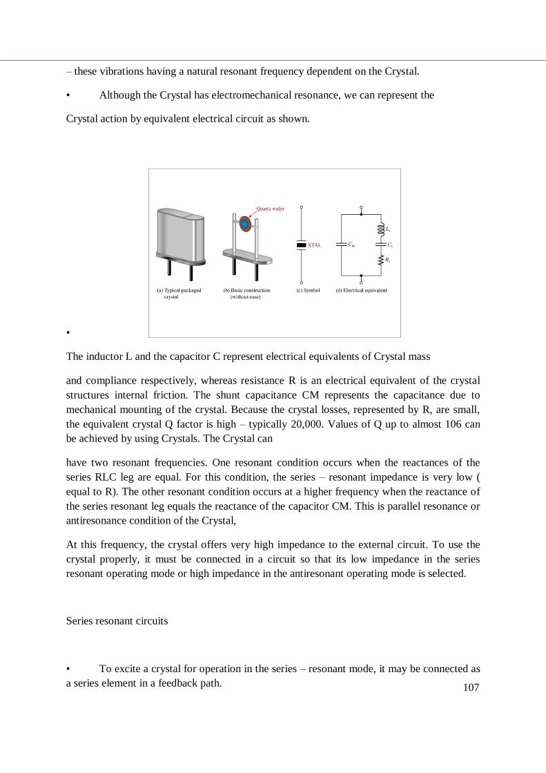
• Although the Crystal has electromechanical resonance, we can represent the
Crystal action by equivalent electrical circuit as shown.
•
The inductor L and the capacitor C represent electrical equivalents of Crystal mass
and compliance respectively, whereas resistance R is an electrical equivalent of the crystal
structures internal friction. The shunt capacitance CM represents the capacitance due to
mechanical mounting of the crystal. Because the crystal losses, represented by R, are small,
the equivalent crystal Q factor is high – typically 20,000. Values of Q up to almost 106 can
be achieved by using Crystals. The Crystal can
have two resonant frequencies. One resonant condition occurs when the reactances of the
series RLC leg are equal. For this condition, the series – resonant impedance is very low (
equal to R). The other resonant condition occurs at a higher frequency when the reactance of
the series resonant leg equals the reactance of the capacitor CM. This is parallel resonance or
antiresonance condition of the Crystal,
At this frequency, the crystal offers very high impedance to the external circuit. To use the
crystal properly, it must be connected in a circuit so that its low impedance in the series
resonant operating mode or high impedance in the antiresonant operating mode is selected.
Series resonant circuits
• To excite a crystal for operation in the series – resonant mode, it may be connected as
a series element in a feedback path.
108
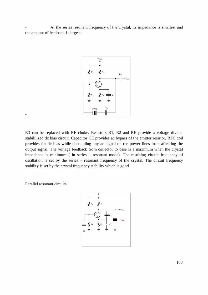
• At the series resonant frequency of the crystal, its impedance is smallest and
the amount of feedback is largest.
•
R3 can be replaced with RF choke. Resistors R1, R2 and RE provide a voltage divider
stabililized dc bias circuit. Capacitor CE provides ac bypass of the emitter resistor, RFC coil
provides for dc bias while decoupling any ac signal on the power lines from affecting the
output signal. The voltage feedback from collector to base is a maximum when the crystal
impedance is minimum ( in series – resonant mode). The resulting circuit frequency of
oscillation is set by the series – resonant frequency of the crystal. The circuit frequency
stability is set by the crystal frequency stability which is good.
Parallel resonant circuits
109
Since the parallel resonant impedance of a crystal is a maximum value, it is connected in
shunt. The circuit is similar to a Colpitts circuit with Crystal connected as inductor element.
Maximum voltage is developed across the crystal at its parallel resonant frequency. The
voltage is coupled to the emitter by a capacitor voltage divider capacitors C1 and C2.
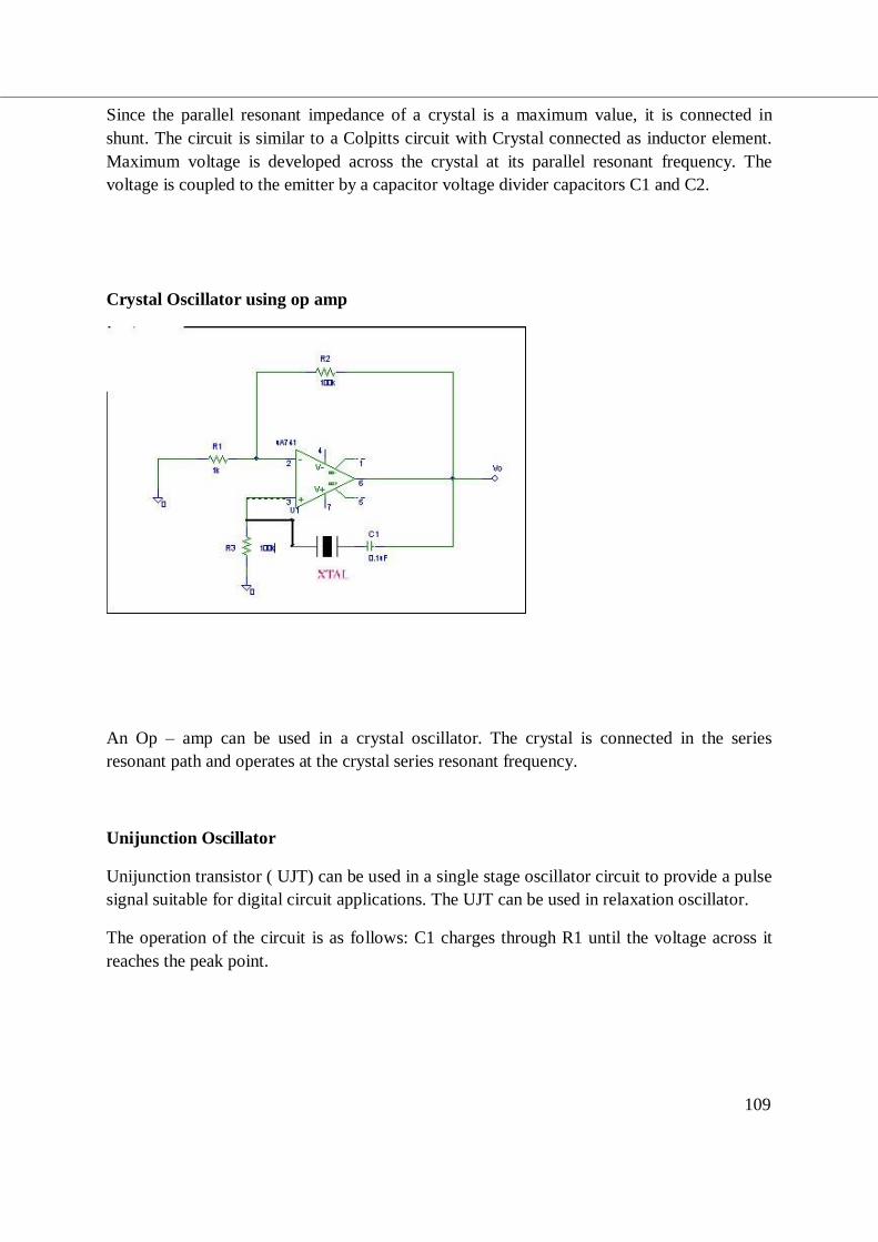
Crystal Oscillator using op amp
An Op – amp can be used in a crystal oscillator. The crystal is connected in the series
resonant path and operates at the crystal series resonant frequency.
Unijunction Oscillator
Unijunction transistor ( UJT) can be used in a single stage oscillator circuit to provide a pulse
signal suitable for digital circuit applications. The UJT can be used in relaxation oscillator.
The operation of the circuit is as follows: C1 charges through R1 until the voltage across it
reaches the peak point.
111
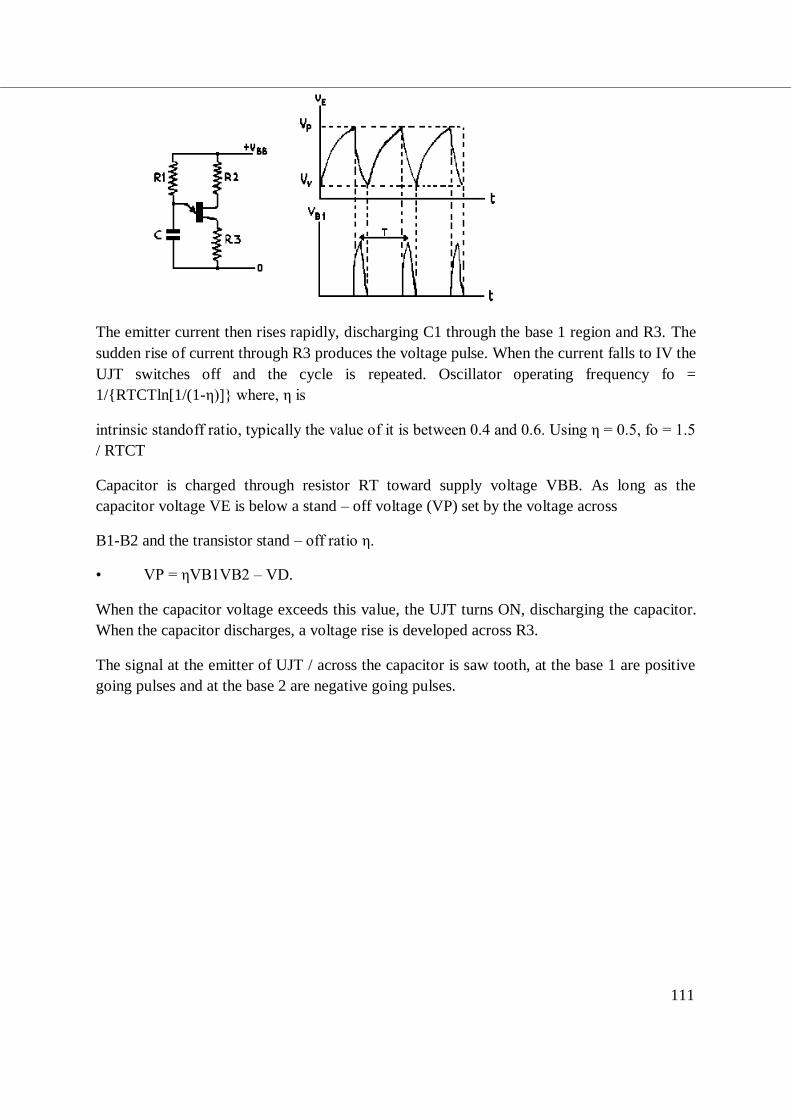
The emitter current then rises rapidly, discharging C1 through the base 1 region and R3. The
sudden rise of current through R3 produces the voltage pulse. When the current falls to IV the
UJT switches off and the cycle is repeated. Oscillator operating frequency fo =
1/RTCTln[1/(1-η)] where, η is
intrinsic standoff ratio, typically the value of it is between 0.4 and 0.6. Using η = 0.5, fo = 1.5
/ RTCT
Capacitor is charged through resistor RT toward supply voltage VBB. As long as the
capacitor voltage VE is below a stand – off voltage (VP) set by the voltage across
B1-B2 and the transistor stand – off ratio η.
• VP = ηVB1VB2 – VD.
When the capacitor voltage exceeds this value, the UJT turns ON, discharging the capacitor.
When the capacitor discharges, a voltage rise is developed across R3.
The signal at the emitter of UJT / across the capacitor is saw tooth, at the base 1 are positive
going pulses and at the base 2 are negative going pulses.
112
Summary:
• Phase shift Oscillator, f = 1/2πRC√6 , β = 1/29
• Wien bridge Oscillator f = 1/2πRC
• Colpitts Oscillator, f = 1/2π √LCeq
• Ceq = C1C2/(C1+C2)
• Hartley Oscillator, f = 1/2π √LeqC
• Leq = L1+L2+2M
• UJT Oscillator: f = 1/RTCTln[1/(1-η)]