Embed Size (px)
Citation preview
PESIT Bangalore South Campus Hosur road, 1km before Electronic City, Bengaluru -100
Department of Electronics & Communication Engineering
QUESTION PAPER
INTERNAL ASSESSMENT TEST 2
Date : 4/10/2016 Marks: 40 Subject & Code: BASIC ELECTRICAL ENGINEERING -15ELE15 Sec : F,G,H,I,J,K
Name of faculty : Dhanashree Bhate, Hema B , Prashanth V Time : 8:30 a.m. – 10 a.m.
Note: Answer FIVE full questions, selecting any ONE full question from each part. Marks
PART 1
1
With neat diagram explain the construction of DC machine. Explain the parts of the machine.
08
2 Derive the emf equation of a DC generator and explain the term armature
reaction.
08
PART 2
3 A shunt generator delivers 50 kW at 250 V and runs at 400 RPM. The armature and field resistances are 0.02 Ω and 50 Ω respectively. Calculate the speed of the
machine running as shunt motor and taking 50kW input at 250 V. Allow 1 Volt per brush contact drop.
08
4 A DC shunt motor runs at 1000 RPM on 200V supply. Ra = 0.8 Ω. The current
taken is 40 A in addition to field current. What resistance do you connect in series with the armature to reduce speed to 600 RPM, the current in armature
remaining same.
08
PART 3
5 Prove that power consumed in an RL circuit is VI cos . Draw the waveforms and relevant vector diagram.
08
6 Prove that power consumed in a pure capacitor is zero. Draw the wavefo rms and relevant vector diagram.
08
PART 4
7 Two circuits with impedances Z1= (10 +j15) Ω and Z2= (6 - j8 ) Ω are
connected in parallel. If the supply current is 20 A . Calculate branch currents. What is the power dissipated in each branch. Draw the vector diagram showing
the source current, branch currents.
08
8 In a RLC series circuit R=10 Ω, L=0.1 H and C= 200 µF. If the applied voltage is 200V at a frequency of 50 Hz. Find impedance, current , power factor & power.
08
PART 5
9 With neat diagram explain the construction and working of dynamometer type wattmeter.
08
10 With neat diagram explain the construction and working of a single phase induction type energy meter
08
PESIT Bangalore South Campus Hosur road, 1km before Electronic City, Bengaluru -100
Department of Electronics & Communication Engineering
SCHEME AND SOLUTION INTERNAL TEST-II
Subject & Code : Basic Electrical Engineering, 15ELE15 Semester: I Section: F,G,H,I,J,K
Name of faculty: Dhanashree Bhate
Q.No Marks
1.
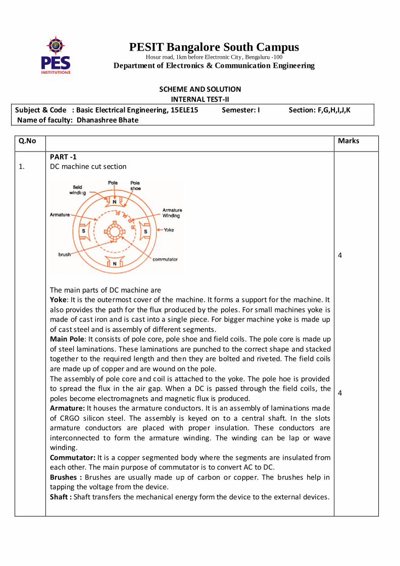
PART -1 DC machine cut section
The main parts of DC machine are Yoke: It is the outermost cover of the machine. It forms a support for the machine. It
also provides the path for the flux produced by the poles. For small machines yoke is made of cast iron and is cast into a single piece. For bigger machine yoke is made up
of cast steel and is assembly of different segments. Main Pole: It consists of pole core, pole shoe and field coils. The pole core is made up
of steel laminations. These laminations are punched to the correct shape and stacked together to the required length and then they are bolted and riveted. The field coils
are made up of copper and are wound on the pole. The assembly of pole core and coil is attached to the yoke. The pole hoe is provided to spread the flux in the air gap. When a DC is passed through the field coils, the poles become electromagnets and magnetic flux is produced. Armature: It houses the armature conductors. It is an assembly of laminations made of CRGO silicon steel. The assembly is keyed on to a central shaft. In the slots armature conductors are placed with proper insulation. These conductors are
interconnected to form the armature winding. The winding can be lap or wave winding.
Commutator: It is a copper segmented body where the segments are insulated from each other. The main purpose of commutator is to convert AC to DC.
Brushes : Brushes are usually made up of carbon or copper. The brushes help in tapping the voltage from the device.
Shaft : Shaft transfers the mechanical energy form the device to the external devices.
4
4
PESIT Bangalore South Campus Hosur road, 1km before Electronic City, Bengaluru -100
Department of Electronics & Communication Engineering
2.
Derive the emf equation of a DC generator and explain the term armature reaction.
Let P = the number of poles
= flux per pole in wb Z = total number of armature conductors
N= Speed of rotation of armature RPM A= number of parallel paths in the armature winding A=P for LAP A= 2 for WAVE Time taken for 1 revolution = 60/N seconds
In one revolution a conductor crosses P poles and cuts a flux of P webber According to Faraday’s law Average emf induced in each conductor = flux cut / time taken
= P / 60/N
= N P /60 Emf of generator equals emf per parallel path and in each path Z /A conductors are in
series E = N P Z/( 60 A)
E = Z N P / (60A) Armature reaction : The armature consists of number of armature conductors. These conductors form armature winding. When the current is flowing through the armature conductors these current carrying conductors will have magnetic field around them. This magnetic field will oppose the field developed by the main poles. The resultant of this is the demagnetizing effect and the effective magnetic field in the air gap reduces. This is called armature reaction.
5
3
PESIT Bangalore South Campus Hosur road, 1km before Electronic City, Bengaluru -100
Department of Electronics & Communication Engineering
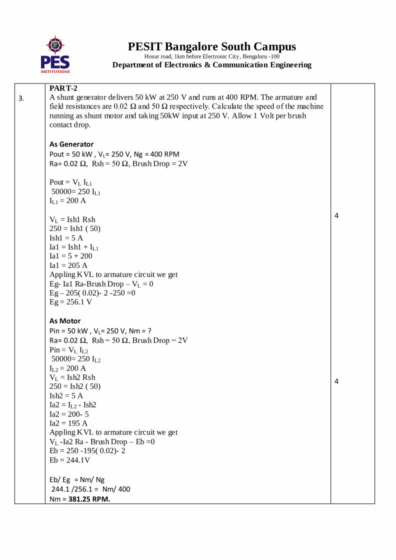
3.
PART-2
A shunt generator delivers 50 kW at 250 V and runs at 400 RPM. The armature and field resistances are 0.02 Ω and 50 Ω respectively. Calculate the speed of the machine
running as shunt motor and taking 50kW input at 250 V. Allow 1 Volt per brush contact drop. As Generator Pout = 50 kW , VL= 250 V, Ng = 400 RPM Ra= 0.02 Ω, Rsh = 50 Ω, Brush Drop = 2V
Pout = VL IL1
50000= 250 IL1 IL1 = 200 A VL = Ish1 Rsh 250 = Ish1 ( 50)
Ish1 = 5 A Ia1 = Ish1 + IL1
Ia1 = 5 + 200
Ia1 = 205 A Appling KVL to armature circuit we get
Eg- Ia1 Ra-Brush Drop – VL = 0 Eg – 205( 0.02)- 2 -250 =0 Eg = 256.1 V
As Motor
Pin = 50 kW , VL= 250 V, Nm = ? Ra= 0.02 Ω, Rsh = 50 Ω, Brush Drop = 2V
Pin = VL IL2 50000= 250 IL2
IL2 = 200 A VL = Ish2 Rsh 250 = Ish2 ( 50)
Ish2 = 5 A Ia2 = IL2 - Ish2
Ia2 = 200- 5 Ia2 = 195 A Appling KVL to armature circuit we get
VL -Ia2 Ra - Brush Drop – Eb =0 Eb = 250 -195( 0.02)- 2
Eb = 244.1V
Eb/ Eg = Nm/ Ng 244.1 /256.1 = Nm/ 400
Nm = 381.25 RPM.
4
4
PESIT Bangalore South Campus Hosur road, 1km before Electronic City, Bengaluru -100
Department of Electronics & Communication Engineering
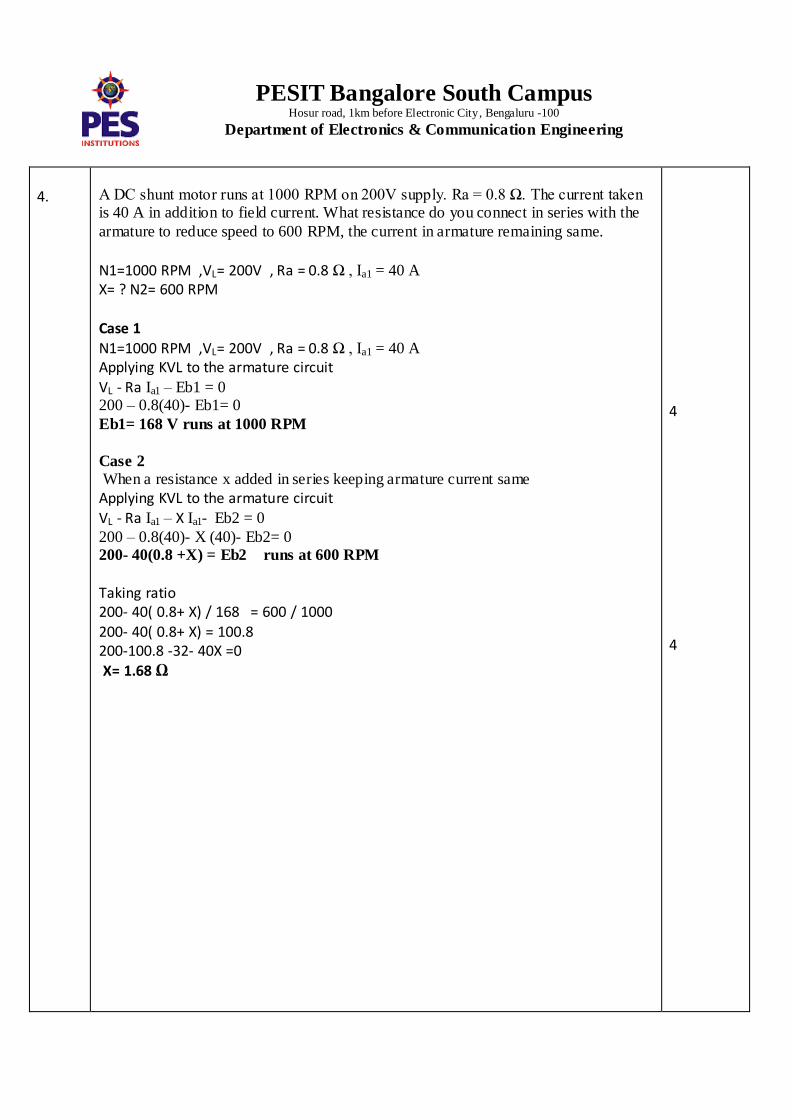
4.
A DC shunt motor runs at 1000 RPM on 200V supply. Ra = 0.8 Ω. The current taken is 40 A in addition to field current. What resistance do you connect in series with the
armature to reduce speed to 600 RPM, the current in armature remaining same. N1=1000 RPM ,VL= 200V , Ra = 0.8 Ω , Ia1 = 40 A X= ? N2= 600 RPM
Case 1
N1=1000 RPM ,VL= 200V , Ra = 0.8 Ω , Ia1 = 40 A Applying KVL to the armature circuit
VL - Ra Ia1 – Eb1 = 0 200 – 0.8(40)- Eb1= 0
Eb1= 168 V runs at 1000 RPM
Case 2 When a resistance x added in series keeping armature current same
Applying KVL to the armature circuit VL - Ra Ia1 – X Ia1- Eb2 = 0
200 – 0.8(40)- X (40)- Eb2= 0 200- 40(0.8 +X) = Eb2 runs at 600 RPM
Taking ratio 200- 40( 0.8+ X) / 168 = 600 / 1000 200- 40( 0.8+ X) = 100.8 200-100.8 -32- 40X =0 X= 1.68 Ω
4
4
PESIT Bangalore South Campus Hosur road, 1km before Electronic City, Bengaluru -100
Department of Electronics & Communication Engineering
5.
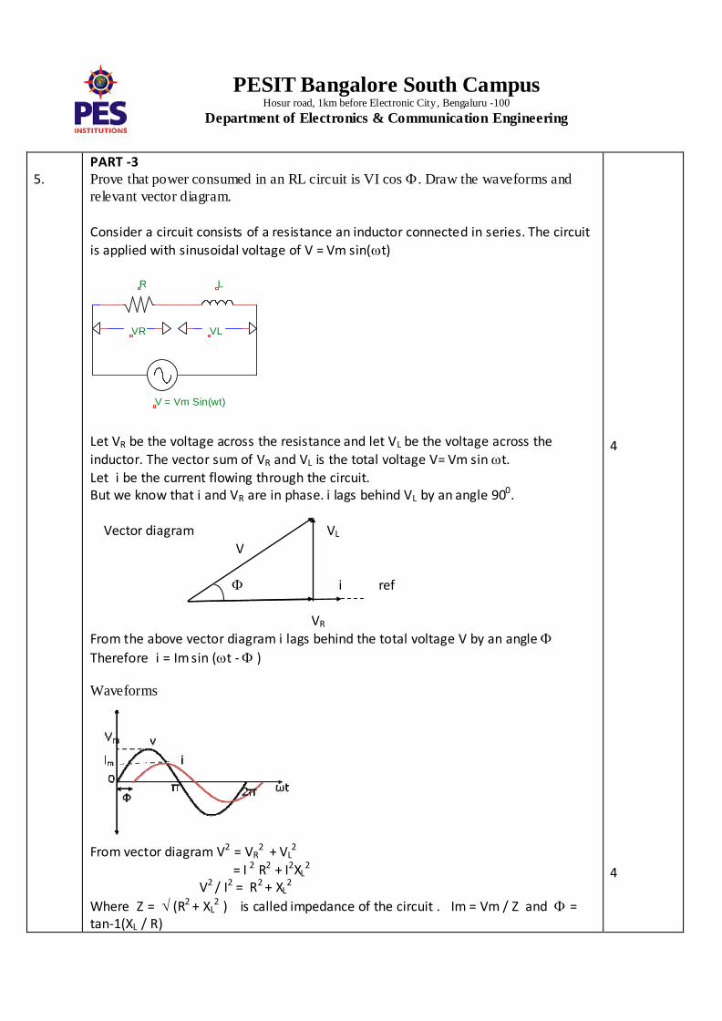
PART -3 Prove that power consumed in an RL circuit is VI cos . Draw the waveforms and
relevant vector diagram.
Consider a circuit consists of a resistance an inductor connected in series. The circuit
is applied with sinusoidal voltage of V = Vm sin(t)
Let VR be the voltage across the resistance and let VL be the voltage across the
inductor. The vector sum of VR and VL is the total voltage V= Vm sin t. Let i be the current flowing through the circuit. But we know that i and VR are in phase. i lags behind VL by an angle 900. Vector diagram VL V
i ref
VR From the above vector diagram i lags behind the total voltage V by an angle
Therefore i = Im sin (t - ) Waveforms
From vector diagram V2 = VR
2 + VL
2
= I 2 R2 + I2XL2
V2 / I2 = R2 + XL2
Where Z = (R2 + XL2 ) is called impedance of the circuit . Im = Vm / Z and =
tan-1(XL / R)
4
4
VR VL
LR
V = Vm Sin(wt)
PESIT Bangalore South Campus Hosur road, 1km before Electronic City, Bengaluru -100
Department of Electronics & Communication Engineering
6.
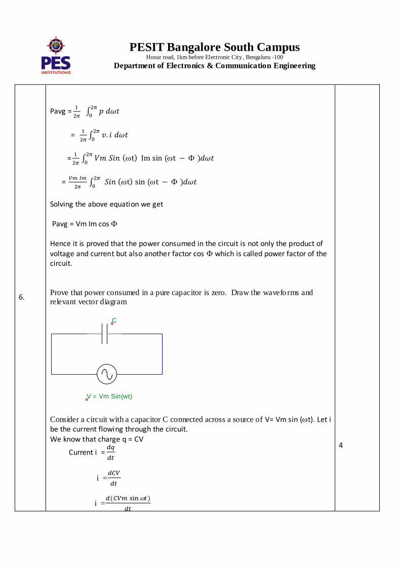
Pavg =
=
=
=
Solving the above equation we get
Pavg = Vm Im cos
Hence it is proved that the power consumed in the circuit is not only the product of
voltage and current but also another factor cos which is called power factor of the circuit.
Prove that power consumed in a pure capacitor is zero. Draw the wavefo rms and relevant vector diagram
Consider a circuit with a capacitor C connected across a source of V= Vm sin (t). Let i be the current flowing through the circuit.
We know that charge q = CV
Current i =
i =
i =
4
V = Vm Sin(wt)
C
PESIT Bangalore South Campus Hosur road, 1km before Electronic City, Bengaluru -100
Department of Electronics & Communication Engineering
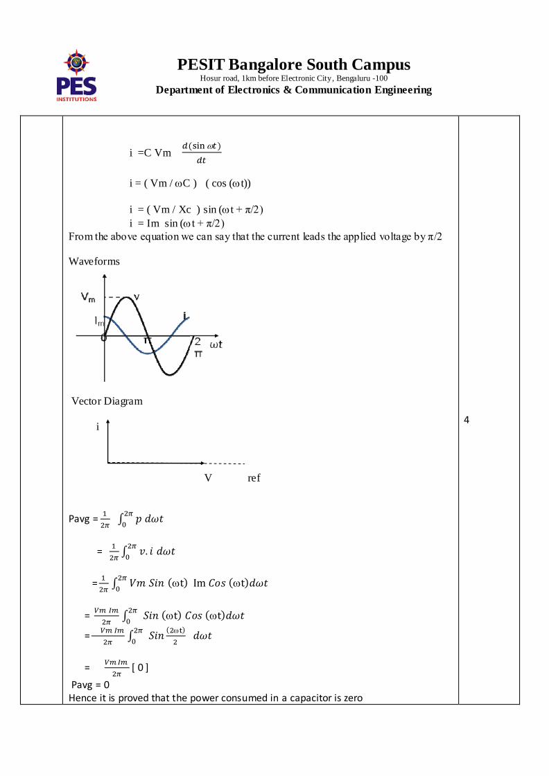
i =C Vm
i = ( Vm / C ) ( cos (t))
i = ( Vm / Xc ) sin (t + π/2)
i = Im sin (t + π/2)
From the above equation we can say that the current leads the applied voltage by π/2 Waveforms
Vector Diagram
i
V ref
Pavg =
=
=
=
=
=
[ 0 ]
Pavg = 0 Hence it is proved that the power consumed in a capacitor is zero
4
PESIT Bangalore South Campus Hosur road, 1km before Electronic City, Bengaluru -100
Department of Electronics & Communication Engineering
7.
PART-4
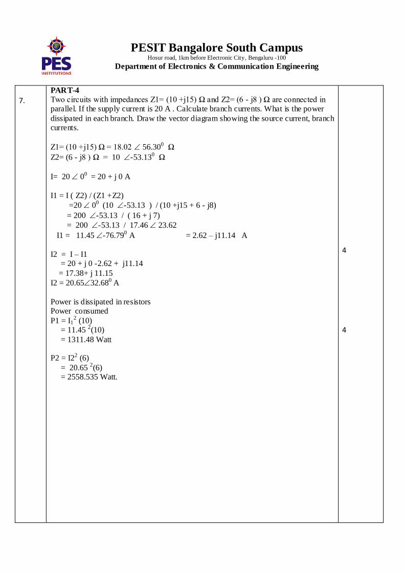
Two circuits with impedances Z1= (10 +j15) Ω and Z2= (6 - j8 ) Ω are connected in parallel. If the supply current is 20 A . Calculate branch currents. What is the power
dissipated in each branch. Draw the vector diagram showing the source current, branch currents.
Z1= (10 +j15) Ω = 18.02 56.300 Ω
Z2= (6 - j8 ) Ω = 10 -53.130 Ω
I= 20 00 = 20 + j 0 A
I1 = I ( Z2) / (Z1 +Z2)
=20 00 (10 -53.13 ) / (10 +j15 + 6 - j8)
= 200 -53.13 / ( 16 + j 7)
= 200 -53.13 / 17.46 23.62
I1 = 11.45 -76.790 A = 2.62 – j11.14 A
I2 = I – I1 = 20 + j 0 -2.62 + j11.14
= 17.38+ j 11.15
I2 = 20.6532.680 A
Power is dissipated in resistors Power consumed
P1 = I12 (10)
= 11.45 2(10)
= 1311.48 Watt P2 = I22 (6)
= 20.65 2(6) = 2558.535 Watt.
4
4
PESIT Bangalore South Campus Hosur road, 1km before Electronic City, Bengaluru -100
Department of Electronics & Communication Engineering
8.
In a RLC series circuit R=10 Ω, L=0.1 H and C= 200 µF. If the applied voltage is 200V at a frequency of 50 Hz. Find impedance, current, power factor & power.
R=10 Ω, L=0.1 H and C= 200 µF
XL = 2 π f L = 2 (3.14 ) 50 (0.1) = 31.4 Ω
Xc = 1/ 2 π f C
= 1/ 2(3.14) 50( 200x10-6) = 15.92 Ω
Z= ( R2 + (XL – Xc )2 )
= ( 102 + (31.4 – 15.92 )2 )
Z = 18.43 Ω
I = V/Z = 200 / 18.43
I = 10.85 A
= –
= –
= 57.13 0
Power Factor = cos
= cos (57.13) Pf = 0.542 lag
Power = V I cos = 200 ( 10.85) 0.542
Power = 1177.48 Watt
4
4
PESIT Bangalore South Campus Hosur road, 1km before Electronic City, Bengaluru -100
Department of Electronics & Communication Engineering
9.
PART-5
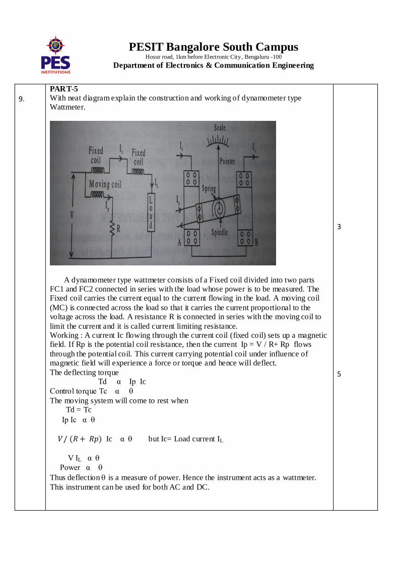
With neat diagram explain the construction and working of dynamometer type Wattmeter.
A dynamometer type wattmeter consists of a Fixed coil divided into two parts FC1 and FC2 connected in series with the load whose power is to be measured. The Fixed coil carries the current equal to the current flowing in the load. A moving coil
(MC) is connected across the load so that it carries the current proportional to the voltage across the load. A resistance R is connected in series with the moving coil to
limit the current and it is called current limiting resistance. Working : A current Ic flowing through the current coil (fixed coil) sets up a magnetic field. If Rp is the potential coil resistance, then the current Ip = V / R+ Rp flows
through the potential coil. This current carrying potential coil under influence of magnetic field will experience a force or torque and hence will deflect.
The deflecting torque Td α Ip Ic
Control torque Tc α
The moving system will come to rest when Td = Tc
Ip Ic α
Ic α but Ic= Load current IL
V IL α
Power α
Thus deflection is a measure of power. Hence the instrument acts as a wattmeter.
This instrument can be used for both AC and DC.
3
5
PESIT Bangalore South Campus Hosur road, 1km before Electronic City, Bengaluru -100
Department of Electronics & Communication Engineering
10.
With neat diagram explain the construction and working of a single phase induction type energy meter.
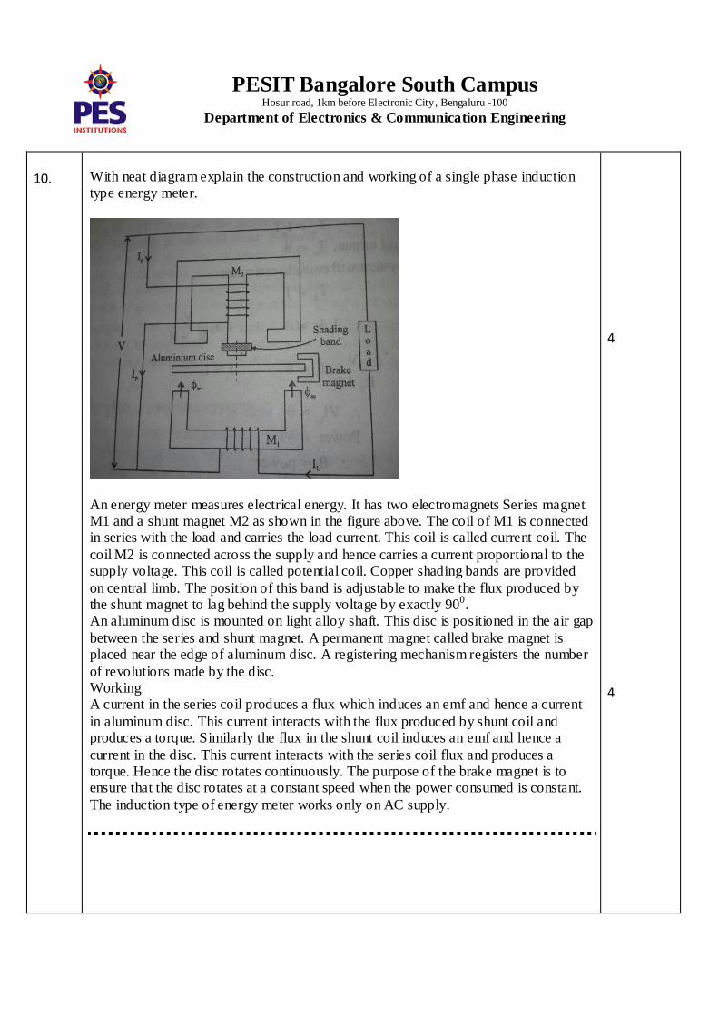
An energy meter measures electrical energy. It has two electromagnets Series magnet M1 and a shunt magnet M2 as shown in the figure above. The coil of M1 is connected in series with the load and carries the load current. This coil is called current coil. The
coil M2 is connected across the supply and hence carries a current proportional to the supply voltage. This coil is called potential coil. Copper shading bands are provided
on central limb. The position of this band is adjustable to make the flux produced by the shunt magnet to lag behind the supply voltage by exactly 900. An aluminum disc is mounted on light alloy shaft. This disc is positioned in the air gap
between the series and shunt magnet. A permanent magnet called brake magnet is placed near the edge of aluminum disc. A registering mechanism registers the number
of revolutions made by the disc. Working A current in the series coil produces a flux which induces an emf and hence a current
in aluminum disc. This current interacts with the flux produced by shunt coil and produces a torque. Similarly the flux in the shunt coil induces an emf and hence a
current in the disc. This current interacts with the series coil flux and produces a torque. Hence the disc rotates continuously. The purpose of the brake magnet is to ensure that the disc rotates at a constant speed when the power consumed is constant.
The induction type of energy meter works only on AC supply.
4
4

PESIT Bangalore South Campus Hosur road, 1km before Electronic City, Bengaluru -100
Department of Electronics & Communication Engineering

PESIT Bangalore South Campus Hosur road, 1km before Electronic City, Bengaluru -100
Department of Electronics & Communication Engineering