Embed Size (px)
Citation preview
MSE Wall Corrosion Monitoring Kit
Installation Guide
Materials & Tests Unit
Revision #3, 26 February 2018
The Materials and Tests Unit Chemical lab annually monitors and maintains corrosion data on 100 plus MSE walls throughout the state.
These installations provides crucial data and
research on the effects of backfill material and corrosion reaction to the supporting straps.
This guide will cover installation of the corrosion monitoring kit for both the Reinforced Earth Type, SINE Wall type and the Vista wall type MSE wall.
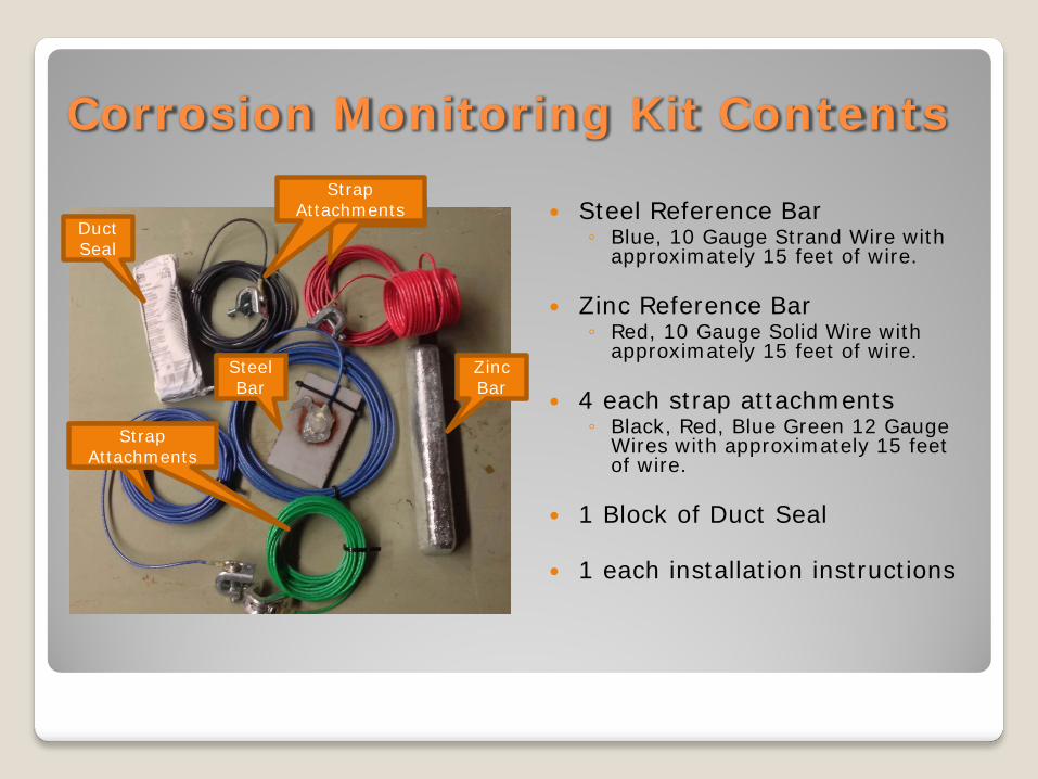
Corrosion Monitoring Kit Contents
Steel Reference Bar ◦ Blue, 10 Gauge Strand Wire with
approximately 15 feet of wire.
Zinc Reference Bar ◦ Red, 10 Gauge Solid Wire with
approximately 15 feet of wire.
4 each strap attachments ◦ Black, Red, Blue Green 12 Gauge
Wires with approximately 15 feet of wire.
1 Block of Duct Seal 1 each installation instructions
Zinc Bar
Steel Bar
Duct Seal
Strap Attachments
Strap Attachments
Installation Considerations In most cases, one corrosion monitoring kit
per bridge structure; unless the Engineer and or Geo-Technical Unit requests an additional monitoring kit to be installed.
For projects that utilizes the same quarry for
78 or 57 stone one corrosion monitoring kit will be installed per project.
If one or more additional quarries are utilized to obtain backfill material an additional monitoring kit will be placed per structure.
Installation Considerations For projects that utilize screened backfill one
corrosion monitoring kit will be placed on either side of the bridge structure.
For the use of screened backfill there are
additional sampling and testing requirements.
https://connect.ncdot.gov/resources/Materials/MaterialsResources/Mechanically Stabilized Earth Wall Fine Aggregate Sampling and Testing Procedures.pdf
Installation Considerations
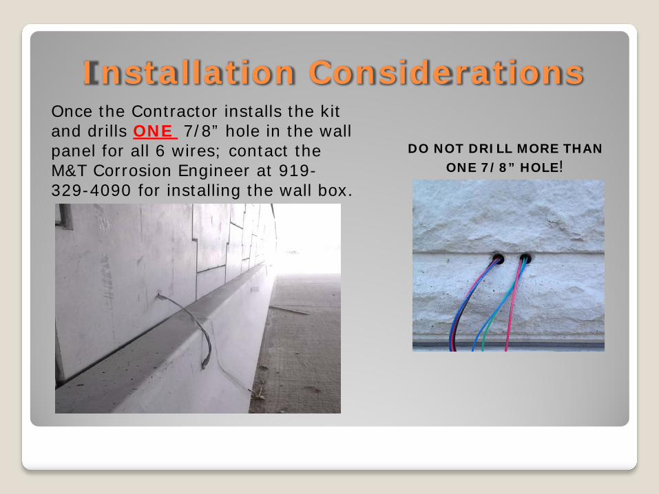
DO NOT DRILL MORE THAN ONE 7/8” HOLE!
Once the Contractor installs the kit and drills ONE 7/8” hole in the wall panel for all 6 wires; contact the M&T Corrosion Engineer at 919-329-4090 for installing the wall box.
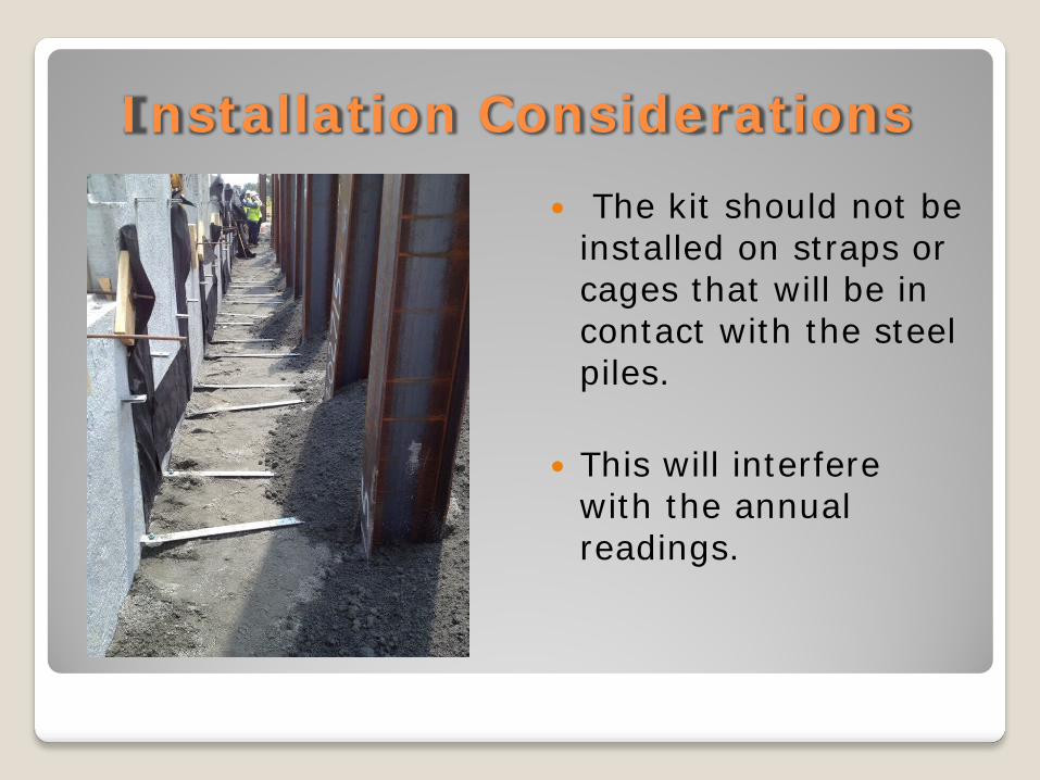
Installation Considerations The kit should not be
installed on straps or cages that will be in contact with the steel piles.
This will interfere
with the annual readings.
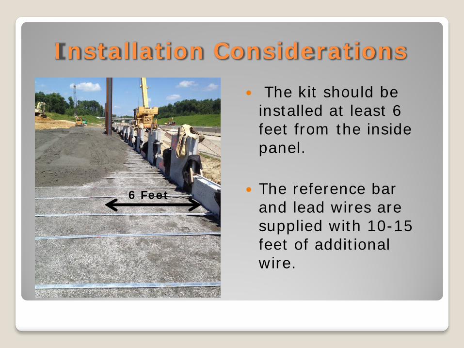
Installation Considerations The kit should be
installed at least 6 feet from the inside panel.
The reference bar
and lead wires are supplied with 10-15 feet of additional wire.
6 Feet
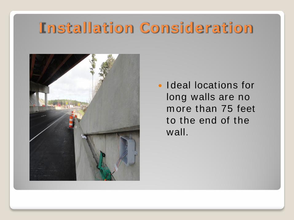
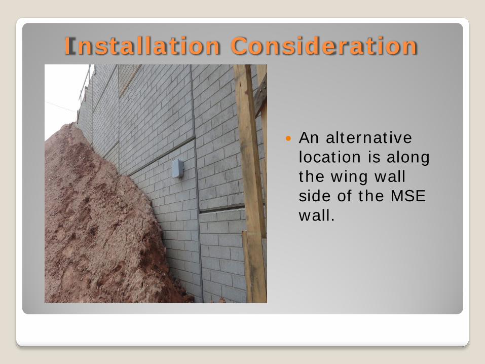
Installation Consideration
Ideal locations for long walls are no more than 75 feet to the end of the wall.
Installation Consideration
An alternative
location is along the wing wall side of the MSE wall.
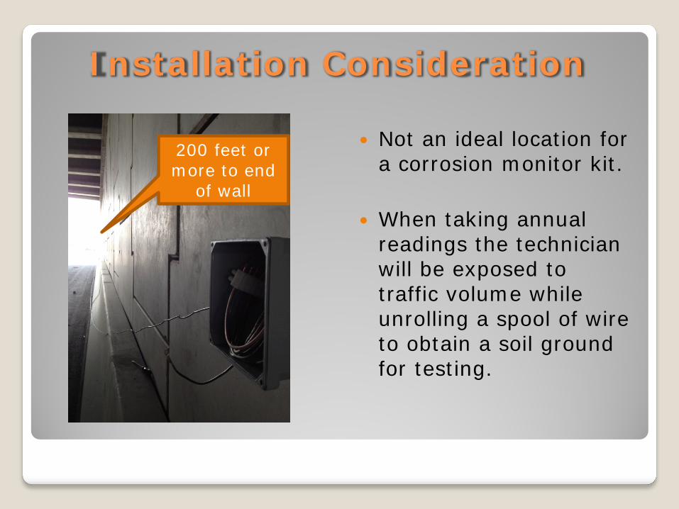
Installation Consideration
Not an ideal location for a corrosion monitor kit.
When taking annual
readings the technician will be exposed to traffic volume while unrolling a spool of wire to obtain a soil ground for testing.
200 feet or more to end
of wall
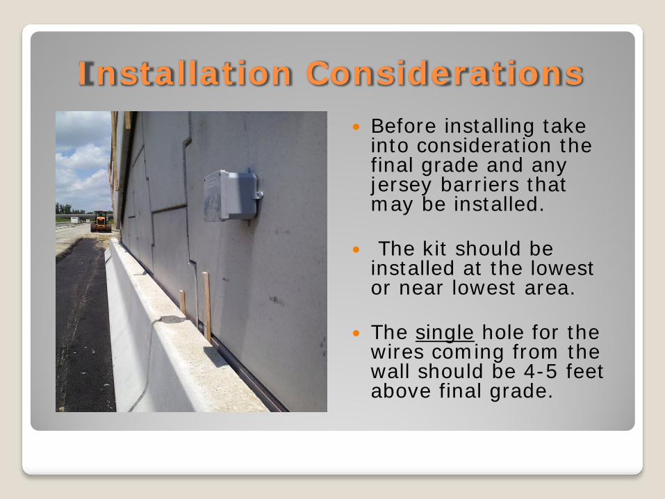
Installation Considerations Before installing take
into consideration the final grade and any jersey barriers that may be installed.
The kit should be
installed at the lowest or near lowest area.
The single hole for the
wires coming from the wall should be 4-5 feet above final grade.
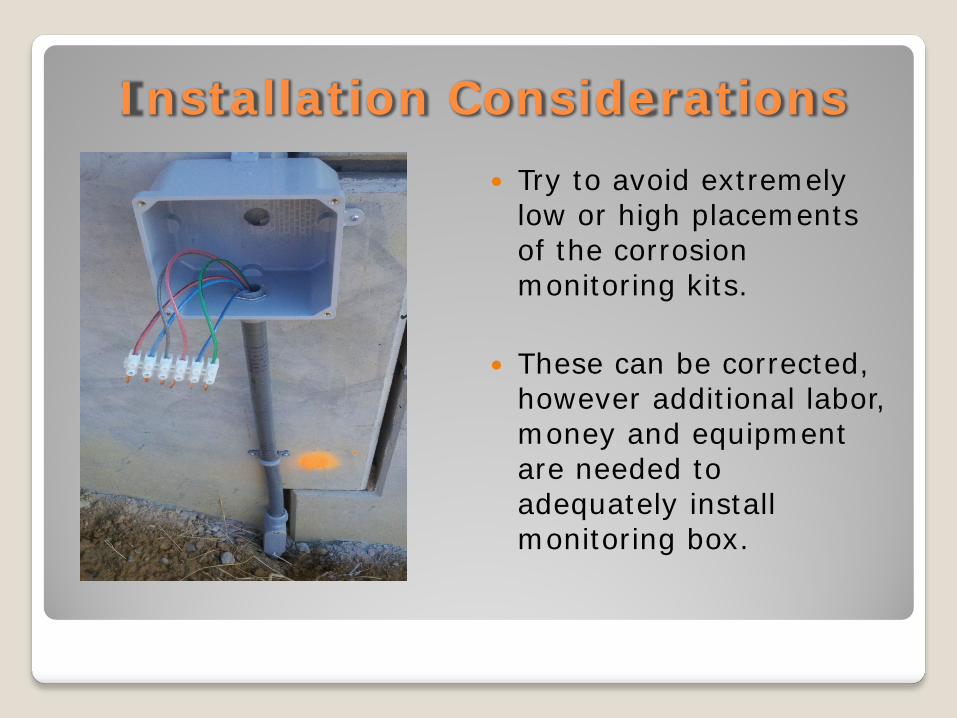
Installation Considerations Try to avoid extremely
low or high placements of the corrosion monitoring kits.
These can be corrected, however additional labor, money and equipment are needed to adequately install monitoring box.
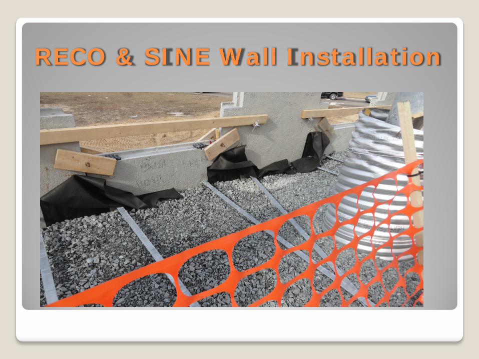
RECO & SINE Wall Installation
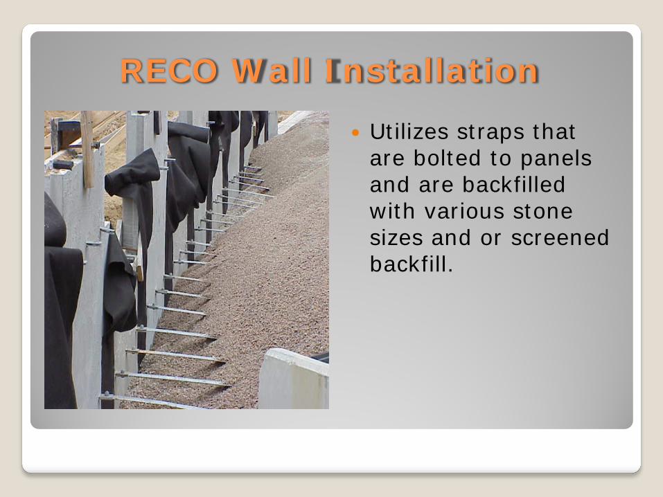
RECO Wall Installation
Utilizes straps that are bolted to panels and are backfilled with various stone sizes and or screened backfill.
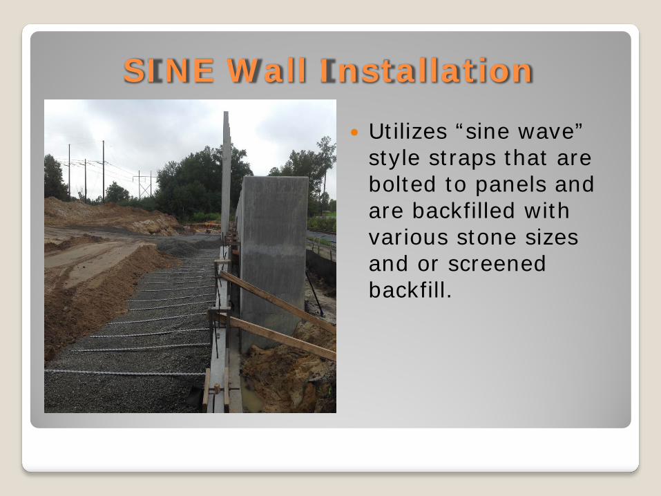
SINE Wall Installation
Utilizes “sine wave” style straps that are bolted to panels and are backfilled with various stone sizes and or screened backfill.

RECO & SINE Wall Installation For the use of screened
backfill there are additional sampling and testing requirements.
https://connect.ncdot.gov/resources/Materials/MaterialsResources/Mechanically Stabilized Earth Wall Fine Aggregate Sampling and Testing Procedures.pdf
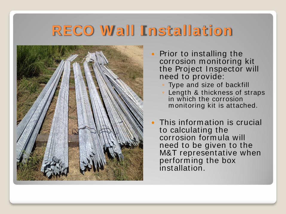
RECO Wall Installation Prior to installing the
corrosion monitoring kit the Project Inspector will need to provide: ◦ Type and size of backfill ◦ Length & thickness of straps
in which the corrosion monitoring kit is attached.
This information is crucial
to calculating the corrosion formula will need to be given to the M&T representative when performing the box installation.
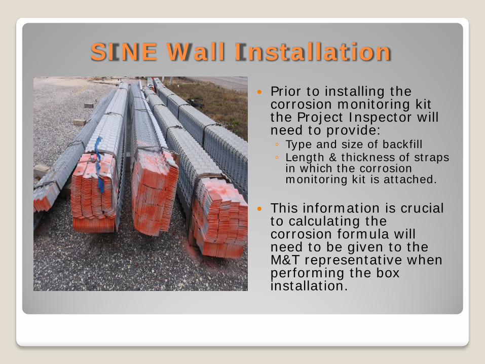
SINE Wall Installation Prior to installing the
corrosion monitoring kit the Project Inspector will need to provide: ◦ Type and size of backfill ◦ Length & thickness of straps
in which the corrosion monitoring kit is attached.
This information is crucial
to calculating the corrosion formula will need to be given to the M&T representative when performing the box installation.
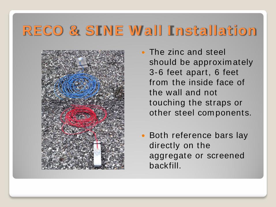
RECO & SINE Wall Installation The zinc and steel
should be approximately 3-6 feet apart, 6 feet from the inside face of the wall and not touching the straps or other steel components.
Both reference bars lay
directly on the aggregate or screened backfill.
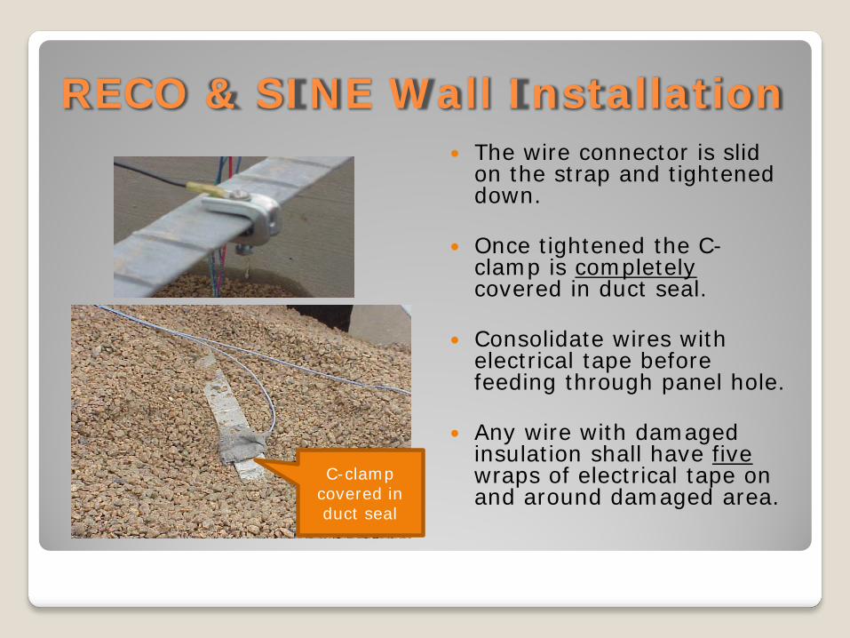
RECO & SINE Wall Installation The wire connector is slid
on the strap and tightened down.
Once tightened the C-
clamp is completely covered in duct seal.
Consolidate wires with
electrical tape before feeding through panel hole.
Any wire with damaged
insulation shall have five wraps of electrical tape on and around damaged area.
C-clamp covered in duct seal
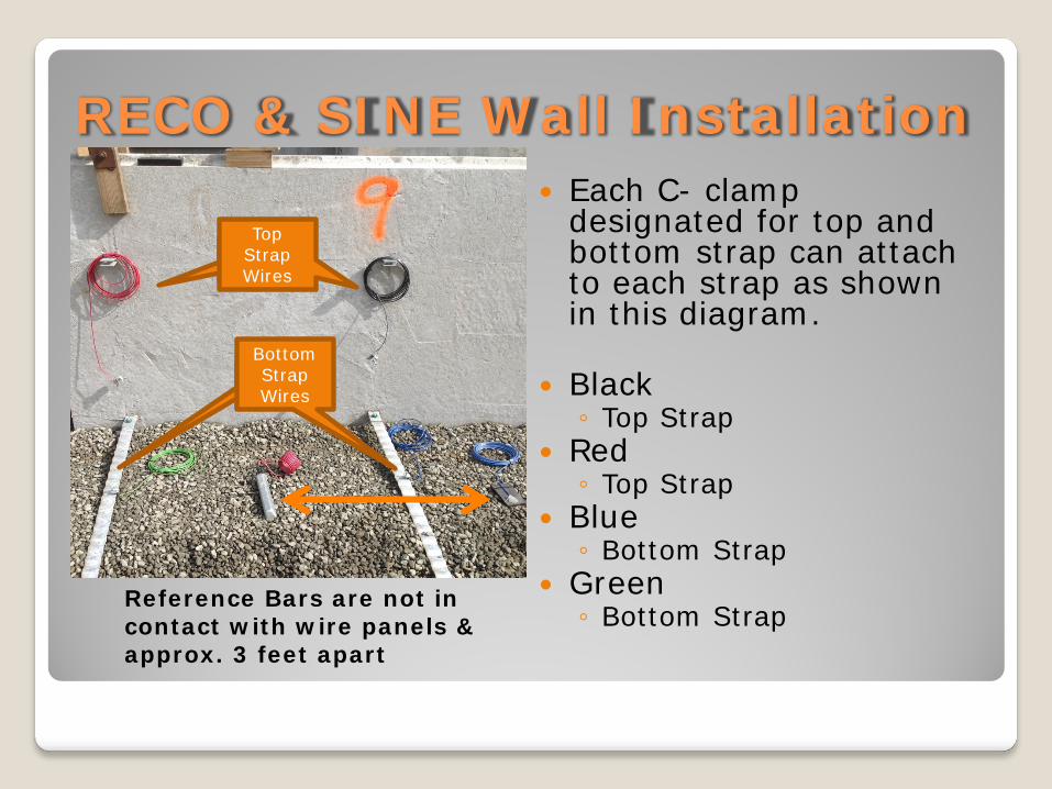
RECO & SINE Wall Installation Each C- clamp
designated for top and bottom strap can attach to each strap as shown in this diagram.
Black ◦ Top Strap
Red ◦ Top Strap
Blue ◦ Bottom Strap
Green ◦ Bottom Strap
Reference Bars are not in contact with wire panels & approx. 3 feet apart
Top Strap Wires
Bottom Strap Wires
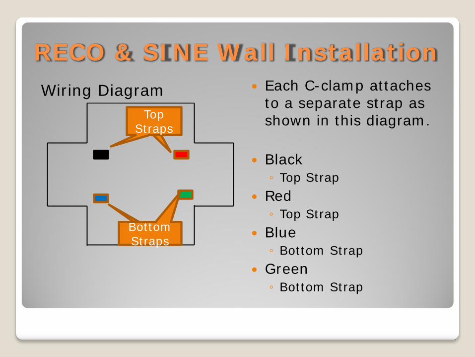
RECO & SINE Wall Installation Each C-clamp attaches
to a separate strap as shown in this diagram.
Black ◦ Top Strap
Red ◦ Top Strap
Blue ◦ Bottom Strap
Green ◦ Bottom Strap
Wiring Diagram Top
Straps
Bottom Straps
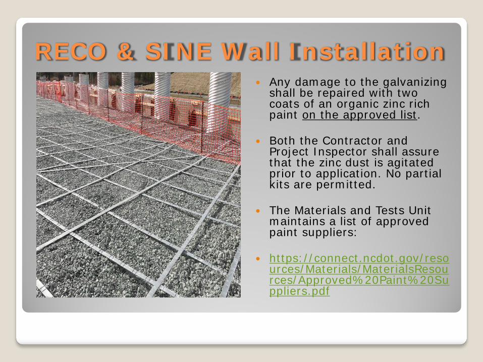
RECO & SINE Wall Installation Any damage to the galvanizing
shall be repaired with two coats of an organic zinc rich paint on the approved list.
Both the Contractor and
Project Inspector shall assure that the zinc dust is agitated prior to application. No partial kits are permitted.
The Materials and Tests Unit
maintains a list of approved paint suppliers:
https://connect.ncdot.gov/reso
urces/Materials/MaterialsResources/Approved%20Paint%20Suppliers.pdf
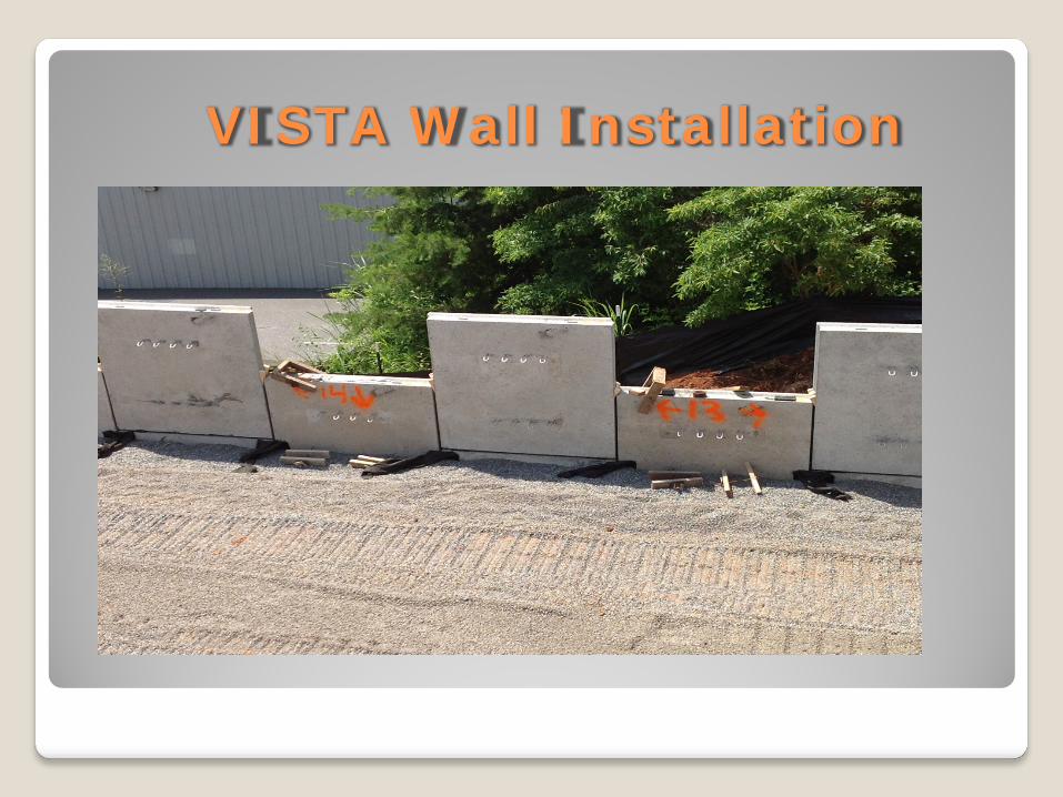
VISTA Wall Installation
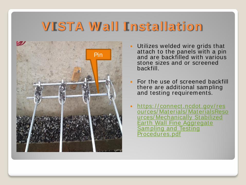
VISTA Wall Installation Utilizes welded wire grids that
attach to the panels with a pin and are backfilled with various stone sizes and or screened backfill.
For the use of screened backfill
there are additional sampling and testing requirements.
https://connect.ncdot.gov/res
ources/Materials/MaterialsResources/Mechanically Stabilized Earth Wall Fine Aggregate Sampling and Testing Procedures.pdf
Pin
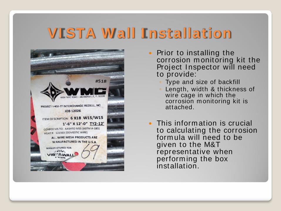
VISTA Wall Installation Prior to installing the
corrosion monitoring kit the Project Inspector will need to provide: ◦ Type and size of backfill ◦ Length, width & thickness of
wire cage in which the corrosion monitoring kit is attached.
This information is crucial
to calculating the corrosion formula will need to be given to the M&T representative when performing the box installation.
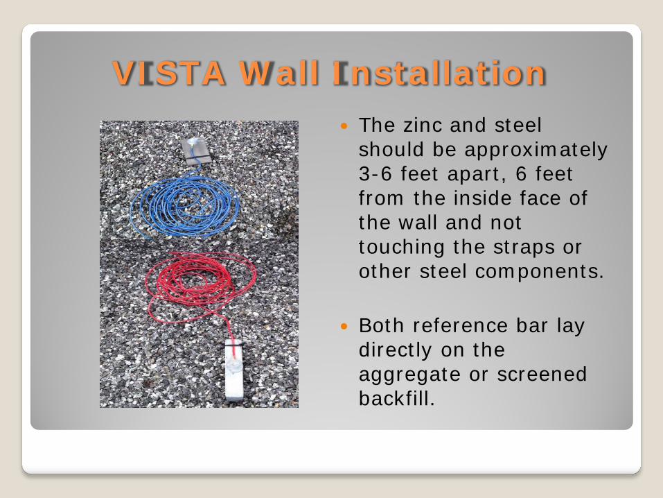
VISTA Wall Installation The zinc and steel
should be approximately 3-6 feet apart, 6 feet from the inside face of the wall and not touching the straps or other steel components.
Both reference bar lay
directly on the aggregate or screened backfill.
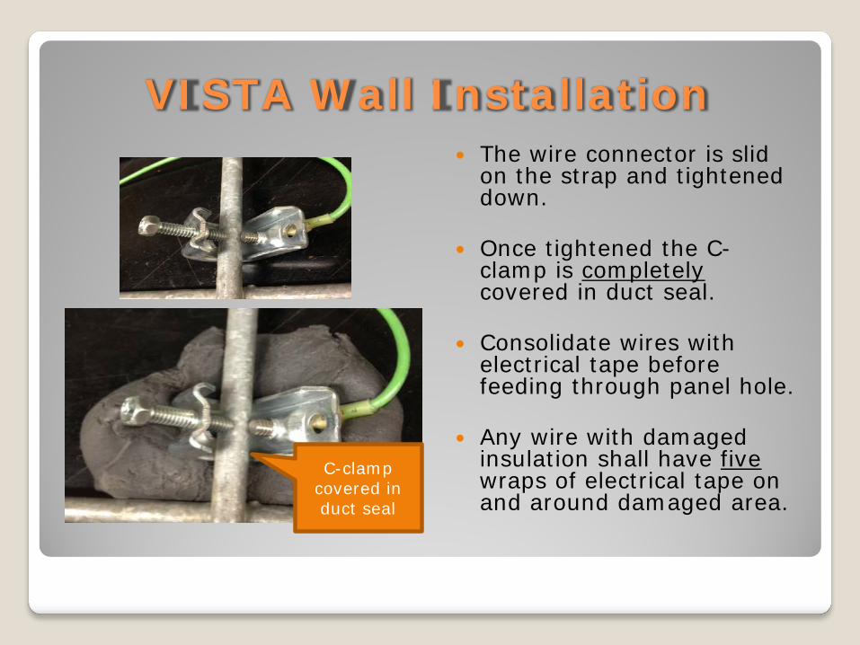
VISTA Wall Installation The wire connector is slid
on the strap and tightened down.
Once tightened the C-
clamp is completely covered in duct seal.
Consolidate wires with
electrical tape before feeding through panel hole.
Any wire with damaged
insulation shall have five wraps of electrical tape on and around damaged area.
C-clamp covered in duct seal
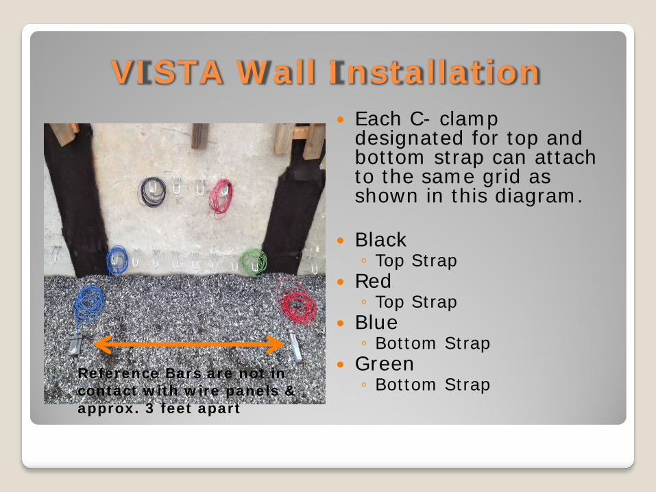
VISTA Wall Installation Each C- clamp
designated for top and bottom strap can attach to the same grid as shown in this diagram.
Black ◦ Top Strap
Red ◦ Top Strap
Blue ◦ Bottom Strap
Green ◦ Bottom Strap
Reference Bars are not in contact with wire panels & approx. 3 feet apart
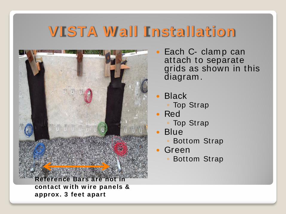
VISTA Wall Installation Each C- clamp can
attach to separate grids as shown in this diagram.
Black ◦ Top Strap
Red ◦ Top Strap
Blue ◦ Bottom Strap
Green ◦ Bottom Strap
Reference Bars are not in contact with wire panels & approx. 3 feet apart

VISTA Wall Installation Any damage to the galvanizing
shall be repaired with two coats of an organic zinc rich paint on the approved list.
Both the Contractor and Project
Inspector shall assure that the zinc dust is agitated prior to application. No partial kits are permitted.
The Materials and Tests Unit
maintains a list of approved paint suppliers:
https://connect.ncdot.gov/resou
rces/Materials/MaterialsResources/Approved%20Paint%20Suppliers.pdf

M&T Contact Information For MSE Wall Installation
State Field Operations Manager ◦ Todd Whittington, PE ◦ (919) 329-4220 ◦ [email protected]
Metals Engineer ◦ Randy Porter ◦ (919) 329-4202 ◦ [email protected]
Manufactured Products Engineer ◦ Cabell Garbee, II, PE ◦ (919) 329-4224 ◦ [email protected]
Coatings and Corrosion Engineer ◦ Aaron Dacey ◦ (919) 329-4102 Office ◦ [email protected]