Embed Size (px)
Citation preview
CASE STUDY:
USE OF MSE WALL STRUCTURES IN STAGED CONSTRUCTION ON COMPRESSIBLE SOILS, 156 STREET/YELLOWHEAD TRAIL INTERCHANGE, EDMONTON, AB. Paul J. Boos, Reinforced Earth Company Ltd., Edmonton, AB, Stuart Smith, BPTEC-DNW Engineering Ltd., Edmonton, AB, Renato Clementino, Thurber Engineering Ltd. Edmonton, AB, Bill Brockbank, Reinforced Earth Company Ltd., Mississauga, ON ABSTRACT This paper discusses the use of reinforced earth style MSE walls in the construction of the interchange carrying 156 street over Yellowhead Trail and the adjacent CNR right-of-way in Edmonton, AB. The MSE walls were used at the abutments of the structure spanning the CNR to shorten the span and along the shoulder of the west bound to northbound ramp reducing land requirements. The interchange construction was staged over three construction seasons with the design being continued concurrent with first stage of construction in 2004. The first stage of the construction included placing of wick drains (required to accelerate the dissipation of excess pore water pressures in the highly plastic clays) and the construction of the majority of the MSE wall structures. The MSE structures were built before placement of the H-Piles which were to support the bridge structure. This was accomplished by using casings in the MSE backfill during the wall construction. In particular we discuss the issues involved in the design and construction of the MSE wall as well as presenting the results of the construction generated pore pressure and settlement monitoring program carried out during construction. Le papier discutes l'utilization de mûre "MSE" au style de terre renforcer dans la construction de l'enterchange qui passe la 156 ieme rue audesus du "Yellowhead Trail" a la voie ferree du "CNR"au nord d'Edmonton, AB. Le mûre "MSE" utilizer au aboutement de la structure qui traversait la voie ferree "CNR" pour racoursir l'etenue et reduir le terrain requit pour le bord de la rampe est au nord. La construction de l"entrechange etait consus pour trois saisons consecutive, avac la premiere etage de construction en 2004. La premiere etage enclue le placement de des meches d'equout requibs pour l'acce'leration de la dissipation de l'eau excessive de l'argille plastique, et la construction de la majorities des mûre "MSE". Le mûre "MSE" etait batis avant de place les pilie "H" qui etait a supporte la construction du pont. Ceci etait accompli par l'utilization de casement dans le remplisage pendants la construction des mûres "MSE". Nous discuteront les issues parvennant du projet et de la construction des mûres "MSE" ainsis nous presenteront les resultats de les pression des espace genere par le construction ausis le programs de vaillage de stabilization pendant la construction. 1. INTRODUCTION The City of Edmonton is currently in the final stage of constructing a simple diamond interchange on the Yellowhead Trail at 156 Street. The project consisted of raising 156 Street to pass over the Yellowhead Trail on a revised alignment slightly west of the original intersection. As part of this interchange work, the at-grade crossing of 156 Street over the CN mainline immediately to the north of Yellowhead Trail is being replaced with an overpass structure carrying 156 street over the rail line. Mechanically Stabilized Earth (MSE) Retaining walls were included in the project as part of the bridge abutments for the overpass structure carrying the new 156 Street over the CNR mainline. The use of MSE walls was included to reduce the amount of land acquisition required for the
project. A complicating factor was that the soils in the area were found to be compressible and required the use of wick drains to control pore pressure dissipation during the construction. 2. PROJECT PLANNING In September of 2000, City Council approved the Concept Planning Study for the grade separation and railway overpass at 156 Street and Yellowhead Trail. The plan involved replacing the existing signalized intersection with the construction of an interchange structure that included bridge structures carrying 156 street over Yellowhead Trail and the CN railway tracks. The substantial completion of the construction was originally scheduled for 2007.
Sea to Sky Geotechnique 2006
184
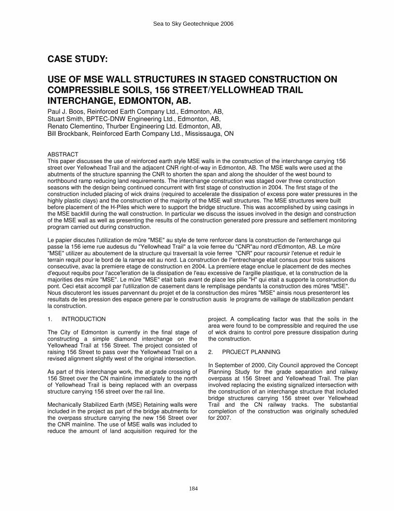
Figure 1 - Plan of 156 Street Interchange
The new 156 Street and Yellowhead Trail Interchange and CN Overpass were located in a light industrial/commercial area in northwest Edmonton as shown in Figure 1. The terrain was relatively flat, rising slightly towards the north. CN’s mainline tracks were located approximately 200m north of Yellowhead Trail with an at-grade crossing of the CN tracks by 156 Street. There were over 50 train movements per day affecting the crossing. The CN’s Bissell Yards were located immediately west of 156 Street so that at times when trains were being resorted at the yard traffic disruptions had the potential to be significant. Delays at the rail crossing had been a significant concern to companies in the area to the north of this crossing with indications that delays at the rail crossing cost some operators hundreds of thousands of dollars per year. During the preliminary design of the interchange, several amendments were made. In particular, an accelerated construction schedule, with construction starting in 2004 and completion of the interchange in 2006, and the addition of a loop ramp for traffic exiting 156 Street for westbound travel along Yellowhead Trail.
It was anticipated that the accelerated construction of the interchange will result in cost savings of nearly $3 million through engineered efficiencies and reduced inflation. The 2006 completion will also relieve traffic congestion and delays and facilitate earlier development of adjoining industrial lands. 2.1 Scheduling & Staging of Project In order to accommodate traffic throughout the construction period and to allow time for consolidation of the roadway and abutment fills, the project was broken up into stages. The project stages (as described on the City of Edmonton web page) were as follows: Stage 1: 2004 Construction • Place fill material for mainline roadwork on 156
Street north of Yellowhead Trail • Construct retaining walls beside CN railway tracks
and along 156 Street • Relocate Utilities • Rehabilitate/construct detour routes • Reconstruct 128 Avenue from 156 Street to 149
Street • Construct 149 Street from 131 Avenue to 137 Ave.
Sea to Sky Geotechnique 2006
185
Stages 2 & 3: 2005 Construction • Place fill material for mainline roadwork on 156
Street south of Yellowhead Trail • Construct connector roads surrounding the
interchange • Close 156 Street from 123A Avenue to 126 Avenue • Construct the Yellowhead Trail Ramps onto 156
Street • Construct the Storm Water Management Pond • Construct the CN/156 Street Bridge Stages 4 & 5: 2006 Construction • Construct 156 Street/Yellowhead Trail Bridge • Pave mainline road of 156 Street • Pave Yellowhead Trail Ramps onto 156 Street • Rehabilitate Yellowhead Trail from 149 Street to 162
Street • Open interchange - October 2006 The work discussed in this paper took part during stage 1 and the early part of stage 2 & 3 3. DESIGN OF RAIL STRUCTURE The design of the 156 street interchange structure was prepared for the City of Edmonton by BPTEC – DNW Engineering Ltd. In order to meet the accelerated schedule the design work was staged. The design for later stages of the project continued during the construction of the initial stages of the construction. The geometry of the bridge structure was determined by the geometry of the rail crossing. At the location of the crossing the structure spans multiple rail tracks. The number varies from four sets of tracks at the east edge of the structure up to six sets at the west edge due to the presence of two rail line switches within the bounds of the structure. This limited the bridge geometry to a single span structure as it was not possible to locate piers between the multiple rail lines. It also resulted in a unique flared geometry for the bridge structure. The unique flared shape of the bridge resulted in the choice of steel girders rather than pre-cast concrete girders. To match the flared geometry the length of the girders varied from the east to the west side of the bridge. Also due to the varying girder length, the girders were designed with three different depths, deeper girders for the longer lengths for the west side and shallower girders for the shorter lengths on the east side. This made each girder unique and pre-cast girders uneconomical. Full height MSE retaining walls were used at both abutments in order to minimize the bridge span. The bridge abutments were designed as integral abutments supported by H-Piles in order to eliminate expansion joints and to reduce future maintenance requirements. The selection of MSE retaining walls with pile foundations came from an evaluation of the soil conditions, which indicated that settlements and consolation of up to 200
mm would occur. Although a cast-in-place concrete retaining wall on piled foundations was feasible, the most cost effective solution was mechanically stabilized earth retaining walls. These walls have flexibility to accommodate settlements. Due to the predicted settlements it was not possible to construct the bridge foundation as being supported on the MSE fill. Pile supports were required. 3.1 Structural Design The bridge structures were designed in accordance with the Canadian Highway Bridge Code CSA S6 (2000). The design live load was the CL 800 truck. In addition the bridge structures were checked with their ability to support specialized overload trucks based on an analysis in accordance with Section 14 of CSA S6. As the proposed bridge crosses the CN tracks at the eastern end of Bissell Yards, it spans over turnouts on both the north and south sides of the mainline track. This resulted in the bridge ends(abutments) being non-parallel with the structural span varying from 35.3m at the east edge to 41.6m at the west edge. The bridge is a single span structure and carry six lanes of traffic plus a 3.0m wide sidewalk on the west side. In order to minimize the length of the bridge spans, full height MSE walls have been constructed parallel to the turnout tracks at both ends of the bridge. The walls need to be at least 7.925m offset from the outer tracks. 3.2 Geotechnical Evaluation & Design The geotechnical evaluation of the site was performed by Thurber Engineering Ltd. (2003) The geotechnical investigation consisting of 23 test holes was carried out in 2002 to assess the subsurface condition for the preliminary design of the interchange. Four supplementary test holes were drilled in 2003 to provide additional information for the detail design of the bridges, approach fills and the MSE walls. The results of the geotechnical investigation indicated that the ground condition consisted of a sequence of about 6 m of firm to very stiff compressible lacustrine clay, overlying very stiff to hard clay till, extending to approximately 30 m depth. Bedrock consisting of clay shale and very dense bentonitic sandstone layers was found below the clay till. The lacustrine clay had liquid limits ranging from 45% to 81% and plastic limit from 19% to 27%. Moisture contents varied form 22% to 48% but were typically about 35%, increasing slightly with depth. SPT N values varied from 5 to 19 with typical values of approximately 6 to 9. A multi-stage triaxial test was carried out on an undisturbed Shelby tube sample collected at 4.2m depth. The effective strength envelope indicated a friction angle of 21o with cohesion intercept of 10 kPa at the lower end and a friction angle of 26.5o with zero cohesion at the upper end of the stress range.
Sea to Sky Geotechnique 2006
186
Groundwater elevation measured in standpipe piezometers varied from 1.4 m to 5.3 m below existing ground surface. Stability analyses were carried out to assess the global stability of the proposed abutment fills retained by the MSE walls at the CNR overpass and side slope at 156 Street. The analyses included assessment of the end of construction condition based on effective stress analyses with construction generated excess pore water pressures, as well as long term stability after pore pressure dissipation. Pore pressures generated in the fill during placement and compaction have been estimated based on ru values in the range of 0.2 and 0.4, which covers a range of different fill materials from sandy medium plastic clay till to medium to high plastic clay. Strength parameter used for the foundation clay was in the range provided by the multi-stage triaxial. Minimum factor of safety of 1.3 and 1.5 were used for the end of construction and long-term stability condition, respectively. The following are the main results and conclusions of the stability analyses. A construction of a MSE wall was considered feasible for the CNR overpass and also along 156 Street east fill. However, the width of the MSE zone should be at least equal to 1.3 and 2.0 times the height of the wall, for the CNR overpass and 156 St. walls, respectively. Hence, the required minimum length of reinforcement to satisfy global stability was as follows: • CNR overpass – 13 m. • 156 Street – 11 m. The foundation clay was expected to generate relatively high construction pore pressures in response to fill placement. Therefore vertical wick drains were required beneath the MSE walls to allow dissipation of pore pressures. Furthermore the clay fill height behind the granular fill of the MSE wall needed to be limited to a height not greater than 8 m in the first season to satisfy short term stability. The remaining fill was placed in the following season after sufficient pore pressure dissipation. To monitor the construction generated pore pressure and fill performance geotechnical instrumentations were installed in the foundation clay behind the MSE walls. 3.3 MSE Wall Design 3.3.1 General As is common for projects involving MSE walls the design of the structures was included in the contract with the construction of the project and carried out after the tender (City of Edmonton, 2004) was let. When preparing tenders of this nature it is important that the information in the tender is clear on the extent of the
structures and eliminates uncertainty on the project requirements with respect to the overall stability of the location where the structures will be constructed. The presence of a thorough geotechnical review of the site, such as was provided for this project reduces the uncertainty in preparing tender quotations and will result in a lower cost to the project owner. In the case of this project the documents included wall elevation drawings that clearly showed the required top and bottom of the wall geometry allowing for the wall to be properly integrated into the overall project and the geotechnical parameters and requirements (discussed in section 3.2) of the project site. The provision of this information allows the MSE wall designer/supplier and the contractor carrying out the construction to provide the most economical solution possible during the brief tender period. If uncertainties exist at this point one can be assured that these will show up in the project costs as the worst case scenario will be assumed and bid and any later savings will accrue to the contractor not the owner. 3.3.2 Specifics Design of the MSE walls for this project was carried out by Reinforced Earth Company on behalf of the construction contractor. The walls for the 156 Street interchange were designed in accordance with CAN/CSA-S6-M00 (add year of publication) with the soil reinforcement rated for a 100 year lifespan given backfill that meets the requirements for pH, receptivity and chloride & sulphate content. The length of the soil reinforcement required was defined by the global stability analysis included in the geotechnical report. The wall design used standard pre-cast panels cruciform in shape with a thickness of 140mm and a nominal height and width of 1.5m. Panels of this size are convenient for construction as they are easily managed by a variety of moderate sized types of equipment common on most construction sites. Design calculations determined the frequency of the soil reinforcement required based on the characteristics of the backfill materials in the reinforced volume and behind and below the reinforced volume. The retaining wall design considered both the interim construction pre-loading during stage 1 of the construction and the size and shape of the completed embankment with traffic loading. A significant surcharge is applied to the wall by the backfill above the top of the MSE wall. This backfill slopes upward from the top of the retaining wall at a 3H:1V slope. The presence of the gravel blanket over top of the wick drain was not a large concern during the design stage as
Sea to Sky Geotechnique 2006
187
the drainage blanket is a granular material and could be integrated into the bottom of the reinforced volume. 4. CONSTRUCTION In order to expedite the construction of the interchange a contract was tendered and subsequently issued to Waiward Excavators Ltd. To perform the work designated as Stage 1 of the interchange construction. This contract was issued at the end of July 2004 and work at the site began in August. The scope of the work was limited to underground works, wick drain installation, earthworks and the supply and installation of MSE walls. Waiward excavators retained Rino Roadbuilding to perform the erection of the MSE walls. The contract specified that the work was limited to the work that could actually be accomplished during the 2004 construction season. A new contract was tendered in the spring of 2005 to cover subsequent stages of the project. Alberco Construction Ltd. was awarded the contract. Under Alberco’s contract Comcon Paving Stone was retained to complete the construction of the MSE walls. 4.1 MSE Wall Construction The construction of the MSE walls included in the project was divided between 2004 construction and the 2005 construction. The reasons for this were multiple. First it was desired to place the major portion of the backfill adjacent to the wall early in the construction process in order to allow the area to consolidate before the construction of the interchange structures. However, the portion of the MSE that curved away from the structure along the east to north bound ramp and the east end of the north abutment extended across the original alignment of 156 Street. These areas could not be constructed until the 156 Street roadway was closed for construction during the 2005 construction season. Finally the upper portions of the abutment walls – essentially the portion of the walls above the level of the pile cap could not be constructed until after the piles were installed and the pile cap/abutment had been constructed. The result of these considerations was that approximately ¾ of the MSE wall area could be constructed during the 2004 construction season and the remainder would be constructed in the 2005 season. In order to ensure consistency in the MSE product, the City of Edmonton determined that all of the design and material supply for the MSE walls would be included in the 2004 contract with Wayward Excavators. The material for the 2005 season was delivered to the project site in the fall of 2004 and stockpiled for use in 2005. Some portions of the wall could not be built to their final length until after the closure of 156 Street which was initiated in the summer of 2005. In order to allow the wall construction to proceed smoothly to its completion in these areas, the ends of the wall sections built in 2004
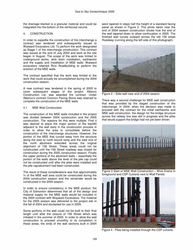
were tapered in steps half the height of a standard facing panel as shown in Figure 2. This photo taken near the end of 2004 season construction shows how the end of the wall tapered down to allow continuation in 2005. The finished wall curves outward across the old 156 street Roadway (running along the left side of this photograph)
Figure 2 – Side wall near end of 2004 season There was a second challenge for MSE wall construction that was provided by the staged construction of the interchange. In 2004, when the decision was made to proceed with the contract for the initial earthworks and MSE wall construction, the design for the bridge structure across the railway line was still in progress and the piles that would support the bridge had not yet been driven.
Figure 3 Start of MSE Wall Construction – Wick Drains in foreground and CSP Culverts next to Wall Panels
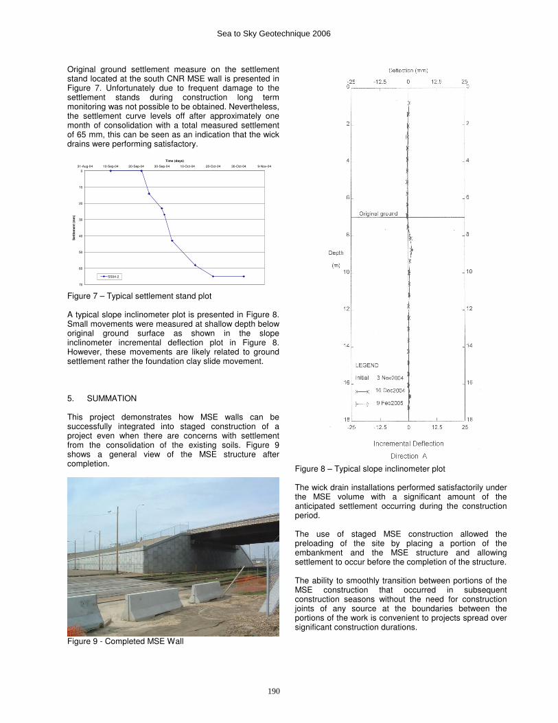
Figure 4 - Piles being installed through the CSP culverts.
Sea to Sky Geotechnique 2006
188
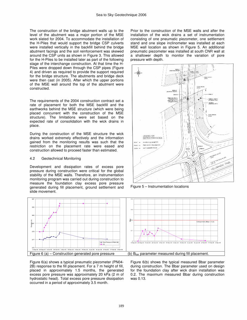
The construction of the bridge abutment walls up to the level of the abutment was a major portion of the MSE work slated for 2004. To accommodate the installation of the H-Piles that would support the bridge CSP culverts were installed vertically in the backfill behind the bridge abutment facings and the soil reinforcement was skewed around the CSP units as shown in Figure 3. This allowed for the H-Piles to be installed later as part of the following stage of the interchange construction. At that time the H-Piles were dropped down through the CSP pipes (Figure 4) and driven as required to provide the support required for the bridge structure. The abutments and bridge deck were then cast (in 2005). After which the upper portions of the MSE wall around the top of the abutment were constructed. The requirements of the 2004 construction contract set a rate of placement for both the MSE backfill and the earthworks behind the MSE structure (which were being placed concurrent with the construction of the MSE structure). The limitations were set based on the expected rate of consolidation with the wick drains in place. During the construction of the MSE structure the wick drains worked extremely effectively and the information gained from the monitoring results was such that the restriction on the placement rate were eased and construction allowed to proceed faster than estimated. 4.2 Geotechnical Monitoring Development and dissipation rates of excess pore pressure during construction were critical for the global stability of the MSE walls. Therefore, an instrumentation monitoring program was carried out during construction to measure the foundation clay excess pore pressure generated during fill placement, ground settlement and slide movement.
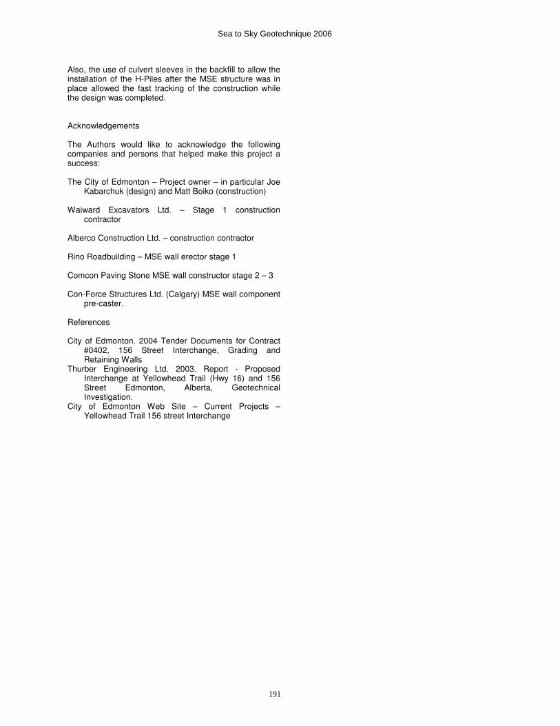
Prior to the construction of the MSE walls and after the installation of the wick drains a set of instrumentation consisting of one pneumatic piezometer, one settlement stand and one slope inclinometer was installed at each MSE wall location as shown in Figure 5. An additional pneumatic piezometer was installed at south CNR wall at a shallower depth to monitor the variation of pore pressure with depth.
Figure 5 – Instrumentation locations
675
677
679
681
683
685
687
5-Sep-04 20-Sep-04 5-Oct-04 20-Oct-04 4-Nov-04 19-Nov-04 4-Dec-04 19-Dec-04 3-Jan-05 18-Jan-05 2-Feb-05 17-Feb-05 4-Mar-05
Ele
vatio
n (m
)
Pore Pressure (PN04-2B)
Fill
0
0.1
0.2
0.3
0.4
5-Sep-04 20-Sep-04 5-Oct-04 20-Oct-04 4-Nov-04 19-Nov-04 4-Dec-04 19-Dec-04 3-Jan-05 18-Jan-05 2-Feb-05 17-Feb-05 4-Mar-05
Bbar
Critical limit (Bbar = 0.2)
Figure 6 (a) – Construction generated pore pressure (b) Bbar parameter measured during fill placement. Figure 6(a) shows a typical pneumatic piezometer (PN04-2B) response to the fill placement. For a 7 m height of fill, placed in approximately 1.5 months, the generated excess pore pressure was approximately 20 kPa (2 m of hydrostatic head). Total excess pore pressure dissipation occurred in a period of approximately 3.5 month.
Figure 6(b) shows the typical measured Bbar parameter during construction. The Bbar parameter used on design for the foundation clay after wick drain installation was 0.2. The maximum measured Bbar during construction was 0.13.
Sea to Sky Geotechnique 2006
189
Original ground settlement measure on the settlement stand located at the south CNR MSE wall is presented in Figure 7. Unfortunately due to frequent damage to the settlement stands during construction long term monitoring was not possible to be obtained. Nevertheless, the settlement curve levels off after approximately one month of consolidation with a total measured settlement of 65 mm, this can be seen as an indication that the wick drains were performing satisfactory.
A typical slope inclinometer plot is presented in Figure 8. Small movements were measured at shallow depth below original ground surface as shown in the slope inclinometer incremental deflection plot in Figure 8. However, these movements are likely related to ground settlement rather the foundation clay slide movement. 5. SUMMATION This project demonstrates how MSE walls can be successfully integrated into staged construction of a project even when there are concerns with settlement from the consolidation of the existing soils. Figure 9 shows a general view of the MSE structure after completion.
Figure 9 - Completed MSE Wall
Figure 8 – Typical slope inclinometer plot The wick drain installations performed satisfactorily under the MSE volume with a significant amount of the anticipated settlement occurring during the construction period. The use of staged MSE construction allowed the preloading of the site by placing a portion of the embankment and the MSE structure and allowing settlement to occur before the completion of the structure. The ability to smoothly transition between portions of the MSE construction that occurred in subsequent construction seasons without the need for construction joints of any source at the boundaries between the portions of the work is convenient to projects spread over significant construction durations.
0
10
20
30
40
50
60
70
31-Aug-04 10-Sep-04 20-Sep-04 30-Sep-04 10-Oct-04 20-Oct-04 30-Oct-04 9-Nov-04
Time (days)
Sett
lem
en
t (m
m)
SS04-2
Figure 7 – Typical settlement stand plot
Sea to Sky Geotechnique 2006
190
Also, the use of culvert sleeves in the backfill to allow the installation of the H-Piles after the MSE structure was in place allowed the fast tracking of the construction while the design was completed. Acknowledgements The Authors would like to acknowledge the following companies and persons that helped make this project a success: The City of Edmonton – Project owner – in particular Joe
Kabarchuk (design) and Matt Boiko (construction) Waiward Excavators Ltd. – Stage 1 construction
contractor Alberco Construction Ltd. – construction contractor Rino Roadbuilding – MSE wall erector stage 1 Comcon Paving Stone MSE wall constructor stage 2 – 3 Con-Force Structures Ltd. (Calgary) MSE wall component
pre-caster. References City of Edmonton. 2004 Tender Documents for Contract
#0402, 156 Street Interchange, Grading and Retaining Walls
Thurber Engineering Ltd. 2003. Report - Proposed Interchange at Yellowhead Trail (Hwy 16) and 156 Street Edmonton, Alberta, Geotechnical Investigation.
City of Edmonton Web Site – Current Projects – Yellowhead Trail 156 street Interchange
Sea to Sky Geotechnique 2006
191