Embed Size (px)
Citation preview
Software Product Name
Product Brochure
MS27103ARemote Spectrum Monitor
2
MS27103A Remote Spectrum Monitor
Introduction
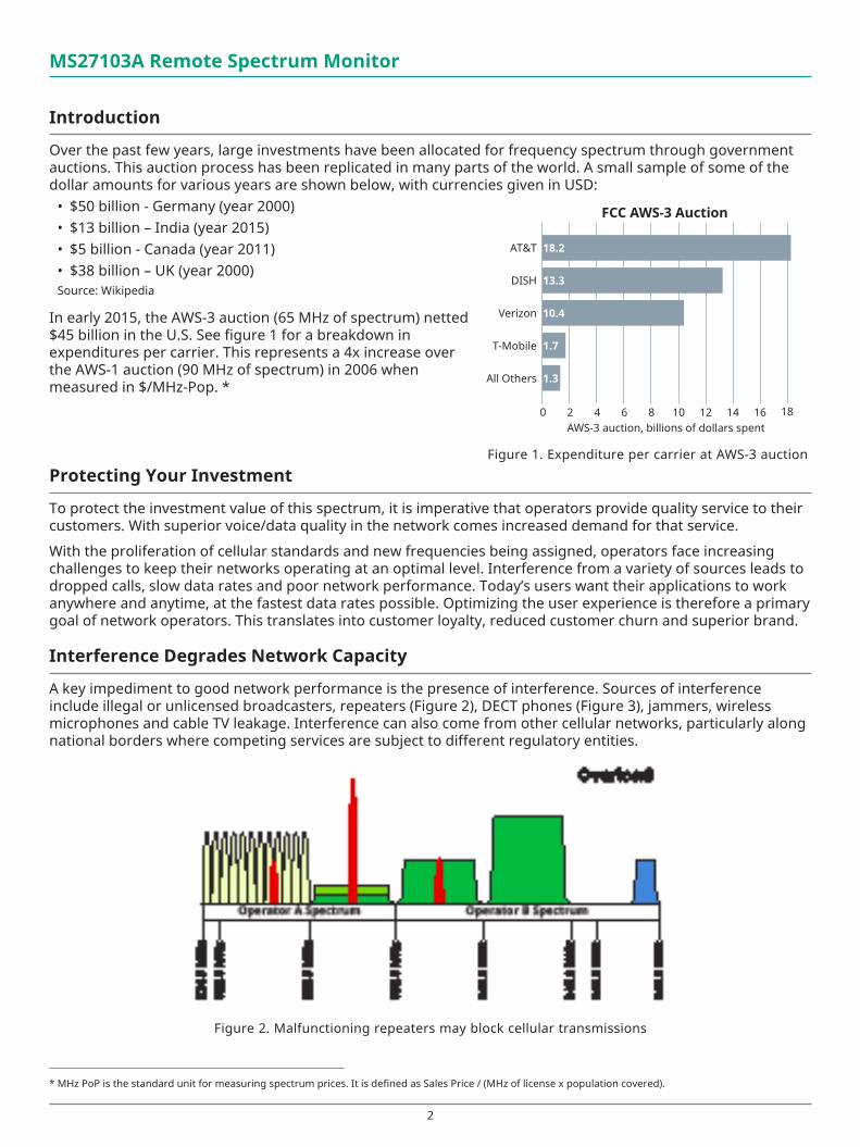
Over the past few years, large investments have been allocated for frequency spectrum through government auctions. This auction process has been replicated in many parts of the world. A small sample of some of the dollar amounts for various years are shown below, with currencies given in USD:
• $50 billion - Germany (year 2000)• $13 billion – India (year 2015)• $5 billion - Canada (year 2011)• $38 billion – UK (year 2000)Source: Wikipedia
In early 2015, the AWS-3 auction (65 MHz of spectrum) netted $45 billion in the U.S. See figure 1 for a breakdown in expenditures per carrier. This represents a 4x increase over the AWS-1 auction (90 MHz of spectrum) in 2006 when measured in $/MHz-Pop. *
Protecting Your Investment
To protect the investment value of this spectrum, it is imperative that operators provide quality service to their customers. With superior voice/data quality in the network comes increased demand for that service.
With the proliferation of cellular standards and new frequencies being assigned, operators face increasing challenges to keep their networks operating at an optimal level. Interference from a variety of sources leads to dropped calls, slow data rates and poor network performance. Today’s users want their applications to work anywhere and anytime, at the fastest data rates possible. Optimizing the user experience is therefore a primary goal of network operators. This translates into customer loyalty, reduced customer churn and superior brand.
Interference Degrades Network Capacity
A key impediment to good network performance is the presence of interference. Sources of interference include illegal or unlicensed broadcasters, repeaters (Figure 2), DECT phones (Figure 3), jammers, wireless microphones and cable TV leakage. Interference can also come from other cellular networks, particularly along national borders where competing services are subject to different regulatory entities.
Figure 2. Malfunctioning repeaters may block cellular transmissions
Figure 1. Expenditure per carrier at AWS-3 auction
* MHz PoP is the standard unit for measuring spectrum prices. It is defined as Sales Price / (MHz of license x population covered).
AT&T
DISH
Verizon
T-Mobile
All Others
18.2
13.3
10.4
1.7
1.3
FCC AWS-3 Auction
AWS-3 auction, billions of dollars spent0 2 4 6 8 10 12 14 16 18
3
MS27103A Remote Spectrum Monitor
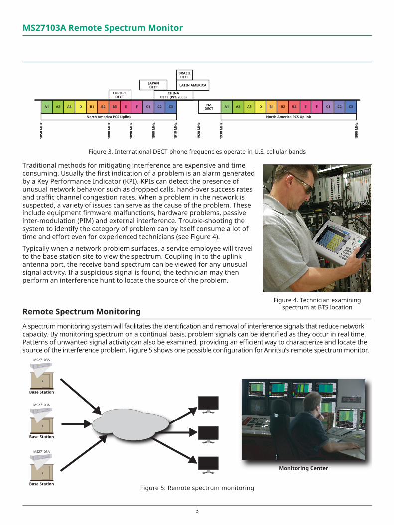
A1 A2 A3 D B1 B2 B3 E F C1 C2 C3 A1 A2 A3 D B1 B2 B3 E F C1 C2 C3
North America PCS Uplink North America PCS Uplink
EUROPEDECT
NADECT
BRAZILDECT
JAPANDECT
CHINADECT (Pre 2003)
LATIN AMERICA
1850
MH
z
1880
MH
z
1890
MH
z
1900
MH
z
1910
MH
z
1920
MH
z
1930
MH
z
1990
MH
z
Figure 3. International DECT phone frequencies operate in U.S. cellular bands
Traditional methods for mitigating interference are expensive and time consuming. Usually the first indication of a problem is an alarm generated by a Key Performance Indicator (KPI). KPIs can detect the presence of unusual network behavior such as dropped calls, hand-over success rates and traffic channel congestion rates. When a problem in the network is suspected, a variety of issues can serve as the cause of the problem. These include equipment firmware malfunctions, hardware problems, passive inter-modulation (PIM) and external interference. Trouble-shooting the system to identify the category of problem can by itself consume a lot of time and effort even for experienced technicians (see Figure 4).
Typically when a network problem surfaces, a service employee will travel to the base station site to view the spectrum. Coupling in to the uplink antenna port, the receive band spectrum can be viewed for any unusual signal activity. If a suspicious signal is found, the technician may then perform an interference hunt to locate the source of the problem.
Remote Spectrum Monitoring
A spectrum monitoring system will facilitates the identification and removal of interference signals that reduce network capacity. By monitoring spectrum on a continual basis, problem signals can be identified as they occur in real time. Patterns of unwanted signal activity can also be examined, providing an efficient way to characterize and locate the source of the interference problem. Figure 5 shows one possible configuration for Anritsu’s remote spectrum monitor.
Figure 4. Technician examining spectrum at BTS location
Monitoring Center
Base Station
MS27103A
Base Station
MS27103A
Base Station
MS27103A
Figure 5: Remote spectrum monitoring
4
MS27103A Remote Spectrum Monitor
MS27103A Remote Spectrum Monitor
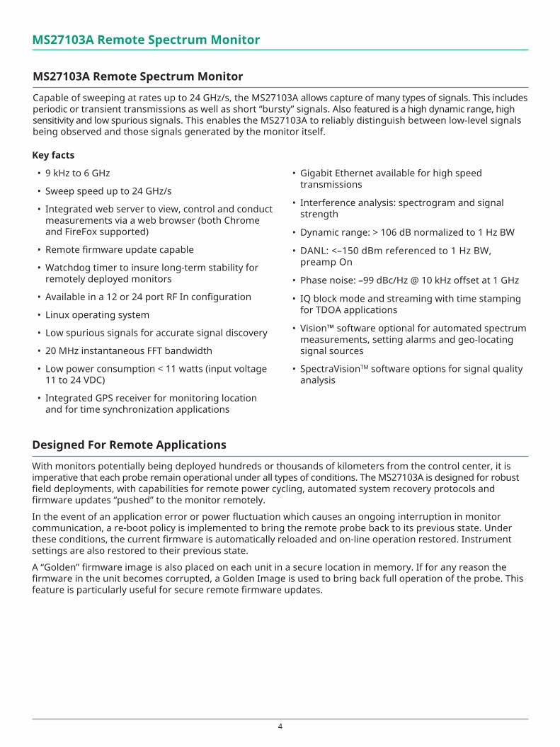
Capable of sweeping at rates up to 24 GHz/s, the MS27103A allows capture of many types of signals. This includes periodic or transient transmissions as well as short “bursty” signals. Also featured is a high dynamic range, high sensitivity and low spurious signals. This enables the MS27103A to reliably distinguish between low-level signals being observed and those signals generated by the monitor itself.
Key facts
• 9 kHz to 6 GHz
• Sweep speed up to 24 GHz/s
• Integrated web server to view, control and conduct measurements via a web browser (both Chrome and FireFox supported)
• Remote firmware update capable
• Watchdog timer to insure long-term stability for remotely deployed monitors
• Available in a 12 or 24 port RF In configuration
• Linux operating system
• Low spurious signals for accurate signal discovery
• 20 MHz instantaneous FFT bandwidth
• Low power consumption < 11 watts (input voltage 11 to 24 VDC)
• Integrated GPS receiver for monitoring location and for time synchronization applications
• Gigabit Ethernet available for high speed transmissions
• Interference analysis: spectrogram and signal strength
• Dynamic range: > 106 dB normalized to 1 Hz BW
• DANL: <–150 dBm referenced to 1 Hz BW, preamp On
• Phase noise: –99 dBc/Hz @ 10 kHz offset at 1 GHz
• IQ block mode and streaming with time stamping for TDOA applications
• Vision™ software optional for automated spectrum measurements, setting alarms and geo-locating signal sources
• SpectraVisionTM software options for signal quality analysis
Designed For Remote Applications
With monitors potentially being deployed hundreds or thousands of kilometers from the control center, it is imperative that each probe remain operational under all types of conditions. The MS27103A is designed for robust field deployments, with capabilities for remote power cycling, automated system recovery protocols and firmware updates “pushed” to the monitor remotely.
In the event of an application error or power fluctuation which causes an ongoing interruption in monitor communication, a re-boot policy is implemented to bring the remote probe back to its previous state. Under these conditions, the current firmware is automatically reloaded and on-line operation restored. Instrument settings are also restored to their previous state.
A “Golden” firmware image is also placed on each unit in a secure location in memory. If for any reason the firmware in the unit becomes corrupted, a Golden Image is used to bring back full operation of the probe. This feature is particularly useful for secure remote firmware updates.
5
MS27103A Remote Spectrum Monitor
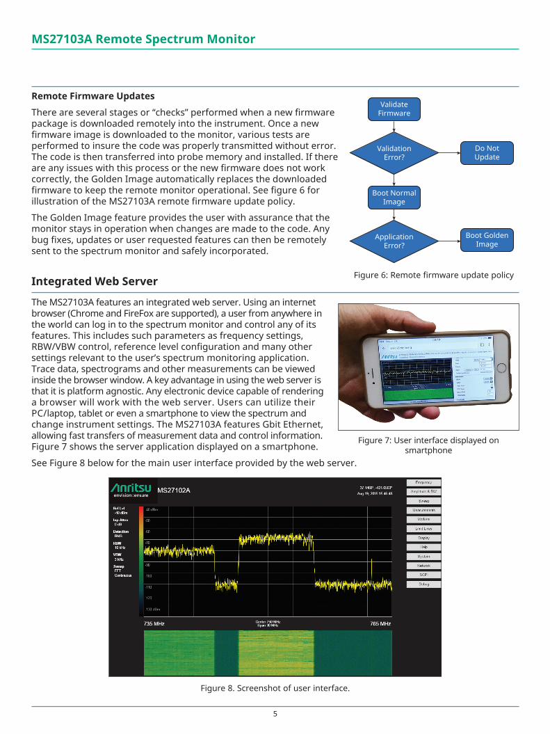
Remote Firmware Updates
There are several stages or “checks” performed when a new firmware package is downloaded remotely into the instrument. Once a new firmware image is downloaded to the monitor, various tests are performed to insure the code was properly transmitted without error. The code is then transferred into probe memory and installed. If there are any issues with this process or the new firmware does not work correctly, the Golden Image automatically replaces the downloaded firmware to keep the remote monitor operational. See figure 6 for illustration of the MS27103A remote firmware update policy.
The Golden Image feature provides the user with assurance that the monitor stays in operation when changes are made to the code. Any bug fixes, updates or user requested features can then be remotely sent to the spectrum monitor and safely incorporated.
Integrated Web Server
The MS27103A features an integrated web server. Using an internet browser (Chrome and FireFox are supported), a user from anywhere in the world can log in to the spectrum monitor and control any of its features. This includes such parameters as frequency settings, RBW/VBW control, reference level configuration and many other settings relevant to the user’s spectrum monitoring application. Trace data, spectrograms and other measurements can be viewed inside the browser window. A key advantage in using the web server is that it is platform agnostic. Any electronic device capable of rendering a browser will work with the web server. Users can utilize their PC/laptop, tablet or even a smartphone to view the spectrum and change instrument settings. The MS27103A features Gbit Ethernet, allowing fast transfers of measurement data and control information. Figure 7 shows the server application displayed on a smartphone.
See Figure 8 below for the main user interface provided by the web server.
Figure 8. Screenshot of user interface.
ValidateFirmware
ValidationError?
Boot NormalImage
ApplicationError?
Do NotUpdate
Boot GoldenImage
Figure 6: Remote firmware update policy
Figure 7: User interface displayed on smartphone
6
MS27103A Remote Spectrum Monitor
Hardware
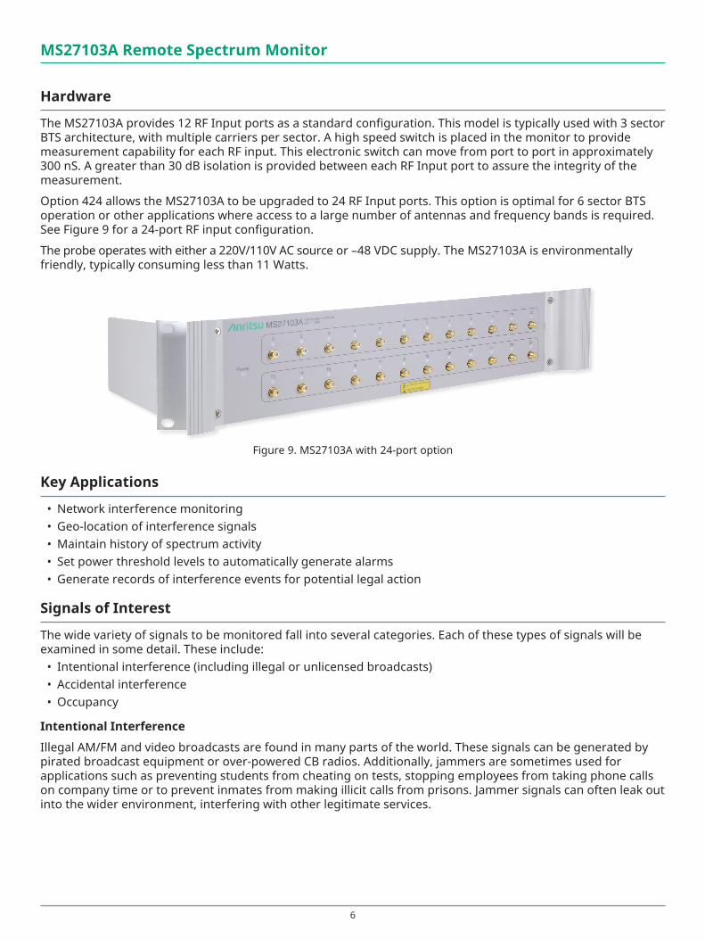
The MS27103A provides 12 RF Input ports as a standard configuration. This model is typically used with 3 sector BTS architecture, with multiple carriers per sector. A high speed switch is placed in the monitor to provide measurement capability for each RF input. This electronic switch can move from port to port in approximately 300 nS. A greater than 30 dB isolation is provided between each RF Input port to assure the integrity of the measurement.
Option 424 allows the MS27103A to be upgraded to 24 RF Input ports. This option is optimal for 6 sector BTS operation or other applications where access to a large number of antennas and frequency bands is required. See Figure 9 for a 24-port RF input configuration.
The probe operates with either a 220V/110V AC source or –48 VDC supply. The MS27103A is environmentally friendly, typically consuming less than 11 Watts.
Key Applications
• Network interference monitoring• Geo-location of interference signals• Maintain history of spectrum activity • Set power threshold levels to automatically generate alarms• Generate records of interference events for potential legal action
Signals of Interest
The wide variety of signals to be monitored fall into several categories. Each of these types of signals will be examined in some detail. These include:
• Intentional interference (including illegal or unlicensed broadcasts)• Accidental interference• Occupancy
Intentional Interference
Illegal AM/FM and video broadcasts are found in many parts of the world. These signals can be generated by pirated broadcast equipment or over-powered CB radios. Additionally, jammers are sometimes used for applications such as preventing students from cheating on tests, stopping employees from taking phone calls on company time or to prevent inmates from making illicit calls from prisons. Jammer signals can often leak out into the wider environment, interfering with other legitimate services.
Figure 9. MS27103A with 24-port option
7
MS27103A Remote Spectrum Monitor
Accidental Interference
A wide variety of accidental interference can be seen in the spectrum. A common problem is cable TV leakage. This type of leakage exists both from cable signals leaking into the outside environment as well as from outside signals leaking into the cable system. This problem has been enhanced with the transmission of cable signals into frequency bands used by broadcasters and cellula operations (such as the 700 MHz LTE band).
DECT phones also cause interference problems, particularly when people bring their wireless phones along when moving from one country to another. DECT frequencies vary in different countries, providing the potential for interference when transported.
Other sources of interference include cellular signals (due to antenna tilt or azimuth errors), repeaters oscillating, wireless microphone problems, power equipment and many others.
Occupancy
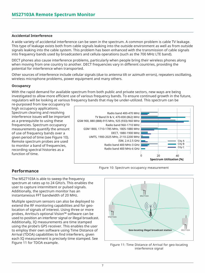
With the rapid demand for available spectrum from both public and private sectors, new ways are being investigated to allow more efficient use of various frequency bands. To ensure continued growth in the future, regulators will be looking at various frequency bands that may be under-utilized. This spectrum can be re-purposed from low occupancy to high occupancy applications. Spectrum clearing and resolving interference issues will be important as a prerequisite to using these frequencies. Spectrum occupancy measurements quantify the amount of use of frequency bands over a given period of time (see Figure 10). Remote spectrum probes are used to monitor a band of frequencies, recording spectral histories as a function of time.
Performance
The MS27103A is able to sweep the frequency spectrum at rates up to 24 GHz/s. This enables the user to capture intermittent or pulsed signals. Additionally, the spectrum monitor has an instantaneous FFT bandwidth of 20 MHz.
Multiple spectrum sensors can also be deployed to extend the RF monitoring capabilities and for geo-location of signals of interest. Using three or more probes, Anritsu’s optional Vision™ software can be used to position an interferer signal or illegal broadcast. Additionally, IQ measurements are time stamped using the probe’s GPS receiver. This enables the user to employ their own software using Time Distance of Arrival (TDOA) capabilities to find interferers, given each IQ measurement is precisely time stamped. See Figure 11 for TDOA example.
MS27102A
MS27102A
MS27102A
MS27102A
MS27102A
MS27102AGeo-locating illegal broadcast station
Figure 11: Time Distance of Arrival for geo-locating interference signal
Radio band 400-470 MHz TV Band IV & V, 470-830 (862) MHz
GSM 900, 880 (888)-915 MHz, 925 (933)-960 MHz Radio band 960-1710 MHz
GSM 1800, 1710-1785 MHz, 1805-1880 MHz DECT, 1880-1900 MHz
UMTS, 1900-2025 MHz, 2110-2200 MHz ISM, 2.4-2.5 GHz
Radio band 400 MHz-3 GHz Radio band 400 MHz-6 GHz
0 20 40 Spectrum Utilization [%]
City A City B City C
Figure 10: Spectrum occupancy measurement
8
Communications
Communications with the MS27103A are conducted either via wired Ethernet or wireless modem. Each monitor is shipped with a pre-programmed static IP address. After making a connection with this IP address, users can then change the address to a difference static IP. Alternatively, DHCP or DNS may be used. See Anritsu’s Ethernet Configuration Guide for details.
All commands and inquiries with the MS27103A are done using SCPI commands. Anritsu provides a user manual listing each SCPI command, a description of each command and the correct syntax for each command. Users may develop their own list of SCPI commands and save to a text (.txt) file. This file can then be downloaded to the spectrum monitor for execution.
Summary
Key benefits for Anritsu remote spectrum monitoring include both automation and scalability. To minimize expenses while preserving network integrity, a highly automated process is needed. The MS27103A takes a lot of the guesswork out of identifying causes for slow data rates or dropped calls. Using Anritsu’s Vision software or your own applications, users can identify patterns of interference, record spectrum history and geo-locate the sources of problem signals. The MS27103A is also highly scalable. Additional monitors can be added to your network seamlessly as the need for interference mitigation grows. Also, new features and options that become available can be added remotely. No site visits required. Together with other Anritsu interference and PIM mitigation products, Anritsu provides the total solution to insure the integrity of your valuable spectrum.
MS27103A Remote Spectrum Monitor
® Anritsu All trademarks are registered trademarks of their respective owners. Data subject to change without notice. For the most recent specifications visit: www.anritsu.com
11410-00874, Rev. D Printed in United States 2018-01©2018 Anritsu Company. All Rights Reserved.
Anritsu utilizes recycled paper and environmentally conscious inks and toner.
• United States Anritsu Company1155 East Collins Boulevard, Suite 100, Richardson, TX, 75081 U.S.A. Toll Free: 1-800-267-4878 Phone: +1-972-644-1777 Fax: +1-972-671-1877
• Canada Anritsu Electronics Ltd.700 Silver Seven Road, Suite 120, Kanata, Ontario K2V 1C3, Canada Phone: +1-613-591-2003 Fax: +1-613-591-1006
• Brazil Anritsu Electrônica Ltda.Praça Amadeu Amaral, 27 - 1 Andar 01327-010 - Bela Vista - Sao Paulo - SP - Brazil Phone: +55-11-3283-2511 Fax: +55-11-3288-6940
• Mexico Anritsu Company, S.A. de C.V.Av. Ejército Nacional No. 579 Piso 9, Col. Granada 11520 México, D.F., México Phone: +52-55-1101-2370 Fax: +52-55-5254-3147
• United Kingdom Anritsu EMEA Ltd.200 Capability Green, Luton, Bedfordshire LU1 3LU, U.K. Phone: +44-1582-433280 Fax: +44-1582-731303
• France Anritsu S.A.12 avenue du Québec, Batiment Iris 1-Silic 612, 91140 Villebon-sur-Yvette, France Phone: +33-1-60-92-15-50 Fax: +33-1-64-46-10-65
• Germany Anritsu GmbHNemetschek Haus, Konrad-Zuse-Platz 1 81829 München, Germany Phone: +49-89-442308-0 Fax: +49-89-442308-55
• Italy Anritsu S.r.l.Via Elio Vittorini 129, 00144 Roma Italy Phone: +39-06-509-9711 Fax: +39-06-502-2425
• Sweden Anritsu ABKistagången 20B, 164 40 KISTA, Sweden Phone: +46-8-534-707-00 Fax: +46-8-534-707-30
• Finland Anritsu ABTeknobulevardi 3-5, FI-01530 VANTAA, Finland Phone: +358-20-741-8100 Fax: +358-20-741-8111
• Denmark Anritsu A/SKay Fiskers Plads 9, 2300 Copenhagen S, Denmark Phone: +45-7211-2200 Fax: +45-7211-2210
• Russia Anritsu EMEA Ltd. Representation Office in RussiaTverskaya str. 16/2, bld. 1, 7th floor. Moscow, 125009, Russia Phone: +7-495-363-1694 Fax: +7-495-935-8962
• Spain Anritsu EMEA Ltd. Representation Office in SpainEdificio Cuzco IV, Po. de la Castellana, 141, Pta. 5 28046, Madrid, Spain Phone: +34-915-726-761 Fax: +34-915-726-621
• United Arab Emirates Anritsu EMEA Ltd. Dubai Liaison OfficeP O Box 500413 - Dubai Internet City Al Thuraya Building, Tower 1, Suite 701, 7th floor Dubai, United Arab Emirates Phone: +971-4-3670352 Fax: +971-4-3688460
• India Anritsu India Pvt Ltd.2nd & 3rd Floor, #837/1, Binnamangla 1st Stage, Indiranagar, 100ft Road, Bangalore - 560038, India Phone: +91-80-4058-1300 Fax: +91-80-4058-1301
• Singapore Anritsu Pte. Ltd.11 Chang Charn Road, #04-01, Shriro House Singapore 159640 Phone: +65-6282-2400 Fax: +65-6282-2533
• P. R. China (Shanghai) Anritsu (China) Co., Ltd.27th Floor, Tower A, New Caohejing International Business Center No. 391 Gui Ping Road Shanghai, Xu Hui Di District, Shanghai 200233, P.R. China Phone: +86-21-6237-0898 Fax: +86-21-6237-0899
• P. R. China (Hong Kong) Anritsu Company Ltd.Unit 1006-7, 10/F., Greenfield Tower, Concordia Plaza, No. 1 Science Museum Road, Tsim Sha Tsui East, Kowloon, Hong Kong, P. R. China Phone: +852-2301-4980 Fax: +852-2301-3545
• Japan Anritsu Corporation8-5, Tamura-cho, Atsugi-shi, Kanagawa, 243-0016 Japan Phone: +81-46-296-6509 Fax: +81-46-225-8359
• Korea Anritsu Corporation, Ltd.5FL, 235 Pangyoyeok-ro, Bundang-gu, Seongnam-si, Gyeonggi-do, 13494 Korea Phone: +82-31-696-7750 Fax: +82-31-696-7751
• Australia Anritsu Pty Ltd.Unit 20, 21-35 Ricketts Road, Mount Waverley, Victoria 3149, Australia Phone: +61-3-9558-8177 Fax: +61-3-9558-8255
• Taiwan Anritsu Company Inc.7F, No. 316, Sec. 1, Neihu Rd., Taipei 114, Taiwan Phone: +886-2-8751-1816 Fax: +886-2-8751-1817
Specifications are subject to change without notice.