Embed Size (px)
Citation preview

0
FORM-1
FOR
PROPOSED PESTICIDE INTERMEDIATES AND
SPECIALTY CHEMICALS IN EXISTING UNIT
OF
M/s. ACETO CHEM PVT. LTD. (UNIT-II)
PLOT NO. 274/3/1, GIDC ESTATE, PANDESARA,
DIST: SURAT – 394 221, GUJARAT
NABL Accredited Testing Laboratory
ISO 9001:2008 Certified Company
Aqua-Air Environmental Engineers P. Ltd.
403, Centre Point, Nr. Kadiwala School, Ring
Road, Surat - 395002
Prepared By:
NABL Accredited Testing Laboratory
ISO 9001:2008 Certified Company
Aqua-Air Environmental Engineers P. Ltd.
403, Centre Point, Nr. Kadiwala School, Ring
Road, Surat - 395002
NABL Accredited Testing Laboratory
ISO 9001:2008 Certified Company
Aqua-Air Environmental Engineers P. Ltd.
403, Centre Point, Nr. Kadiwala School, Ring
Road, Surat - 395002
Prepared By:

1
APPENDIX I
(See paragraph - 6)
FORM 1
(I) Basic Information
Sr.
No.
Item Details
1. Name of the project/s Aceto Chem Pvt. Ltd. (Unit-II)
2. S. No. in the schedule 5(b) & 5(f)
3. Proposed capacity/area/length/tonnage to be
handled/command area/lease area/number of
wells to be drilled
For detail Please refer Annexure – I
4. New/Expansion/Modernization Expansion
5. Existing Capacity/Area etc. --
6. Category of Project i.e. ‘A’ or ‘B’ ‘A’
7. Does it attract the general condition? If yes,
please specify.
No
8. Does it attract the specific condition? If yes,
please specify.
No
9. Location
Plot/Survey/Khasra No. Plot No. 274/3/1
Village GIDC Estate, Pandesara,
Tehsil Choryasi
District Surat
State Gujarat
10. Nearest railway station/airport along with
distance in kms.
Surat: 10 Km
11. Nearest Town, city, District Headquarters along
with distance in kms.
Surat: 10 Km
12. Village Panchayats, Zilla Parishad, Municipal
Corporation, local body (complete postal
address with telephone nos. to be given)
Not applicable
13. Name of the applicant Aceto Chem Pvt. Ltd. (Unit-II)
14. Registered Address M/s. Aceto Chem Pvt. Ltd. (Unit-II)
Plot No. 274/3/1, GIDC Estate, Pandesara, Dist:
Surat, Gujarat – 394 221
15. Address for correspondence: M/s. Aceto Chem Pvt. Ltd. (Unit-II)
Plot No. 274/3/1, GIDC Estate, Pandesara, Dist:
Surat, Gujarat – 394 221
Name Mr. Bansibhai D. Patel
Designation (Owner/Partner/CEO) Director
Address M/s. Aceto Chem Pvt. Ltd. (Unit-II)
Plot No. 274/3/1, GIDC Estate, Pandesara, Dist:
Surat, Gujarat – 394 221
Pin Code 394 221
E-mail [email protected]
Telephone No. 0261 –2890998/88
Fax No. 0261 – 2892345

2
16. Details of Alternative Sites examined, if any.
Location of these sites should be shown on a
topo sheet.
NA
17. Interlinked Projects No
18. Whether separate application of interlinked
project has been submitted?
No
19. If yes, date of submission No
20. If no, reason No
21. Whether the proposal involves
approval/clearance under: if yes, details of the
same and their status to be given.
(a) The Forest (Conservation) Act, 1980?
(b) The Wildlife (Protection) Act, 1972?
(c) The C.R.Z. Notification, 1991?
No
22. Whether there is any Government Order/Policy
relevant/relating to the site?
No
23. Forest land involved (hectares) No
24. Whether there is any litigation pending against
the project and/or land in which the project is
propose to be set up?
(a) Name of the Court
(b) Case No.
(c) Orders/directions of the Court, if any and its
relevance with the proposed project.
No
Capacity corresponding to sectoral activity (such as production capacity for manufacturing, mining
lease area and production capacity for mineral production, area for mineral exploration, length for
linear transport infrastructure, generation capacity for power generation etc.

3
(II) Activity
1. Construction, operation or decommissioning of the Project involving actions, which will cause
physical changes in the locality (topography, land use, changes in water bodies, etc.)
Sr.
No.
Information/Checklist confirmation Yes/
No
Details thereof with approximate quantities
frates, wherever possible) with source of
information data
1.1 Permanent or temporary change in land
use, land cover or topography including
increase intensity of land use (with respect
to local land use plan)
No Proposed expansion is within existing unit in
Pandesara GIDC Industrial Estate
1.2 Clearance of existing land, vegetation and
Buildings?
Yes Minor site clearance activities shall be carried
out to clear shrubs and weed.
1.3 Creation of new land uses?
No The project site is located on level ground,
which does not require any major land filling
for area grading work.
1.4 Pre-construction investigations e.g. bore
Houses, soil testing?
No
1.5 Construction works?
Yes For detail Please refer Annexure – II
1.6 Demolition works? No There will not be any demolition work at the
site.
1.7 Temporary sites used for construction
works or housing of construction workers?
No
1.8 Above ground buildings, structures or
earthworks including linear structures, cut
and fill or excavations
No
1.9 Underground works mining or tunneling?
No
1.10 Reclamation works?
No
1.11 Dredging?
No
1.12 Off shore structures?
No
1.13 Production and manufacturing processes?
Yes For detail Please refer Annexure -III
1.14 Facilities for storage of goods or materials?
Yes Areas for storage of raw materials and
finished products will be developed for the
proposed expansion project.
1.15 Facilities for treatment or disposal of solid
waste or liquid effluents?
Yes Details of the Liquid Effluent are given as
Annexure – V and details of solid waste are
given as Annexure –VI.
1.16 Facilities for long term housing of
operational workers?
No
1.17 New road, rail or sea traffic during No
4
Construction or Operation?
1.18 New road, rail, air waterborne or other
transport infrastructure including new or
altered routes and stations, ports, airports
etc?
No
1.19 Closure or diversion of existing transport
routes or infrastructure leading to changes
in traffic movements?
No
1.20 New or diverted transmission lines or
Pipelines?
No
1.21 Impoundment, damming, culverting,
realignment or other changes to the
hydrology of watercourses or aquifers?
No
1.22 Stream crossings?
No
1.23 Abstraction or transfers of water form
ground or surface waters?
Yes Water requirement is met through Surat
Municipal Corporation (SMC).
1.24 Changes in water bodies or the land
surface
Affecting drainage or run-off?
No
1.25 Transport of personnel or materials for
construction, operation or
decommissioning?
Yes By road only.
1.26 Long-term dismantling or decommissioning
or restoration works?
No
1.27 Ongoing activity during decommissioning
which could have an impact on the
environment?
No
1.28 Influx of people to an area either
temporarily or permanently?
No
1.29 Introduction of alien species?
No
1.30 Loss of native species or genetic diversity?
No
1.31 Any other actions? No

5
2. Use of Natural resources for construction or operation of the Project (such as land, water,
materials or energy, especially any resources which are non-renewable or in short supply):
Sr.
No.
Information/checklist confirmation Yes/No Details there of (with approximate quantities
frates, wherever possible) with source of
information data
2.1 Land especially undeveloped or agricultural
land (ha)
No
2.2 Water (expected source & competing users)
unit: KLD
Yes Water requirement is met through the SMC.
Water balance is given as Annexure – IV.
2.3 Minerals (MT) No
2.4 Construction material - stone, aggregates,
and / soil (expected source - MT)
Yes Construction materials like steel, cement,
crushed stones, sand, rubble, etc. required for
the project shall be procured from the local
market of the region.
2.5 Forests and timber (source - MT) No.
2.6 Energy including electricity and fuels (source,
competing users) Unit: fuel (MT), energy
(MW)
Yes Fuel
Natural Gas: 82 SCM/day (Existing)
Diesel: 30 Lit/Hr (Existing)
Natural Gas: 82 SCM/day (Total Proposed)
Diesel: 75 Lit/Hr (Total Proposed)
Energy :
90 HP from DGVCL.
2.7 Any other natural resources (use appropriate
standard units)
No
3. Use, storage, transport, handling or production of substances or materials, which could be
harmful to human health or the environment or raise concerns about actual or perceived
risks to human health.
Sr.
No.
Information/Checklist confirmation Yes/No Details there of (with approximate
quantities/rates, wherever possible) with
source of information data
3.1 Use of substances or materials, which are
hazardous (as per MSIHC rules) to human
health or the environment (flora, fauna, and
water supplies)
Yes For detail please refer Annexure – VIII
3.2 Changes in occurrence of disease or affect
disease vectors (e.g. insect or water borne
diseases)
No
3.3 Affect the welfare of people e.g. by changing
living conditions?
Yes Direct/Indirect employment
3.4 Vulnerable groups of people who could be
affected by the project e.g. hospital patients,
children, the elderly etc.
No

6
3.5 Any other causes No
4. Production of solid wastes during construction or operation or decommissioning (MT/month)
Sr.
No.
Information/Checklist confirmation Yes/No Details there of (with approximate
quantities/rates, wherever possible)
with source of information data
4.1 Spoil, overburden or mine wastes No
4.2 Municipal waste (domestic and or commercial
wastes)
No
4.3 Hazardous wastes (as per Hazardous Waste
Management Rules)
Yes Please refer Annexure –VI
4.4 Other industrial process wastes No
4.5 Surplus product No
4.6 Sewage sludge or other sludge from effluent
treatment
No
4.7 Construction or demolition wastes No
4.8 Redundant machinery or equipment No
4.9 Contaminated soils or other materials No
4.10 Agricultural wastes No
4.11 Other solid wastes Yes Please refer Annexure –VI
5. Release of pollutants or any hazardous, toxic or noxious substances to air (Kg/hr)
Sr. No. Information/Checklist confirmation Yes/No Details there of (with approximate
quantities/rates, wherever possible)
with source of information data
5.1 Emissions from combustion of fossil fuels
from stationary or mobile sources
Yes Please refer as Annexure – VII
5.2 Emissions from production processes Yes Please refer as Annexure – VII
5.3 Emissions from materials handling storage or
transport
No
5.4 Emissions from construction activities
including plant and equipment
No
5.5 Dust or odors from handling of materials
including construction materials, sewage and
waste
No
5.6 Emissions from incineration of waste Yes Please refer as Annexure – VII
5.7 Emissions from burning of waste in open air
(e.g. slash materials, construction debris) No
5.8 Emissions from any other sources No

7
6. Generation of Noise and Vibration, and Emissions of Light and Heat:
Sr. No. Information/Checklist confirmation Yes/No Details there of (with approximate
quantities/rates, wherever possible)
with source of information data with
source of information data
6.1 From operation of equipment e.g. engines,
ventilation plant, crushers
Yes The Noise level will be within the
prescribed limit. At noisy area, adequate
preventive & control measures will be
taken. No significant noise, vibration or
emission of light & heat from the unit.
6.2 From industrial or similar processes Yes -do-
6.3 From construction or demolition No
6.4 From blasting or piling No
6.5 From construction or operational traffic No
6.6 From lighting or cooling systems Yes Adequate Lighting shall be provided in
unit and also local ventilation system
shall be provided.
6.7 From any other sources No
7. Risks of contamination of land or water from releases of pollutants into the ground or into
sewers, surface waters, groundwater, coastal waters or the sea:
Sr. No. Information/Checklist confirmation Yes/No Details there of (with approximate
quantities/rates, wherever possible) with
source of information data
7.1 From handling, storage, use or spillage of
hazardous materials
Yes For detail please refer Annexure – VIII
7.2 From discharge of sewage or other effluents
to water or the land (expected mode and
place of discharge)
No
7.3 By deposition of pollutants emitted to air into
the and or into water
No
7.4 From any other sources No
7.5 Is there a risk of long term build up of
pollutants in the environment from these
sources?
No

8
8. Risk of accidents during construction or operation of the Project, which could affect human
health or the environment
Sr. No. Information/Checklist confirmation Yes/No Details there of (with approximate
quantities/rates, wherever possible)
with source of information data
8.1 From explosions, spillages, fires etc. from
storage, handling, use or production of
hazardous substances
Yes For detail please refer Annexure – VIII
8.2 From any other causes No
8.3 Could the project be affected by natural
disasters causing environmental damage
(e.g. floods, earthquakes, landslides,
cloudburst etc)?
No
9. Factors which should be considered (such as consequential development) which could lead to
environmental effects or the potential for cumulative impacts with other existing or planned
activities in the locality
Sr. No.
Information/Checklist confirmation
Yes/No
Details there of (with approximate
quantities/rates, wherever possible)
with source of information data
9.1 Lead to development of supporting. lities, ancillary development or development stimulated by the project which could have impact on the environment e.g.
• Supporting infrastructure (roads, power
supply, waste or waste water treatment,
etc.)
• housing development
• extractive industry
• supply industry
• other
Yes For detail please refer Annexure – IX
9.2 Lead to after-use of the site, which could
have an impact on the environment
No
9.3 Set a precedent for later developments No
9.4 Have cumulative effects due to proximity to
other existing or planned projects with
similar effects
No

9
(II) Environmental Sensitivity
Sr. No. Areas Name/
Identity
Aerial distance (within 15km.) Proposed
project location boundary
1 Areas protected under international
conventions, national or local legislation for
their ecological, landscape, cultural or other
related value
-- No protected area within 5 km from the
proposed expansion project site.
2 Areas which important for are or sensitive Ecol
logical reasons - Wetlands, watercourses or
other water bodies, coastal zone, biospheres,
mountains, forests
-- --
3 Area used by protected, important or
sensitive Species of flora or fauna for breeding,
nesting, foraging, resting, over wintering,
migration
-- No protected area or sensitive species
within 5 km from the proposed expansion
project site.
4 Inland, coastal, marine or underground waters
-- --
5 State, National boundaries
- N.A.
6 Routes or facilities used by the public for
access to recreation or other tourist, pilgrim
areas
- N.A.
7 Defense installations - N.A.
8 Densely populated or built-up area Surat Pandesar GIDC is located within Municipal
limit of Surat.
9 Area occupied by sensitive man-made land
uses Hospitals, schools, places of worship,
community facilities)
- N.A.
10 Areas containing important, high quality or
scarce resources (ground water resources,
surface resources, forestry, agriculture,
fisheries, tourism, minerals)
- N.A.
11 Areas already subjected to pollution
environmental damage. (those where existing
legal environmental standards are
exceeded)or
- N.A.
12 Are as susceptible to natural hazard which
could cause the project to present
environmental problems (earthquake s,
subsidence ,landslides, flooding erosion, or
extreme or adverse climatic conditions)
- N.A.
IV). Proposed Terms of Reference for EIA studies: For detail please refer Annexure – X

10

11
LIST OF ANNEXURES
SR. NO. NAME OF ANNEXURE
I List of products with their production capacity
II Layout Map of the Plant
III Brief Manufacturing Process Description with Chemical and Mass Balance
IV Details of Water Consumption Wastewater Generation
V Effluent Treatment Scheme
VI Details of Hazardous /Solid Waste Generation, Handling and Disposal
VII Details of Air pollution Control System (Stack & Vent)
VIII Details of Hazardous Chemicals Storage & Handling
IX Socio-economic Impacts
X Proposed Terms of Reference for EIA studies
12
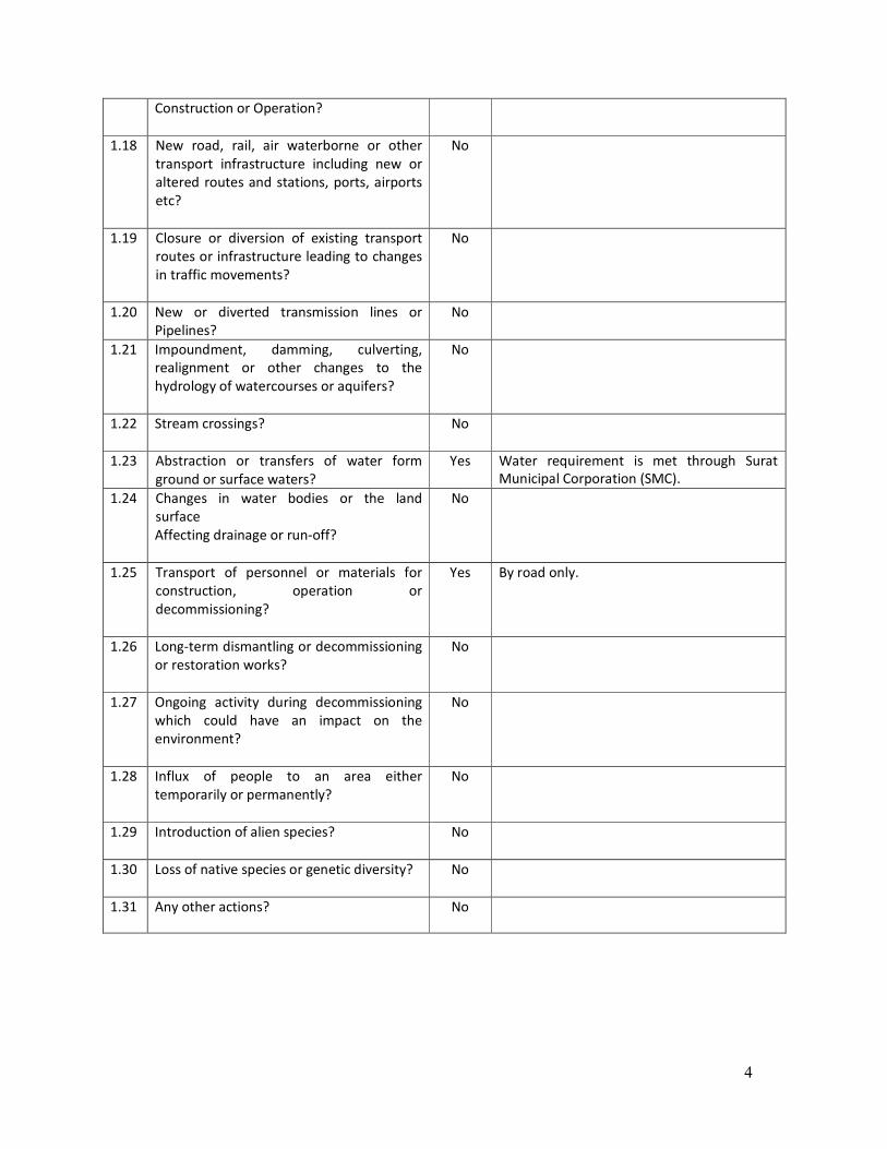
ANNEXURE – 1
LIST OF PRODUCTS WITH THEIR PRODUCTION CAPACITY
Sr.
No. Product Name
Production
Existing Proposed Total
MT/Month MT/Month
1 Nytrosyl Sulphuric Acid (from Sulfur) * 132.08 132.08
2
Nytrosyl Sulphuric Acid (from Sodium Thio
Sulphate Solution and Spent Acid
(H2SO4)) **
468 468
3.1 4-Methoxy Acetophenone 0 60
3.2 4-Methyl Acetophenone
4.1 Diethyl Ketone
0 100 4.2 Methyl Propyl Ketone
4.3 Dipropyl Ketone
4.4 Propiophenone
5 Alpha Nitro Napthalene 0 100
6 Alpha Napthylamine 0 165
7 Phenyl Alpha Naphthylamine (PANA) 0 90
8 Epichlorohydrin Based Polyamide resin 0 116
9 3,5-Dichloroaniline 0 50
10 Bis-(2-Chloroethyl)-amine 0 30
Total 600.08 1311.08
By Products
1 Sulphur 50.74 50.74
2 Sodium Sulphate 242.728 242.728
3 Di Ethyl Ketone Nil 79
4 Acetic Acid Nil 30.5

13
ANNEXURE – 2
PLANT LAYOUT

14
ANNEXURE – 3
MANUFACTURING PROCESS, CHEMICAL REACTION WITH MASS BALANCE
1. NITROSYL SULFURIC ACID (NSA) FROM SULFUR (OR SULFUR DIOXIDE GAS)
Process Description:
First make mix acid of Oleum 23 % and concentrate Nitric Acid . Charge Sulfur in to the mix
acid from this process reaction takes place and generation SO2 Gas (or charge Sulphur
Dioxide gas in to the mix acid). SO2 react with concentrate Nitric Acid and Oleum convert in
to Sulphuric A cid after this reaction product will be Nitrosyl Sulfuric Acid (NSA).
Reaction Mechanism
6 HNO3 + 2S 3N2O3 + 2SO3 + 3H2O
N2O3 + 2SO3 + H2O 2NOHSO4
6HNO3 + 8H2SO4 + 4SO3 + 2S 6NOHSO4 + 8H2SO4
OR
H2SO4 + HNO3 + SO2 NOHSO4 + H2SO4
Flow Chart
MIX ACID
Oleum 23 % (7590 Kg) or
Sulphuric Acid 98% [6604 kg]
Nitric Acid 98 % [7590 kg] Or
Nitric Acid 98 % [1764 kg]
10160 kg NSA
Sulphur [420 kg] Or
Sulphur Dioxide Gas [1792 kg]

15
Nytrosyl Sulphuric Acid from Sulfur
INPUT KG PROCESS KG OUTPUT
Oleum 23 % or
Sulphuric Acid 98 %
7590 or 6604
Mix Acid Vessel
10160 NSA
Nitric Acid 98 % 2151 or 1764 1 SO2
Sulphar or SO2 Gas 420 or 1792
Total 10161 10161 Total

16
PRODUCT [2]
NITROSYL SULPHURIC ACID (NSA) AND SULPHUR RECOVERY FROM SODIUM
THIOSUIPHATE SOLUTION
1. Process Description with Chemical Reaction:
Nytrosyl Sulphuric Acid from the spent sodium thio solution shall be manufactured only after
getting permission from the Central Pollution Control Board [i. e. utilization of the hazardous
wastes under Rule 11 of the Hazardous Waste (Management, Handling & Transboundary)
Rules, 2008].
Sulfur and Sodium Sulphate shall be generated, only from the manufacturing of Nytrosyl
Sulphuric Acid from Sodium Thio Sulphate Solution (used as a raw material).
Take Sodium Thiosuiphate Solution. Now take this solution in one vessel and add spent acid
in it, Reaction takes place and SO2 librates, Scrub this gas in another vessel which is having
mix acid of H2SO4 and HNO3.
Mix Acid Vessel which has scrubbed SO2 gas will make NITROSYL SULFURIC ACID [NSA].
SO2 + HNO3 NOHSO4
[NSA]
After completion of Spent Addition heat the solution till SO2 librates then cool the mass and
filter. Dry the residue to obtain SULPHUR.
Filtrate will be collected separately, neutralize this solution and make concentrate by
distillation water, then cool the mass, and Filter it.
Residue will be dried and Product will be SODIUM SULPHATE, Filtrate will be used again.
Na2S2O3 + H2SO4 SO2 + S + H2O + NA2SO4

17
Flowchart:

18
Nytrosyl Sulphuric Acid
INPUT KG PROCESS KG OUTPUT
INPUT KG PROCESS KG OUTPUT
Thio
Solutio
n 14000
Acidifica
tion
Vessel
2633.56 SO2
SO2 2633.56
NSA
Scrubber
13097.
48 NSA 40 %
Spent
H2SO4
(40 %) 8000
19366.4
4
Reaction
Mass
H2SO4
98 % 7862.32
HNO3
98 % 2601.6
Total 22000 22000 Total Total
13097.4
8
13097.
48 Total
Reacti
on
Mass
19366.
44
Filtration
1800
Sulfur
W/C
Sulfur
W/C 1800
Dryer
1420 Sulfur Dry
17566.4
4
Reaction
Mass 380
Water Evaporated
Total 1800 1800 Total
Total
19366.
44
19366.4
4 Total
Reacti
on
Mass
17566.
44
Neutraliz
ation
Vessel
564.52 CO2
Soda
Ash 1360
18361.9
2
Reaction
Mass
Total
18926.
44
18926.4
4 Total
Reacti
on
Mass
18361.
92
MEE &
Centrifug
e
6793
Sodium
Sulphate
11568
Condens
ate
Water
0.92
M. L. to
recycled
Total
18361.
92
18361.9
2 Total
19
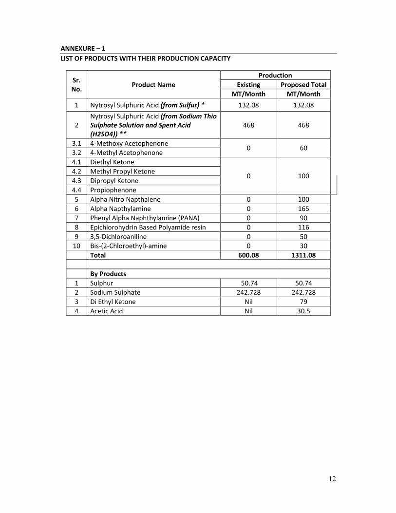
Mass Balance:
INPUT : kg/batch Kg/month Specific
Consumption
Thio Solution 14000.00 500248.90 1.069
Spent H2SO4 (40 %) 8000.00 285856.52 0.611
Soda Ash 1360.00 48595.61 0.104
H2SO4 98 % 7862.32 280936.93 0.600
HNO3 98 % 2601.60 92960.54 0.199
Total 33823.92 1208598.49
OUTPUT : kg/batch Kg/month
Sodium Sulphate 6793.00 242727.91
Condensate Water 11568.00 413348.52
M. L. to Recycled in MEE 0.92 32.87
NSA 40 % 13097.48 468000.00
Sulfur Dry 1420.00 50739.53
Water Evaporated 380.00 13578.18
CO2 564.52 20171.47
Total 33823.92 1208598.49

20
PRODUCT [3.1]
4- METHOXY ACETO-PHENONE
1. Process Description:
Catalyst 60. Kg is kept in stirred reactor. To this, total required Anisole 3459.54 kgs and Acetic
Anhydride 723.40 kgs, are added over a period of 1 hour under constant stirring. After closing the
reaction autoclave, the process temperature is raised to 120-130oC slowly and stepwise with
constant stirring and maintain for 4-5 hours. The reaction process is terminated by putting off the
heating. The autoclave was allowed to cool till the temperature of the mass drops down to below
50oC. The reaction mixture is drained out through the bottom drain valve of the autoclave in nutch
filter for separation of catalyst. Finally, reaction mixture is taken for filtration. The wet cake is
washed with small amount of anisole. The reaction mixture is subjected to fractional distillation to
separate all the components. Anisole is recovered and recycled; acetic acid is recovered of desired
grade. Finally 4-MAP is distilled out.
2. Reaction Mechanism

21
3. Flow Chart
INPUT Kg
Acetylation
Reaction
OUTPUT Kg
Anisol 3459.54 Reaction Mass 4242.94
Catalyst 18.00
Catalyst [Recover] 42.00
Acetic Anhydride 723.40
Total 4242.94 Total 4242.94
INPUT Kg
Filtration
OUTPUT Kg
Reaction Mass 4242.94 Catalyst [Recover] 42.00
Reaction Mass 4182.94
Catalyst to TSDF 18.00
Total 4242.94 Total 4242.94
INPUT Kg
Distillation -1
OUTPUT Kg
Reaction Mass 4182.94 Acetic Acid (By Product) 401.00
loss 24.50
Anisol 2679.30
loss 34.13
Reaction Mass 1044.01
Total 4182.94 Total 4182.94
INPUT Kg
Distillation-2
OUTPUT
Reaction Mass 1044.01 4 Methoxy
acetophenone 1000.00
loss 6.53
Residue 37.48
Total 1044.01 Total 1044.01

22
Mass Balance
4 - Methoxy Acetophenone
Sr. No. Input Kg Output Kg
1 Anisol 3459.54 4 - Methoxy Acetophenone 1000
2 Acetic anhydride 723.4 loss 6.53
3 catalyst 60 Catalyst 42
4 Catalyst - Loss 18
5 Acetic Acid 405
6 Loss 20.5
7 Anisol 2679.3
8 Loss 34.13
9 Residue to TSDF 37.48
TOTAL 4242.94 Total 4242.94

23
PRODUCT [3.2]
4-Methyl Acetophenone
process Description:
Catalyst is kept in stirred reactor. To this, total required Toluene and Acetic Anhydride, are added
over a period of 2 hour under constant stirring. After closing the reaction autoclave, the process
temperature is raised to 120-130oC slowly and stepwise with constant stirring and maintain for 4-5
hours. The reaction process is terminated by putting off the heating. The autoclave was allowed to
cool till the temperature of the mass drops down to below 50oC. The reaction mixture is drained out
through the bottom drain valve of the autoclave in nutch filter for separation of catalyst. Finally,
reaction mixture is taken for filtration. The reaction mixture is subjected to fractional distillation to
separate all the components. Toluene is recovered and recycled; acetic acid is recovered of desired
grade. Finally 4-MAP is distilled out.
Reaction Mechanism

24
Flowchart
INPUT Kg Acetylation
Reaction
OUTPUT Kg
Toluene 24029.9 Reaction Mass 26763.30
Catalyst 18.00
Catalyst [Recover] 42.00
Water 9.20
Acetic Anhydride 2664.20
Total 26763.30 Total 26763.30
INPUT Kg
Filtration
OUTPUT Kg
Reaction Mass 26763.30 Catalyst [Recover] 42.00
Catalyst to TSDF 18.00
Reaction Mass 26703.30
Total 26763.30 Total 26763.30
INPUT Kg Distillation -1 OUTPUT Kg
Reaction Mass 26703.30 4 Methyl
acetophenone (Crude) 1050.00
Toluene 22144.00
loss 1165.00
Acetic anhydride 1812.70
Acetic Acid 505.02
Loss 26.58
Total 26703.30 Total 26703.30
INPUT Kg
Distillation -2
OUTPUT Kg
4 Methyl
acetophenone 1050.00
4 Methyl
acetophenone 1000.00
[Crude] Loss 6.53
Residue 43.47
Total 1050.00 Total 1050.00
25
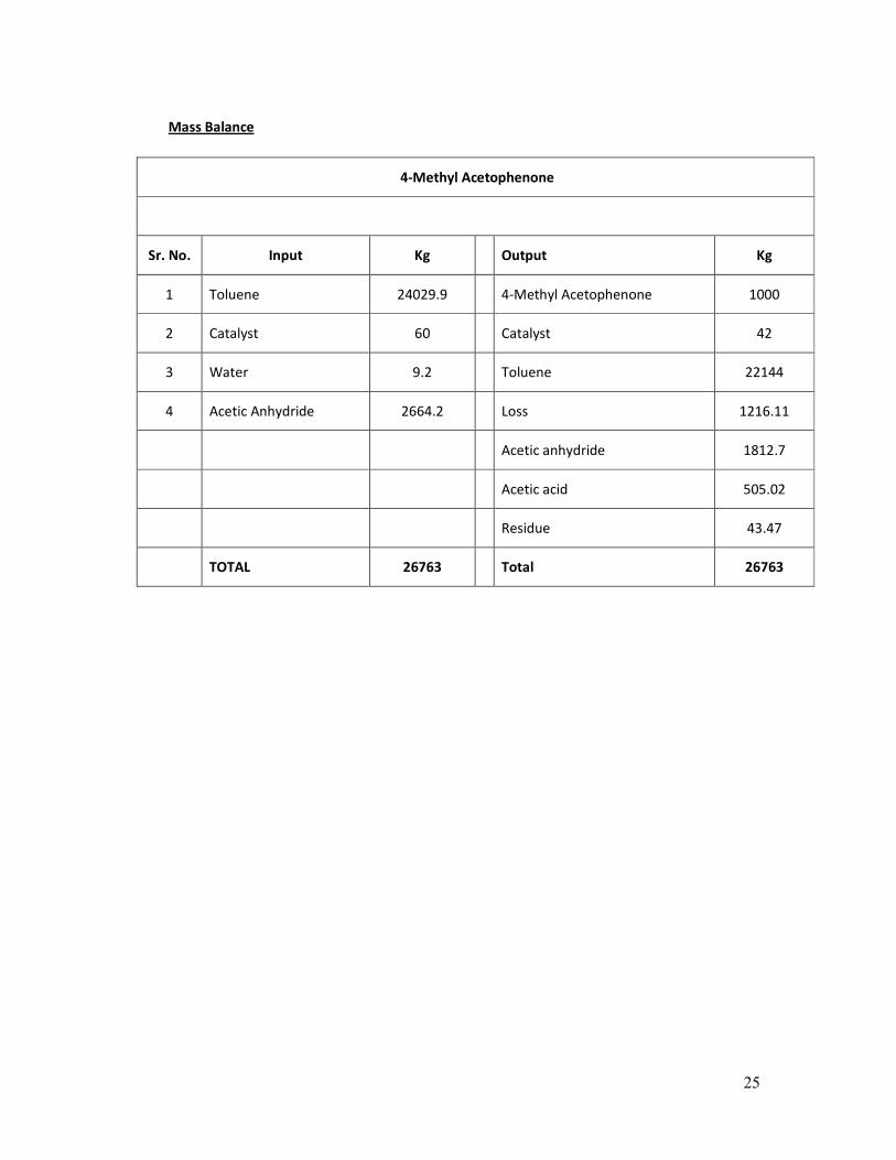
Mass Balance
4-Methyl Acetophenone
Sr. No. Input Kg Output Kg
1 Toluene 24029.9 4-Methyl Acetophenone 1000
2 Catalyst 60 Catalyst 42
3 Water 9.2 Toluene 22144
4 Acetic Anhydride 2664.2 Loss 1216.11
Acetic anhydride 1812.7
Acetic acid 505.02
Residue 43.47
TOTAL 26763 Total 26763

26
PRODUCT [4.1]
Diethyl Ketone
Process Description
Propionic acid is vapourized in the vapourizer and feed to catalyst bed at higher temperature to get
the desired product i.e. Diethyl Ketone which is found in the vapour form. The vapour is cool down
in the heat exchanger. Carbon Dioxide is vent off and Water is separate out from DEK through phase
separation.
Reaction Mechanism
1. F
lowchart
INPUT KG PROCESS KG OUTPUT
Propionic Acid 1.76
Pyrolysis Reaction
1 Diethyl Ketone
0.54 CO2 gas
0.22 Water
Total 1.76 1.76 Total
Pyrolysis
Catalyst
Propionic acid Diethyl Ketone
+ CO2+ H2O
Carbon
Dioxide Water

27
Mass Balance
4.1…... Diethyl Ketone
Sr. No. Input Kg Output Kg
1 Propionic Acid 176000 Product 100000
CO2 gas 54000
Water 22000
TOTAL 176000 Total 176000

28
PRODUCT [4.2]
Methyl Propyl Ketone
Process Description
Butyric acid and Acetic acid are vapourized in the vapourizer in equal propotion and feed to catalyst
bed at higher temperature to get the desired product i.e. Methyl propyl ketone which is found in the
vapour form. The vapour is cool down in the heat exchanger. Carbon Dioxide is vent off and Water is
separate out from MPK through phase separation.
Reaction Mechanism
Pyrolysis
Catalyst
Butyric acid Methyl propyl
Ketone
+ CO2 + H2O
Carbon
Dioxide
Water
+
Acetic acid

29
Flowchart
INPUT KG PROCESS OUTPUT KG
Butyric acid 1.03
Pyrolysis
Reaction
1 MPK
Acetic acid 0.69 0.51 CO2 GAS
0.21 WATER
Total 1.72 1.72
Mass Balance
Methyl Propyl Ketone
Sr. No. Input Kg Output Kg
1 Butyric acid 103000 Methyl Propyl Ketone 100000
2 Acetic Acid 69000 CO2 Gas 51000
Water 21000
TOTAL 172000.00 Total 172000

30
PRODUCT [4.3]
Dipropyl Ketone
Process Description
Butyric acid is vapourized in the vapourizer and feed to catalyst bed at higher temperature to get the
desired product i.e. Dipropyl Ketone which is found in the vapour form. The vapour is cool down in
the heat exchanger. Carbon Dioxide is vent off and Water is separate out from DPK through phase
separation.
Reaction Mechanism
Flowchart
INPUT KG PROCESS KG OUTPUT
Butyric acid 1.54
Pyrolysis
Reaction
1 DPK
0.4 CO2 GAS
0.14 WATER
Total 1.54 1.54 Total
Pyrolysis
Catalyst
Butyric acid Dipropyl
Ketone
+ CO2+ H2O
Carbon
Dioxide Water

31
Mass Balance
4.3…... Dipropyl Ketone
Sr. No. Input Kg Output Kg
1 Butyric Acid 154000 Dipropyl Ketone 100000
Water 14000
CO2 Gas 40000
TOTAL 154000.00 Total 154000.00
32
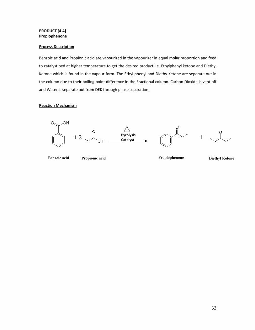
PRODUCT [4.4]
Propiophenone
Process Description
Benzoic acid and Propionic acid are vapourized in the vapourizer in equal molar proportion and feed
to catalyst bed at higher temperature to get the desired product i.e. Ethylphenyl ketone and Diethyl
Ketone which is found in the vapour form. The Ethyl phenyl and Diethy Ketone are separate out in
the column due to their boiling point difference in the Fractional column. Carbon Dioxide is vent off
and Water is separate out from DEK through phase separation.
Reaction Mechanism
Pyrolysis
Catalyst
Benzoic acid Propiophenone
+ 2
Propionic acid
+
Diethyl Ketone

33
Flowchart
INPUT KG PROCESS OUTPUT KG
Benzoic acid 0.51
Pyrolysis
Reaction
0.56 Propiophenone
Propionic acid 0.76 0.44 DEK
0.18 CO2 GAS
0.09 WATER
Total 1.27 1.27 Total
Mass Balance
4.4……. Propiophenone
Sr. No. Input Kg Output Kg
1 Benzoic acid 54212.598 Propiophenone 59528
2 Propionic acid 80787.402 Diethyl Ketone 46772
CO2 Gas 19134
Water 9567
TOTAL 135000 Total 135000

34
PRODUCT [5]
ALPHA NITRONAPHTHALENE
1. Process Description
Nitric Acid 60%is taken in the reactor and Naphthaleneis charged into reactor at desired flow rate
and temperature. Output from the Reaction will contain 1-Nitronaphthalene [ANN] along with Dilute
Nitric Acid 40-42% [Spent Acid].
Spent Acid is then removed through layer separation and then top organic mass is separate out.
Organic layer is nothing but our finished product i.e. Alpha Nitro Naphthalene.
2. Reaction Mechanism
3. Flow Chart
INPUT KG PROCESS KG OUTPUT
Naphthalene 520.00
Nitration
694.00 1-Nitro Naphthalene
Nitric Acid 60% 853.13 642.00 Dilute acid for recover [42%]
37.13 Evaporation loss
Total 1373.13 1373.13 Total
35
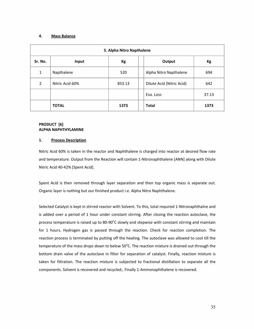
4. Mass Balance
5. Alpha Nitro Napthalene
Sr. No. Input Kg Output Kg
1 Napthalene 520 Alpha Nitro Napthalene 694
2 Nitric Acid 60% 853.13 Dilute Acid (Nitric Acid) 642
Eva. Loss 37.13
TOTAL 1373 Total 1373
PRODUCT [6]
ALPHA NAPHTHYLAMINE
1. Process Description
Nitric Acid 60% is taken in the reactor and Naphthalene is charged into reactor at desired flow rate
and temperature. Output from the Reaction will contain 1-Nitronaphthalene [ANN] along with Dilute
Nitric Acid 40-42% [Spent Acid].
Spent Acid is then removed through layer separation and then top organic mass is separate out.
Organic layer is nothing but our finished product i.e. Alpha Nitro Naphthalene.
Selected Catalyst is kept in stirred reactor with Solvent. To this, total required 1-Nitronaphthalne and
is added over a period of 1 hour under constant stirring. After closing the reaction autoclave, the
process temperature is raised up to 80-90oC slowly and stepwise with constant stirring and maintain
for 1 hours. Hydrogen gas is passed through the reaction. Check for reaction completion. The
reaction process is terminated by putting off the heating. The autoclave was allowed to cool till the
temperature of the mass drops down to below 50oC. The reaction mixture is drained out through the
bottom drain valve of the autoclave in filter for separation of catalyst. Finally, reaction mixture is
taken for filtration. The reaction mixture is subjected to fractional distillation to separate all the
components. Solvent is recovered and recycled;. Finally 1-Aminonaphthalene is recovered.

36
2. Reaction Mechanism
Step : 1 : Nitration Of Naphthalene :
Step : 2 : Reduction Of Alpha Nitro Naphthalene :

37
3. Flow Chart
INPUT KG PROCESS KG OUTPUT
Naphthalene 520.00 Nitration 694.00 1-Nitro Naphthalene
Nitric Acid 60% 853.13 642.00 Dilute acid for recover [42%]
37.13 Evaporation loss
Total 1373.13 1373.13 Total
INPUT Kg
Hydrogenation
Kg OUTPUT
1-Nitro Naphthalene 694.00 1738.07 Reaction Mass
IPA / METHANOL 950.00
Hydrogen 24.07
Catalyst 70.00
Total 1738.07 1738.07 Total
INPUT Kg
Filtration
Kg OUTPUT
Reaction Mass 1738.07 60.00 Catalyst [recover]
10.00 Catalyst to TSDF
1668.07 Filtrate Reaction Mass
Total 1738.07 1738.07 Total
INPUT Kg
Distillation
Kg OUTPUT
Reaction Mass 1668.07 903.00 IPA / METHANOL OR
47.00 loss
144.42 Distilled water
545.00 Product ANA
28.65 Residue
Total 1668.07 1668.07 Total

38
4. Mass Balance
6. Alpha Naphthylamine
By Using IPA / Methanol
Sr. No. Input Kg Output Kg
1 Napthalene 520 Alpha Naphthylamine 545
2 Nitric Acid 60% 853.13 Dilute Acid (Nitric Acid) 642
3 IPA / Methanol 950 Eva Loss 37.13
4 Hydrogen 24.07 Catalyst 60
5 catalyst 70 Catalyst Loss 10
6 IPA / Methanol 903
7 Loss 47
8 Distilled Water 144.42
9 Residue to TSDF Site 28.65
TOTAL 2417.20 Total 2417.20

39
Using Aniline / ODCB as a Solvent :-
INPUT KG PROCESS KG OUTPUT
Naphthalene 520.00
Nitration
694.00 1-Nitro Naphthalene
Nitric Acid 60% 853.13 642.00 Dilute acid for recover [42%]
37.13 Evaporation loss
Total 1373.13 1373.13 Total
INPUT Kg
Hydrogenation
Kg OUTPUT
1-Nitro Naphthalene 694.00 2088.07 Reaction Mass
ANILINE/ODCB 1300.00
Hydrogen 24.07
Catalyst 70.00
Total 2088.07 2088.07 Total
INPUT Kg
Filtration
Kg OUTPUT
Reaction Mass 2088.07 60.00 Catalyst [recover]
10.00 Catalyst to TSDF
2018.07 Filtrate Reaction Mass
Total 2088.07 2088.07 Total
INPUT Kg
Distillation
Kg OUTPUT
Reaction Mass 2018.07 1274.00 ANILINE/ODCB
26.00 loss
144.42 Distilled water
545.00 Product ANA
28.65 Residue
Total 2018.07 2018.07 Total

40
5. Mass Balance
6. Alpha Naphthylamine
By Using Aniline / ODCB
Sr. No. Input Kg Output Kg
1 Napthalene 520 Alpha Naphthylamine 545
2 Nitric Acid 60% 853.13 Dilute Acid (Nitric Acid) 642
3 Aniline / ODCB 1300 Eva. Loss 37.13
4 Hydrogen 24.07 Catalyst 60
5 catalyst 70 Catalyst Loss 10
6 Aniline / ODCB 1274
7 Loss 26
8 Distilled Water 144.42
9 Residue to TSDF Site 28.65
TOTAL 2767.20 Total 2767.20

41
PRODUCT [7]
PHENYL ALPHA NAPHTHYLAMINE [PANA]
1. Process Description
Selected Catalyst is kept in stirred reactor with Aniline. To this, total required 1-Aminonaphthalne
4000 kg is added over a period of 1 hour under constant stirring. After closing the reactor, the
process temperature is raised up to 280oC slowly and stepwise with constant stirring. Ammonia Gas
will liberate during reaction which is scrubbed in Scrubber. The reaction process is terminated by
putting off the heating. The reactor was allowed to cool till the temperature of the mass drops down
to below 50oC. The reaction mixture is transfer to distillation reactor and fractional distillation is
done through which Aniline, Low Boiler and PANA will distilled out. Residue will be discharged from
bottom which will be disposed to solid waste disposal site.
2. Reaction Mechanism

42
3. Flow Chart
INPUT KG PROCESS KG OUTPUT
Aniline [Fresh] 2600.00 Condensation 9724.50 Reaction Mass
Aniline (Recovered] 3500.00 475.50 Ammonia to Scrubber
Alpha Naphthylamine 4000.00
Catalyst 100.00
Total 10200.00 10200.00 Total
INPUT KG
Distillation
KG OUTPUT
Reaction Mass 9724.50 5600.00 Phenyl Alphanaphthylamine
3500.00 Aniline [Recovered]
21.50 Loss
3.00 Evaporation loss
600.00 Distillation Residue
Total 9724.50 9724.50 Total
4. Mass Balance
7. Phenyl Alpha Napthylamine
Sr. No. Input Kg Output Kg
1 Aniline (Fresh) 2600 Phenyl Alpha Napthylamine 5600
2 Aniline (Recovered) 3500 Ammonia 475.5
3 Alpha Napthylamine 4000 Aniline 3500
4 Catalyst 100 Eva. Loss 24.5
Distillation Residue 600
TOTAL 10200 Total 10200
43
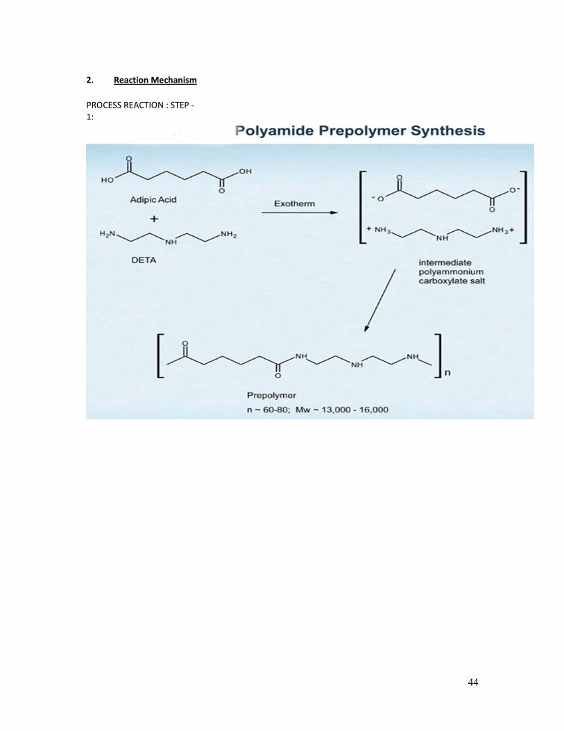
PRODUCT [8]
EPICHLOROHYDRIN BASED POLY AMIDE RESIN
1. Process Description
Take Diethylene triamine (DETA) in the reactor and Charge Adipic Acid in DETA . Heat the reaction
Mixture to 125Deg.C. Maintain temperature 3 Hours. Now, Cool the reaction mass 90 Deg.C.
After that Dilute the reaction Mass with water and Add Epichlorohydrin in above reaction mass and
stir 45 mins.
Reaction take Place and Product will be EPICHLOROHYDRIN BASED POLY AMIDE RESIN.
44
2. Reaction Mechanism
PROCESS REACTION : STEP -
1:
45
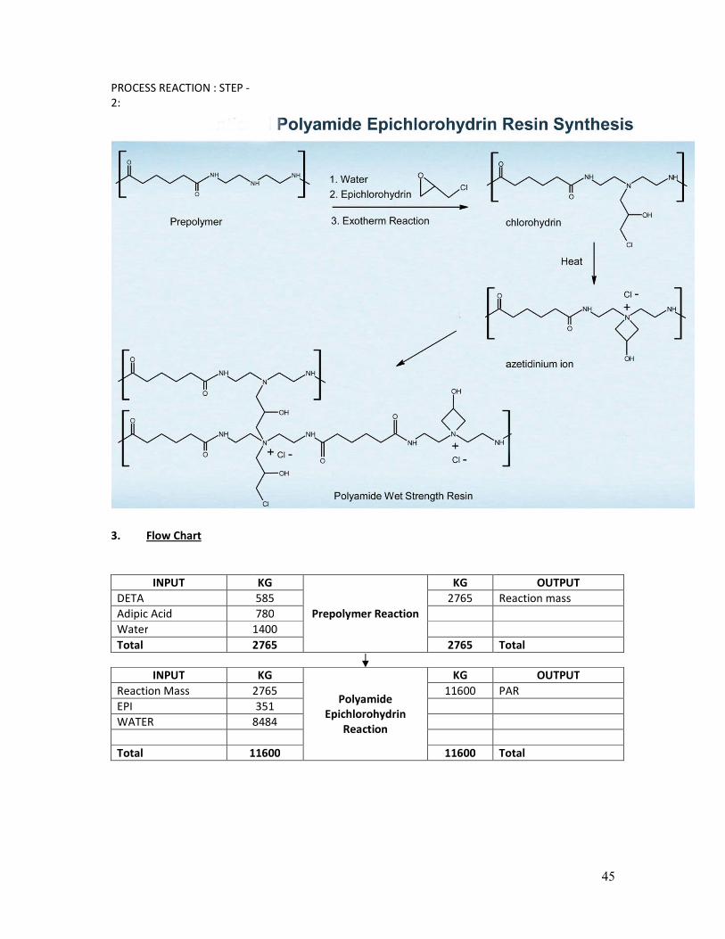
PROCESS REACTION : STEP -
2:
3. Flow Chart
INPUT KG
Prepolymer Reaction
KG OUTPUT
DETA 585 2765 Reaction mass
Adipic Acid 780
Water 1400
Total 2765 2765 Total
INPUT KG
Polyamide
Epichlorohydrin
Reaction
KG OUTPUT
Reaction Mass 2765 11600 PAR
EPI 351
WATER 8484
Total 11600 11600 Total

46
4. Material Balance
ECH based Polyamide Resin
Sr. No. Input Kg Output Kg
1 DETA 585 ECH based Polyamide Resin 11600
2 Adipic Acid 780
3 Water 9884
4 EPI 351
TOTAL 11600 Total 11600

47
PRODUCT [9]
3,5 – Dichloroaniline
Process Description
PNA is charged into reactor containing desired quantity of MCB as a solvent. PNA is chlorinated to
2,6 DCPNA with the help of chlorine gas and HCl is obtained as a byproduct.
2,6 DCPNA in MCB is then diazotized with the help of Nitrosyl sulfuric acid at low temperature.
Obtained reaction mass is then separate out into two layer i.e. 1. Organic layer consist MCB and
trace amount of organic impurities and 2. Aqueous layer consist Diazo of 2,6 DCPNA. MCB is recycle
for next chlorination.
This Aqueous layer then drawn into solution of Formaldehyde to give 3,5 DCNB. Here spent acid is
separate out and used for generation of NSA.
3,5 DCNB then reduced by charging it into the polysulfide solution made by Caustic lye and sulphur.
After 5-6 hours of reflux. Reaction mass is cool down and then phase separation is carried out. In
Organic layer, we obtain Crude 3,5-DCA and Sodium thio solution is obtained in aqueous layer which
can be sale.
Crude 3,5 DCA is further distilled out to achieve better quality.
48
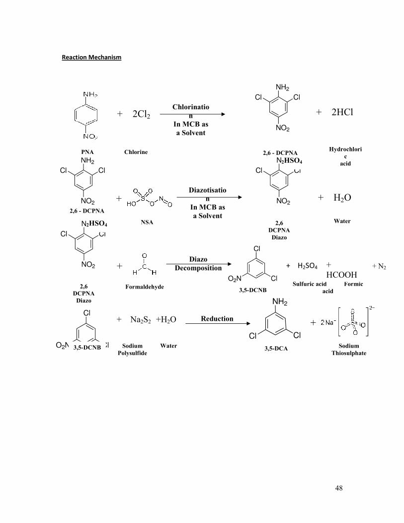
Reaction Mechanism
+ 2Cl2 Chlorinatio
n
In MCB as
a Solvent
+ 2HCl
PNA Chlorine Hydrochlori
c
acid
2,6 - DCPNA
2,6 - DCPNA
+
NSA
Diazotisatio
n
In MCB as
a Solvent
2HSO4
+ H2O
Water 2HSO4
+
2,6
DCPNA
Diazo
2,6
DCPNA
Diazo
Formaldehyde
Diazo
Decomposition
3,5-DCNB
+ H2SO4
Sulfuric acid Formic
acid
3,5-DCNB
+Reduction
Sodium
Polysulfide 3,5-DCA
+ Na2S2 +H2O
Sodium
Thiosulphate
Water
+
HCOOH
+ N2

49
Flowchart
INPUT KG PROCESS KG OUTPUT
PNA 666
Chlorination
4329 Reaction Mass
Chlorine 685 352 HCL to Scrubber
MCB 3330
Total 4681 4681 Total
INPUT KG
Diazotization
KG OUTPUT
Reaction Mass 4329 5944 Reaction Mass
NSA 1200
NSA [RECOVER] 415
Total 5944 5944 Total
INPUT KG
Layer Saperation
KG OUTPUT
Reaction Mass 5944 3444 MCB **
2500 2,6-DCPNA DIAZO
Total 5944 5944 Total
INPUT KG
Diazo
Decomposition
KG OUTPUT
2,6-DCPNA DIAZO 2500 751 3,5-DCNB
HCHO 495 2135 Spent Acid
109 N2
Total 2995 2995 Total
3,5-DCNB 751
Reduction
4261 Reaction Mass
Sulphur 405
Caustic Lye 48% 1055
water 2050
Total 4261 4261 Total
Reaction Mass 4261
Layer Separation
575 Organic layer
Wash Water 600 3681 Thio layer for sale
625 Washing Layer for MEE
Total 4861 4861 Total
Reaction Mass 575
Distillation
477 3,5 DCA
98 Residue TO TSDF Site
Total 575 575 Total
MCB RECOVERY **

50
INPUT KG
Washing
KG OUTPUT
MCB 3444 3429 MCB
NSA 400 415 NSA [recover]
Total 3844 3844 Total
INPUT KG
Distillation
KG OUTPUT
MCB 3429 3243 MCB
118 MCB vent Loss
68 Residue
Total 3429 3429 Total

51
Mass Balance
9. 3,5-Dichloroaniline
Sr. No. Input Kg Output Kg
1 PNA 666 3,5-Dichloroaniline 477
2 Chlorine 685 Gaseous Emission (HCl) 352
3 MCB 3330 MCB 3243
4 NSA 2015 Loss 118
5 HCHO 495 Spent Acid (H2SO4) 2135
6 Sulphur 405 N2 109
7 Caustic Lye 1055 Thio Layer 3661
8 Water 2650 Residue 166
NSA 415
Effluent to ETP 625
TOTAL 11301 Total 11301

52
PRODUCT [10]
Bis-(2-Chloroethyl)-amine Hydrochloride
Process Description
Diethanolamine is charged into the reactor having desired quantity of Ethylene dichloride as a
solvent. Then charge Thionyl chloride into it. Reaction is exothermic. After completion of reaction,
reaction mass is cool down to room temperature and then filtered. Mother liquor consisting
Ethylene dichloride is recycle where as sulfur dioxide and hydrochloric acid gas fumes are scrubbed
in appropriate scrubbers.
Reaction Mechanism
Ethylene
Dichlorid
e
Diethanol
amine
Bis-(2-Chloroethyl)-
amine
+ 2SO2 + HCl
Sulfur Dioxide Hydrochlori
c
acid
+ 2SOCl2
Thionyl
Chloride

53
Flowchart
INPUT KG PROCESS KG OUTPUT
DEA 590.00
Condensation
2000.00 Reaction Mass
Thionyl Chloride 1340.00 204.00 HCl to Scrubber
Ethylene Dichloride
[Recovered] 950.00 716.00 SO2 to Scrubber
Ethylene Dichloride [Fresh] 50.00 10.00 Evaporation Loss to Scrubber
Total 2930.00 2930.00 Total
Reaction Mass 2000.00
Filtration
1000.00 Bis-(2-Chloroethyl)-Amine HCl
950.00 EDC [Recovered]
50.00 Loss
Total 2000.00 2000.00 Total
Mass Balance
10. Bis-(2-Chloroethyl)-amine Hydrochloride
Sr. No. Input Kg Output Kg
1 DEA 590 Bis-(2-Chloroethyl)-amine
Hydrochloride 1000
2 Thionyl Chloride 1340 HCl 204
3 Ethylene Dichloride (Recovered) 950 SO2 716
4 Ethylene Dichloride (Fresh) 50 Eva Loss 60
EDC 950
TOTAL 2930 Total 2930

54
ANNEXURE-IV
WATER CONSUMPTION AND WASTEWATER GENERATION
Existing
Sr. No.
Description Water Consumption Waste Water Generation
KL/Day KL/Day
1 Cooling 20.0 1.5
2 Washing 0.5 0.5
Total Industrial 20.5 2.0
3 Domestic 5.0 5.0
Grand Total
25.5 (Fresh: 11.5 KL/Day
+ Recycle: 14 KL/Day)* 7.0
Note :-* 14 KL/day of Condensate water is generated only from the manufacturing of Nytrosyl
Sulphuric Acid (from spent sodium thio sulfate solution and Spent H2SO4 (used as raw materials)),
otherwise only fresh water is used in to Cooling Tower.
Source of Water: SMC
Total after Proposed Expansion:
Sr. No.
Description Water Consumption Waste Water Generation
KL/Day KL/Day
1 Process 13.0 2.0
2 Cooling 30.0 2.0
3 Washing 2.0 2.0
4 Scrubber 10.0 8.0
Total Industrial 55.0 14.0
5 Domestic 10.0 10.0
Grand Total 65.0 24.0
Note :- * For the first time 65 KL/Day of fresh water shall be use, than after 14 KL/Day
condensate water, 14 KL/Day treated effluent and 37 KL/Day of fresh water shall
be used.
** The Condensate water is generated only from the manufacturing of Nytrosyl
Sulphuric Acid (from spent sodium thio sulfate solution and Spent H2SO4)
Source of Water: SMC

56
Water Balance Diagram (Existing):
Note :-* The Condensate water is generated only from the manufacturing of Nytrosyl Sulphuric Acid from spent sodium thio sulfate solution
and Spent H2SO4 (used as raw materials), otherwise only fresh water is used in to Cooling Tower.
Source of Water: SMC
Raw Water (11.5 KL/Day)
Domestic 5 KL/Day Cooling 20 KL/Day
Process
(Condensate water
From MEE) *
ETP 2 KL/Day
14 KL/Day
Domestic Utilities
To Septic Tank / Soak
Pit 5 KL/Day
Use for gardening purpose. About 500
Sq. meter area is provided for gardening
purpose with in Factory premises.
Washing 0.5 KL/Day
6 KL/Day 5 KL/Day
1.5 KL/Day
0.5 KL/Day
0.5 KL/Day
Storage Tank
15 KL
14 KL/Day

57
WATER BALANCE DIAGRAM – PROPOSED TOTAL
Note :- * For the first time 65 KL/Day of fresh water shall be use, than after 14 KL/Day condensate water, 14 KL/Day treated effluent and 37 KL/Day of fresh
water shall be used.
** The Condensate water is generated only from the manufacturing of Nytrosyl Sulphuric Acid (from spent sodium thio sulfate solution and Spent
H2SO4)
Raw Water -65 KL/Day
Domestic
10 KL/Day
Cooling
Condensate water from Process (only
from manufacturing of Nytrosyl
Sulphuric Acid (from spent sodium
thio sulfate solution and Spent
H2SO4) )
ETP
14 KL/Day
14 KL/Day
Domestic
Utilities
To Septic Tank /
Soak Pit System
10 KL/Day
Reuse for utilities
Washing
30 KL/Day
10 KL/Day
2 KL/Day
2 KL/Day
2 KL/Day Storage Tank
14 KL/Day
Process
13 KL/Day
Scrubber
10 KL/Day
8 KL/Day
14 KL/Day
Industrial – 55 KL/Day
(14 KLD recycle condensate water + 14 KLD
treated effluent + 27 KLD Fresh Water)
Domestic
14 KL/Day
2 KL/Day

58
ANNEXURE-V:
EXISTING ETP DETAILS & DIAGRAM
DETAILS OF EFFLUENT TREATMENT PLAN - EXISTING
We have installed Effluent Treatment Plant having primary and tertiary treatment facilities for the
treatment of effluent generated from the cooling tower blow down and floor washing.
Mostly the effluent is neutral in nature, however pH correction is done if required in primary
treatment Plant.
Raw industrial effluent from the industrial unit is collected in collection-cum-equalization tank.
Lime and Acid solution tank is provided for the neutralization (if required) of industrial effluent.
Than the neutralized effluent is sent to nutch filter to remove the SS load in the form of ETP
sludge, Filtrate effluent is collected in to primary treated effluent collection tank and the treated
effluent is used for gardening purpose within factory premises after passing through Dual Media
Filter. About 500 Sq. Meter area is provided for gardening purpose.
The dewatered sludge from Nutch Filter is collected and packed in HDPE / Plastic bags and stored
in a proper solid / hazardous waste storage area.
The specification of ETP is as under …
ETP Flow Rate: 2 KL/Day – from cooling tower blow down and floor washing
No. Treatment Unit Qty. Brief Specification
1. Chemical Dosing Tank 2 Capacity: 100 Liters
MOC: HDPE
2. Collection / Equalization Tank (for cooling
tower blow down and Floor washing
effluent water)
1 Capacity: 5,000 Liters
MOC: HDPE chemical grade
3. Primary Settling Tank 1 Capacity: 5,000 Liters
MOC: HDPE chemical grade
4 Nutch Filter 1 Capacity: 2 m2
MOC: HDPE With Cloth
4 Primary treated effluent storage tank 1 Capacity : 5000 Liters
MOD: HDPE
5. Recycling Plant 1 Type: Dual media consisting of activated
carbon filter and sand filter
Size: 1.0 m Φ x 1 m
Capacity: 2 m3/hr
MOC: HDPE

59
DETAILS OF EFFLUENT TREATMENT PLAN – PROPOSED TOTAL
We have installed Effluent Treatment Plant having primary and tertiary treatment facilities for the
treatment of effluent generated from the from process, cooling, washing and scrubber.
Raw industrial effluent from the industrial unit is collected in collection-cum-equalization tank.
Lime and Acid solution tank is provided for the neutralization of industrial effluent. Than the
neutralized effluent is sent to nutch filter to remove the SS load in the form of ETP sludge, Filtrate
effluent is collected in to primary treated effluent collection tank.
The primary treated effluent first pass through sand filter, carbon filter and resin filter and given
ozone treatment and than reuse for utilities.
The dewatered sludge from Nutch Filter is collected and packed in HDPE / Plastic bags and stored
in a proper solid / hazardous waste storage area.
The specification of ETP is as under …
ETP Flow Rate: 14 KL/Day
No. Treatment Unit Qty. Brief Specification
1. Chemical Dosing Tank 2 Capacity: 100 Liters
MOC: HDPE
2. Collection / Equalization Tank
(for industrial effluent)
1 Capacity: 5,000 Liters
Retention time : 8.57 Hr
MOC: HDPE chemical grade
3. Primary Settling Tank 1 Capacity: 5,000 Liters
Retention time : 8.57 Hr
MOC: HDPE chemical grade
4 Nutch Filter 1 Capacity: 2 m2
MOC: HDPE With Cloth
4 Primary treated effluent storage tank 1 Capacity : 5000 Liters
MOC: HDPE
5. Sand Filter 1 Size: 1.0 m Φ x 1 m
Capacity: 2 m3/hr
MOC: HDPE

60
6. Carbon Filter 1 Size: 1.0 m Φ x 1 m
Capacity: 2 m3/hr
MOC: HDPE
7. Ozone Treatment 1 Capacity : 70 gm/hr
8. Treated Water Storage Tank 1 Capacity : 15 KL
MOC: HDPE

61
MODE OF DISPOSAL
INDUSTRIAL:
EXISTING :- 16 KL/Day Out of total 16 KL/Day of effluent ...
1. About 14 KL/Day of Condensate water (is generated only from
the manufacturing of Nytrosyl Sulphuric Acid( from spent sodium
thio sulphate solution and Spent H2SO4 (as a raw material)) is
recycled back in to cooling tower.
2. And remaining 2 KL/Day waste water generated from cooling
tower blow down and floor washing is treated in ETP and the
treated effluent is used for gardening purpose. About 500 Sq.
Meter area is provided for gardening purpose.
PROPOSED TOTAL :- 28 KL/Day Out of total 28 KL/Day of effluent ...
1. About 14 KL/Day of Condensate water is generated only from the
manufacturing of Nytrosyl Sulphuric Acid( from spent sodium thio
sulphate solution and Spent H2SO4 (as a raw material)) is
recycled back in to cooling tower.
2. And remaining 14 KL/Day waste water generated from process
(from manufacturing of 3, 5, DCA), cooling, washing & Scrubber
shall be treated in ETP and the treated effluent shall be reuse in
to utilities.
DOMESTIC :
EXISTING :- 5 KL/Day
The domestic waste water is discharged in to the septic tank / soak
pit system. PROPOSED TOTAL :- 10 KL/Day

62
1. Laboratory Treatability Studies
Effluent shall be generated from the Process (from the manufacturing of 3, 5 Di Chloro Aniline),
Cooling, Washing & Scrubber
The stream wise characteristic of effluent is as under…
No. Parameter Process
(3, 5 DCA) Cooling Washing Scrubber
Composite
Sample
Quantity, KL/Day 2 2 2 8 14
1. pH 4.9 7.9 7.1 8.8 7.87
2. Oil and Grease, mg/l 12 0.5 7.8 1.9 4.00
3. COD, mg/l 1350 160 450 980 840
4. BOD3, mg/l 240 45 90 190 162
5. Suspended Solids, mg/l 110 110 180 130 131
6. Phenolic Compound, mg/l BDL BDL BDL BDL BDL
7. TDS 1600 1200 1400 2200 1857
The above characteristics effluent shall be given Primary & Tertiary Treatment and will reuse in to
utilities after given ozonization treatment.
63
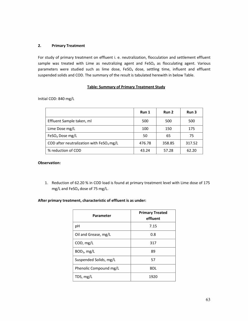
2. Primary Treatment
For study of primary treatment on effluent i. e. neutralization, flocculation and settlement effluent
sample was treated with Lime as neutralizing agent and FeSO4 as flocculating agent. Various
parameters were studied such as lime dose, FeSO4 dose, settling time, influent and effluent
suspended solids and COD. The summary of the result is tabulated herewith in below Table.
Table: Summary of Primary Treatment Study
Initial COD: 840 mg/L
Run 1 Run 2 Run 3
Effluent Sample taken, ml 500 500 500
Lime Dose mg/L 100 150 175
FeSO4 Dose mg/L 50 65 75
COD after neutralization with FeSO4 mg/L 476.78 358.85 317.52
% reduction of COD 43.24 57.28 62.20
Observation:
1. Reduction of 62.20 % in COD load is found at primary treatment level with Lime dose of 175
mg/L and FeSO4 dose of 75 mg/L.
After primary treatment, characteristic of effluent is as under:
Parameter Primary Treated
effluent
pH 7.15
Oil and Grease, mg/L 0.8
COD, mg/L 317
BOD3, mg/L 89
Suspended Solids, mg/L 57
Phenolic Compound mg/L BDL
TDS, mg/L 1920

64
The primary treated effluent shall be given tertiary treatment by passing through sand filter, carbon
filter and resin filter. The characteristics of tertiary treated effluent shall be as under ….
Parameter Tertiary Treated
effluent
pH 7.10
Oil and Grease, mg/L BDL
COD, mg/L 302
BOD3, mg/L 75
Suspended Solids, mg/L 30
Phenolic Compound mg/L BDL
TDS, mg/L 1920
The above characteristics effluent shall be reused in to utilities after given ozonization treatment.
The characteristics of final treated effluent shall be as under ….
Parameter Tertiary Treated
effluent
pH 7.10
Oil and Grease, mg/L BDL
COD, mg/L 65
BOD3, mg/L 20
Suspended Solids, mg/L 22
Phenolic Compound mg/L BDL
TDS, mg/L 1922

65
ANNEXURE-VI
DETAILS OF HAZARDOUS WASTE STORAGE, TREATMENT AND DISPOSAL
CAT.
NO.
TYPE OF SOLID /
HAZARDOUS
WASTES
SOURCE OF
WASTE
QUANTITY GENERATED
METHOD OF DISPOSAL
Existing Additional Proposed Total
5.1 Used Oil Plant and
Machinery
0.085 MT/Year
i. e.
100 Liters/Year
Nil 0.085 MT/Year
i. e.
100 Liters/Year
Collection / storage /
transportation / sent
to registered recycler
33.1 Discarded
containers /
barrels / liners/
Carboys/Bags
Raw
material
packaging
4.8 MT/Year
i. e.
600 Nos/Year
1.6 MT/Year
i. e.
200 Nos/Year
6.4 MT/Year
i. e.
800 Nos/Month
Collection / Storage /
Transportation /
Supplier / Sent To
Registered Recycler
35.3 ETP Sludge From ETP 100 Kg/Year 500 Kg/Year 600 Kg/Year Collection / Storage /
Transportation / Sent
To TSDF Site for
Secured Land Filling
29.5 Catalyst From
Process
Nil 4.1 MT/Month 4.1 MT/Month Collection / Storage /
Transportation /
Given Back to
Manufacturer for Re-
Generation
CATALYST SHALL BE GENERATED FROM THE MANUFACTURING OF 4 - METHOXY ACETOPHENONE, 4-METHYL
ACETOPHENONE & ALPHA NAPTHYLAMINE.
29.6 Spent Acid
(H2SO4)
---- 286 MT/Month Nil 286 MT/Month * Reception / Storage /
Transportation / used
as a raw material for
the manufacturing of
Nytrosyl Sulphuric Acid
(from Sodium Thio
Sulphate Solution and
Spent Acid (H2SO4))
From
manufacturi
ng of 3,5-
Dichloroanili
ne
Nil 224 MT/Month 224 MT/Month Reuse For The
Manufacturing of
Nytrosyl Sulphuric Acid
(From Sodium Thio
Sulphate Solution And
Spent Acid (H2SO4))
--- Sodium Thio
Sulfate Solution
---- 501 MT/Month Nil 501 MT/Month* Reception / usage /
storage /
transportation / use as
a raw material for the
manufacturing of
nytrosyl sulphuric acid
(from sodium thio
sulphate solution and
spent acid (H2SO4))

66
From
manufacturi
ng of 3,5-
Dichloroanili
ne
Nil 384 MT/Month 384 MT/Month Reuse For The
Manufacturing of
Nytrosyl Sulphuric Acid
(From Sodium Thio
Sulphate Solution And
Spent Acid (H2SO4)) / 3,
5 DCA
* Presently, Industry has applied under the rule 11 [i.e. utilization of the hazardous wastes as a supplementary
resource or for energy recovery, or after processing under rule 11 of the hazardous waste (management,
handling & transboundary) rules, 2008] for the reception (from actual generator) & usage of spent h2so4 &
spent sodium thio sulphate solution as a raw material for the manufacturing of nytrosyl sulphuric acid from
sodium thio sulphate solution & spent h2so4 on dated 9/3/2016. permission for the same is awaited.
Now as per proposed proposal, industry has proposed to manufacture about 50 MT/Day of 3, 5 Di Chloro
Aniline. From the manufacturing of this product Spent H2SO4 and Spent Sodium Thio Sulphate Solution shall be
generate. If industry will manufacture 3, 5 Di Chloro Aniline within premises, in such case industry will receipt
the balance quantity (as per manufacturing of 3, 5, Di Chloro Aniline quantity). If industry will manufacture 50
MT/Day of 3, 5 Di Chloro Aniline, than industry will receipt about balance quantity i. e. 62 MT/Month of Spent
H2 SO4 and 117 MT/Month of Spent Sodium Thio Sulphate Solution from actual generator.
29.4 Spent Solvent
(Anisol)
From the
manufacturi
ng of 4 -
Methoxy
Acetopheno
ne
Nil 161 MT/Month 161 MT/Month Collection / storage /
reuse in to next batch
in same process
29.4 Spent Solvent
(IPA OR
Methanol)
From
manufacturi
ng of Alpha
Napthylami
ne
Nil 274 MT/Month 274 MT/Month
Collection / storage /
reuse in to next batch
in same process
OR
Spent Solvent
(Aniline OR
ODCB)
From
manufacturi
ng of Alpha
Napthylami
ne
Nil 386 MT/Month 386 MT/Month
If industry will use IPA / methanol as a raw material for the manufacturing of alpha napthylamine, then IPA /
methanol shall be recovered, accordingly if industry will use aniline / ODCB, then only aniline / ODCB shall be
recovered.
29.4 Spent Solvent
(MCB)
From
manufacturi
ng 3,5-
Dichloroanili
ne
Nil 340 MT/Month 340 MT/Month Collection / Storage /
Reuse in to Next Batch
in same process
29.4 Spent Solvent
(Aniline)
From
manufacturi
ng Phenyl
Alpha
Naphthylam
ine
Nil 56.6 MT/Month 56.6 MT/Month Collection / Storage /
Reuse in to Next Batch
in Same Process

67
Details of Solid / Hazardous Waste Storage Area:
The Solid / Hazardous Waste Storage Area shall be 5.0 m x 5.5 m x 4.0 m in size, covered with
roof from the top, has impervious flooring with leachate collection system and is closed from
the four sides by boundary.
29.4 Spent Solvent
(Toluene)
From
manufacturi
ng of 4-
Methyl
Acetopheno
ne
Nil 1329 MT/Month 1329 MT/Month Collection / Storage /
Reuse in to Next Batch
in Same Process
29.4 Spent Solvent
(EDC)
From
manufacturi
ng of Bis-(2-
Chloroethyl)
-amine
Nil 28.5 MT/Month 28.5 MT/Month Collection / Storage /
Reuse in to Next Batch
in Same Process
29.1 Distillation
Residue
From
Process
Nil 38.5 MT/Month 38.5 MT/Month Collection / Storage /
Transportation / Sent
To Cement Industries
for Co-Processing of
CHWIF
Distillation residue generated from the manufacturing of 4-Methoxy Acetophenone, 4-Methyl Acetophenone,
Alpha Napthylamine, Phenyl Alpha Naphthylamine (Pana), 3,5-Dichloroaniline
--- Acetic
Anhydride
From
manufacturi
ng of 4-
Methyl
Acetopheno
ne
Nil 109 MT/Month 109 MT/Month Collection / Storage /
Transportation / Reuse
in to Next Batch in
Same Process

68
ANNEXURE – VII
DETAILS OF STACK AND VENT
The details of stack provided for stand by D. G. Set is as under…
FLUE GAS EMISSION
Sr.
No. Stack Attached To Stack Height
Fuel
Consumption Air Pollution Control System
A EXISTING
1. Thermo pack Unit
Cap.: 600 U Height-12 meter Natural Gas
82 SCM/Hr. As natural gas is used as a fuel,
adequate stack height is provided.
2. D. G. Set (Stand By)
Capacity: 250 KVA
Height-7 meter Diesel:
30 Liter/Hr. As diesel is used as a fuel,
adequate stack height is provided.
B ADDITIONAL
1. D. G. Set (Stand By)
Capacity: 365 KVA *
Height-7 meter Diesel:
45 Liter/Hr. As diesel shall be used as a fuel,
adequate stack height is provided.
* Industry shall remove the existing D. G. Set having capacity of 250 KVA and will install D. G.
Set having capacity of 365 KVA.
C PROPOSED TOTAL
1. Thermo pack Unit
Cap.: 600 U Height-12 meter Natural Gas:
82 SCM/Hr. As natural gas is used as a fuel,
adequate stack height is provided.
2. D. G. Set (Stand By)
Capacity: 365 KVA
Height-7 meter Diesel:
45 Liter/Hr. As diesel shall be used as a fuel,
adequate stack height is provided.
PROCESS GAS EMISSION
Sr.
No. Vent Attached To
Vent Height &
Diameter Pollutants Air Pollution Control System
A Existing
1. Acidification Vessels 12 meter SO2
Two Stage Scrubber (i.e. Ventury
Scrubber & Vertical column packed
scrubber) is provided. 2. Acidification Vessels
B Additional
There shall be no change in existing process gas emission.

69
The details of APCM are as under…
� TECHNICAL SPECIFICATION OF SCRUBBER:
1st
Stage :- VENTURY SCRUBBER
MOC : SS 316
Scrubbing Capacity : 200 Kg SO2 Gas/Hrs
Scrubbing Solution : Mix Acid of H2SO4 98% & HNO3 98%
Jet Capacity : 13 M3/Hrs 50 MTR Head
2nd
Stage :- VERTICAL SCRUBBER
MOCL : SS 316
Type : Pack column with Poll Ring
Scrubbing Capacity : 50 Kg SO2 Gas/Hrs
Scrubbing Solution : Mix Acid of H2SO4 98% & HNO3 98%
Pump Capacity : 5 M3/Hrs 50 MTR Head
3nd
Stage :- VERTICAL SCRUBBER
MOCL : SS 316
Type : Pack column with Poll Ring
Scrubbing Capacity : 50 Kg SO2 Gas/Hrs
Scrubbing Solution : Caustic Soda Lye Solution
Pump Capacity : 5 M3/Hrs 50 MTR Head

70
71
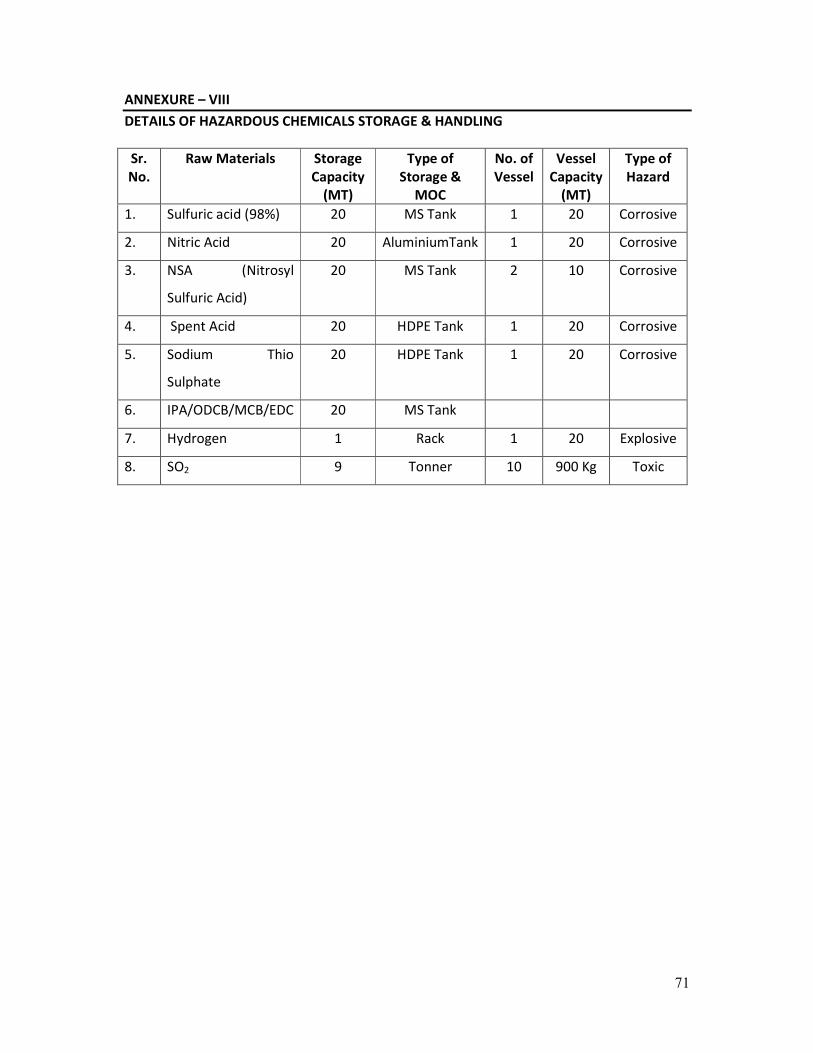
ANNEXURE – VIII
DETAILS OF HAZARDOUS CHEMICALS STORAGE & HANDLING
Sr.
No.
Raw Materials Storage
Capacity
(MT)
Type of
Storage &
MOC
No. of
Vessel
Vessel
Capacity
(MT)
Type of
Hazard
1. Sulfuric acid (98%) 20 MS Tank 1 20 Corrosive
2. Nitric Acid 20 AluminiumTank 1 20 Corrosive
3. NSA (Nitrosyl
Sulfuric Acid)
20 MS Tank 2 10 Corrosive
4. Spent Acid 20 HDPE Tank 1 20 Corrosive
5. Sodium Thio
Sulphate
20 HDPE Tank 1 20 Corrosive
6. IPA/ODCB/MCB/EDC 20 MS Tank
7. Hydrogen 1 Rack 1 20 Explosive
8. SO2 9 Tonner 10 900 Kg Toxic

72
ANNEXURE-IX
SOCIO-ECONOMIC IMPACTS
1) EMPLOYMENT OPPORTUNITIES
The manpower requirement for the proposed project is being expected to generate some
permanent jobs and secondary jobs for the operation and maintenance of plant. This will
increase direct / indirect employment opportunities and ancillary business development to
some extent for the local population.
This phase is expected to create a beneficial impact on the local socio-economic
environment.
2) INDUSTRIES
Required raw materials and skilled and unskilled laborers will be utilized maximum from the
local area. The increasing industrial activity will boost the commercial and economical status
of the locality, to some extent.
3) PUBLIC HEALTH
The company regularly examines, inspects and tests its emission from sources to make sure
that the emission is below the permissible limit. Hence, there will not be any significant
change in the status of sanitation and the community health of the area, as sufficient
measures have been taken and proposed under the EMP.
4) TRANSPORTATION AND COMMUNICATION
Since the existing factory is having proper linkage for the transport and communication, the
development of this project will not cause any additional impact.
In brief, as a result of the proposed project there will be no adverse impact on sanitation,
communication and community health, as sufficient measures have been proposed to be
taken under the EMP. The proposed project is not expected to make any significant change
in the existing status of the socio - economic environment of this region.

73
ANNEXURE-X
PROPOSED TORs
1. Project Description
• Justification of project.
• Promoters and their back ground
• Project site location along with site map of 5 km area and site details providing various
industries, surface water bodies, forests etc.
• Project cost
• Project location and Plant layout.
• Existing infrastructure facilities
• Water source and utilization including proposed water balance.
• List of Products and their capacity
• List of hazardous chemicals with their toxicity levels.
• Mass balance of each product along with the batch size
• Storage and Transportation of raw materials and products.
2. Description of the Environment and Baseline Data Collection
• Micrometeorological data for wind speed, direction, temperature, humidity and rainfall
in 5 km area.
• Study of Data from secondary sources.
• Existing environmental status Vis a Vis air, water, noise, soil in 5 km area from the project
site. For SPM, RSPM, SO2, NOx.
• Ground water quality at 5 locations within 5 km.
• Complete water balance
3. Socio Economic Data
• Existing socio-economic status, land use pattern and infrastructure facilities available in
the study area were surveyed.
4. Impacts Identification and Mitigatory Measures.
• Impact on air and mitigation measures including green belt
• Impact on water environment and mitigation measures
• Soil pollution source and mitigation measures
• Noise generation and control.
• Solid waste quantification and disposal.
• Control of fugitive emissions
5. Environmental Management Plan
• Details of pollution control measures
• Environment management team
• Proposed schedule for environmental monitoring including post project
6. Risk Assessment
• Details on storage facilities
• Identification of hazards

74
• Consequence analysis
• Recommendations on the basis of risk assessment done
• Disaster Management Plan.
7. Information for Control of Fugitive Emissions
8. Post Project Monitoring Plan for Air, Water, Soil and Noise.
9. Occupational Health and Safety Program for the Project.