Embed Size (px)
Citation preview

1
MRS Communications (2020), 10, 230–241 © Materials Research Society, 2020 doi:10.1557/mrc.2020.30
Prospective Article
Strain Mediated Magneto-Electric Interactions in Hexagonal Ferrite and Ferroelectric Coaxial
Nanofibers
Y. Liu,1,2 P. Zhou,1,2 J. Fu,1,3 M. Iyengar,1 N. Liu,2 P. Du,2 Y. Xiong,4 V. Moiseienko,1 W. Zhang,1 J.
Zhang,5 Z. Ma,2 Y. Qi,2 V. Novosad,4 T. Zhou,3 D. Filippov,6 T. Zhang,2 b) M.E. Page,7 G. Srinivasan1 a)
1Department of Physics, Oakland University, Rochester, MI 48309, USA
2Department of Materials Science and Engineering, Hubei University, Wuhan 430062, People’s Republic
of China
3College of Electronics and Information, Hangzhou Dianzi University, Hangzhou 310018, People’s
Republic of China
4Materials Science Division, Argonne National Laboratory, Argonne, IL 60439, USA
5College of Electrical and Information Engineering, Zhengzhou University of Light Industry, Zhengzhou
450002, People’s Republic of China
6Novgorod State University, Veliky Novgorod, Russia
7Materials and Manufacturing Directorate, Air Force Research Laboratory, Wright-Patterson Air Force
Base, Dayton, Ohio 45433, USA
Abstract
This report is on the synthesis by electrospinning of multiferroic core-shell nanofibers of strontium
hexaferrite and lead zirconate titanate or barium titanate and studies on magneto-electric (ME) coupling.
Fibers with well-defined core-shell structures showed order parameters in agreement with values for
nanostructures. The strength of ME coupling measured by magnetic field induced polarization showed
fractional change in the remnant polarization as high as 21 %. The ME-voltage-coefficient in H-assembled
films showed strong ME response for zero-magnetic bias field. Follow up studies and potential avenues for
enhancing the strength of ME coupling in the core-shell nanofibers are discussed.

2
1. Introduction
Multiferroic composites of ferromagnetic and ferroelectric phases have been of interest for studies
on the nature of coupling between the two ferroic phases and for use in sensor and high frequency device
technologies. [1-10] Such composites when subjected to a magnetic field H, for example, leads to deformation
of the ferromagnetic phase due to magnetostriction. The strain when transferred to the ferroelectric phase
will lead to an electrical response in the composite due to piezoelectric effects in the ferroelectric phase.
The mechanical strain mediated response to a magnetic field is termed direct ME effect (DME) and its
strength could be measured by ME voltage coefficient, magnetic field induced polarization, magneto-
dielectric effect or magneto-capacitance effects. [5-10] Response of the composites to an applied electric field
E is termed converse ME effect (CME) and its strength can be measured by E-induced changes in the
magnetization or anisotropy field. In recent years several groups reported on the observation of a giant
DME effect in laminate, particulate and fibrous composites. [7-16] Device applications for the composites
include dual magnetic and electric field tunable microwave devices, sensors, and memory devices. [17-21] An
understanding of the ME coupling in the composites is therefore essential both for exploring avenues for
enhancing its strength and for applications in useful technologies. Ferromagnetic and ferroelectric
nanocomposites are of particular interest in this regard since they have a very high surface area-to-volume
ratio that is a key ingredient for strong ME coupling. [10, 22-24] Nanostructures studied so far include
nanopillars, nanotubes, nanowires, and nanofibers. [24-41] Core-shell nanowires are ideal structures to achieve
strong ME coupling due to the absence of substrate clamping and loss of field induced strain due to
clamping encountered in composites such as nanobilayer or nanopillars on a substrate. [24-31]
This report is on ME effects in multiferroic nanofibers. Such fibers can be fabricated by electrospinning
or blow spinning. [24,42,43] Synthesis of coaxial fibers of spinel ferrites and ferroelectrics by electrospinning
was reported by several groups. [25-29] Several groups have synthesized ferrite-ferroelectric core-shell nano-
wires and tubes on porous anodized aluminum oxide or membrane templates by a combined sol-gel and
electrochemical deposition techniques. Synthesis of fibers of ferrite-BTO with alternate or random

3
distribution of crystallites of the two phases was also reported. We prepared coaxial NFO-PZT or BTO
nanowires by electrospinning.[28,29] Wires 0.5-2 m in diameter and 10-100 m in length were obtained after
annealing the fibers at 700 oC. Electron and scanning probe microscopy measurements showed the core-
shell structure and ME interaction strengths were measured by polarization P versus electric field E under
an applied H and magneto-dielectric effects. There were, however, very few studies on measurements of
the strength of ME coupling in individual fibers that in general involved the use of piezo-response force
(PFM)- or magnetic force (MFM) microscopy. [38-41] In core-shell fibers of CoFe2O4–BiFeO3 and CoFe2O4–
Pb(Zr0.52Ti0.48)O3, PFM measurements were used to estimate the ME voltage coefficient (MEVC). [38,39] The
ME interaction strengths in nickel ferrite (NFO) and lead zirconate titanate (PZT) or barium titanate (BTO)
core-shell fibers were measured by low frequency ME voltage coefficient and H induced ferroelectric
polarization. [28,29] Although models predict strong ME coupling, measured values of ME coupling were
small compared to expected values. [29]
A core-shell nanofiber system of importance is hexagonal ferrites and ferroelectrics since recent
models predict very strong ME coupling these systems. [22] The crystal structure of hexagonal ferrites is
much more complex than spinel ferrites. [43-45] They contain divalent Ba and/or Sr and trivalent Fe in both
spinel (S) and hexagonal (R and T) blocks and are classified into M-, X-, Y-, Z-, W-, and U- types,
depending on the nature and arrangements of spinel of hexagonal blocks. Antiferromagnetic alignment of
Fe3+ in various crystallographic sites results in a net ferromagnetic moment. Hexagonal ferrites have very
high magneto-crystalline anisotropy field, either uniaxial or planar, leading to a large remnant
magnetization in these systems. In a composite of hexaferrite and ferroelectric, the remnant magnetization
will act as a self-biasing field and the composite is expected to show strong DME under zero external bias.[22]
A very recent investigation on layered composites of PZT and polycrystalline platelets of W- or Y-type
hexaferrites indeed reported the anticipated strong ME coupling in the absence of a bias magnetic field. [31]
Here we discuss the synthesis by electrospinning and studies on the nature of ME effects in core-shell
fibers of M-type hexaferrite and PZT or BTO. We choose ferrite with the composition SrFe12O19 (SrM) due

4
to higher magnetostriction and uniaxial anisotropy field compared to BaM. [44,45] Since past studies on fibers
of ferroelectric BTO [45-50] and PZT with the composition PbZr0.52 Ti0.48 O3 [51-56] reported order parameters in
general agreement with values for thin films, we choose these ferroelectrics for composite fibers with SrM.
For comparison, fibers of pure hexaferrite and ferroelectric phases were also synthesized and characterized
in terms of ferroic order parameters. Fibers of SrM annealed at 800-1000 ℃ with average diameter of 220
nm had room temperature saturation magnetization of 72 emu/g in agreement with bulk value. Fibers of PZT
and BTO annealed at high temperatures showed ferroelectric polarization smaller than polycrystalline thick
films. [50] Core-shell fibers of SrM/PZT and SrM/BTO imaged by a scanning microwave microscope (SMM)
showed fibers of uniform diameter with the expected core and shell structure. The ferroic order parameters
for the core-shell fibers were much smaller than the measured values for pure ferrite and ferroelectric fibers.
Measurements on the strength of direct-ME interactions were done by static magnetic field induced
polarization and low-frequency ME voltage coefficient in discs and 2D- and 3-D films of the discs assembled
in a magnetic field. Assembly of millimeter or larger-scale nanomaterial superstructures can be achieved
with H and /or E-fields. Traditional top-down lithographic techniques cannot be used for fabricating these
structures, which are well-suited for useful applications. The measured ME strengths are comparable to
reported values for spinel ferrite-PZT/BTO fiber composites, but were much smaller than theoretical
estimates. We discuss possible paths for enhancing the ME interaction strengths in the hexaferrite-
ferroelectric nanofiber composites.
2. Experimental Details
2.1 Synthesis of nanofibers by electrospinning
Electrospinning techniques were used for the synthesis of ferroic and multiferroic nanofibers and
involved the following steps: (i) preparation of sol of ferrite and ferroelectrics, (ii) electrospinning by
dispensing the sol in a syringe through a needle and by applying an electric field of 1 - 2 kV/cm between
the needle and a rotating aluminium drum, and (iii) fibers are collected from the aluminium drum, dried at

5
50 ℃ for 24 hrs, and then annealed at high temperatures to form the ferroic phases. [42,43,46-56] The fibers are
formed from the sol droplets when the electrostatic force overcomes the force due to surface tension.
Strontium hexagonal ferrite SrFe12O19 (SrM) precursor solution was made with nitrates and 2,5-
Dimethylfuran (DMF) at room temperature. Nitrates of Sr and Fe, 0.0441 g of Sr(NO3)2 and 1.01 g of
Fe(NO3)3·9H2O, were dissolved in 7 ml of DMF solvent and stirred for 1 h. Then 0.56, 0.7 and 0.84 g of
poly(vinylpyrroli-done) (PVP, Mw 1300000) was added to the precursor solution and stirred for another
1 h to form the homogeneous sol with PVP concentration of 8 wt. %, 10 wt. %, and 12 wt. %.
The preparation for ferroelectric lead zirconate titanate PbZr0.52Ti0.48O3 (PZT) and barium titanate
BaTiO3 (BTO) solutions are as follows. For PZT solution [29], (i) 3.793 g of lead acetate trihydrate
(Pb(CH3CO2)2 3H2O, 99%) was added to 4 ml of 2-methoxyethanol then stirred and reflux for 1 h at 70 ℃;
(ii) 1.703 g of zirconium (IV) n-propoxide and 1.364 g of titanium (IV) isopropoxide were mixed with 0.2
g of acetic acid and 4 ml of 2-methoxyethanol; (iii) The two solutions were mixed together and refluxed
for 3 h at 80 ℃, then 0.5 ml of distilled water was added for hydrolysis and reflux for another 6 h at 80 ℃;
and (iv) PVP solution was made by dissolving 1.2 g of PVP to a mixture with 3 ml of ethanol and 9 ml of
methanol, then the PVP solution was added to PZT precursor solution and stirred for 20 h at room
temperature. As for BTO solution [33], 1.275 g of barium acetate (Ba(CH3COO)2, ACS, 99-102%) was
dissolved in 4 ml of glacial acetic acid at room temperature. Then, 1.475 ml of titanium (IV) iso-propoxide
[(CH3)2CHO]4Ti, 97+%) was dropwise added with continuous stirring. Finally, the 3 ml of PVP solution
(0.2 g PVP dissolved in 3 ml ethanol) were added and stirred at room temperature to form the mixture. The
BTO solution was found to be very sensitive to the moisture and turns into gel since titanium iso-propoxide
readily reacts with water.
For electrospinning the sol was loaded onto a syringe and placed in a syringe pump for ferrite or
ferroelectric fibers and the sol was dispensed through an 18-gage stainless steel needle (rame-hart JG 18).
Two separate syringes and a dual syringe pumping system were used for core-shell fibers and a coaxial
stainless steel needle (rame-hart, JG 17-20) was used. The pumping rate of the sol was about 0.1 ml/h and
the humidity inside the electrospinning chamber was kept at 35%. A DC voltage of 10 - 18 kV was applied

6
between the needle and a rotating aluminium drum at 10 cm away from the needle. As discussed later, the
fiber diameter was found to be dependent on the viscosity of the sol and the strength of electric field applied
during the fiber extraction. The as-spun fibers were collected on a rotating aluminium drum as well as on
glass slides, dried in oven for 24 h at 50 ℃ and then annealed for 2 h at 700-1000 ℃ for ferroic fibers, and
at 700-900 ℃ for SrM-PZT/BTO core-shell fibers.
2.2 Structural, ferroic and ME characterization of nanofibers
The structural characterization was carried out using a powder X-ray diffractometer (Bruker D8
advance, XRD) with Cu K radiation, a scanning electron microscope (JEOL JSM 6510, SEM) and a
scanning microwave microscope (Agilent Technology, SMM) composed of a standard (5420) atomic force
microscopy (AFM) and a Vector Network Analyser (Agilent Technologies, PNAX). These systems were
used for morphology, crystal structure and chemical composition by EDAX. Ferroelectric nature of the
fibers was investigated by polarization P versus electric field E measurements with a Ferroelectric Tester
(Radiant Technologies, Inc.). The magnetization for fibers was measured using a superconducting quantum
interference device (SQUID).
The strength of ME interactions was measured by H-induced ferroelectric polarization in discs of
the fibers and by measurements of the low-frequency ME voltage coefficient (MEVC) was on films of the
fibers assembled in a magnetic field. [28, 29] Data on P vs E under a static magnetic field H were obtained on
discs of the fibers were pressed into a disc and annealed at 900 ℃. Measurements of MEVC were done on
both 2D- and 3D- films assembled in a magnetic field. The assembly of 2D-films was done between two
electrodes on glass or Si substrates. 3D Films of thickness 70-100 m were assembled between two Cu
electrodes. A solution of fibers in ethyl alcohol mixed with a small amount of binder was placed on the
substrates or Cu electrode, subjected to a uniform magnetic field (of an electromagnet) and left to dry. Data
on MEVC were obtained by subjecting the film to a bias field H and an ac magnetic field Hac at 30 Hz in
the same direction as H. The ME voltage coefficient (MEVC) = V/(t×Hac) where V is the voltage measured

7
between electrodes and t is the electrode separation or film thickness and was measured as a function of
H.[10]
3. Results
3.1 Structural and magnetic properties of strontium hexagonal ferrite fibers
Figure 1(a) shows the SEM micrograph for as-spun SrM fibers under an electric field of 1.4 kV/cm
with 12 wt. % of PVP. The randomly aligned fibers on a glass slide are of uniform diameter with an average
diameter of 220 ~ 400 nm under different electric field. For SrM fibers with 8 wt. % of PVP with a much
lower viscosity that for 12% PVP, a decrease in the average fiber diameter was measured. Annealing at
temperatures 900 - 1000 ℃ led a significant decrease in the fiber dimensions. Figure 1(b) is a profile of the
number of fibers annealed at 900 ℃ as a function of diameter d measured with a SEM on 100 fibers. The
results are for fibers obtained for a sol with 10 wt. % of PVP. A wide distribution in d ranging from 100
nm to 240 nm is evident, with 65% of the fibers with d in a narrow range 140 - 180 nm. Such fibers were
used for measurements of ferroic order parameters and ME effects. The XRD pattern for SrM fibers
annealed at 900 ℃ and 1000 ℃ are shown in Figure 1(c). The primary diffraction peaks are shown in the
figure and except for the peaks corresponding to hexagonal SrM, there is no impurity phases present in the
fibers. The magnetic properties for SrM fibers were investigated by measuring the magnetization M on
annealed fibers. The room temperature M vs. H data for fibers annealed at 800 ℃ - 1000 ℃ are shown in
Figure 1(d). Saturation of M occurs for H ~ 20 kOe with Ms = 65-72 emu/g and the highest Ms is measured
for fibers annealed at 1000 ℃. The magnetization value agrees with Ms = 76.7 emu/g for bulk
polycrystalline SrM.[43]

8
Figure 1. (a) SEM image for as-spun SrM fibers. (b) Number of fibers versus diameter profile for fibers annealed at
900 ℃. (c) XRD data for SrM fibers annealed at 900 ℃ and 1000℃. (d) Room temperature magnetization M vs. H
for SrM fibers annealed at 800 ℃, 900 ℃, and 1000 ℃.
3.2 Structural and ferroelectric characterization for PZT and BTO fibers
Both PZT and BTO fibers were synthesized by electrospinning under E = 1 kV/cm. The SEM image
in Fig.2(a) for PZT shows fibers with uniform size and shape. Upon annealing at 900 ℃ the fibers had
diameter in the range d = 190 nm - 650 nm. Figure 2(b) shows distribution in the diameter obtained from
SEM image analysis for annealed fibers of BTO. Approximately 86% of the fibers have d-value of 500 -
700 nm. Figures 2(c) and (d) show the XRD data for PZT fibers annealed at 800 and 900 ℃ and BTO fibers
annealed at 700 ℃ and 850 ℃, respectively. The primary diffraction peaks were also shown in the figures.
There is no impurity phase for BTO fibers, but there is a peak corresponding to TiO2 (at 40°) for PZT fibers
and some small peaks of PbO2 for PZT annealed at 900 ℃. The formation of TiO2 may be due to reaction
of titanium iso-propoxide in the sol with moisture.

9
Figure 2. (a) SEM image for as-synthesized PZT fibers. (b) Number of fibers versus diameter for BTO fibers annealed
at 900 ℃. XRD data for (c) PZT fibers annealed at 800 ℃ and 900 ℃ and (d) BTO fibers annealed at 700 ℃ and
850 ℃.
The ferroelectric nature for PZT and BTO fibers was investigated by measurements of polarization
P vs electric field E and the results are shown in Figure 3. The polarization for PZT fiber has the highest
remanent polarization Pr = 0.64 μC/cm2 for measurements under E = 27 kV/cm which is much smaller
than 12.2 μC/cm2 measured for Pb(Zr0.6Ti0.4)O3 fibers under E = 55 kV/cm. [53] The remanent polarization
Figure 3. Polarization vs. E for disks of (a) PZT fibers and (b) BTO fiber annealed at 900 ℃.
Pr = 0.14 μC/cm2 at 100 Hz for BTO nanofiber compares favorably with the reported value for BTO fiber
annealed at 1050 ℃, [47] but much smaller than for BTO microfiber which showed Pr = 15.1 μC/cm2.[48]
3.3 Multiferroic core-shell fibers
Two types of core-shell fibers, with ferroelectric core-SrM shell and SrM core-ferroelectric shell,
were synthesized in our study. The fibers were spun under E = 1.0 -1.8 kV/cm, dried for 24 hrs at 50 ℃,

10
and then annealed for 2 hrs at 700-900 ℃. Both the heating and cooling rates were set at 0.25 to 0.5 ℃/min
in order to eliminate the possibility of blow holes and voids the the annealed fibers. Representative SEM
image in Figure 4(a) for a fiber with ~ 1 m diameter SrM core and 500 nm thick BTO shell clearly shows
the core and shell structure for the fiber annealed at 700 ℃. Figure 4(b) shows the XRD data for fibers with
either PZT or BTO core and SrM shell that were annealed at 900 ℃. Both kind of fibers did not contain
any impurity phases. The core-shell structure was further investigated by high frequency capacitance
images obtained with a scanning microwave microscope (SMM). The SMM images for fibers with SrM
core - BTO shell and SrM core - PZT shell are shown in Figures 5 (c)-(j), respectively. The images of
topography, capacitance, and amplitude and phase of the scattering matrix S11 at 16-18 are shown. The core
and shell structure is clearly seen in different contrasts for SrM and the ferroelectrics in all of the images.
Figure 4. (a) SEM image for a fiber with SrM core-BTO shell annealed at 700 ℃. (b) XRD data for PZT core-SrM shell and
BTO core-SrM shell fibers annealed at 900 ℃. Scanning microwave microscopy (SMM) images of topography [(c) and (g)],
capacitance [(d) and (h)], S11 amplitude [(e) and (i)] and S11 phase [(f) and (j)] for annealed fibers of SrM core-BTO shell
and SrM core-PZT shell, respectively.
The room temperature M vs. H for the core-shell fibers are shown in Figures 5(a) and (b). The data
are for fibers with ferrite core (shell) and ferroelectrics shell (core) annealed at 900 ℃. The measurements
on BTO-SrM fibers show saturation of M for H ~ 20 kOe with Ms ~ 2.5 to 3.5 emu/g, whereas a slightly
higher Ms = 4 - 4.5 emu/g is measured for SrM-PZT fibers. The relatively low Ms values are due to rather
low volume (and weight) fraction of ferrite in the composites. From the dimensions of core and shell in the

11
SMM images in Fig.4, estimated volume fraction for SrM is 15% and the weight fraction is 11%. The Ms-
values for fibers with SrM core corresponds to ferrite-only value of 32 emu/g for fibers with BTO shell and
47 emu/g for fibers with PZT core. These Ms-values are rather small compared to 72 emu/g for pure ferrite
fibers in Figure 2 and the cause needs to explored. The P vs. E data measured for disc of the fibers are
shown in Figure 5(c) and (d). For fibers of PZT core - SrM shell, a remnant polarization Pr = 1.42 μC/cm2
was measured for the loop obtained with E = 43 kV/cm at 1 Hz, which is smaller than 0.64 μC/cm2 for pure
PZT fiber (Figure 3). The remnant polarization of Pr = 0.035 μC/cm2 for SrM core - BTO shell is also much
smaller than for pure BTO fiber. The P vs. E measurement was also carried out on SrM core - PZT shell
and BTO core - SrM shell fiber disc, which show the remnant polarization of 0.19 μC/cm2 and 0.067 μC/cm2,
respectively. Thus both M and P for the composite fibers are smaller than for ferrite and ferroelectric fibers.
Figure 5. Room temperature magnetization M vs. H for (a) SrM -BTO and (b) SrM-BTO fibers annealed at 900 ℃.
Ferroelectric polarization P vs. E for (c) SrM-BTO and (d) SrM-PZT fibers at various frequencies.
The nature of ME effects for the core-shell fibers were studied by measuring the magnetic field
induced polarization on a disk of the fibers. The disks were pressed with the fibers in a die and annealed at
900 ℃. The P vs E under H = 0 to 6 kOe were done for all of the fibers and representative results are shown
in Figure 6 for fibers of PZT core - SrM shell and SrM core - BTO shell. Estimated fractional change in Pr
with H are shown in the figures. For both fibers Pr(0) at H = 0 is higher than Pr(H) under a magnetic field

12
H. The fractional change in Pr defined as ∆Pr/Pr = [Pr(H) – Pr(0)]/Pr(0), is also plotted as a function of H in
Figure 6. The fractional change ∆Pr/Pr is negative and its magnitude is found to increase with increasing H.
One also observes a hysteresis in the data. When H is decreased from 6 kOe to zero, the data in Figures 6(b)
and (d) show a further decrease in the remnant polarization with decreasing H. For fibers with PZT core -
SrM shell, ∆Pr/Pr decreased from 0 to -16.8% as H was increased from 0 to 6 kOe, then decreased to -21.3%
when H was decreased back to 0 Oe. A similar behaviour is seen in Figure 6(d) for fibers of SrM core -
BTO shell. Measurements done on fibers of SrM core - PZT shell and BTO core - SrM shell fibers also
showed a decrease in Pr with increasing H and the magnitude of ∆Pr/Pr increased from 0 to 20% and 0 to
12%, respectively, as H was increased from 0 to 6 kOe.
Figure 6. (a) Polarization P vs. E under H and (b) the estimated fractional change in Pr with H for a disc of fibers of
(a) PZT core-SrM shell. (c) and (d) show similar data for a disc of fibers of SrM core-BTO shell.
The magneto-electric voltage coefficient (MEVC) measurements were carried out on two types of
films assembled in a magnetic field: (i) fibers on a glass or Si substrate assembled into a 2D-film between
two electrodes and (ii) 3D-film assembled between two electrodes. The H-assisted assembly was done with
a uniform field produced by an electromagnet. The 2D-films were assembled on 5 mm 5 mm substrates
and between two 4 mm 1 mm Ti-Pt electrodes separated by 2 mm. Fibers dispersed in a solvent were
placed on the substrates and subjected to an in-plane field H = 3 kOe (directed perpendicular to the
electrodes). For ME measurements, in-plane dc magnetic field H and an ac magnetic field Hac = 1 Oe at 30
13
Hz were applied parallel to each other (and perpendicular to the electrodes). The ME voltage was measured
between the electrodes and as a function of the bias field H. For measurements on 3D-films of thickness
70-100 m assembled between two Cu electrodes, in-plane H and Hac were applied parallel to each other
and V was measured across the film thickness between the Cu electrodes.
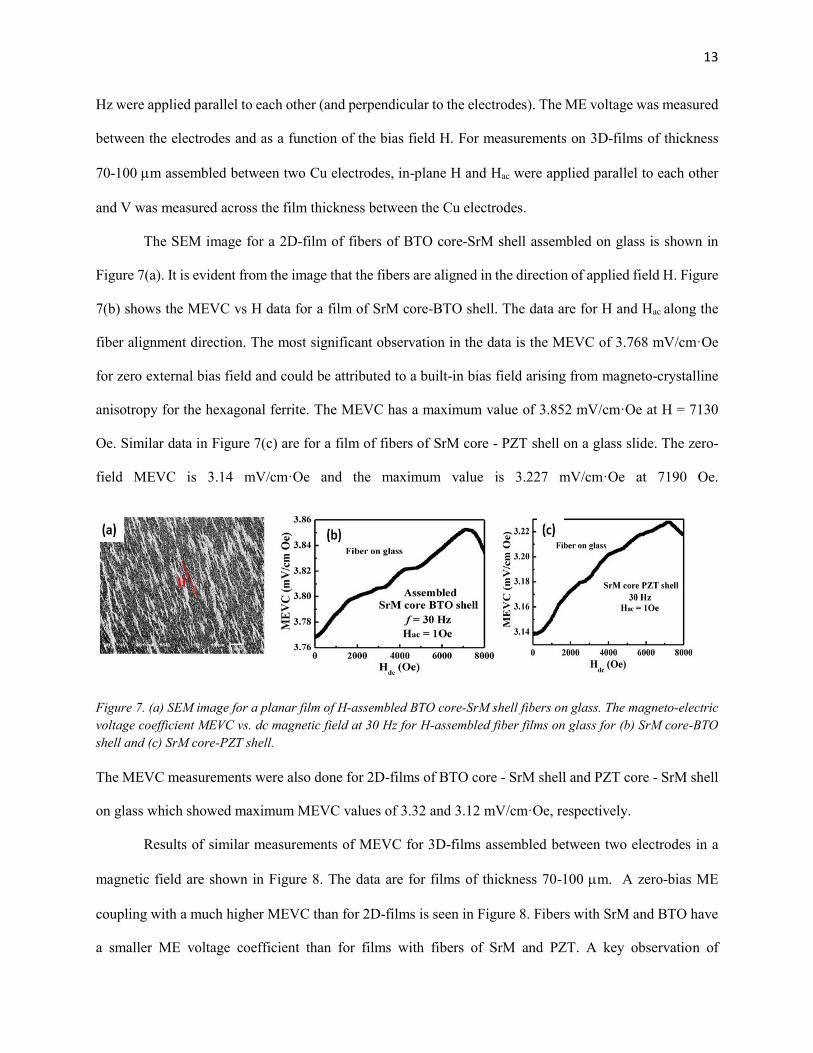
The SEM image for a 2D-film of fibers of BTO core-SrM shell assembled on glass is shown in
Figure 7(a). It is evident from the image that the fibers are aligned in the direction of applied field H. Figure
7(b) shows the MEVC vs H data for a film of SrM core-BTO shell. The data are for H and Hac along the
fiber alignment direction. The most significant observation in the data is the MEVC of 3.768 mV/cm·Oe
for zero external bias field and could be attributed to a built-in bias field arising from magneto-crystalline
anisotropy for the hexagonal ferrite. The MEVC has a maximum value of 3.852 mV/cm·Oe at H = 7130
Oe. Similar data in Figure 7(c) are for a film of fibers of SrM core - PZT shell on a glass slide. The zero-
field MEVC is 3.14 mV/cm·Oe and the maximum value is 3.227 mV/cm·Oe at 7190 Oe.
Figure 7. (a) SEM image for a planar film of H-assembled BTO core-SrM shell fibers on glass. The magneto-electric
voltage coefficient MEVC vs. dc magnetic field at 30 Hz for H-assembled fiber films on glass for (b) SrM core-BTO
shell and (c) SrM core-PZT shell.
The MEVC measurements were also done for 2D-films of BTO core - SrM shell and PZT core - SrM shell
on glass which showed maximum MEVC values of 3.32 and 3.12 mV/cm·Oe, respectively.
Results of similar measurements of MEVC for 3D-films assembled between two electrodes in a
magnetic field are shown in Figure 8. The data are for films of thickness 70-100 m. A zero-bias ME
coupling with a much higher MEVC than for 2D-films is seen in Figure 8. Fibers with SrM and BTO have
a smaller ME voltage coefficient than for films with fibers of SrM and PZT. A key observation of

14
importance in Figure 8 is the higher MEVC for films with ferroelectric shell than for films with ferrite shell.
Results in both Figures 7 and 8 show weak dependence of MEVC on H and could be attributed to a nearly
constant value of the piezomagnetic coefficient d/dH, where is the magnetostriction for SrM, for the
static field range H up to 8 kOe.
Figure 8. ME voltage coefficients versus H data as in Figure 7, but for 3D-films of core-shell fibers of (a) SrM-BTO
and (b) SrM-PZT.
4. Discussion
Although the primary focus of this work was on multiferroic core-shell fibers, it was essential to
study the nature of pure ferroic fibers for comparison of order parameters for both single phase and
composite fibers. Results of this study clearly demonstrate the feasibility of synthesizing ferroic and
multiferroic nanofibers by electrospinning. Fiber dimensions could be controlled with several parameters
including the sol viscosity and the strength of the electric field applied between the needle and the collector.
The profiles in Figures 1 and 2 for the distribution of fiber diameter indicate the potential for synthesizing
65% fibers with a deviation in diameter by ±13% and 85% of fibers with a deviation of ±17%. In the case
of ferroic fibers, X-ray diffraction data indicated the absence of impurity phases in annealed SrM and PZT
fibers. For pure BTO fibers, however, it was necessary to anneal the fibers at or above 900 ℃ in order to
eliminate the formation of non-ferroelectric cubic phase. We also inferred from our studies that heating and
cooling rates for annealing the fibers will have to be on the order of 0.25 to 0.5 ℃/min for obtaining fibers

15
free of voids and blow holes. Electron microscopy and scanning probe microscopy images for as-spun and
annealed fibers revealed defect free and uniform ferroic fibers.
The ferroic order parameters for pure SrM, BTO and PZT fibers is considered next. Past studies on
hexagonal ferrite fibers involved the use of blow spinning and annealing above 700 ℃ resulted in the
formation of single phase SrM fibers with room temperature Ms of 81.2 emu/g. [57,58] Fibers of SrM prepared
by electrospinning was reported to have a much smaller Ms of 64.5 emu/g. [59] In the present work eletrospun
fibers of single phase SrM with Ms ~ 72 emu/g were obtained for annealing temperature Ta above 900 ℃.
For the ferroelectric fibers P vs E data in Figure 3 show a much smaller Pr compared to thin film values for
BTO and PZT. [60,61] The ferroelectric order parameters for BTO fibers critically depend on the annealing
temperature Ta. Previous studies on BTO fibers reported the formation of tetragonal perovskite phase for
Ta above 700 ℃. [46] In another recent study on BTO fibers, conversion of non-ferroelectric cubic phase to
ferroelectric tetragonal was found occur for Ta > 950 ℃ and P vs E data for fibers for Ta ~1050 ℃ showed
Pr ~ 0.1 C/cm2. [47] We also observed a significant amount of cubic phase in BTO fibers for Ta = 700 ℃
whereas annealing at 900 ℃ resulted in tetragonal phase with a small amount of hexagonal phase. The P
vs E data in Figure 3(b) show Pr ~ 0.1 C/cm2 in agreement with the reported value in Ref.47. The reduction
in Pr compared to thin films was attributed to grain boundaries in the nanocrystals in the fibers that give
rise to clamping of domain walls and impede domain switching. [47] The data in Figure 3 shows a higher Pr
of 0.5 C/cm2 for PZT fibers and is comparable to Pr of 1.5 C/cm2 measured for E = 400 kV/cm for PZT
nanotube consisting of nanometer sized crystals. [62] Thus for both BTO and PZT fibers the saturation and
remnant polarizations are at least an order of magnitude smaller compared to thin film or bulk values.
The core-shell structure for fibers of SrM and the ferroelectrics were confirmed by electron and
scanning probe microscopy (Figure 4) and the annealed fibers were found to be free of impurity phases.
We also inferred from SMM images that the SrM core diameter was small compared to the ferroelectric
shell thickness. This is further confirmed by room temperature Ms = 2.5 – 4.5 emu/g for the annealed fibers
in Figure 5. Assuming average size of fiber diameter and shell thickness in the SMM images of Figure 4,

16
one obtains a ferrite-only Ms of 32 emu/g which is a factor of 2 smaller than for pure ferrite fibers. The
cause of this reduction in Ms for the core-shell fibers needs further investigation. A similar reduction in the
magnetization was also reported for core shell fibers of nickel ferrite (NFO) and PZT and NFO-BTO. [28, 29]
The remnant polarization values of 0.05 C/cm2 and 1 C/cm2 for the core-shell fibers of SrM with BTO
and PZT, respectively, are comparable to values in Figure 3 for pure ferroelectric fibers.
The strength of ME coupling measured by H induced ferroelectric polarization on discs of the fibers
are indicative of strong coupling in both SrM-BTO and SrM-PZT. The remnant polarization decreases in
both systems with the application of H and the fractional change in Pr is higher in SrM-PZT than for SrM-
BTO and could be due to higher polarization for fibers with PZT. Another observation of importance is the
larger change in Pr measured for fibers with ferroelectric shell than for SrM shell and could be attributed to
a higher leakage current expected for fibers with low resistivity ferrite than for fibers with ferroelectric
shell. In our earlier studies on discs of randomly oriented fibers of NFO and PZT or BTO, we observed a
fractional increase in Pr by 6% for H = 7 kOe whereas in the present system with hexagonal ferrites the
change in Pr is a factor of 2 to 3 higher than in the spinel ferrite-ferroelectric fibers. [28,29] The H-induced
polarization in bulk ferrite-ferroelectric composites and in single phase multiferroics show a much smaller
change in Pr compared to the present system. [63,64]
The ME voltage coefficient data in Figure 7 for 2D-films assembled in a magnetic field is on the
order of 3.1 to 3.9 mV/cm Oe with a large ME response for H = 0. Such zero-bias ME effects could be due
a self-biasing field arising from grading of ferroic order parameters or a remnant magnetization due to
magnetocrystalline anisotropy. [65,66] The zero-bias MEVC in the data of Figure 7 is due to the uniaxial
anisotropy field for M-type hexagonal ferrites that would give rise to a large remnant magnetization that
acts as a built-in internal bias field. Another key observation in the data is the weak H dependence of MEVC
for fields up to 8 kOe. The ME voltage coefficient is directly proportional to the piezomagnetic coefficient
q = d/dH where is the magnetostriction. Thus the MEVC vs H tracks the dependence of q on H and in
the case of composites with spinel ferrites or soft magnetic materials MEVC drops to zero when attains

17
saturation and q ~ 0 at high bias fields. In the present case, however, it is clear that q remains almost constant
for H up to 8 kOe. The ME voltage coefficients in Figure 7 is an order of magnitude higher than for H-
assembled 2D films of NFO-PZT and NFO-BTO. [28,29]
The MEVC data in Figure 8 for 3D films show a significant enhancement in the magnitude of
MEVC compared to 2D films. The results are for in-plane parallel H and Hac and ME voltage measured
across the film thickness. A higher MEVC for samples with PZT than for films with BTO is likely due to
superior ferroelectric order parameter for PZT that is evident in the P vs E data in Figure 5. Another
observation, in agreement with the H-induced polarization, is the higher MEVC for samples with
ferroelectric shell than for ferrite shell due to a smaller leakage current for the films with high resistivity
ferroelectric shells. The ME response in Figures 7 and 8, however, is weak compared to measured MEVC
values for layered composites of PZT and single crystal SrM. [67] For the fiber films the strength of ME
coupling is weakened due to several factors including electric and magnetic dipole-dipole interactions
between fibers and film porosity. Although demagnetization effects will vanish for bias magnetic field and
ac field along the fiber axis, the dipole-dipole coupling between magnetic cores or shells, fiber discontinuity
in an assembled structure, porosity and voids in the films, in particular in the 2D films, will also contribute
to weakening of sample magnetization and magnetostriction and lowering of ME voltages. Similarly,
piezoelectric coefficient will be weakened due to electric dipole interaction between PZT or BTO cores or
shells. Thus the ME voltage coefficient in 2D and 3D films will also be weaker compared to a free standing
single nanofiber.
It is essential to carry out measurements of ME coupling in on single isolated fibers. Quantitative
measurements of direct and converse-ME coupling could be done on stand-alone composite fibers placed
on templates by nano-manipulation. Some of the suggested measurements in this regard include scanning
probe microscopy techniques such as piezo-force microscopy under H, magnetic force microscopy under
an applied voltage, ferromagnetic resonance under an electric field with an SMM, and MEVC
measurements with nanoprobes.

18
Multiferroic core-shell fibers investigated here do show the potential to achieve strong ME coupling. Focused
efforts that address the following are essential in order to realize coupling strengths predicted by theory. [22] (i) Ferroic
order parameters for cores and shells are measured to be much smaller than values for bulk materials and thin films.
The fibers contain nanocrystallites and one has to understand the influence of their size and shape on the order
parameters. (ii) Fibers with ferrite cores were found to have a much smaller diameter compared to ferroelectric shell
thickness. Since the ME coupling is maximum for equal volume of the two ferroic phases, electrospinning synthesis
parameters that control the core and shell dimensions need to be explored. (iii) Annealing temperatures for the fibers
and heating and cooling rates are found to be key parameters that determine the crystallographic phases, size of
nanocrystallites and pores and voids in the fibers. Undesired phased such as cubic BTO need to be eliminated for
strong ME coupling. It is desirable to study the correlation between the fiber annealing parameters to ferroic order
parameters. (iv) Fiber discs and 2D and 3D films used for ME measurements discussed in this study are susceptible
to a large leakage current generally encountered in bulk composites and will lead to a significant reduction in the
strength of ME coupling. Previously suggested ME measurements on isolated single fibers need to performed for
understanding the nature of ME interactions in the composites. (v) Finally, the study has to be expanded to include Y-
and W-type hexaferrites since one may realize a much higher magnetostriction and ME coupling strength than for
composites with M-type ferrites. Composites with fibers of Y-type ferrites (Ba2Me2Fe12O22, Me = Ni, Zn) that
have uniaxial anisotropy; or W-type ferrites Ba Me2 Fe16 O27 (Me = Co, Zn) with uniaxial or planar
anisotropy are potential candidate materials for follow up studies.
There has been considerable interest in recent years in composite multiferroics. This report therefore
addresses a new family of multiferroic nanomaterials with potential for achieving strong ME coupling. It
is necessary to explore the paths for synthesizing nanofibers with order parameters comparable to bulk
materials. It is also necessary to come up with a viable path for instantaneous assembly of the nanofibers
into superstructures. Measurements of ME coupling in nano-fibers and comparison measurements on
assemblies will lead to a basic understanding of the nature of electromagnetic interactions and applications
in sensor and signal processing technologies. In addition, local measurement for the individual fibers may
help unambiguously reveal the physical origin of these various coupling effects. We anticipate new

19
phenomena, theory, and novel applications to emerge from this research. We summarize the details of the
3-year program in Table 2 below.
5. Conclusions
Nanofibers of M-type Sr-hexaferrite and ferroelectric PZT and BTO and coaxial ferrite-
ferroelectric fibers have been synthesized by electrospinning. Pure ferrite and ferroelectric fibers were of
uniform diameter that could be controlled with sol viscosity and electric field applied during electrospinning.
Electron and scanning probe microscopy images revealed fibers of uniform diameter. Annealed fibers were
characterized in terms of order parameters. The saturation magnetization for SrM fiber agreed with the
values expected for bulk ferrites. The polarization values for PZT and BTO fibers agreed with past reports
for fibers, but were smaller than the bulk values. Images obtained by scanning microwave microscopy
showed core-shell structures for the composite nanowires with the diameter in the range 220 ~ 1000 nm.
The multiferroic coaxial fibers, however, showed a smaller saturation magnetization or remnant
polarization compared to values for pure ferroic fibers. The strength of magnetoelectric interactions were
measured by magnetic field induced polarization and ME voltage coefficient. The remnant polarization
decreased with the application of H in all of the fiber samples, with a decrease as high as 20% for SrM-PZT
fibers. The MEVC was measured for both 3D and 2D fiber films assembled in a magnetic field. Both types
of films had a large zero-bias ME response and the 3D films showed a higher MEVC of 14 - 22 mV/cm·Oe
than 3.2 – 3.8 mV/cm·Oe for 2D films. The ME interaction strengths for coaxial fibers studied here are
smaller than predicted by theory. Follow up studies on control of fibers parameters aimed at improving the
ferroic order parameters are essential. Efforts also must focus on obtaining fibers with equal volume
fraction of ferromagnetic and ferroelectric phase to enhance the ME coupling strengths. It is also necessary
to study the correlation between fiber diameter, size of nano-crystallites in the fibers, ferroic order
parameters and ME coupling. Finally, the nature of magneto-electric effects in single fiber must be

20
performed for better understanding of the ME coupling in these nanostructures and to explore potential
applications in sensors and advanced technologies.
Acknowledgements
The research at Oakland University was supported by grants from the National Science
Foundation (DMR-1808892, ECCS-1923732). Ying Liu was supported by a fellowship from the
Chinese Scholarship Council. The research at AFRL was partially supported by the Air Force
Office of Scientific Research (AFOSR) Award No. FA9550-20RXCOR074, and a Summer
Faculty Fellowship for G.S. Efforts at the Argonne National Laboratory were supported by a grant
from the DOE-BSE-Materials Science and Engineering Division.

21
Caption for Figures
Figure 1. (a) SEM image for as-spun SrM fibers. (b) Number of fibers versus diameter profile for fibers
annealed at 900 ℃. (c) XRD data for SrM fibers annealed at 900 ℃ and 1000℃. (d) Room temperature
magnetization M vs. H for SrM fibers annealed at 800 ℃, 900 ℃, and 1000 ℃.
Figure 2. (a) SEM image for as-synthesized PZT fibers. (b) Number of fibers versus diameter for BTO
fibers annealed at 900 ℃. XRD data for (c) PZT fibers annealed at 800 ℃ and 900 ℃ and (d) BTO fibers
annealed at 700 ℃ and 850 ℃.
Figure 3. Polarization vs. E for disks of (a) PZT fibers and (b) BTO fiber annealed at 900 ℃.
Figure 4. (a) SEM image for a fiber with SrM core-BTO shell annealed at 700 ℃. (b) XRD data for PZT
core-SrM shell and BTO core-SrM shell fibers annealed at 900 ℃. Scanning microwave microscopy
(SMM) images of topography [(c) and (g)], capacitance [(d) and (h)], S11 amplitude [(e) and (i)] and S11
phase [(f) and (j)] for annealed fibers of SrM core-BTO shell and SrM core-PZT shell, respectively.
Figure 5. Room temperature magnetization M vs. H for (a) SrM -BTO and (b) SrM-BTO fibers annealed
at 900 ℃. Ferroelectric polarization P vs. E for (c) SrM-BTO and (d) SrM-PZT fibers at various frequencies.
Figure 6. (a) Polarization P vs. E under H and (b) the estimated fractional change in Pr with H for a disc of
fibers of (a) PZT core-SrM shell. (c) and (d) show similar data for a disc of fibers of SrM core-BTO shell.
Figure 7. (a) SEM image for a planar film of H-assembled BTO core-SrM shell fibers on glass. The
magneto-electric voltage coefficient MEVC vs. dc magnetic field at 30 Hz for H-assembled fiber films on
glass for (b) SrM core-BTO shell and (c) SrM core-PZT shell.
Figure 8. ME voltage coefficients versus H data as in Figure 7, but for 3D-films of core-shell fibers of (a)
SrM-BTO and (b) SrM-PZT.

22
References
1. C. Nan: Magnetoelectric effect in composites of piezoelectric and piezomagnetic phases. Phys. Rev. B
50, 9 (1994).
2. J. Ryu, S. Priya, K. Uchino, and H.E. Kim: Magnetoelectric effect in composites of magnetostrictive and
piezoelectric materials. J. Elec. 8, 2 (2002).
3. W. Eerenstein, N.D. Mathur, and J.F. Scott: Multiferroic and magnetoelectric materials. Nature 442,
7104 (2006).
4. R. Ramesh and N.A. Spaldin: Multiferroics: progress and prospects in thin films. Nat. Mater. 6, 21 (2007).
5. C. Nan, M.I. Bichurin, S. Dong, D. Viehland, and G. Srinivasan: Multiferroic magnetoelectric composites:
Historical perspective, status, and future directions. J. Appl. Phys. 103, 3 (2008).
6. J. Zhai, Z. Xing, S. Dong, J. Li, and D. Viehland: Magnetoelectric laminate composites: an overview. J.
Am. Ceram. Soc. 91, 2 (2008).
7. S. Priya, R. Islam, S. Dong, and D. Viehland: Recent advancements in magnetoelectric particulate and
laminate composites. J. Elec. 19, 1 (2007).
8. G. Srinivasan: Magnetoelectric composites. Annu. Rev. Mater. Res. 40, 153-178 (2010).
9. J. Cui, J.L. Hockel, P K. Nordeen, D.M. Pisani, C. Liang, G.P. Carman, and C.S. Lyncha: A method to
control magnetism in individual strain-mediated magnetoelectric islands. Appl. Phys. Lett. 103, 23
(2013).
10. G. Srinivasan, S. Priya, and N.X. Sun: Composite magnetoelectrics: materials, structures, and
applications. Elsevier (2015).
11. V. Corral-Flores, D. Bueno-Baques, D. Carrillo-Flores, and J.A. Matutes-Aquino: Enhanced
magnetoelectric effect in core-shell particulate composites. J. Appl. Phys. 99, 8 (2006).
12. R.S. Devan, and B.K. Chougule: Effect of composition on coupled electric, magnetic, and dielectric
properties of two phase particulate magnetoelectric composite. J. Appl. Phys. 101, 1 (2007).
13. H. Yang, G. Zhang, Y. Lin, T. Ye, and P. Kang: Electrical, magnetic and magnetoelectric properties of
BaTiO3/BiY2Fe5O12 particulate composites. Ceram. Int. 41, 5 (2015).
14. Y. Benveniste: Magnetoelectric effect in fibrous composites with piezoelectric and piezomagnetic
phases. Phys. Rev. B 51, 22 (1995).
15. L.P. Liu, and H.Y. Kuo: Closed-form solutions to the effective properties of fibrous magnetoelectric
composites and their applications. Int. J. Solids Struct. 49, 22 (2012).
16. H.Y. Kuo, and Y.L. Wang: Optimization of magnetoelectricity in multiferroic fibrous composites. Mech.
Mater. 50, 88-99 (2012).

23
17. J. Hu, Z. Li, J. Wang, and C.W. Nan: Electric-field control of strain-mediated magnetoelectric random
access memory. J. Appl. Phys. 107, 9 (2010).
18. N.X. Sun, and G. Srinivasan: Voltage control of magnetism in multiferroic heterostructures and devices.
Spin, World Scientific Publishing Company 2, 1240004 (2012).
19. M.M. Vopson: Fundamentals of multiferroic materials and their possible applications. Crit. Rev. Solid
State Mater. Sci. 40, 223-250 (2015).
20. C.M. Leung, J.F. Li, D. Viehland, and X. Zhuang: A review on applications of magnetoelectric
composites: from heterostructural uncooled magnetic sensors, energy harvesters to highly efficient
power converters. J. Phys. D: Appl. Phys. 51, 263002 (2018).
21. D. Viehland, M. Wuttig, J. McCord, and E. Quandt: Magnetoelectric magnetic field sensors. MRS Bull.
43, 834-840 (2018).
22. V.M. Petrov, J. Zhang, H. Qu, P. Zhou, T. Zhang, and G. Srinivasan: Theory of magnetoelectric effects
in multiferroic core-shell nanofibers of hexagonal ferrites and ferroelectrics. J. Phys. D: Appl. Phys. 51,
28 (2018).
23. C. Vaz, J. Hoffman, C.H. Ahn, and R. Ramesh: Magnetoelectric coupling effects in multiferroic
complex oxide composite structures. Adv. Mater. 22, 2900-2918 (2010).
24. D. Viehland, J.F. Li, Y. Yang, T. Costanzo, A. Yourdkhani, G. Caruntu, P. Zhou, T. Zhang, T. Li, A.
Gupta, M. Popov, and G. Srinivasan: Tutorial: Product properties in multiferroic nanocomposites. J.
Appl. Phys. 124, 061101 (2018).
25. X.Z. Chen, M. Hoop, N. Shamsudhin, T. Huang, B. Özkale, Q. Li, E. Siringil, F. Mushtaq, L. Di Tizio,
B.J. Nelson, and S. Pané: Hybrid magnetoelectric nanowires for nanorobotic applications: fabrication,
magnetoelectric coupling, and magnetically assisted in vitro targeted drug delivery. Adv. Mater. 29, 8
(2017).
26. S. Xie, F. Ma, Y. Liu, and J. Li: Multiferroic CoFe2O4-Pb(Zr0.52Ti0.48)O3 core-shell nanofibers and their
magnetoelectric coupling. Nanoscale 3, 8 (2011).
27. Q. Zhu, Y. Xie, J. Zhang, Y. Liu, Q. Zhan, H. Miao, and S. Xie: Multiferroic CoFe2O4-BiFeO3 core-
shell nanofibers and their nanoscale magnetoelectric coupling. J. Mater. Res. 29, 5 (2014).
28. G. Sreenivasulu, M. Popov, R. Zhang, K. Sharma, C. Janes, A. Mukundan, and G. Srinivasan: Magnetic
field assisted self-assembly of ferrite-ferroelectric core-shell nanofibers and studies on magneto-electric
interactions. Appl. Phys. Lett. 104, 5 (2014).
29. G. Sreenivasulu, J. Zhang, R. Zhang, M. Popov, V. Petrov, and G. Srinivasan: Multiferroic core-shell
nanofibers, assembly in a magnetic field, and studies on magneto-electric interactions. Materials 11, 1
(2018).

24
30. G. Caruntu, A. Yourdkhani, M. Vopsaroiu, and G. Srinivasan: Probing the local strain-mediated
magnetoelectric coupling in multiferroic nanocomposites by magnetic field-assisted piezoresponse force
microscopy. Nanoscale 4, 3218-3227 (2012).
31. Y. Liu, J. Zhang, P. Zhou, C. Dong, X. Liang, W. Zhang, T. Zhang, N.X. Sun, D. Filippov, and G.
Srinivasan: Magneto-electric interactions in composites of self-biased Y-and W-type hexagonal ferrites
and lead zirconate titanate: Experiment and theory. J. Appl. Phys. 126, 114102 (2019).
32. J.H. Li, I. Levin, J. Slutsker, V. Provenzano, P. K. Schenck, R. Ramesh, J. Ouyang, and A.L. Roytburd:
Self-assembled multiferroic nanostructures in the CoFe2O4-PbTiO3 system. Appl. Phys. Lett. 87, 072909
(2005).
33. H. Zheng, J. Wang, S.E. Lofland, Z. Ma, L. Mohaddes-Ardabili, T. Zhao, L. Salamanca-Riba, S.R.
Shinde, S.B. Ogale, F. Bai, D. Viehland, Y. Jia, D.G. Schlom, M. Wuttig, A. Roytburd, and R. Ramesh:
Multiferroic BaTiO3-CoFe2O4 nanostructures. Science 303, 661-663 (2004).
34. X.S. Gao, B.J. Rodriguez, L. Liu, B. Birajdar, D. Pantel, M. Ziese, M. Alexe, and D. Hesse:
Microstructure and properties of well-ordered multiferroic Pb(Zr,Ti)O3/CoFe2O4 nanocomposites. ACS
Nano 4, 1099 (2010).
35. I. Vrejoiu, A. Morelli, D. Biggemann, and E. Pippel: Ordered arrays of multiferroic epitaxial
nanostructures. Nano Rev. 2, 7364 (2011).
36. Y. Yang, S. Priya, J. Li, and D. Viehland: Two-phase coexistence in single-grain BaTiO3-
(Mn0.5Zn0.5)Fe2O4 composites, via solid-state reaction. J. Am. Ceram. Soc. 92, 1552 (2009).
37. F. Bai, H. Zhang, J. Li, and D. Viehland: Magnetic and magnetoelectric properties of as-deposited and
annealed BaTiO3-CoFe2O4 nanocomposite thin films. J. Phys.D: Appl. Phys. 43, 285002 (2010).
38. L. Li, Lu Lu, Dawei Zhang, Ran Su, Guang Yang, Junyi Zhai, and Yaodong Yang: Direct Observation
of Magnetic Field Induced Ferroelectric Domain Evolution in Self-Assembled Quasi (0-3) BiFeO3–
CoFe2O4 Thin Films. ACS Appl. Mater. Interfaces 8, 442 (2015).
39. G. Caruntu, A. Ypurdkhani, M. Vopsaroiu, and G. Srinivasan: Probing the local strain-mediated
magnetoelectric coupling in Multiferroic nanocomposites by magnetic field-assisted piezoresponse
microscopy. Nanoscale 4, 3218 (2012).
40. Z.H. Hua, P. Yang, H.B. Huang, J.G. Wan, Z.Z. Yu, S.G. Yang, M. Lu, B.X. Gu, and Y.W. Du: Sol-
gel template synthesis and characterization of magnetoelectric CoFe2O4/Pb(Zr0.52Ti0.48)O3 nanotubes.
Mater.Chem. Phys. 107, 541-546 (2008).
41. M. Liu, X. Li, H. Imrane, Y.J. Chen, T. Goodrich, Z.H. Cai, K.S. Ziemer, J.Y. Huang, and N.X. Sun:
Synthesis of ordered arrays of multiferroic NiFe2O4-Pb(Zr0.52Ti0.48)O3 core-shell nanowires. Appl. Phys.
Lett. 90, 152501 (2007).
42. R.C. Pullar: Hexagonal ferrite fibres and nanofibres. Solid State Phenom. 241, 1-68 (2016).

25
43. R.C. Pullar: Hexagonal ferrites: a review of the synthesis, properties and applications of hexaferrite
ceramics. Prog. Mater. Sci. 57, 1191-1334 (2012).
44. R.C. Pullar, M.D. Taylor, and A.K. Bhattacharya: A halide free route to the manufacture of
microstructurally improved M ferrite (BaFe12O19 and SrFe12O19) fibres. J. Eur. Ceram. Soc. 22, 12
(2002).
45. R. Sun, X. Li, A. Xia, S. Su, and C. Jin: Hexagonal SrFe12O19 ferrite with high saturation magnetization.
Ceram. Int. 44, 12 (2018).
46. J. Yuh, J.C. Nino, and W.M. Sigmund: Synthesis of barium titanate (BaTiO3) nanofibers via
electrospinning. Mater. Lett. 59, 28 (2005).
47. Y. Wei, Y. Song, X. Deng, B. Han, X. Zhang, Y. Shen, and Y. Lin: Dielectric and ferroelectric
properties of BaTiO3 nanofibers prepared via electrospinning. J. Mater. Sci. Tech. 30, 8 (2014).
48. Z. Miao, L. Chen, F. Zhou, and Q. Wang: Modulation of resistive switching characteristics for
individual BaTiO3 microfiber by surface oxygen vacancies. J. Phys. D: Appl. Phys. 51, 2 (2017).
49. H. Tang, Z. Zhou, and H.A. Sodano: Relationship between BaTiO3 nanowire aspect ratio and the
dielectric permittivity of nanocomposites. ACS Appl. Mater. Interfaces 6, 5450-5455 (2014).
50. K.J. Choi, M. Biegalski, Y.L. Li, A. Sharan, J. Schubert, R. Uecker, P. Reiche Y.B. Chen, X.Q. Pan, V.
Gopalan, L.Q. Chen, D.G. Schlom, C.B. Eom: Enhancement of ferroelectricity in strained BaTiO3 thin
films. Science 306, 1005-1009 (2004).
51. Zhao Wang, Xumin Pan, Yahua He, Yongming Hu, Haoshuang Gu, and Yu Wang: Piezoelectric
nanowires in energy harvesting applications. Adv. Mater. Sci. Eng. 2015, 165631 (2015).
52. X. Chen, S. Xu, N. Yao, W. Xu, and Y. Shi: Potential measurement from a single lead ziroconate
titanate nanofiber using a nanomanipulator. Appl. Phys. Let. 94, 253113 (2009).
53. K.H. Cho, and S. Priya: Synthesis of ferroelectric PZT fibers using sol–gel technique. Mater. Lett. 65,
4 (2011).
54. H.N. Lee, S.M. Nakhmanson, M.F. Chisholm, H.M. Christen, K.M. Rabe, and D. Vanderbilt:
Suppressed dependence of polarization on epitaxial strain in highly polar ferroelectrics. Phys. Rev. Lett.
98, 21 (2007).
55. M. Fan, W. Hui, Z. Li, Z. Shen, H. Li, A. Jiang, and Y. Chen: Fabrication and piezoresponse of
electrospun ultra-fine Pb(Zr0.3,Ti0.7)O3 nanofibers. Microelectronic Eng. 98, 371 (1998).
56. M. H. Malakooti, Zhi Zhou, and Henry A. Sodano: Enhanced energy harvesting through nanowire
based functionally graded interfaces. Nano Energy 52, 171-182 (2018).
57. R.C. Pullar, M.D. Taylor, and A.K. Bhattacharya: Halide removal from BaM (BaFe12O19) and SrM
(SrFe12O19) ferrite fibers via a steaming process. J. Mater. Res. 16, 3162-3169 (2001).

26
58. R.C. Pullar, I.K. Bdikin, and A.K. Bhattacharya: Magnetic properties of randomly oriented BaM, SrM,
Co2Y, Co2Z and Co2W hexagonal ferrite fibres. J. Eur. Ceram. Soc. 32, 905-913 (2012).
59. M.Q. Liu, X.Q. Shen, X.F. Meng, F.Z. Song, and J. Xiang: Fabrication and magnetic property of M-
type strontium ferrite nanofibers by electrospinning. J. Inorg. Mater. 1 (2010).
60. P. Muralt, M. Kohli, T. Maeder, A. Kholkin, K. Brooks, N. Setter, and R. Luthier: Fabrication and
characterization of PZT thin-film vibrators for micromotors. Sens. Actuators A: Phys. 48, 157-165
(1995).
61. K. Kajiyoshi, N. Ishizawa, and M. Yoshimura: Preparation of tetragonal barium titanate thin film on
titanium metal substrate by hydrothermal method. J. Am. Ceram. Soc. 74, 369-374 (1991).
62. J. Kim, S.A. Yang, Y.C. Choi, J.K. Han, K.O. Jeong, Y.J. Yun, D.J. Kim, S.M. Yang, D. Yoon, H.
Cheong, K.S. Chang, T.W. Noh, S.D. Bu: Ferroelectricity in highly ordered arrays of ultra-thin-walled
Pb(Zr,Ti)O3 nanotubes composed of nanometer-sized perovskite crystallites. Nano lett. 8, 1813-1818
(2008).
63. S. Liu, S. Yan, H. Luo, S. Huang, C. Liao, and L. Deng: Magnetic effects on polarization response in
particulate magnetoelectric Bi0.5Na0.5TiO3-La0.67Sr0.33MnO3 composites. Mater. Lett. 212, 139 (2018).
64. G. Lawes and G. Srinivasan: Introduction to magnetoelectric coupling and multiferroic films. J. Phys.
D: Appl. Phys. 44, 243001 (2011).
65. S.C. Yang, C.S. Park, K.H. Cho, and S. Priya: Self-biased magnetoelectric response in three-phase
laminates. J. Appl. Phys. 108, 093706 (2010).
66. Y. Zhou, D. Maurya, Y. Yan, G. Srinivasan, E. Quandt, and S. Priya: Self-biased magnetoelectric
composites: An overview and future perspectives. Energy Harvesting Syst. 3, 42 (2016).
67. V. L. Mathe, G. Srinivasan, and A. M. Balbashov: Magnetoelectric effects in bilayers of lead zirconate
titanate and single crystal hexaferrites. Appl. Phys. Lett. 92, 122505 (2008).