Embed Size (px)
Citation preview
1
Magnetic Resonance
Elastography (MRE)
By Farukh Saeed. Candidate
Graduate School of Biomedical Engineering,
McMaster University
Supervisor: Dr. Gerald Moran
2
Outline
• Elasticity.
• Magnetic Resonance elastography (MRE).
• Vibration Actuator.
• Modification of Gradient-recalled echoes (GRE) Sequence.
• Reconstruction Software.
• Agar Gel Phantom.
• Equipment and Experimental setup.
• Results.
• Conclusion Challenges and Future Plans.
3
Elasticity
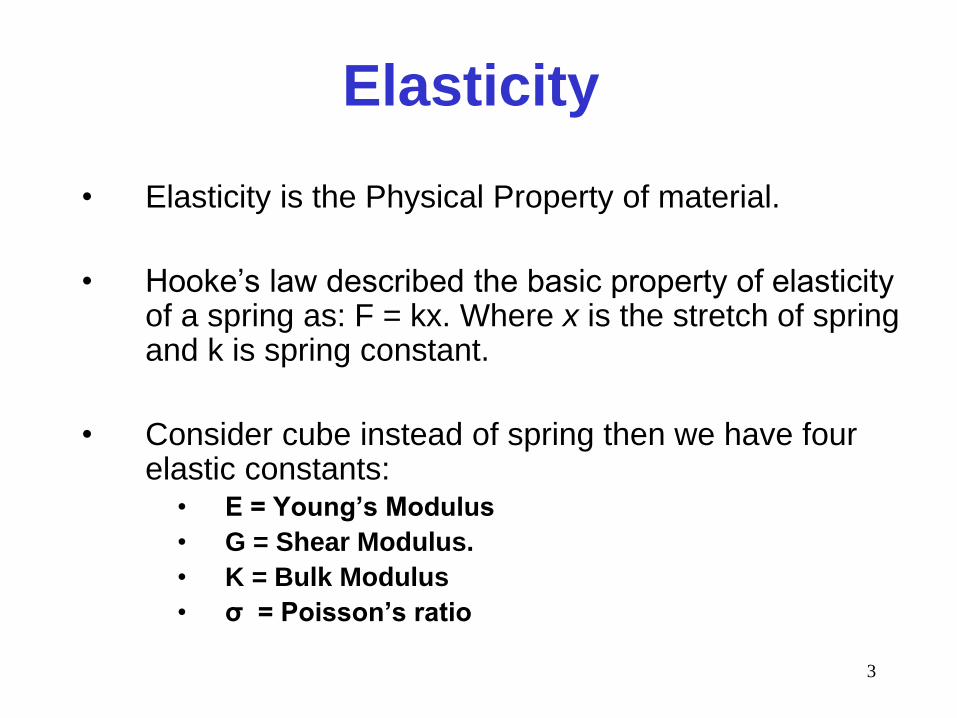
• Elasticity is the Physical Property of material.
• Hooke’s law described the basic property of elasticity of a spring as: F = kx. Where x is the stretch of spring and k is spring constant.
• Consider cube instead of spring then we have four elastic constants:
• E = Young’s Modulus
• G = Shear Modulus.
• K = Bulk Modulus
• σ = Poisson’s ratio
4
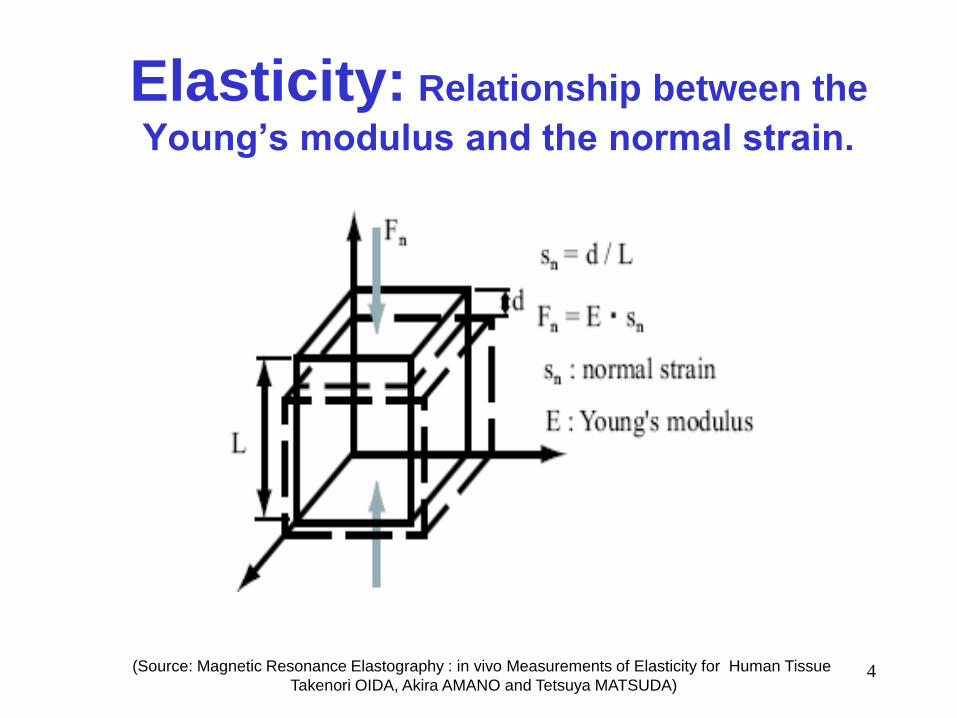
Elasticity: Relationship between the
Young’s modulus and the normal strain.
(Source: Magnetic Resonance Elastography : in vivo Measurements of Elasticity for Human Tissue
Takenori OIDA, Akira AMANO and Tetsuya MATSUDA)
5
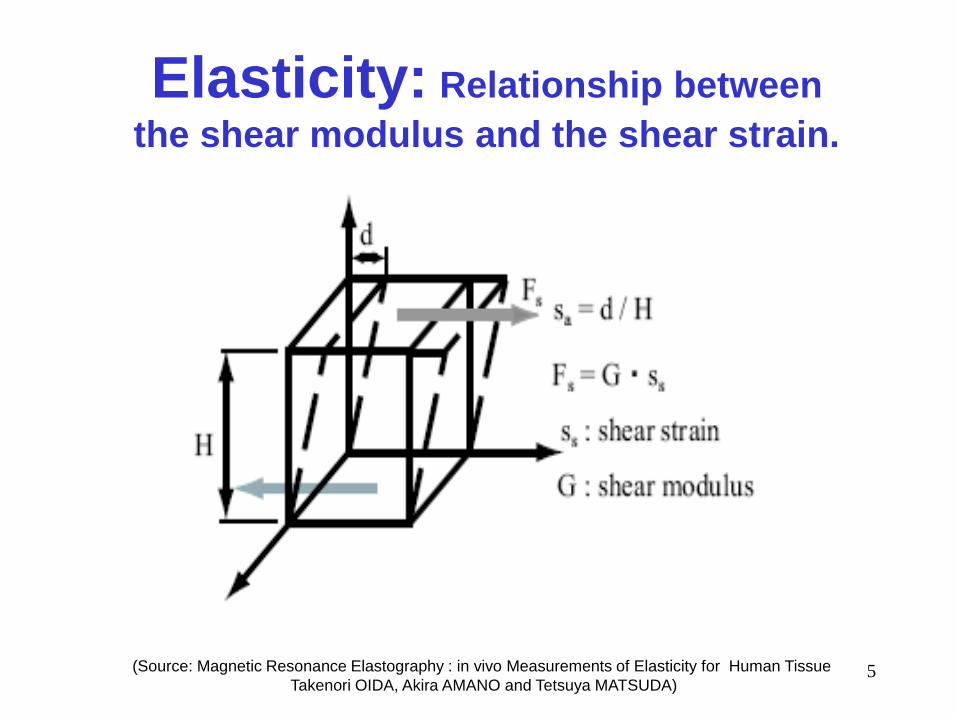
Elasticity: Relationship between
the shear modulus and the shear strain.
(Source: Magnetic Resonance Elastography : in vivo Measurements of Elasticity for Human Tissue
Takenori OIDA, Akira AMANO and Tetsuya MATSUDA)
6
Elasticity: Bulk modulus K and the
Poisson’s ratio σ
EG
EGK
39
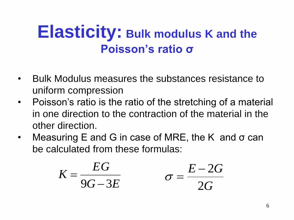
• Bulk Modulus measures the substances resistance to
uniform compression
• Poisson’s ratio is the ratio of the stretching of a material
in one direction to the contraction of the material in the
other direction.
• Measuring E and G in case of MRE, the K and σ can
be calculated from these formulas:
G
GE
2
2
7
Magnetic Resonance Elastography
• Physicians routinely use palpation to detect the elastic properties of tissues.
• Differences in elasticity can help facilitate the diagnosis of tumors.
• Difficult to obtain such properties in vivo by using conventional methods.
• MRE has been developed that provides noninvasive in vivo measurement of elasticity for Human tissue.
8
MRE: Method
• MRE is a method which calculates Elastic
modulus by measuring the waves caused by
oscillating the material externally.
• Wavelength of the propagating waves can be
easily acquired from MRI phase Images.
• In hard material waves travel fast and have longer
wavelength compare to soft materials where
waves travel slow and have shorter wavelength.
9
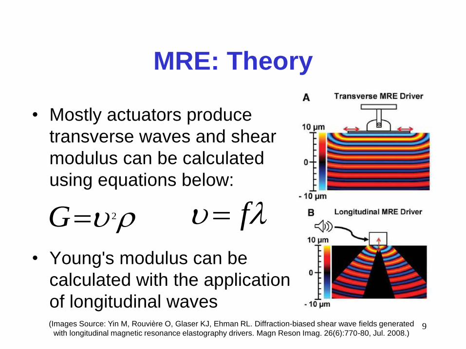
MRE: Theory
• Mostly actuators produce
transverse waves and shear
modulus can be calculated
using equations below:
• Young's modulus can be
calculated with the application
of longitudinal waves
2G f
(Images Source: Yin M, Rouvière O, Glaser KJ, Ehman RL. Diffraction-biased shear wave fields generated
with longitudinal magnetic resonance elastography drivers. Magn Reson Imag. 26(6):770-80, Jul. 2008.)
10
MRE: Required components
• Hardware device to oscillate the scanned region at known frequency called actuator.
• MRI Pulse sequence with motion encoding gradients to encode motion.
• Software to estimate the Wavelength from the acquired Phase images and reconstruct elasticity map.
11
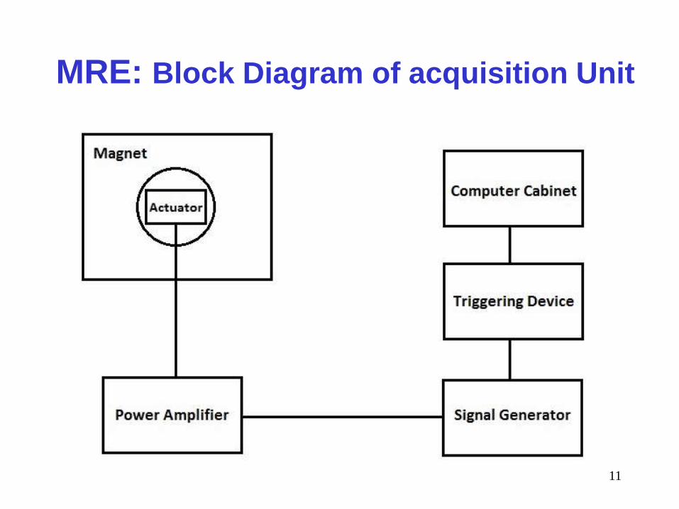
MRE: Block Diagram of acquisition Unit
12
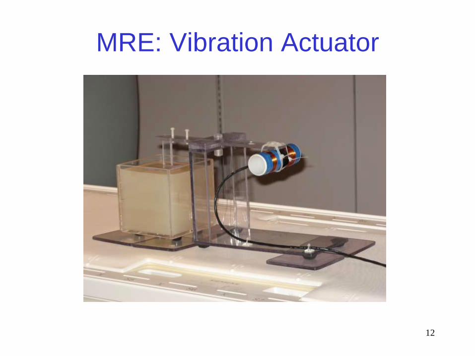
MRE: Vibration Actuator
13
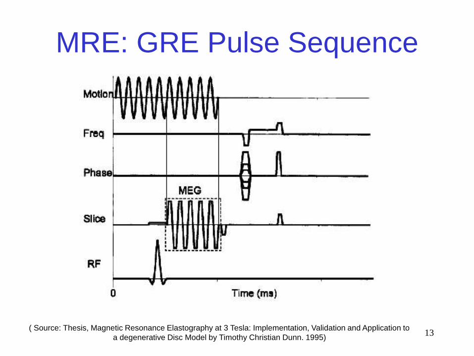
MRE: GRE Pulse Sequence
( Source: Thesis, Magnetic Resonance Elastography at 3 Tesla: Implementation, Validation and Application to
a degenerative Disc Model by Timothy Christian Dunn. 1995)
14
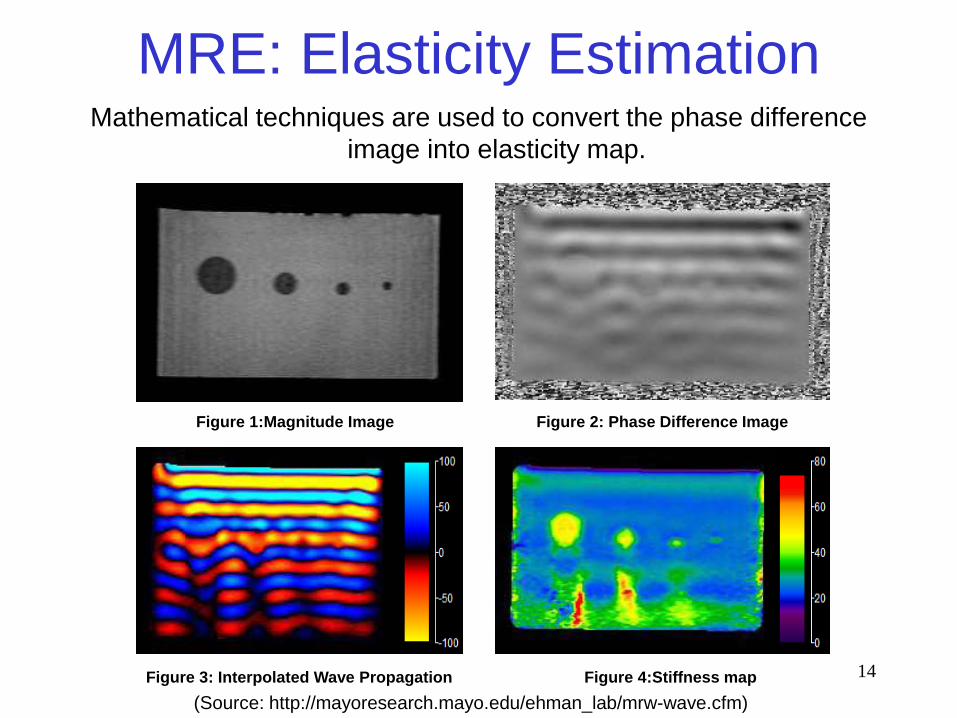
MRE: Elasticity EstimationMathematical techniques are used to convert the phase difference
image into elasticity map.
Figure 1:Magnitude Image Figure 2: Phase Difference Image
Figure 3: Interpolated Wave Propagation Figure 4:Stiffness map
(Source: http://mayoresearch.mayo.edu/ehman_lab/mrw-wave.cfm)
15
MRE: Clinical Applications
• Abdomen: Liver fibrosis.
• Brain: Alzheimer’s disease.
• Breast: Cancer.
• Cardiac: Shear modulus variations in
the LV Wall.
• Muscles: Healthy and pathological.
• Prostate: elastic properties.
16
MRE Study
• Design and construction of vibration actuator.
• Modification of GRE sequence.
• Selection of the reconstruction software.
17
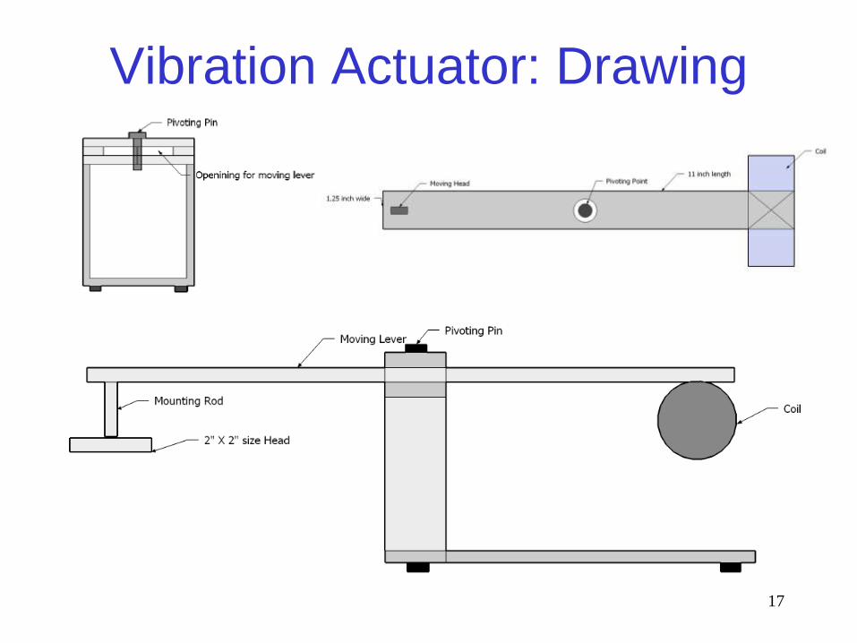
Vibration Actuator: Drawing
18
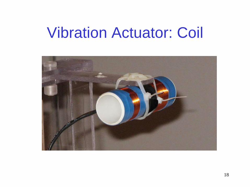
Vibration Actuator: Coil
19
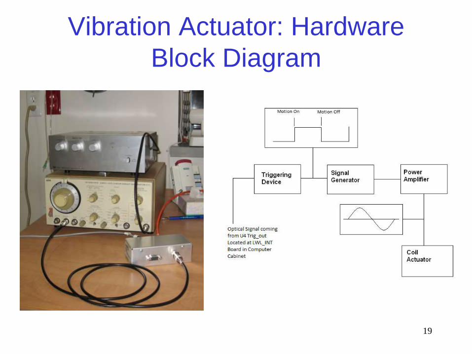
Vibration Actuator: Hardware
Block Diagram
20
Modified GRE Sequence
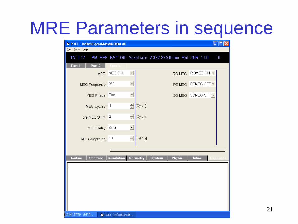
• Siemens GRE sequence is modified using
Siemens Integrated Development
Environment for Applications (IDEA).
• Create parameters in the sequence special
card related to MRE.
• Programmed bipolar motion encoding
gradients (MEGs) in the sequence. MEGs
can be applied in any one of the three axis.
21
MRE Parameters in sequence
22
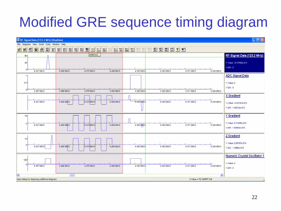
Modified GRE sequence timing diagram
23
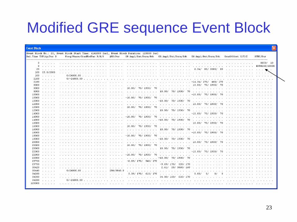
Modified GRE sequence Event Block
24
Reconstruction Software
• Use the free software available on Mayo Clinic Website Called MRE/Wave. Link is http://mayoresearch.mayo.edu/ehman_lab/mrw-wave.cfm
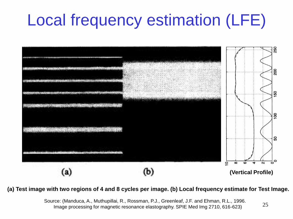
• This software use Local Frequency Estimation (LFE) algorithm to reconstruct elasticity maps from phase data.
• LFE uses the output of different filters to calculate the local spatial frequency of the shear wave propagation.
25
Local frequency estimation (LFE)
(a) Test image with two regions of 4 and 8 cycles per image. (b) Local frequency estimate for Test Image.
Source: (Manduca, A., Muthupillai, R., Rossman, P.J., Greenleaf, J.F. and Ehman, R.L., 1996.
Image processing for magnetic resonance elastography. SPIE Med Img 2710, 616-623)
(Vertical Profile)
26
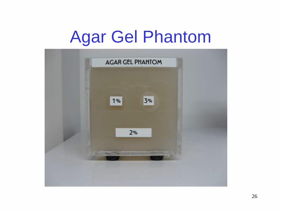
Agar Gel Phantom
27
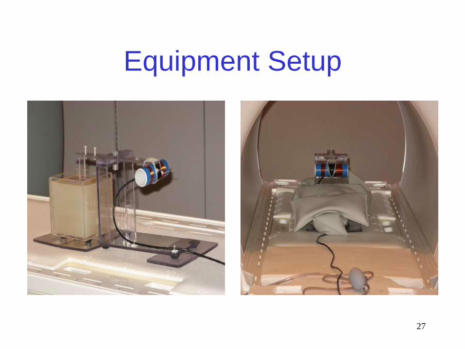
Equipment Setup
28
Experimental procedure
• Sequence Parameters selected:
TR = 120ms / TE = 31.3ms
No of slices = 1, Slice thickness = 5mm
FOV = 20cm X 20cm, Resolution = 256 X 256.
Spine coil Coil used was and no filters selected.
• MRE parameters:
Frequency = 250 Hz and 125 Hz,
MEG amplitude 10mT/m,MEG Cycles = 4
and pre-MEG STIM = 2.
RO MEG ON and other two axes off.
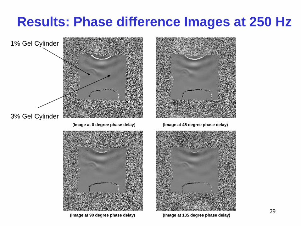
29
Results: Phase difference Images at 250 Hz
(Image at 0 degree phase delay) (Image at 45 degree phase delay)
(Image at 90 degree phase delay) (Image at 135 degree phase delay)
1% Gel Cylinder
3% Gel Cylinder
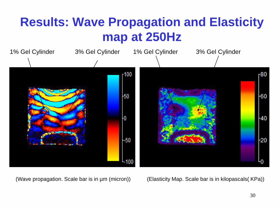
30
Results: Wave Propagation and Elasticity
map at 250Hz
(Wave propagation. Scale bar is in µm (micron)) (Elasticity Map. Scale bar is in kilopascals( KPa))
1% Gel Cylinder 3% Gel Cylinder1% Gel Cylinder 3% Gel Cylinder
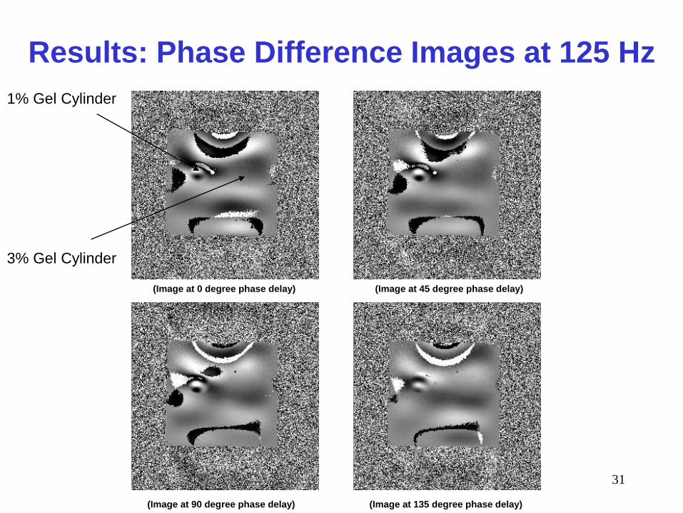
31
Results: Phase Difference Images at 125 Hz
(Image at 0 degree phase delay) (Image at 45 degree phase delay)
(Image at 90 degree phase delay) (Image at 135 degree phase delay)
1% Gel Cylinder
3% Gel Cylinder
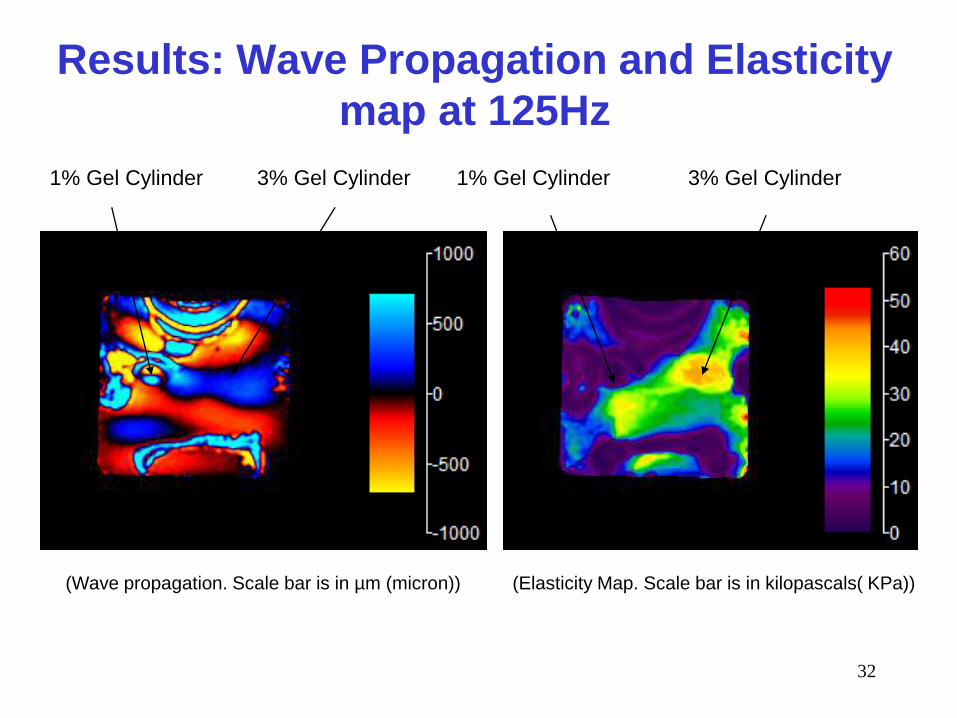
32
Results: Wave Propagation and Elasticity
map at 125Hz
(Wave propagation. Scale bar is in µm (micron)) (Elasticity Map. Scale bar is in kilopascals( KPa))
1% Gel Cylinder 3% Gel Cylinder1% Gel Cylinder 3% Gel Cylinder
33
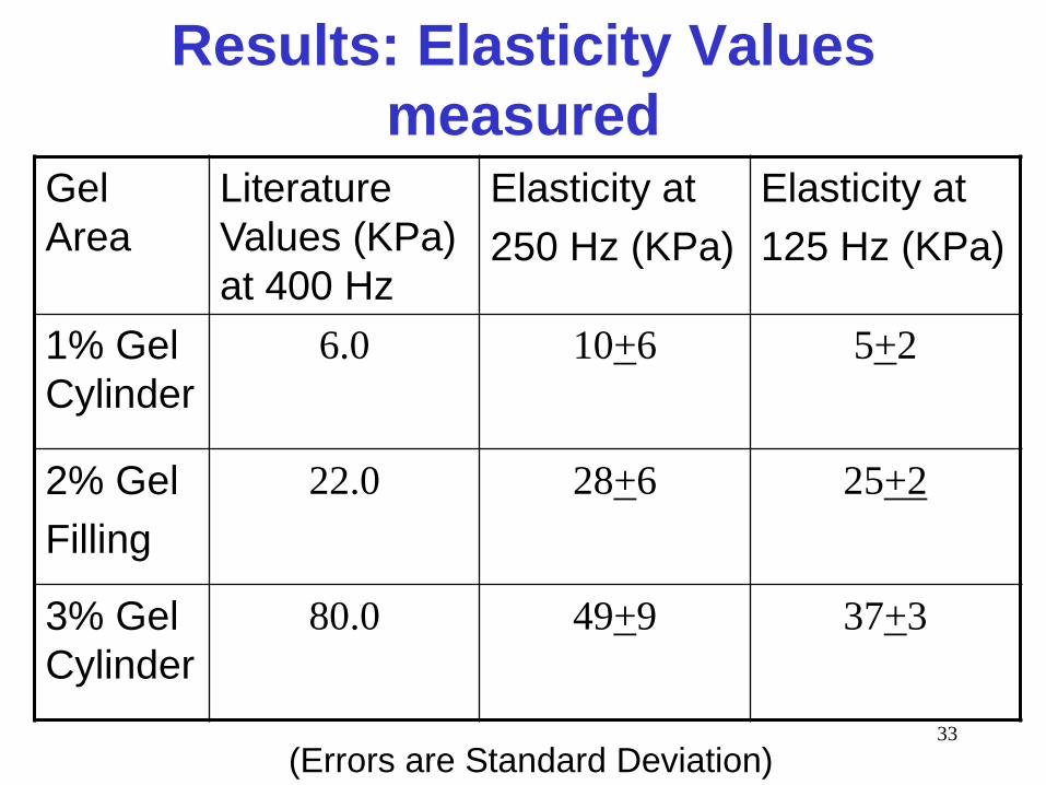
Results: Elasticity Values
measuredGel
Area
Literature
Values (KPa)
at 400 Hz
Elasticity at
250 Hz (KPa)
Elasticity at
125 Hz (KPa)
1% Gel
Cylinder
6.0 10+6 5+2
2% Gel
Filling
22.0 28+6 25+2
3% Gel
Cylinder
80.0 49+9 37+3
(Errors are Standard Deviation)
34
Conclusion
• Elasticity values measured are comparable to the values available in literature.
• Electromagnetic coil has a tendency to produce artifacts.
• Phantom boundary seems to be less elastic because of air and water on the sides.
• Assumption of local homogeneity in reconstruction creates inaccurate results near boundaries and place limit on resolution.
35
Challenges
• Spatial resolution of MRE can be improved by
increasing the frequency, however the high
frequency waves will be attenuated more
rapidly compared to lower frequency waves.
• Sample size needs to accommodate half a
shear wave in the MRE image in order to
measure the stiffness.
• Water and air exists between layers in
phantom damped and distorted the waves.
36
Future Plans: Actuator
• Size of actuator.
• Weight of coil.
• Pivot point needs better design.
• Vertically adjustable actuator head.
• Other types of actuators.
37
Future Plans: Sequence
• Eight different phase offsets in
one motion cycle.
• Modification of Image calculation
part of the sequence.
• Programming of other sequences
like SE for MRE.
38
Future Plans: Reconstruction
Software
• Development of reconstruction
software.
• Use other algorithms like Algebraic
Inversion of the differential equation
or Overlapping subzone technique.
• Addition of new filtering techniques.
39
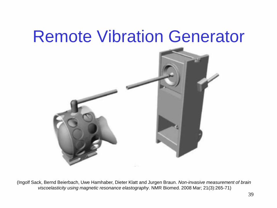
Remote Vibration Generator
(Ingolf Sack, Bernd Beierbach, Uwe Hamhaber, Dieter Klatt and Jurgen Braun. Non-invasive measurement of brain
viscoelasticity using magnetic resonance elastography. NMR Biomed. 2008 Mar; 21(3):265-71)
40
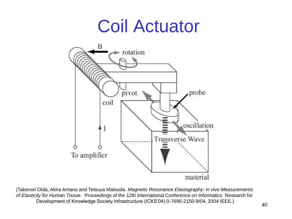
Coil Actuator
(Takenori Oida, Akira Amano and Tetsuya Matsuda. Magnetic Resonance Elastography: in vivo Measurements
of Elasticity for Human Tissue. Proceedings of the 12th International Conference on Informatics Research for
Development of Knowledge Society Infrastructure (ICKS’04) 0-7695-2150-9/04, 2004 IEEE.)
41
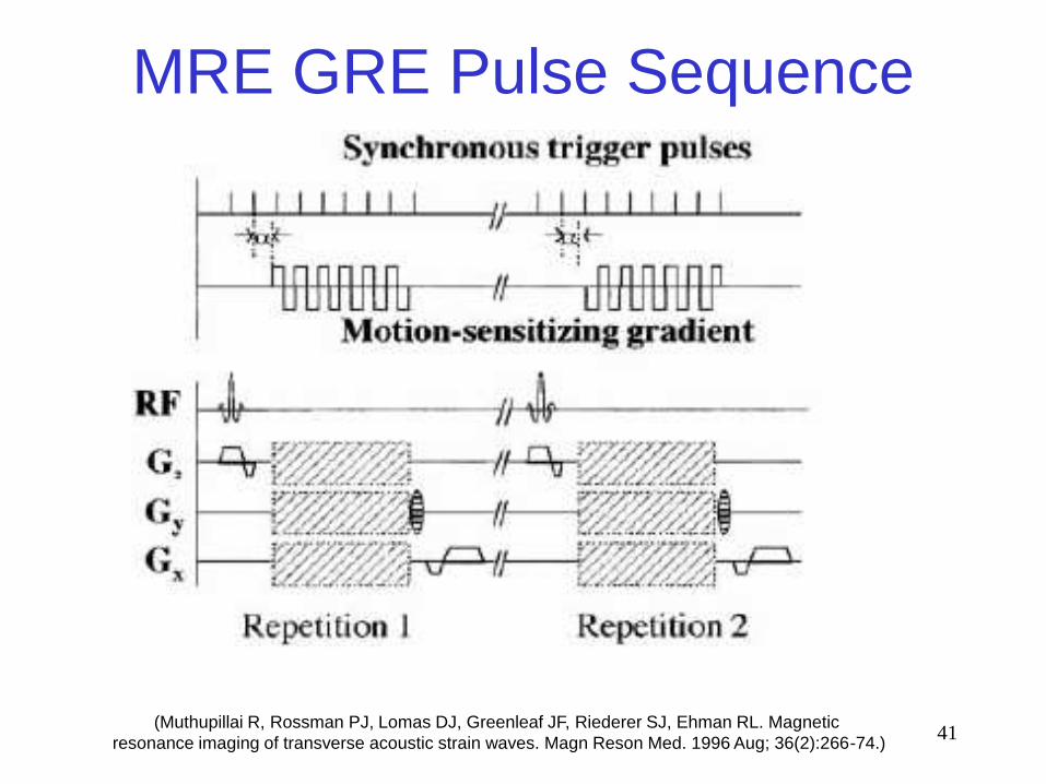
MRE GRE Pulse Sequence
(Muthupillai R, Rossman PJ, Lomas DJ, Greenleaf JF, Riederer SJ, Ehman RL. Magnetic
resonance imaging of transverse acoustic strain waves. Magn Reson Med. 1996 Aug; 36(2):266-74.)
42
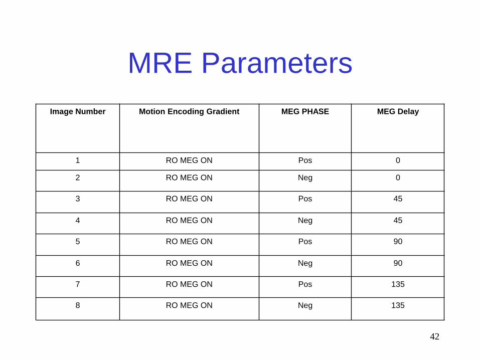
MRE Parameters
Image Number Motion Encoding Gradient MEG PHASE MEG Delay
1 RO MEG ON Pos 0
2 RO MEG ON Neg 0
3 RO MEG ON Pos 45
4 RO MEG ON Neg 45
5 RO MEG ON Pos 90
6 RO MEG ON Neg 90
7 RO MEG ON Pos 135
8 RO MEG ON Neg 135
43
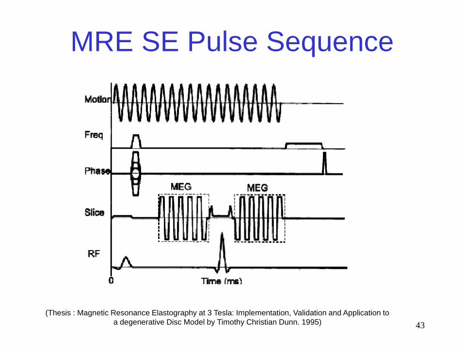
MRE SE Pulse Sequence
(Thesis : Magnetic Resonance Elastography at 3 Tesla: Implementation, Validation and Application to
a degenerative Disc Model by Timothy Christian Dunn. 1995)
44
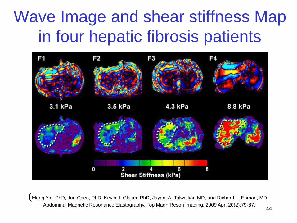
Wave Image and shear stiffness Map
in four hepatic fibrosis patients
(Meng Yin, PhD, Jun Chen, PhD, Kevin J. Glaser, PhD, Jayant A. Talwalkar, MD, and Richard L. Ehman, MD.
Abdominal Magnetic Resonance Elastography. Top Magn Reson Imaging. 2009 Apr; 20(2):79-87.
45
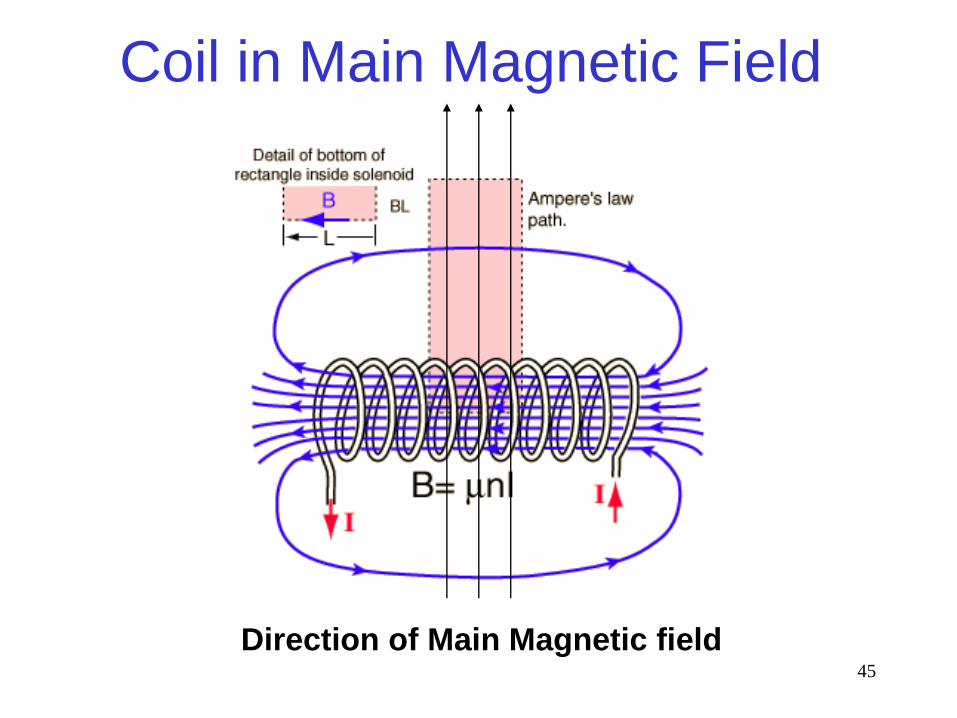
Coil in Main Magnetic Field
Direction of Main Magnetic field
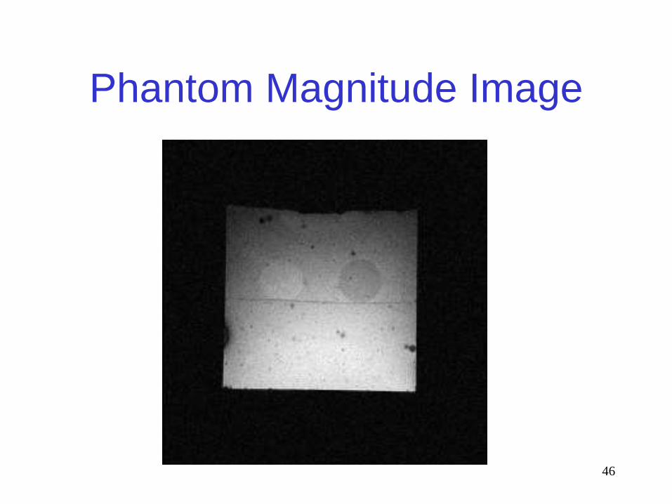
46
Phantom Magnitude Image