Embed Size (px)
Citation preview
1
MPR-3 SERIES NETWORK ANALYSER USER MANUAL
INDEX SAFETY AND WARNINGS ........................................................................................................ 3
Warning .................................................................................................................................. 3
Safety ..................................................................................................................................... 3
Warranty................................................................................................................................. 3
OPERATING CONDITIONS....................................................................................................... 4
INTRODUCTION ....................................................................................................................... 5
General Features ................................................................................................................... 5
Applications ........................................................................................................................... 6
MPR-3 Series Products .......................................................................................................... 6
Overview ................................................................................................................................ 7
Terminals ............................................................................................................................... 7
Front Panel ......................................................................................................................... 8
Button Functions ................................................................................................................. 9
Terminal Structure ............................................................................................................ 10
INSTALLATION ....................................................................................................................... 10
3P4W (3 Phase with Neutral) Connection............................................................................. 10
3P3W (3 Phase without Neutral) Connection........................................................................ 11
Aron without Neutral Connection .......................................................................................... 11
3P4W BLN (3 Phase Balanced with Neutral) Connection ..................................................... 12
3P3W BLN (3 Phase Balanced without Neutral) Connection ................................................ 12
Connection Test ................................................................................................................... 13
Line Termination Resistor..................................................................................................... 13
OPERATING INSTRUCTIONS ................................................................................................ 14
Measurement Screens ......................................................................................................... 14
Current, Voltage and Frequency Screens ......................................................................... 14
Power and Power Factor Screens..................................................................................... 15
Energy and Harmonics Screens........................................................................................ 17
Minimum, Maximum and Demand Screens ....................................................................... 19
2
Setup Screen........................................................................................................................ 25
Device Installation Settings .............................................................................................. 25
Display Settings ............................................................................................................... 30
Time Settings ................................................................................................................... 31
RS-485 Communication Settings ..................................................................................... 33
Input Parameter Settings .................................................................................................. 34
Output Parameter Settings................................................................................................ 35
Pulse Output Settings ....................................................................................................... 36
Operating Hours Settings .................................................................................................. 38
Alarm Settings ................................................................................................................. 39
Reset Settings .................................................................................................................. 42
System Settings ................................................................................................................ 44
Reporting Screen .............................................................................................................. 47
Reading the Records via Modbus ..................................................................................... 48
TECHNICAL FEATURES AND APPENDIX ............................................................................. 49
Technical Features ............................................................................................................... 49
Applicable Standards ........................................................................................................ 50
IEC 61557-12.................................................................................................................... 50
3
SAFETY AND WARNINGS
Warning
Failure to follow the instructions below may result in serious injury or death.
Cut all power before connecting the device.
Do not connect the current measurement inputs directly to the current source. Always connect
the current source using a current transformer.
Once the device is energized, do not remove the front panel.
Do not attempt to clean the device with a solvent or another similar agent. Use only a dry piece of
cloth.
Check the correct connections before energizing the device.
Contact your authorized seller in case of any problems with your device.
Device is only for panel mounting.
F Type fuse must be used and its current limit must be 1 A. The manufacturing company is not responsible for the consequences resulting from failure to comply with these precautions.
Safety
Read the entire user manual before using the device.
A switch or circuit breaker must be connected between the network and the auxiliary supply of
the device.
Connected switch or circuit breaker must be in close proximity to the device.
Connected switch or circuit breaker must be marked as the disconnecting device for the equipment.
Warranty Device has a 2 (two) year warranty. Any repairs on the device must be done only by the manufacturer. Otherwise, the device warranty will be void.
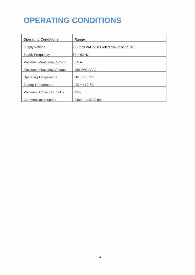
OPERATING CONDITIONS
Operating Conditions
Range Supply Voltage
95 - 270 VAC/VDC(Tolerance up to ±10%) (Tolerances up to ± 10%)
Supply Frequency 50 ~ 60 Hz.
Maximum Measuring Current
5,5 A
Maximum Measuring Voltage
480 VAC (VLL)
Operating Temperature
-10 ~ +55 ºC
Storing Temperature
-20 ~ +70 ºC
Maximum Ambient Humidity
95%
Communication Speed
2400 ~ 115200 bps
4
5
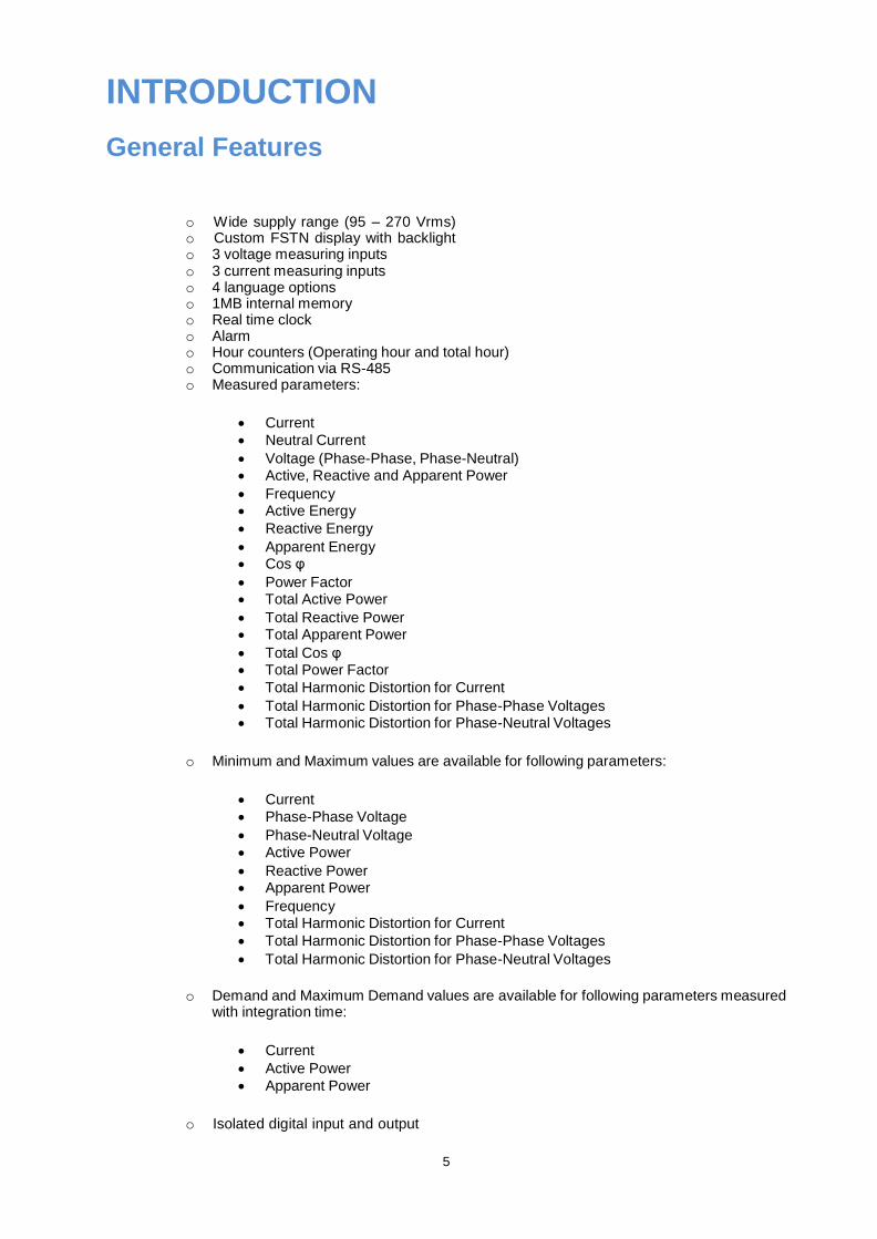
INTRODUCTION
General Features
o Wide supply range (95 – 270 Vrms) o Custom FSTN display with backlight o 3 voltage measuring inputs o 3 current measuring inputs o 4 language options o 1MB internal memory o Real time clock o Alarm o Hour counters (Operating hour and total hour) o Communication via RS-485 o Measured parameters:
Current
Neutral Current
Voltage (Phase-Phase, Phase-Neutral)
Active, Reactive and Apparent Power
Frequency
Active Energy
Reactive Energy
Apparent Energy
Cos φ
Power Factor
Total Active Power
Total Reactive Power
Total Apparent Power
Total Cos φ
Total Power Factor
Total Harmonic Distortion for Current
Total Harmonic Distortion for Phase-Phase Voltages
Total Harmonic Distortion for Phase-Neutral Voltages
o Minimum and Maximum values are available for following parameters:
Current
Phase-Phase Voltage
Phase-Neutral Voltage
Active Power
Reactive Power
Apparent Power
Frequency
Total Harmonic Distortion for Current
Total Harmonic Distortion for Phase-Phase Voltages
Total Harmonic Distortion for Phase-Neutral Voltages
o Demand and Maximum Demand values are available for following parameters measured
with integration time:
Current
Active Power
Apparent Power
o Isolated digital input and output
6
o Capable of recording 256 events o User password o Changing primary and secondary values of current and voltage transformers o Making measurements on 5 different connection type systems: 3 Phase 4 Wires, 3
Phase 3 Wires, 3 Phase Aron, 3 Phase 4 Wires Balanced, 3 Phase 3 Wires Balanced o Contrast setting o Backlight setting o Demand and integration time setting o Daylight savings time switching
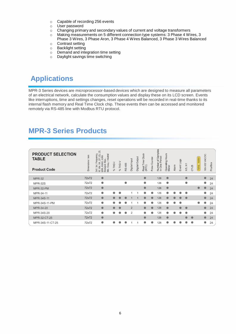
Applications MPR-3 Series devices are microprocessor-based devices which are designed to measure all parameters of an electrical network, calculate the consumption values and display these on its LCD screen. Events like interruptions, time and settings changes, reset operations will be recorded in real-time thanks to its internal flash memory and Real Time Clock chip. These events then can be accessed and monitored remotely via RS-485 line with Modbus RTU protocol.
MPR-3 Series Products
7
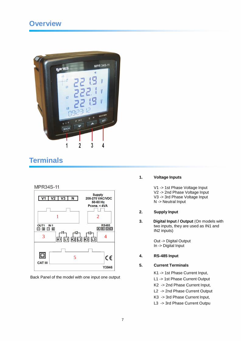
Overview
Terminals
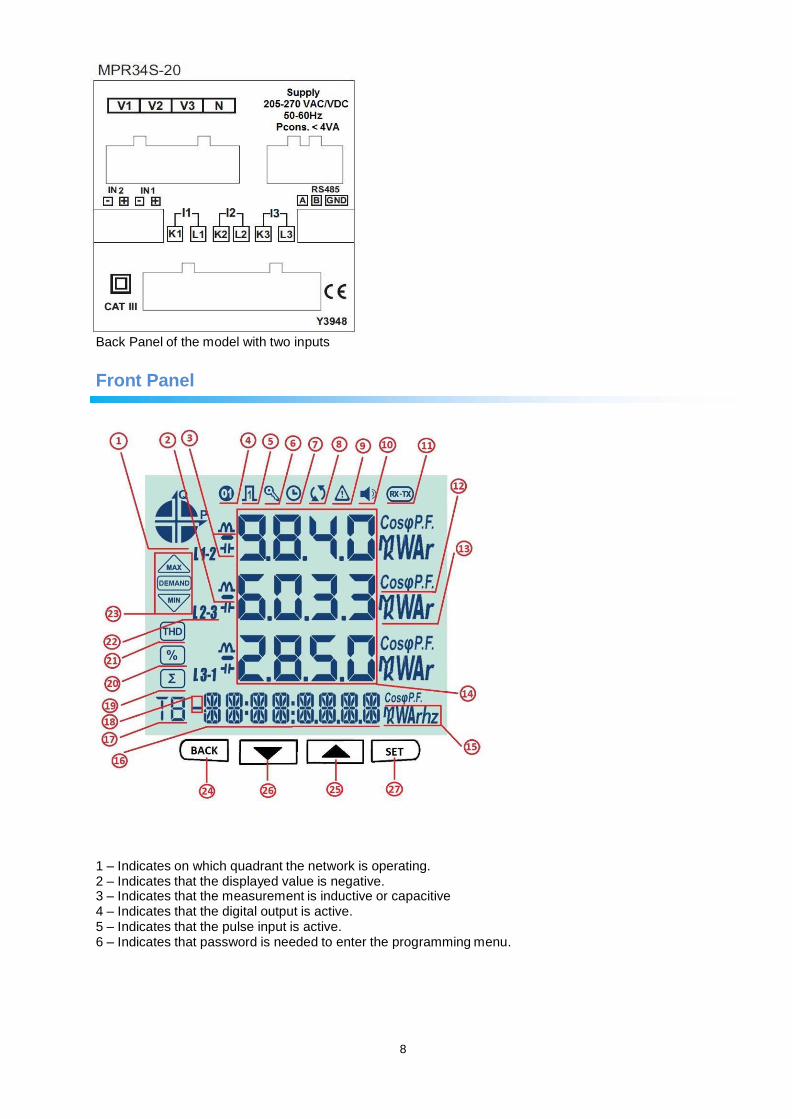
1. Voltage Inputs
V1 -> 1st Phase Voltage Input V2 -> 2nd Phase Voltage Input V3 -> 3rd Phase Voltage Input N -> Neutral Input
2. Supply Input
3. Digital Input / Output (On models with
two inputs, they are used as IN1 and IN2 inputs)
Out -> Digital Output In -> Digital Input
4. RS-485 Input
5. Current Terminals
Back Panel of the model with one input one output
K1 -> 1st Phase Current Input,
L1 -> 1st Phase Current Output
K2 -> 2nd Phase Current Input,
L2 -> 2nd Phase Current Output
K3 -> 3rd Phase Current Input,
L3 -> 3rd Phase Current Outpu
1 2
3 4
5
1 2
3 4
5
8
Back Panel of the model with two inputs
Front Panel
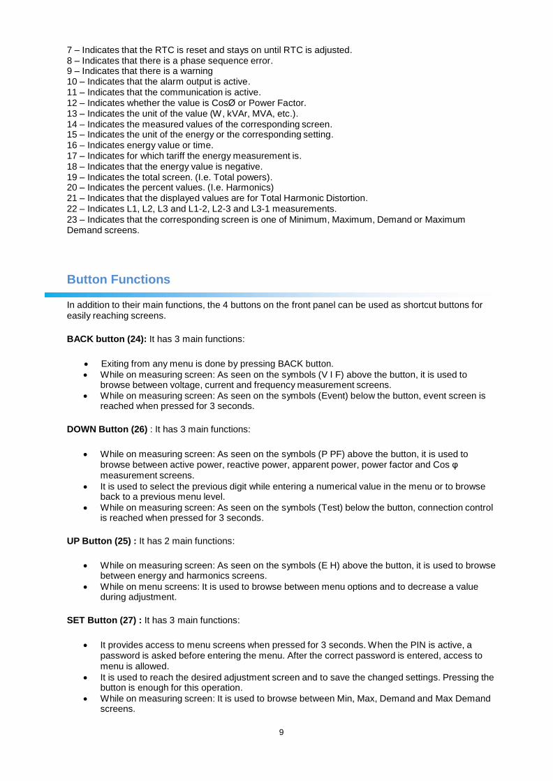
1 – Indicates on which quadrant the network is operating. 2 – Indicates that the displayed value is negative. 3 – Indicates that the measurement is inductive or capacitive 4 – Indicates that the digital output is active. 5 – Indicates that the pulse input is active. 6 – Indicates that password is needed to enter the programming menu.
9
7 – Indicates that the RTC is reset and stays on until RTC is adjusted. 8 – Indicates that there is a phase sequence error. 9 – Indicates that there is a warning 10 – Indicates that the alarm output is active. 11 – Indicates that the communication is active. 12 – Indicates whether the value is CosØ or Power Factor. 13 – Indicates the unit of the value (W, kVAr, MVA, etc.). 14 – Indicates the measured values of the corresponding screen. 15 – Indicates the unit of the energy or the corresponding setting. 16 – Indicates energy value or time. 17 – Indicates for which tariff the energy measurement is. 18 – Indicates that the energy value is negative. 19 – Indicates the total screen. (I.e. Total powers). 20 – Indicates the percent values. (I.e. Harmonics) 21 – Indicates that the displayed values are for Total Harmonic Distortion. 22 – Indicates L1, L2, L3 and L1-2, L2-3 and L3-1 measurements. 23 – Indicates that the corresponding screen is one of Minimum, Maximum, Demand or Maximum Demand screens.
Button Functions In addition to their main functions, the 4 buttons on the front panel can be used as shortcut buttons for easily reaching screens.
BACK button (24): It has 3 main functions:
Exiting from any menu is done by pressing BACK button.
While on measuring screen: As seen on the symbols (V I F) above the button, it is used to browse between voltage, current and frequency measurement screens.
While on measuring screen: As seen on the symbols (Event) below the button, event screen is reached when pressed for 3 seconds.
DOWN Button (26) : It has 3 main functions:
While on measuring screen: As seen on the symbols (P PF) above the button, it is used to
browse between active power, reactive power, apparent power, power factor and Cos φ measurement screens.
It is used to select the previous digit while entering a numerical value in the menu or to browse back to a previous menu level.
While on measuring screen: As seen on the symbols (Test) below the button, connection control is reached when pressed for 3 seconds.
UP Button (25) : It has 2 main functions:
While on measuring screen: As seen on the symbols (E H) above the button, it is used to browse
between energy and harmonics screens.
While on menu screens: It is used to browse between menu options and to decrease a value during adjustment.
SET Button (27) : It has 3 main functions:
It provides access to menu screens when pressed for 3 seconds. When the PIN is active, a
password is asked before entering the menu. After the correct password is entered, access to menu is allowed.
It is used to reach the desired adjustment screen and to save the changed settings. Pressing the button is enough for this operation.
While on measuring screen: It is used to browse between Min, Max, Demand and Max Demand screens.
10
Terminal Structure
1) 185 - 300 VAC/VDC Supply Input 3 terminal connections (2 pins)
2) Current measuring input terminal block (6 pins): L1 L2 L3 ve N
3) Voltage measuring input terminal block (4 pins): L1 L2 L3 and N
4) RS-485 terminal block (2 pins)
5) Digital Input/Output terminal (4 pins)
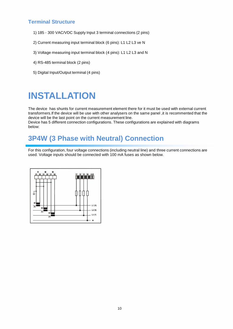
INSTALLATION The device has shunts for current measurement element there for it must be used with external current transformers.If the device will be use with other analysers on the same panel ,it is recommented that the device will be the last point on the current measurement line. Device has 5 different connection configurations. These configurations are explained with diagrams below:
3P4W (3 Phase with Neutral) Connection For this configuration, four voltage connections (including neutral line) and three current connections are used. Voltage inputs should be connected with 100 mA fuses as shown below.
11
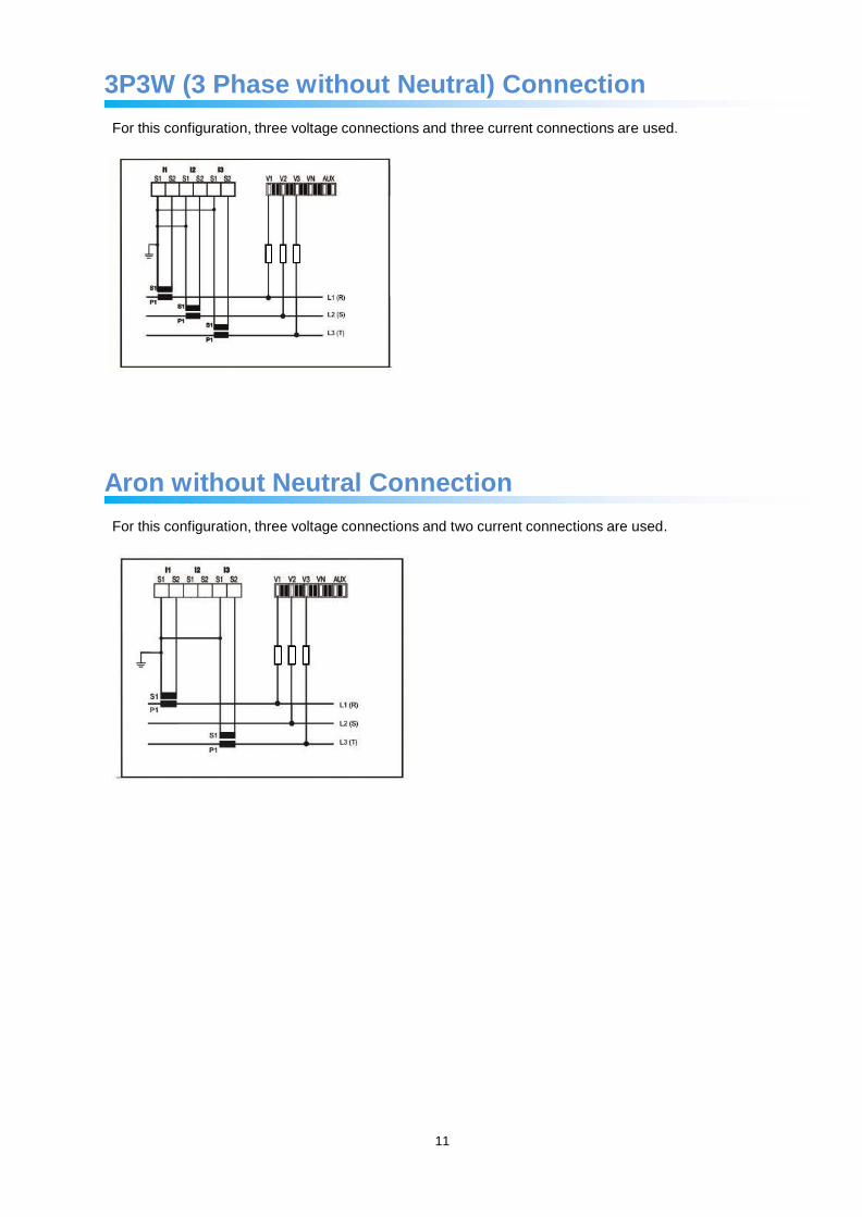
3P3W (3 Phase without Neutral) Connection
For this configuration, three voltage connections and three current connections are used.
Aron without Neutral Connection
For this configuration, three voltage connections and two current connections are used.
12
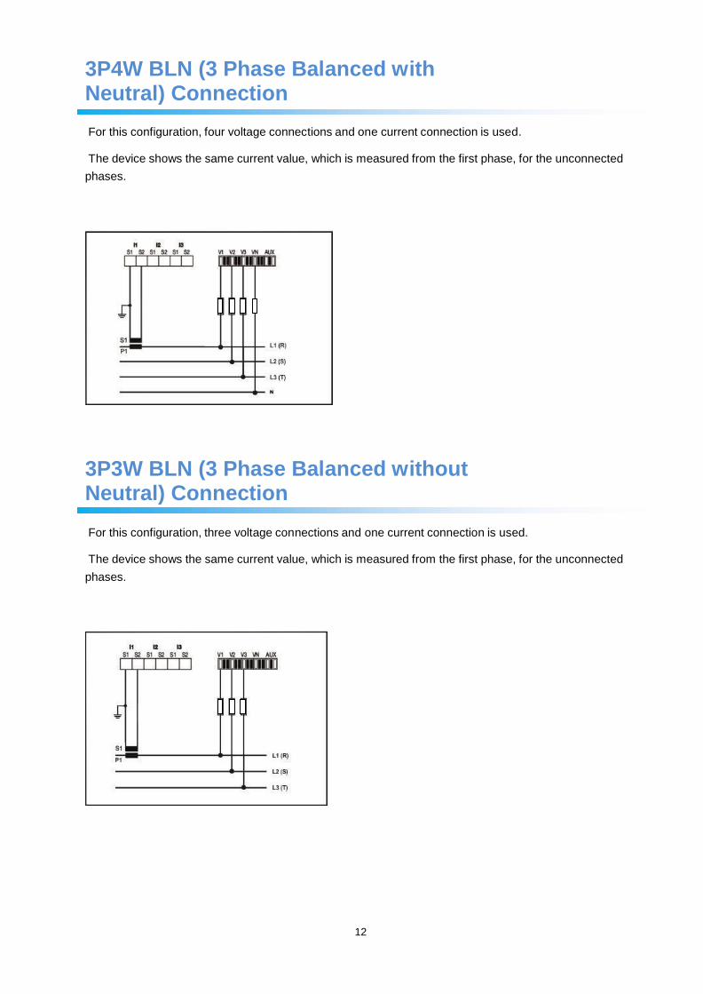
3P4W BLN (3 Phase Balanced with Neutral) Connection
For this configuration, four voltage connections and one current connection is used.
The device shows the same current value, which is measured from the first phase, for the unconnected
phases.
3P3W BLN (3 Phase Balanced without Neutral) Connection
For this configuration, three voltage connections and one current connection is used.
The device shows the same current value, which is measured from the first phase, for the unconnected
phases.
13
Connection Test
After finishing device connections, you can check the connection that you’ve done by using the automatic test function.
When you press the BACK button for 3 seconds, it switches to test mode. During this mode, at least 20% of the nominal voltage must be applied to the voltage measuring inputs, at least 10% of the nominal current must be applied to the current measuring inputs and the angle difference between current and voltage inputs must be less than 30 degrees. These test conditions must be met.
During connection test, the device controls the connections and it can correct them internally or it can leave the physical correction to the user.
If there’s an error between voltage inputs, it can only be corrected by changing physical connections.
If you encounter Error 12, make sure that all connections are done and minimum current/voltage values are applied to the device.
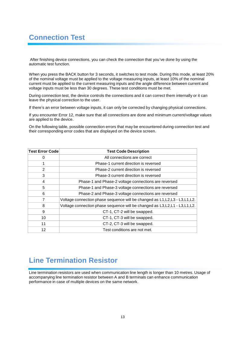
On the following table, possible connection errors that may be encountered during connection test and their corresponding error codes that are displayed on the device screen.
Test Error Code Test Code Description
0 All connections are correct
1 Phase-1 current direction is reversed
2 Phase-2 current direction is reversed
3 Phase-3 current direction is reversed
4 Phase-1 and Phase-2 voltage connections are reversed
5 Phase-1 and Phase-3 voltage connections are reversed
6 Phase-2 and Phase-3 voltage connections are reversed
7 Voltage connection phase sequence will be changed as L1,L2,L3 - L3,L1,L2.
8 Voltage connection phase sequence will be changed as L3,L2,L1 - L3,L1,L2.
9 CT-1, CT-2 will be swapped.
10 CT-1, CT-3 will be swapped.
11 CT-2, CT-3 will be swapped.
12 Test conditions are not met.
Line Termination Resistor
Line termination resistors are used when communication line length is longer than 10 metres. Usage of accompanying line termination resistor between A and B terminals can enhance communication performance in case of multiple devices on the same network.
14
OPERATING INSTRUCTIONS
Measurement Screens
Measurement screens, which can be accessed by pressing the related buttons, are explained in this section.
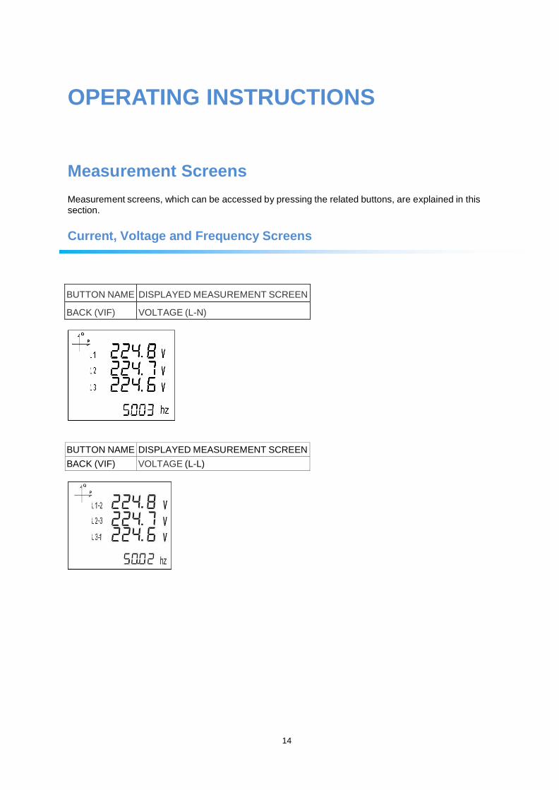
Current, Voltage and Frequency Screens
BUTTON NAME DISPLAYED MEASUREMENT SCREEN
BACK (VIF)
VOLTAGE (L-N)
BUTTON NAME DISPLAYED MEASUREMENT SCREEN
BACK (VIF) VOLTAGE (L-L)
BUTTON NAME DISPLAYED MEASUREMENT SCREEN
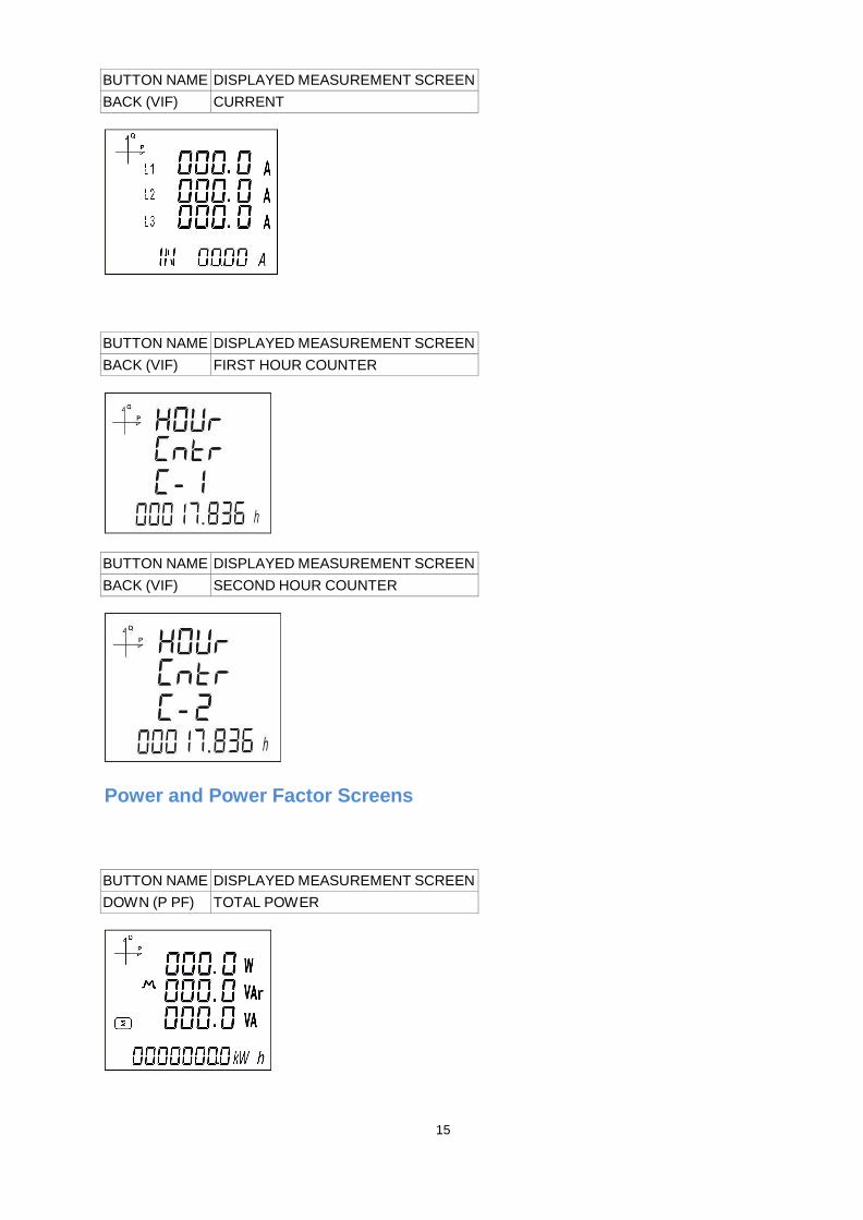
BACK (VIF) CURRENT
BUTTON NAME DISPLAYED MEASUREMENT SCREEN
BACK (VIF) FIRST HOUR COUNTER
BUTTON NAME DISPLAYED MEASUREMENT SCREEN
BACK (VIF) SECOND HOUR COUNTER
Power and Power Factor Screens
BUTTON NAME DISPLAYED MEASUREMENT SCREEN
DOWN (P PF) TOTAL POWER
15
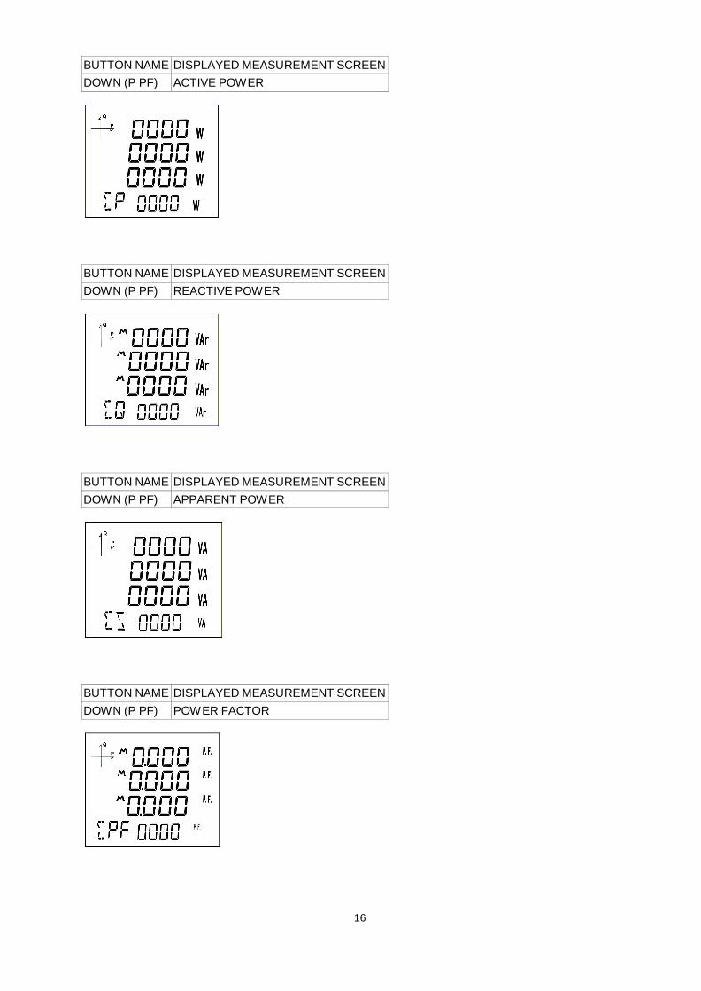
BUTTON NAME DISPLAYED MEASUREMENT SCREEN
DOWN (P PF) ACTIVE POWER
BUTTON NAME DISPLAYED MEASUREMENT SCREEN
DOWN (P PF) REACTIVE POWER
BUTTON NAME DISPLAYED MEASUREMENT SCREEN
DOWN (P PF) APPARENT POWER
BUTTON NAME DISPLAYED MEASUREMENT SCREEN
DOWN (P PF) POWER FACTOR
16
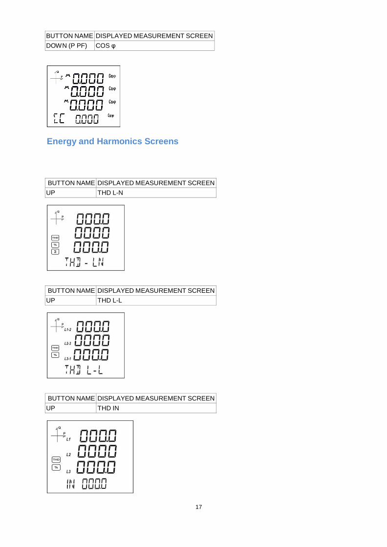
BUTTON NAME DISPLAYED MEASUREMENT SCREEN
DOWN (P PF) COS φ
Energy and Harmonics Screens
BUTTON NAME DISPLAYED MEASUREMENT SCREEN
UP THD L-N
BUTTON NAME DISPLAYED MEASUREMENT SCREEN
UP THD L-L
BUTTON NAME DISPLAYED MEASUREMENT SCREEN
UP THD IN
17
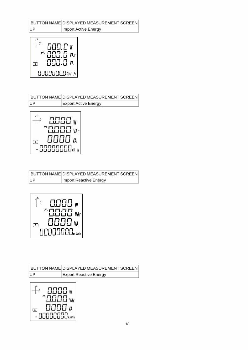
BUTTON NAME DISPLAYED MEASUREMENT SCREEN
UP Import Active Energy
BUTTON NAME DISPLAYED MEASUREMENT SCREEN
UP Export Active Energy
BUTTON NAME DISPLAYED MEASUREMENT SCREEN
UP Import Reactive Energy
BUTTON NAME DISPLAYED MEASUREMENT SCREEN
UP Export Reactive Energy
18
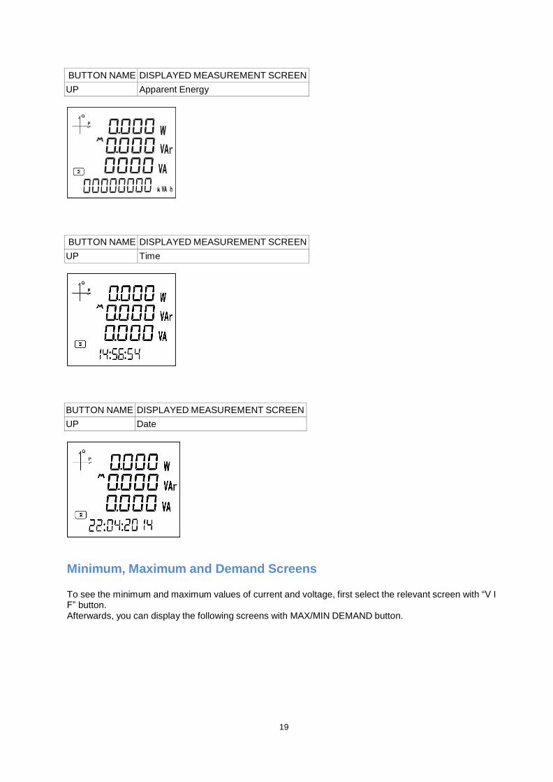
BUTTON NAME DISPLAYED MEASUREMENT SCREEN
UP Apparent Energy
BUTTON NAME DISPLAYED MEASUREMENT SCREEN
UP Time
BUTTON NAME DISPLAYED MEASUREMENT SCREEN
UP Date
Minimum, Maximum and Demand Screens
To see the minimum and maximum values of current and voltage, first select the relevant screen with “V I F” button. Afterwards, you can display the following screens with MAX/MIN DEMAND button.
19
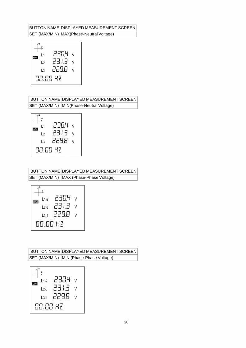
BUTTON NAME DISPLAYED MEASUREMENT SCREEN
SET (MAX/MIN) MAX(Phase-Neutral Voltage)
BUTTON NAME DISPLAYED MEASUREMENT SCREEN
SET (MAX/MIN) MIN(Phase-Neutral Voltage)
BUTTON NAME DISPLAYED MEASUREMENT SCREEN
SET (MAX/MIN) MAX (Phase-Phase Voltage)
BUTTON NAME DISPLAYED MEASUREMENT SCREEN
SET (MAX/MIN) MIN (Phase-Phase Voltage)
20
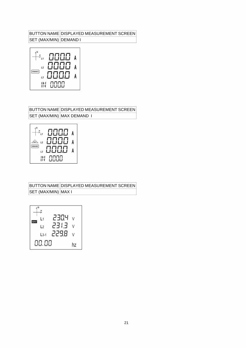
BUTTON NAME DISPLAYED MEASUREMENT SCREEN
SET (MAX/MIN) DEMAND I
BUTTON NAME DISPLAYED MEASUREMENT SCREEN
SET (MAX/MIN) MAX DEMAND I
BUTTON NAME DISPLAYED MEASUREMENT SCREEN
SET (MAX/MIN) MAX I
21
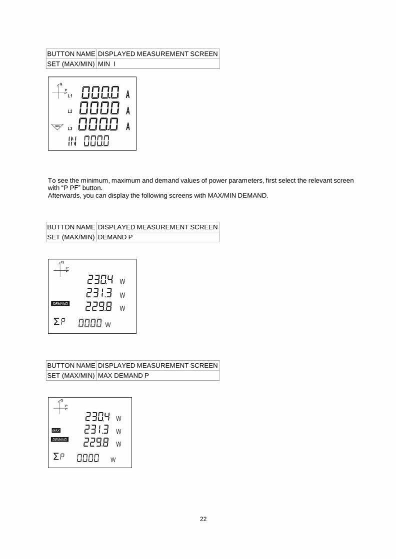
BUTTON NAME DISPLAYED MEASUREMENT SCREEN
SET (MAX/MIN) MIN I
To see the minimum, maximum and demand values of power parameters, first select the relevant screen with “P PF” button. Afterwards, you can display the following screens with MAX/MIN DEMAND.
BUTTON NAME DISPLAYED MEASUREMENT SCREEN
SET (MAX/MIN) DEMAND P
BUTTON NAME DISPLAYED MEASUREMENT SCREEN
SET (MAX/MIN) MAX DEMAND P
22
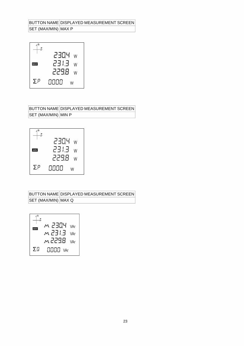
BUTTON NAME DISPLAYED MEASUREMENT SCREEN
SET (MAX/MIN) MAX P
BUTTON NAME DISPLAYED MEASUREMENT SCREEN
SET (MAX/MIN) MIN P
BUTTON NAME DISPLAYED MEASUREMENT SCREEN
SET (MAX/MIN) MAX Q
23
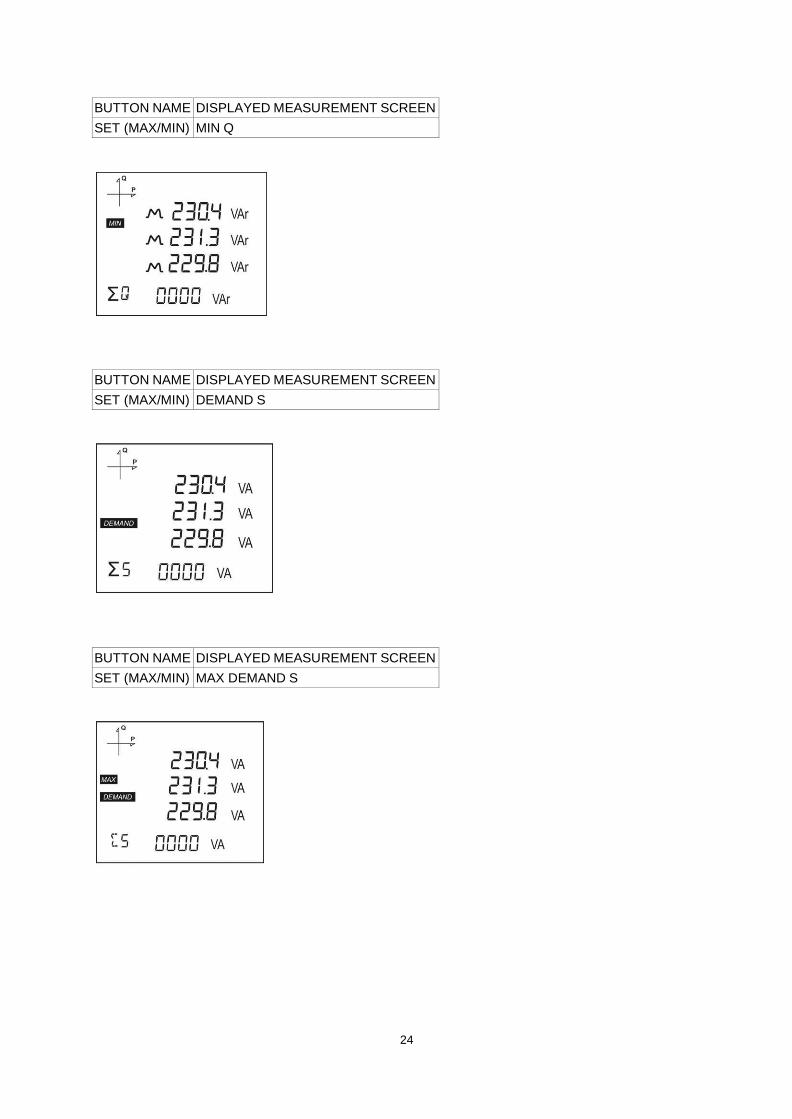
BUTTON NAME DISPLAYED MEASUREMENT SCREEN
SET (MAX/MIN) MIN Q
BUTTON NAME DISPLAYED MEASUREMENT SCREEN
SET (MAX/MIN) DEMAND S
BUTTON NAME DISPLAYED MEASUREMENT SCREEN
SET (MAX/MIN) MAX DEMAND S
24
25
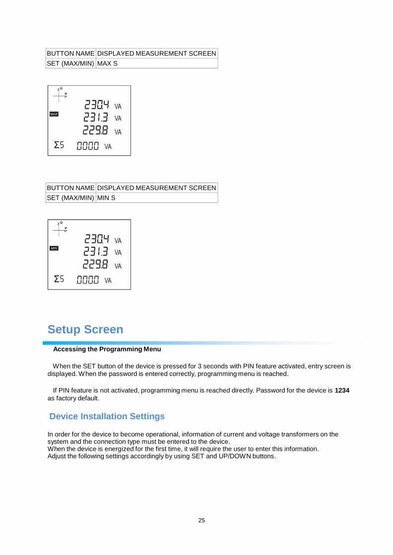
BUTTON NAME DISPLAYED MEASUREMENT SCREEN
SET (MAX/MIN) MAX S
BUTTON NAME DISPLAYED MEASUREMENT SCREEN
SET (MAX/MIN) MIN S
Setup Screen
Accessing the Programming Menu
When the SET button of the device is pressed for 3 seconds with PIN feature activated, entry screen is
displayed. When the password is entered correctly, programming menu is reached.
If PIN feature is not activated, programming menu is reached directly. Password for the device is 1234
as factory default.
Device Installation Settings
In order for the device to become operational, information of current and voltage transformers on the system and the connection type must be entered to the device. When the device is energized for the first time, it will require the user to enter this information. Adjust the following settings accordingly by using SET and UP/DOWN buttons.
26
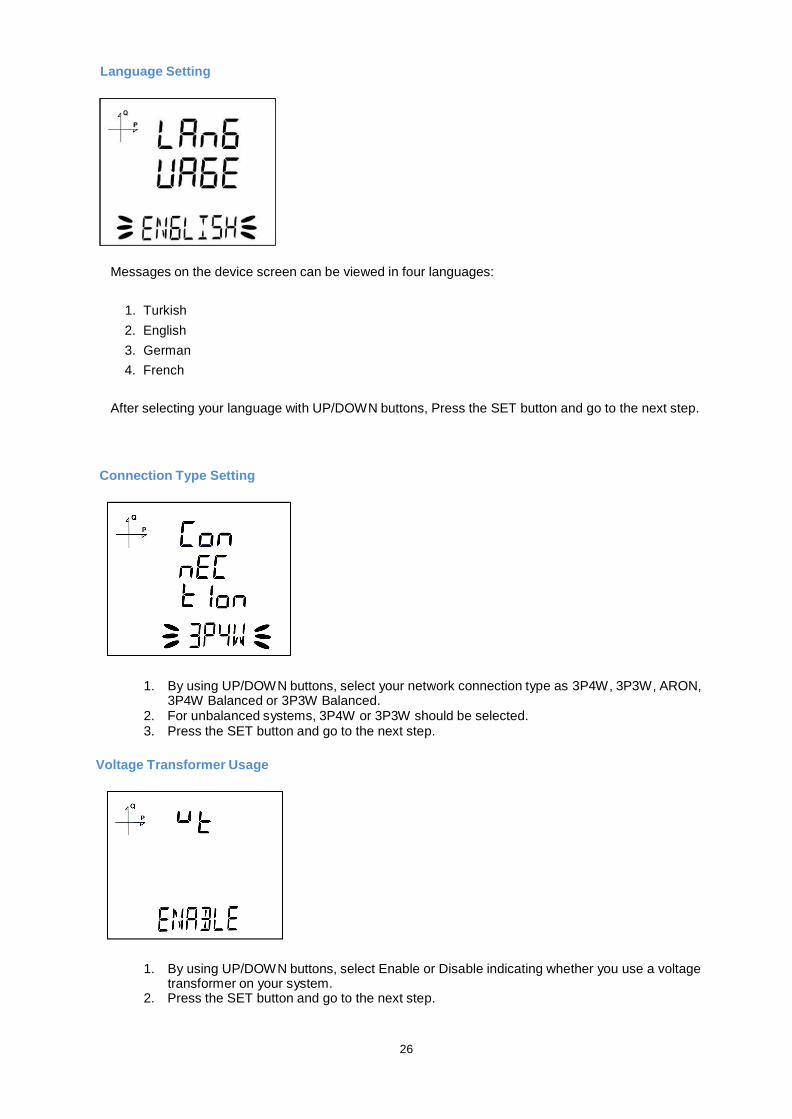
Language Setting
Messages on the device screen can be viewed in four languages:
1. Turkish
2. English
3. German
4. French
After selecting your language with UP/DOWN buttons, Press the SET button and go to the next step.
Connection Type Setting
1. By using UP/DOWN buttons, select your network connection type as 3P4W, 3P3W, ARON,
3P4W Balanced or 3P3W Balanced. 2. For unbalanced systems, 3P4W or 3P3W should be selected. 3. Press the SET button and go to the next step.
Voltage Transformer Usage
1. By using UP/DOWN buttons, select Enable or Disable indicating whether you use a voltage
transformer on your system. 2. Press the SET button and go to the next step.
27
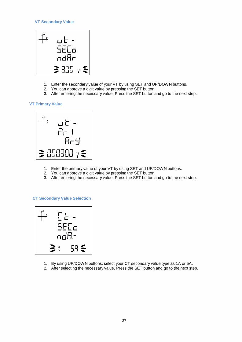
VT Secondary Value
1. Enter the secondary value of your VT by using SET and UP/DOWN buttons. 2. You can approve a digit value by pressing the SET button. 3. After entering the necessary value, Press the SET button and go to the next step.
VT Primary Value
1. Enter the primary value of your VT by using SET and UP/DOWN buttons. 2. You can approve a digit value by pressing the SET button. 3. After entering the necessary value, Press the SET button and go to the next step.
CT Secondary Value Selection
1. By using UP/DOWN buttons, select your CT secondary value type as 1A or 5A. 2. After selecting the necessary value, Press the SET button and go to the next step.
28
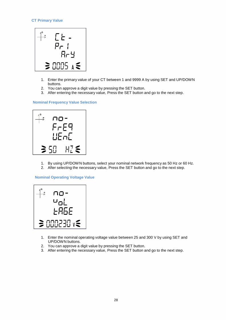
CT Primary Value
1. Enter the primary value of your CT between 1 and 9999 A by using SET and UP/DOWN
buttons. 2. You can approve a digit value by pressing the SET button. 3. After entering the necessary value, Press the SET button and go to the next step.
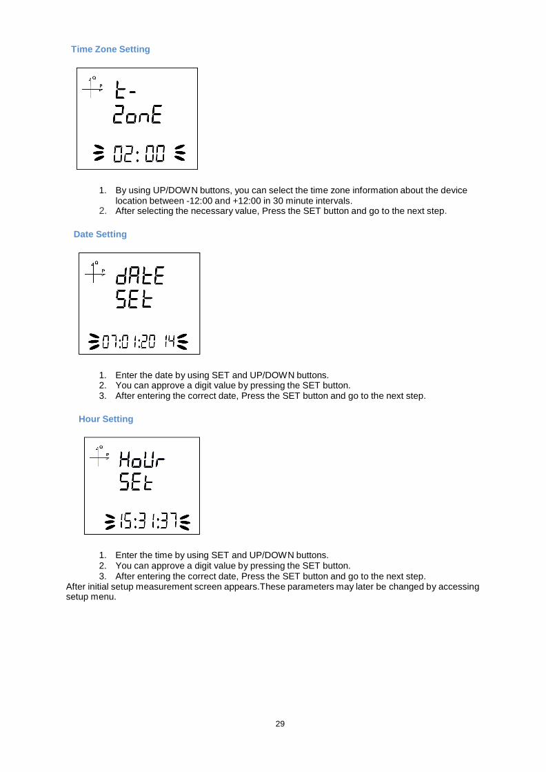
Nominal Frequency Value Selection
1. By using UP/DOWN buttons, select your nominal network frequency as 50 Hz or 60 Hz. 2. After selecting the necessary value, Press the SET button and go to the next step.
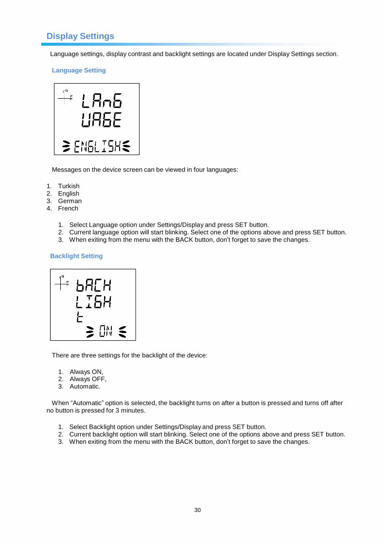
Nominal Operating Voltage Value
1. Enter the nominal operating voltage value between 25 and 300 V by using SET and
UP/DOWN buttons. 2. You can approve a digit value by pressing the SET button. 3. After entering the necessary value, Press the SET button and go to the next step.
29
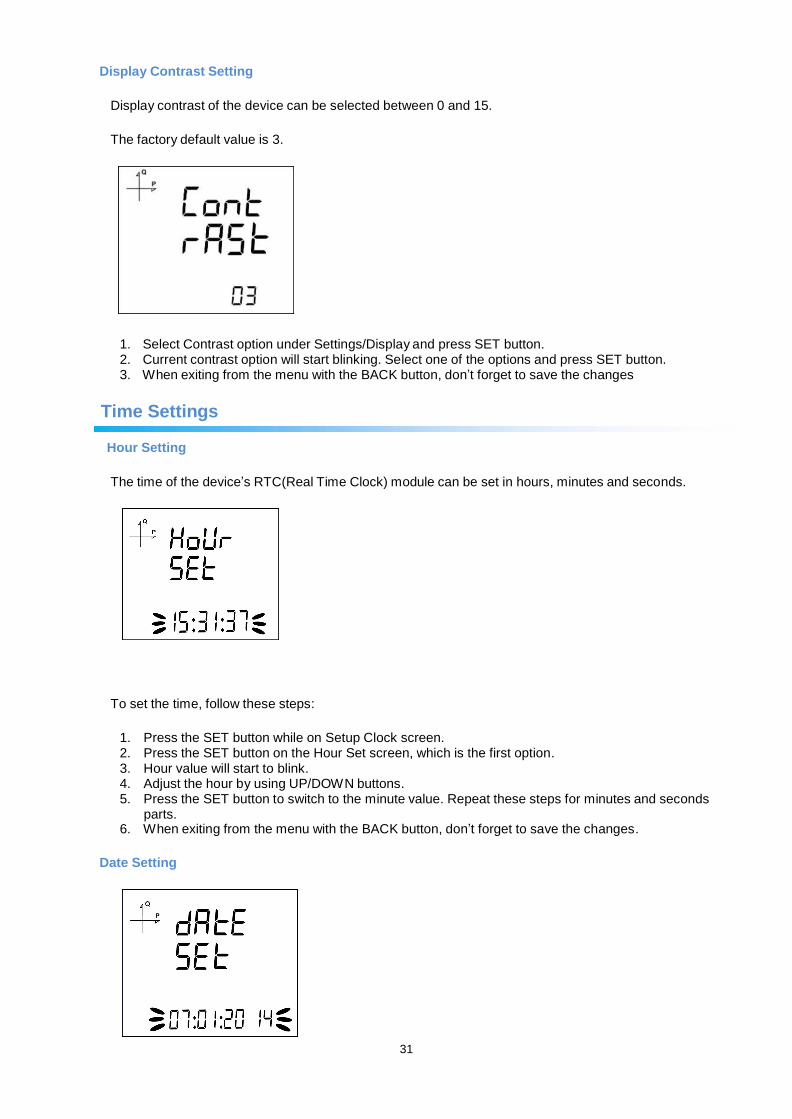
Time Zone Setting
1. By using UP/DOWN buttons, you can select the time zone information about the device
location between -12:00 and +12:00 in 30 minute intervals. 2. After selecting the necessary value, Press the SET button and go to the next step.
Date Setting
1. Enter the date by using SET and UP/DOWN buttons. 2. You can approve a digit value by pressing the SET button. 3. After entering the correct date, Press the SET button and go to the next step.
Hour Setting
1. Enter the time by using SET and UP/DOWN buttons. 2. You can approve a digit value by pressing the SET button. 3. After entering the correct date, Press the SET button and go to the next step.
After initial setup measurement screen appears.These parameters may later be changed by accessing setup menu.
30
Display Settings
Language settings, display contrast and backlight settings are located under Display Settings section.
Language Setting
Messages on the device screen can be viewed in four languages:
1. Turkish 2. English 3. German 4. French
1. Select Language option under Settings/Display and press SET button. 2. Current language option will start blinking. Select one of the options above and press SET button. 3. When exiting from the menu with the BACK button, don’t forget to save the changes.
Backlight Setting
There are three settings for the backlight of the device:
1. Always ON, 2. Always OFF, 3. Automatic.
When “Automatic” option is selected, the backlight turns on after a button is pressed and turns off after
no button is pressed for 3 minutes.
1. Select Backlight option under Settings/Display and press SET button. 2. Current backlight option will start blinking. Select one of the options above and press SET button. 3. When exiting from the menu with the BACK button, don’t forget to save the changes.
31
Display Contrast Setting
Display contrast of the device can be selected between 0 and 15.
The factory default value is 3.
1. Select Contrast option under Settings/Display and press SET button. 2. Current contrast option will start blinking. Select one of the options and press SET button. 3. When exiting from the menu with the BACK button, don’t forget to save the changes
Time Settings
Hour Setting
The time of the device’s RTC(Real Time Clock) module can be set in hours, minutes and seconds.
To set the time, follow these steps:
1. Press the SET button while on Setup Clock screen. 2. Press the SET button on the Hour Set screen, which is the first option. 3. Hour value will start to blink. 4. Adjust the hour by using UP/DOWN buttons. 5. Press the SET button to switch to the minute value. Repeat these steps for minutes and seconds
parts. 6. When exiting from the menu with the BACK button, don’t forget to save the changes.
Date Setting
32
The date of the device’s RTC module can be set in hours, minutes and seconds.
To set the date, follow these steps:
1. Press the SET button on the Date Set screen. 2. Press the SET button. Adjust the day with UP/DOWN buttons. 3. Press the SET button. Adjust the month with UP/DOWN buttons. 4. Press the SET button. Adjust the year with UP/DOWN buttons. 5. When exiting from the menu with the BACK button, don’t forget to save the changes.
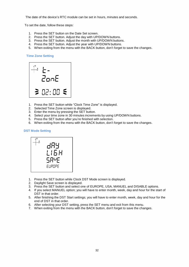
Time Zone Setting
1. Press the SET button while “Clock Time Zone” is displayed. 2. Selected Time Zone screen is displayed. 3. Enter the menu by pressing the SET button. 4. Select your time zone in 30 minutes increments by using UP/DOWN buttons. 5. Press the SET button after you’re finished with selection. 6. When exiting from the menu with the BACK button, don’t forget to save the changes.
DST Mode Setting
1. Press the SET button while Clock DST Mode screen is displayed. 2. Daylight Save screen is displayed. 3. Press the SET button and select one of EUROPE, USA, MANUEL and DISABLE options. 4. If you select MANUEL option; you will have to enter month, week, day and hour for the start of
DST in that order. 5. After finishing the DST Start settings; you will have to enter month, week, day and hour for the
end of DST in that order. 6. After selecting your DST setting, press the SET menu and exit from this menu. 7. When exiting from the menu with the BACK button, don’t forget to save the changes.
33
RS-485 Communication Settings
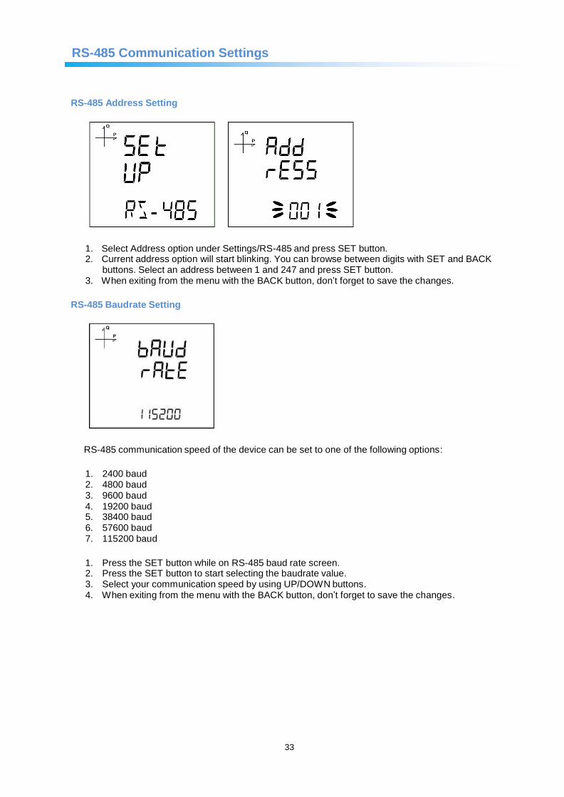
RS-485 Address Setting
1. Select Address option under Settings/RS-485 and press SET button. 2. Current address option will start blinking. You can browse between digits with SET and BACK
buttons. Select an address between 1 and 247 and press SET button. 3. When exiting from the menu with the BACK button, don’t forget to save the changes.
RS-485 Baudrate Setting
RS-485 communication speed of the device can be set to one of the following options:
1. 2400 baud 2. 4800 baud 3. 9600 baud 4. 19200 baud 5. 38400 baud 6. 57600 baud 7. 115200 baud
1. Press the SET button while on RS-485 baud rate screen. 2. Press the SET button to start selecting the baudrate value. 3. Select your communication speed by using UP/DOWN buttons. 4. When exiting from the menu with the BACK button, don’t forget to save the changes.
34
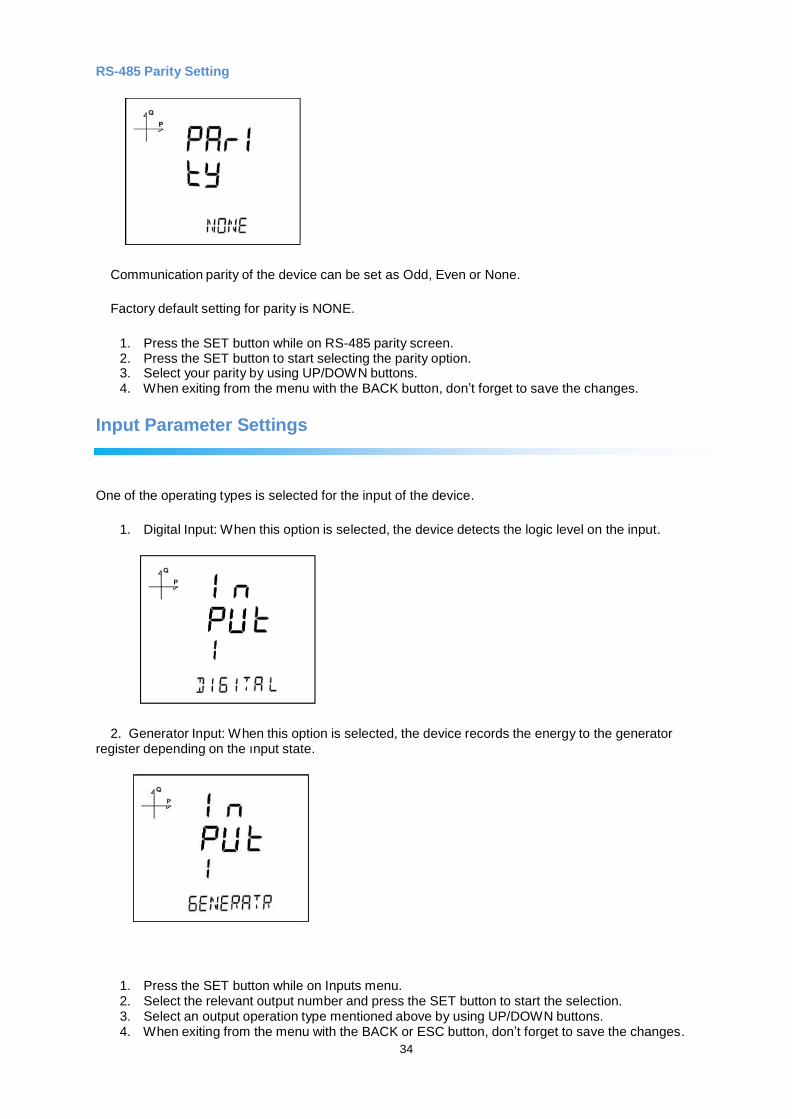
RS-485 Parity Setting
Communication parity of the device can be set as Odd, Even or None.
Factory default setting for parity is NONE.
1. Press the SET button while on RS-485 parity screen. 2. Press the SET button to start selecting the parity option. 3. Select your parity by using UP/DOWN buttons. 4. When exiting from the menu with the BACK button, don’t forget to save the changes.
Input Parameter Settings
One of the operating types is selected for the input of the device.
1. Digital Input: When this option is selected, the device detects the logic level on the input.
2. Generator Input: When this option is selected, the device records the energy to the generator
register depending on the ınput state.
1. Press the SET button while on Inputs menu. 2. Select the relevant output number and press the SET button to start the selection. 3. Select an output operation type mentioned above by using UP/DOWN buttons. 4. When exiting from the menu with the BACK or ESC button, don’t forget to save the changes.
35
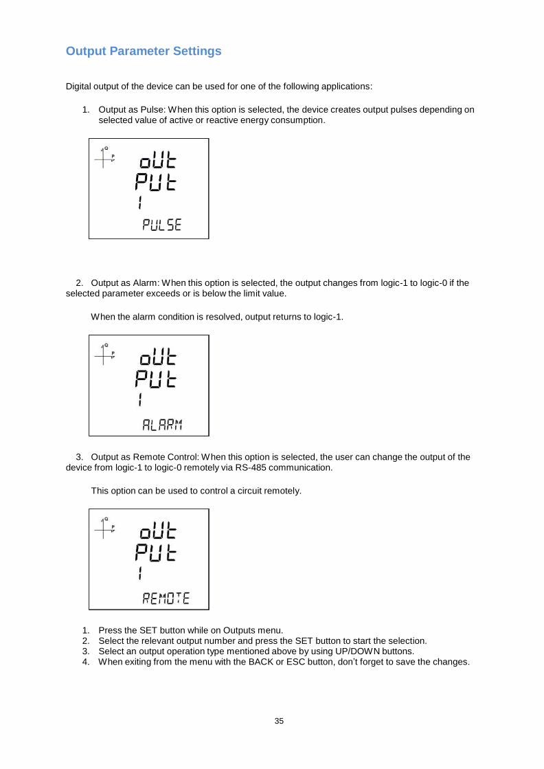
Output Parameter Settings
Digital output of the device can be used for one of the following applications:
1. Output as Pulse: When this option is selected, the device creates output pulses depending on
selected value of active or reactive energy consumption.
2. Output as Alarm: When this option is selected, the output changes from logic-1 to logic-0 if the
selected parameter exceeds or is below the limit value.
When the alarm condition is resolved, output returns to logic-1.
3. Output as Remote Control: When this option is selected, the user can change the output of the
device from logic-1 to logic-0 remotely via RS-485 communication.
This option can be used to control a circuit remotely.
1. Press the SET button while on Outputs menu. 2. Select the relevant output number and press the SET button to start the selection. 3. Select an output operation type mentioned above by using UP/DOWN buttons. 4. When exiting from the menu with the BACK or ESC button, don’t forget to save the changes.
36
Pulse Output Settings
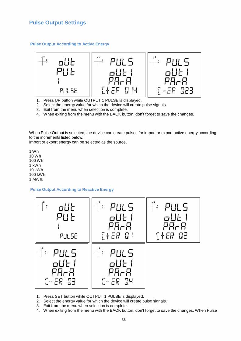
Pulse Output According to Active Energy
1. Press UP button while OUTPUT 1 PULSE is displayed. 2. Select the energy value for which the device will create pulse signals. 3. Exit from the menu when selection is complete. 4. When exiting from the menu with the BACK button, don’t forget to save the changes.
When Pulse Output is selected, the device can create pulses for import or export active energy according to the increments listed below. Import or export energy can be selected as the source.
1 Wh 10 Wh 100 Wh 1 kWh 10 kWh 100 kWh 1 MWh.
Pulse Output According to Reactive Energy
1. Press SET button while OUTPUT 1 PULSE is displayed. 2. Select the energy value for which the device will create pulse signals. 3. Exit from the menu when selection is complete. 4. When exiting from the menu with the BACK button, don’t forget to save the changes. When Pulse
37
Output is selected, the device can create pulses for import or export reactive energy according to the increments listed below.
Reactive energy values from Q1, Q2, Q3 and Q4 quadrants can be used as source.
1 VArh 10 VArh 100 VArh 1 kVArh 10 kVArh 100 kVArh. 1 MVArh
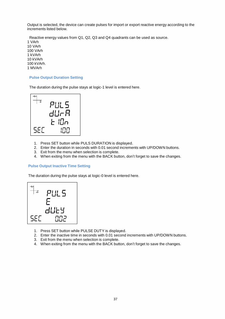
Pulse Output Duration Setting
The duration during the pulse stays at logic-1 level is entered here.
1. Press SET button while PULS DURATION is displayed. 2. Enter the duration in seconds with 0.01 second increments with UP/DOWN buttons. 3. Exit from the menu when selection is complete. 4. When exiting from the menu with the BACK button, don’t forget to save the changes.
Pulse Output Inactive Time Setting
The duration during the pulse stays at logic-0 level is entered here.
1. Press SET button while PULSE DUTY is displayed. 2. Enter the inactive time in seconds with 0.01 second increments with UP/DOWN buttons. 3. Exit from the menu when selection is complete. 4. When exiting from the menu with the BACK button, don’t forget to save the changes.
38
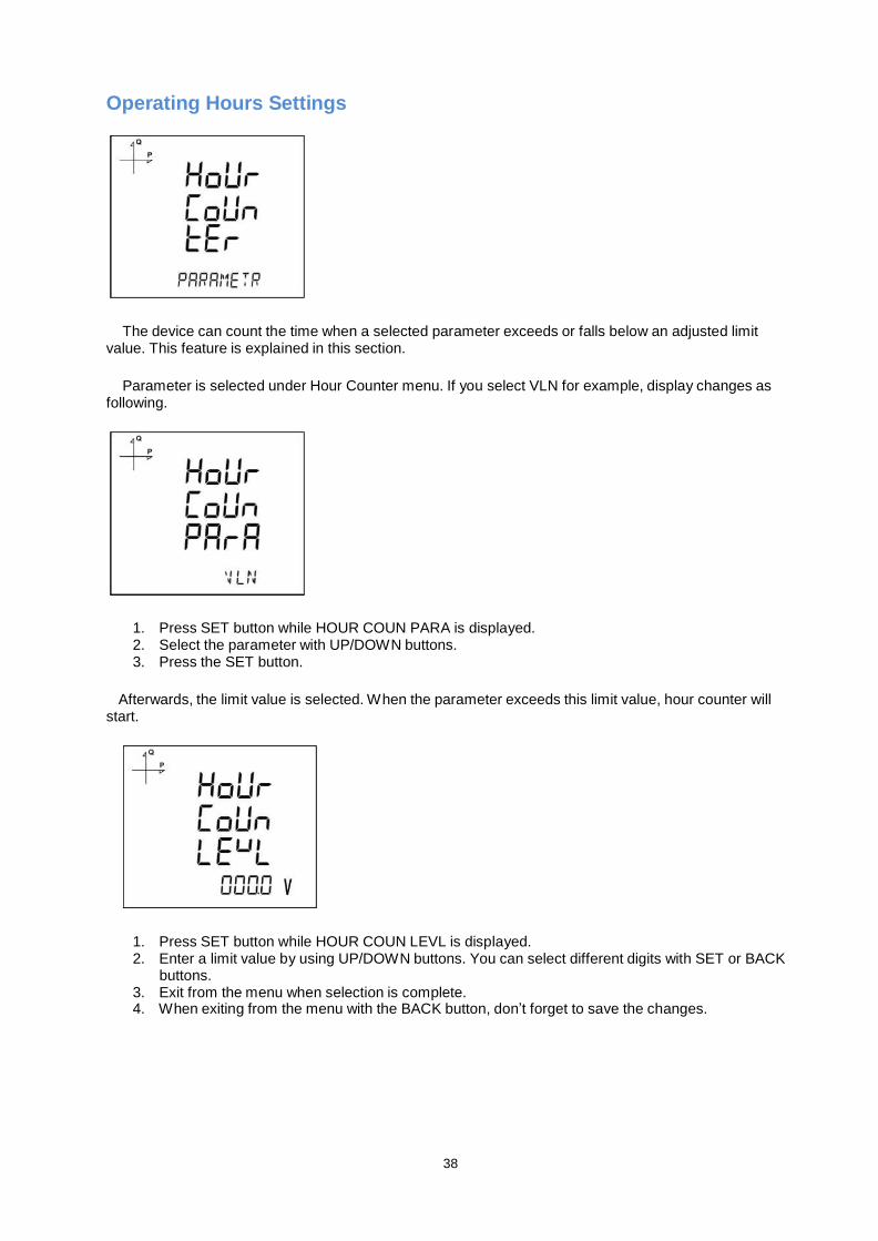
Operating Hours Settings
The device can count the time when a selected parameter exceeds or falls below an adjusted limit
value. This feature is explained in this section.
Parameter is selected under Hour Counter menu. If you select VLN for example, display changes as
following.
1. Press SET button while HOUR COUN PARA is displayed. 2. Select the parameter with UP/DOWN buttons. 3. Press the SET button.
Afterwards, the limit value is selected. When the parameter exceeds this limit value, hour counter will
start.
1. Press SET button while HOUR COUN LEVL is displayed. 2. Enter a limit value by using UP/DOWN buttons. You can select different digits with SET or BACK
buttons. 3. Exit from the menu when selection is complete. 4. When exiting from the menu with the BACK button, don’t forget to save the changes.
39
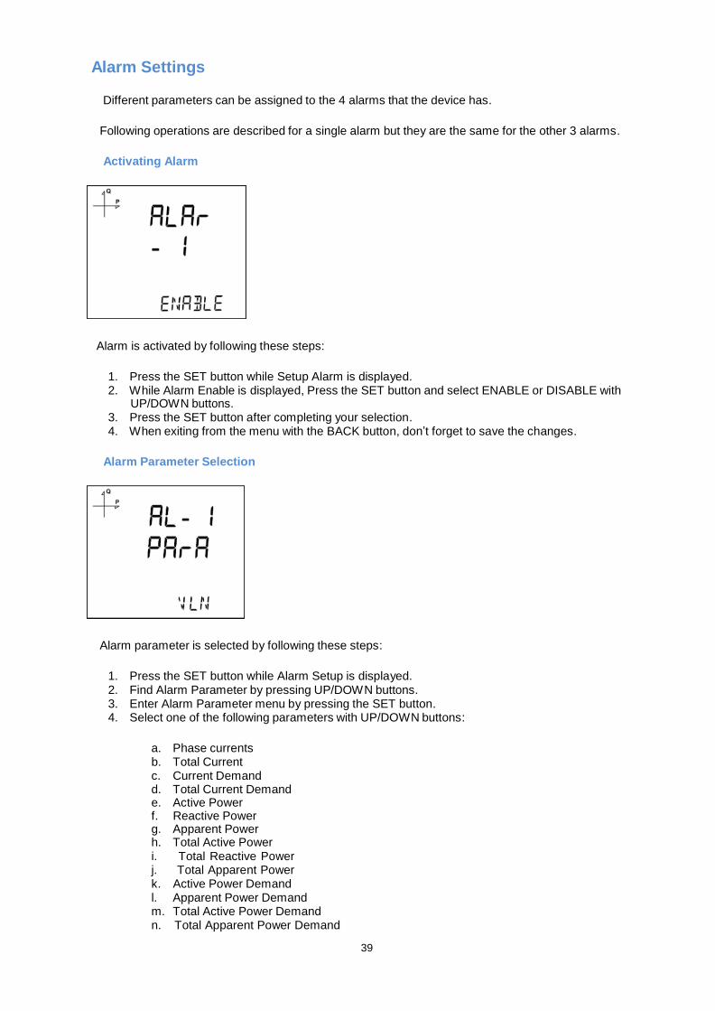
Alarm Settings
Different parameters can be assigned to the 4 alarms that the device has.
Following operations are described for a single alarm but they are the same for the other 3 alarms.
Activating Alarm
Alarm is activated by following these steps:
1. Press the SET button while Setup Alarm is displayed. 2. While Alarm Enable is displayed, Press the SET button and select ENABLE or DISABLE with
UP/DOWN buttons. 3. Press the SET button after completing your selection. 4. When exiting from the menu with the BACK button, don’t forget to save the changes.
Alarm Parameter Selection
Alarm parameter is selected by following these steps:
1. Press the SET button while Alarm Setup is displayed. 2. Find Alarm Parameter by pressing UP/DOWN buttons. 3. Enter Alarm Parameter menu by pressing the SET button. 4. Select one of the following parameters with UP/DOWN buttons:
a. Phase currents b. Total Current c. Current Demand d. Total Current Demand e. Active Power f. Reactive Power g. Apparent Power h. Total Active Power i. Total Reactive Power j. Total Apparent Power k. Active Power Demand l. Apparent Power Demand m. Total Active Power Demand n. Total Apparent Power Demand
40
o. Cos phi p. Total Cos phi q. Frequency r. THDV s. THDU t. THDI u. Hour Counter v. Digital Input w. Tariffs x. Phase-Neutral Voltage y. Phase-Phase Voltage
5. Press the SET button after completing your selection. You can start selecting the Alarm
Operation Type by pressing the UP button.
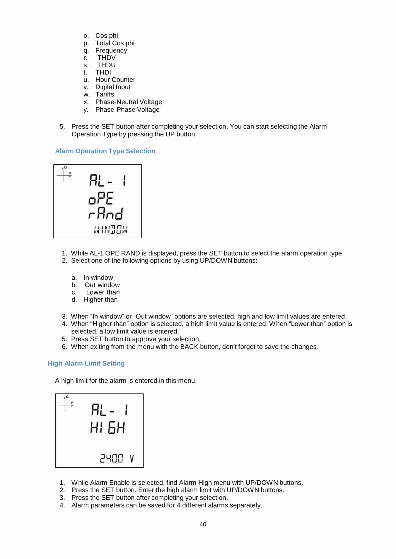
Alarm Operation Type Selection
1. While AL-1 OPE RAND is displayed, press the SET button to select the alarm operation type. 2. Select one of the following options by using UP/DOWN buttons:
a. In window b. Out window c. Lower than d. Higher than
3. When “In window” or “Out window” options are selected, high and low limit values are entered. 4. When “Higher than” option is selected, a high limit value is entered. When “Lower than” option is
selected, a low limit value is entered. 5. Press SET button to approve your selection. 6. When exiting from the menu with the BACK button, don’t forget to save the changes.
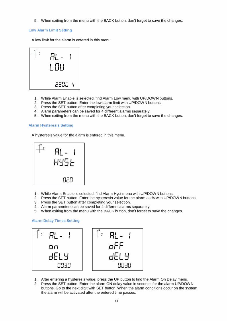
High Alarm Limit Setting
A high limit for the alarm is entered in this menu.
1. While Alarm Enable is selected, find Alarm High menu with UP/DOWN buttons. 2. Press the SET button. Enter the high alarm limit with UP/DOWN buttons. 3. Press the SET button after completing your selection. 4. Alarm parameters can be saved for 4 different alarms separately.
41
5. When exiting from the menu with the BACK button, don’t forget to save the changes.
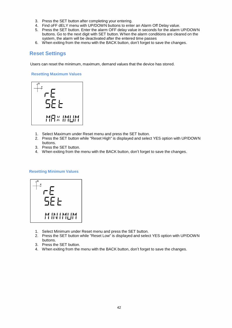
Low Alarm Limit Setting
A low limit for the alarm is entered in this menu.
1. While Alarm Enable is selected, find Alarm Low menu with UP/DOWN buttons. 2. Press the SET button. Enter the low alarm limit with UP/DOWN buttons. 3. Press the SET button after completing your selection. 4. Alarm parameters can be saved for 4 different alarms separately. 5. When exiting from the menu with the BACK button, don’t forget to save the changes.
Alarm Hysteresis Setting
A hysteresis value for the alarm is entered in this menu.
1. While Alarm Enable is selected, find Alarm Hyst menu with UP/DOWN buttons. 2. Press the SET button. Enter the hysteresis value for the alarm as % with UP/DOWN buttons. 3. Press the SET button after completing your selection. 4. Alarm parameters can be saved for 4 different alarms separately. 5. When exiting from the menu with the BACK button, don’t forget to save the changes.
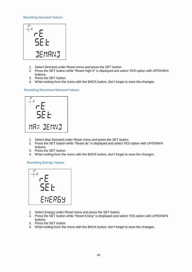
Alarm Delay Times Setting
1. After entering a hysteresis value, press the UP button to find the Alarm On Delay menu. 2. Press the SET button. Enter the alarm ON delay value in seconds for the alarm UP/DOWN
buttons. Go to the next digit with SET button. When the alarm conditions occur on the system, the alarm will be activated after the entered time passes.
42
3. Press the SET button after completing your entering. 4. Find oFF dELY menu with UP/DOWN buttons to enter an Alarm Off Delay value. 5. Press the SET button. Enter the alarm OFF delay value in seconds for the alarm UP/DOWN
buttons. Go to the next digit with SET button. When the alarm conditions are cleared on the system, the alarm will be deactivated after the entered time passes
6. When exiting from the menu with the BACK button, don’t forget to save the changes.
Reset Settings
Users can reset the minimum, maximum, demand values that the device has stored.
Resetting Maximum Values
1. Select Maximum under Reset menu and press the SET button. 2. Press the SET button while "Reset High" is displayed and select YES option with UP/DOWN
buttons. 3. Press the SET button. 4. When exiting from the menu with the BACK button, don’t forget to save the changes.
Resetting Minimum Values
1. Select Minimum under Reset menu and press the SET button. 2. Press the SET button while "Reset Low" is displayed and select YES option with UP/DOWN
buttons. 3. Press the SET button. 4. When exiting from the menu with the BACK button, don’t forget to save the changes.
43
Resetting Demand Values
1. Select Demand under Reset menu and press the SET button. 2. Press the SET button while "Reset High d" is displayed and select YES option with UP/DOWN
buttons. 3. Press the SET button. 4. When exiting from the menu with the BACK button, don’t forget to save the changes.
Resetting Maximum Demand Values
1. Select Max Demand under Reset menu and press the SET button. 2. Press the SET button while "Reset de" is displayed and select YES option with UP/DOWN
buttons. 3. Press the SET button. 4. When exiting from the menu with the BACK button, don’t forget to save the changes.
Resetting Energy Values
1. Select Energy under Reset menu and press the SET button. 2. Press the SET button while "Reset Energ" is displayed and select YES option with UP/DOWN
buttons. 3. Press the SET button. 4. When exiting from the menu with the BACK button, don’t forget to save the changes.
44
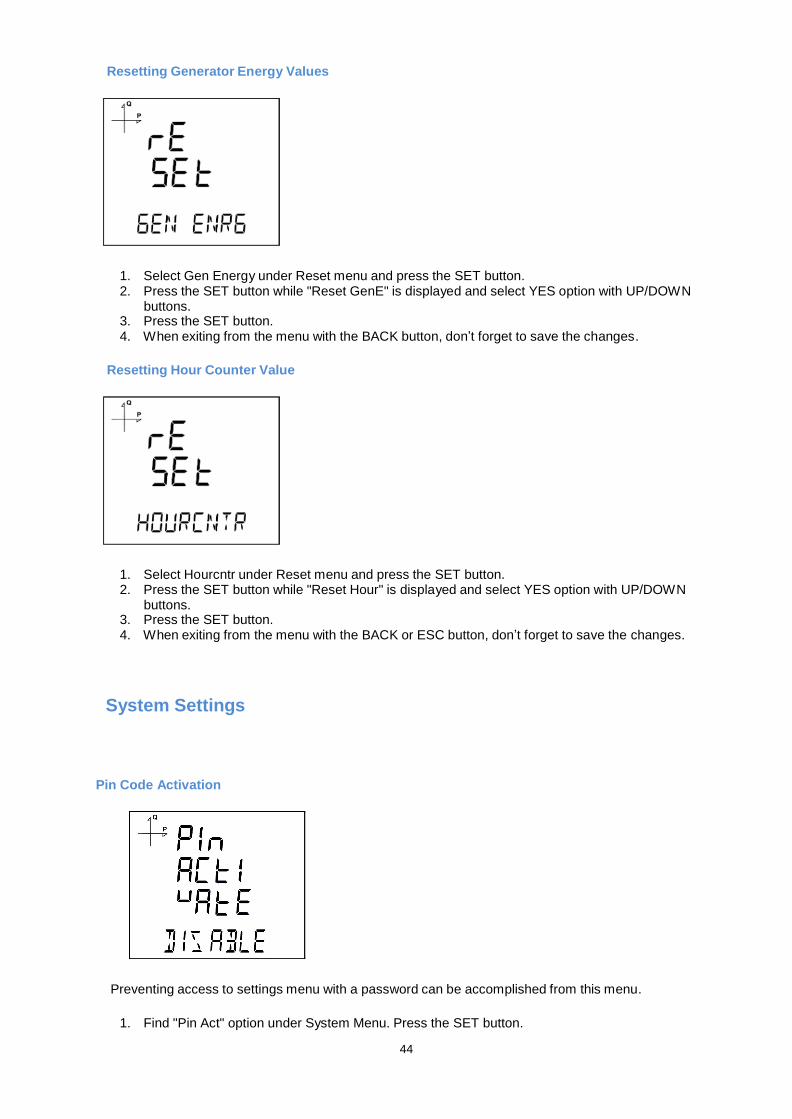
Resetting Generator Energy Values
1. Select Gen Energy under Reset menu and press the SET button. 2. Press the SET button while "Reset GenE" is displayed and select YES option with UP/DOWN
buttons. 3. Press the SET button. 4. When exiting from the menu with the BACK button, don’t forget to save the changes.
Resetting Hour Counter Value
1. Select Hourcntr under Reset menu and press the SET button. 2. Press the SET button while "Reset Hour" is displayed and select YES option with UP/DOWN
buttons. 3. Press the SET button. 4. When exiting from the menu with the BACK or ESC button, don’t forget to save the changes.
System Settings
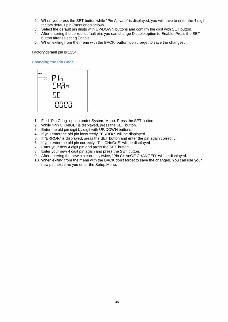
Pin Code Activation
Preventing access to settings menu with a password can be accomplished from this menu.
1. Find "Pin Act" option under System Menu. Press the SET button.
45
2. When you press the SET button while "Pin Acivate" is displayed, you will have to enter the 4 digit factory default pin (mentioned below).
3. Select the default pin digits with UP/DOWN buttons and confirm the digit with SET button. 4. After entering the correct default pin, you can change Disable option to Enable. Press the SET
button after selecting Enable. 5. When exiting from the menu with the BACK button, don’t forget to save the changes.
Factory default pin is 1234.
Changing the Pin Code
1. Find "Pin Chng" option under System Menu. Press the SET button. 2. While "Pin CHAnGE" is displayed, press the SET button. 3. Enter the old pin digit by digit with UP/DOWN buttons. 4. If you enter the old pin incorrectly, "ERROR" will be displayed. 5. If “ERROR” is displayed, press the SET button and enter the pin again correctly. 6. If you enter the old pin correctly, "Pin CHnGnE" will be displayed. 7. Enter your new 4 digit pin and press the SET button. 8. Enter your new 4 digit pin again and press the SET button. 9. After entering the new pin correctly twice, "Pin CHAnGE CHANGED" will be displayed. 10. When exiting from the menu with the BACK don’t forget to save the changes. You can use your
new pin next time you enter the Setup Menu.
46
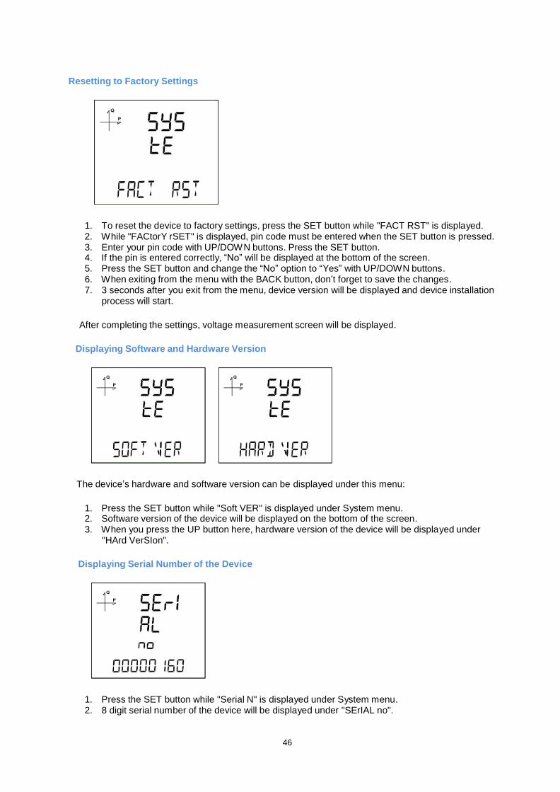
Resetting to Factory Settings
1. To reset the device to factory settings, press the SET button while "FACT RST" is displayed. 2. While "FACtorY rSET" is displayed, pin code must be entered when the SET button is pressed. 3. Enter your pin code with UP/DOWN buttons. Press the SET button. 4. If the pin is entered correctly, “No” will be displayed at the bottom of the screen. 5. Press the SET button and change the “No” option to “Yes” with UP/DOWN buttons. 6. When exiting from the menu with the BACK button, don’t forget to save the changes. 7. 3 seconds after you exit from the menu, device version will be displayed and device installation
process will start.
After completing the settings, voltage measurement screen will be displayed.
Displaying Software and Hardware Version
The device’s hardware and software version can be displayed under this menu:
1. Press the SET button while "Soft VER" is displayed under System menu. 2. Software version of the device will be displayed on the bottom of the screen. 3. When you press the UP button here, hardware version of the device will be displayed under
"HArd VerSIon".
Displaying Serial Number of the Device
1. Press the SET button while "Serial N" is displayed under System menu. 2. 8 digit serial number of the device will be displayed under "SErIAL no".
47
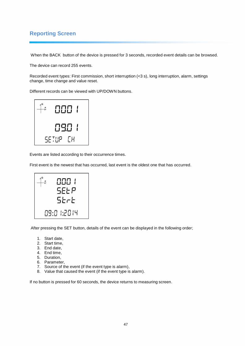
Reporting Screen
When the BACK button of the device is pressed for 3 seconds, recorded event details can be browsed.
The device can record 255 events.
Recorded event types: First commission, short interruption (<3 s), long interruption, alarm, settings change, time change and value reset.
Different records can be viewed with UP/DOWN buttons.
Events are listed according to their occurrence times.
First event is the newest that has occurred, last event is the oldest one that has occurred.
After pressing the SET button, details of the event can be displayed in the following order;
1. Start date, 2. Start time, 3. End date, 4. End time, 5. Duration, 6. Parameter, 7. Source of the event (if the event type is alarm), 8. Value that caused the event (if the event type is alarm).
If no button is pressed for 60 seconds, the device returns to measuring screen.

48
Reading the Records via Modbus
There are two options for accessing the records via Modbus:
Accessing the records according to time
For this method, the date of the record to be accessed is entered in UNIX time format to the Modbus addresses starting from 21000. There are 5 address fields. These addresses are for Load Profile, Voltage, Current, Power and THD in that order. The device finds the record closest to the entered date and writes the index belonging to this record to the related index registers.
When the user writes this index to the index register at the bottom of the tables at register addresses 23000, 24000, 25000 etc., the details of the entered register will be accessible on the same tables.
A free software is available to read the log values that are stored on the device. It can be downloaded from the following link:
http://www.entes.com.tr/dosyalar/Applications/Mpr3x4xLogReader/publish.htm
Accessing the records according to index
For this method, the user writes the record index number to the index register at the bottom of the tables at register addresses 23000, 24000, 25000 etc., the details of the entered register will be accessible on the same tables.
49
TECHNICAL FEATURES AND APPENDIX
Technical Features
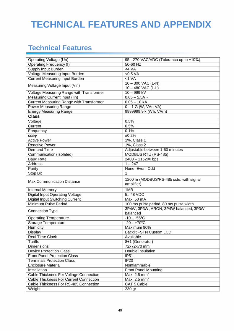
Operating Voltage (Un) 95 - 270 VAC/VDC (Tolerance up to ±10%)
Operating Frequency (f) 50-60 Hz
Supply Input Burden <4 VA
Voltage Measuring Input Burden <0.5 VA
Current Measuring Input Burden <1 VA
Measuring Voltage Input (Vin) 10 – 300 VAC (L-N) 10 – 480 VAC (L-L)
Voltage Measuring Range with Transformer 10 – 999 kV
Measuring Current Input (Iin) 0.05 – 5.5A ~
Current Measuring Range with Transformer 0.05 – 10 kA
Power Measuring Range 0 – 1 G (W, VAr, VA)
Energy Measuring Range 9999999.9 k (Wh, VArh)
Class
Voltage 0.5%
Current 0.5%
Frequency 0.1%
cosφ ±0.2%
Active Power 1%, Class 1
Reactive Power 1%, Class 2
Demand Time Adjustable between 1-60 minutes
Communication (Isolated) MODBUS RTU (RS-485)
Baud Rate 2400 – 115200 bps
Address 1 – 247
Parity None, Even, Odd
Stop Bit 1
Max Communication Distance 1200 m (MODBUS/RS-485 side, with signal amplifier)
Internal Memory 1MB
Digital Input Operating Voltage 5...48 VDC
Digital Input Switching Current Max. 50 mA
Minimum Pulse Period 100 ms pulse period, 80 ms pulse width
Connection Type 3P4W, 3P3W, ARON, 3P4W balanced, 3P3W balanced
Operating Temperature -10...+55ºC
Storage Temperature -20…+70ºC
Humidity Maximum 90%
Display Backlit FSTN Custom LCD
Real Time Clock Available
Tariffs 8+1 (Generator)
Dimensions 72x72x70 mm
Device Protection Class Double Insulation
Front Panel Protection Class IP51
Terminals Protection Class IP20
Enclosure Material Nonflammable
Installation Front Panel Mounting
Cable Thickness For Voltage Connection Max. 2.5 mm2
Cable Thickness For Current Connection Max. 2.5 mm2
Cable Thickness For RS-485 Connection CAT 5 Cable
Weight 230 gr
50
Applicable Standards
IEC 61557-12
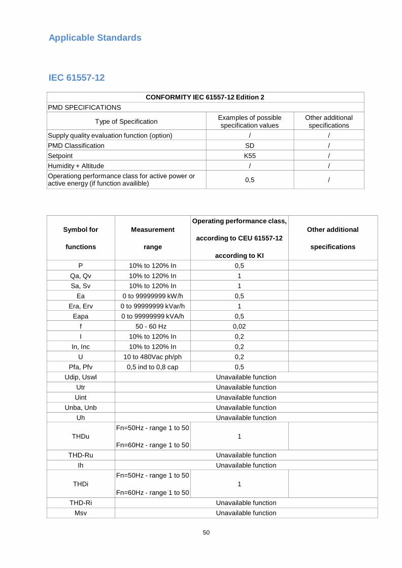
CONFORMITY IEC 61557-12 Edition 2
PMD SPECIFICATIONS
Type of Specification Examples of possible specification values
Other additional specifications
Supply quality evaluation function (option) / /
PMD Classification SD /
Setpoint K55 /
Humidity + Altitude / /
Operationg performance class for active power or active energy (if function availible)
0,5
/
Symbol for
functions
Measurement
range
Operating performance class,
according to CEU 61557-12
according to KI
Other additional
specifications
P 10% to 120% In 0,5
Qa, Qv 10% to 120% In 1
Sa, Sv 10% to 120% In 1
Ea 0 to 99999999 kW/h 0,5
Era, Erv 0 to 99999999 kVar/h 1
Eapa 0 to 99999999 kVA/h 0,5
f 50 - 60 Hz 0,02
I 10% to 120% In 0,2
In, Inc 10% to 120% In 0,2
U 10 to 480Vac ph/ph 0,2
Pfa, Pfv 0,5 ind to 0,8 cap 0,5
Udip, Uswl Unavailable function
Utr Unavailable function
Uint Unavailable function
Unba, Unb Unavailable function
Uh Unavailable function
THDu
Fn=50Hz - range 1 to 50
Fn=60Hz - range 1 to 50
1
THD-Ru Unavailable function
Ih Unavailable function
THDi
Fn=50Hz - range 1 to 50
Fn=60Hz - range 1 to 50
1
THD-Ri Unavailable function
Msv Unavailable function
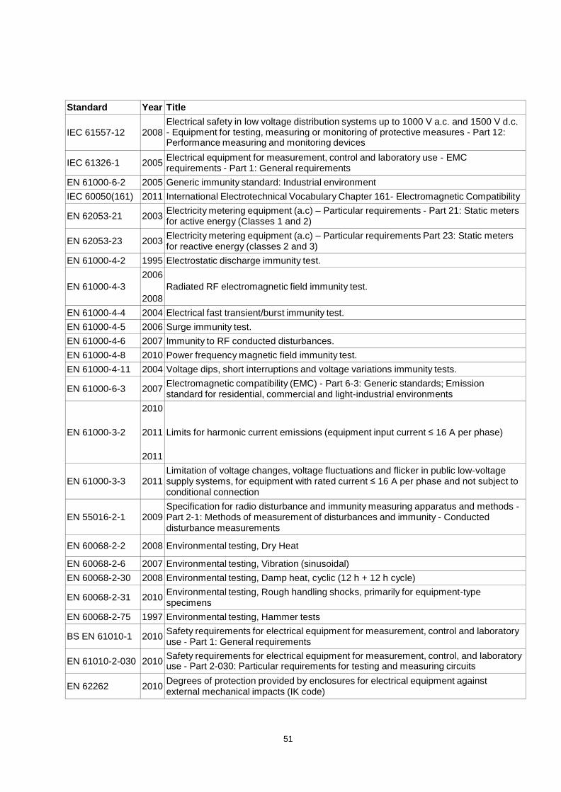
Standard Year Title
IEC 61557-12
2008
Electrical safety in low voltage distribution systems up to 1000 V a.c. and 1500 V d.c. - Equipment for testing, measuring or monitoring of protective measures - Part 12: Performance measuring and monitoring devices
IEC 61326-1
2005 Electrical equipment for measurement, control and laboratory use - EMC requirements - Part 1: General requirements
EN 61000-6-2 2005 Generic immunity standard: Industrial environment
IEC 60050(161) 2011 International Electrotechnical Vocabulary Chapter 161- Electromagnetic Compatibility
EN 62053-21
2003 Electricity metering equipment (a.c) – Particular requirements - Part 21: Static meters for active energy (Classes 1 and 2)
EN 62053-23
2003 Electricity metering equipment (a.c) – Particular requirements Part 23: Static meters for reactive energy (classes 2 and 3)
EN 61000-4-2 1995 Electrostatic discharge immunity test.
EN 61000-4-3
2006
2008
Radiated RF electromagnetic field immunity test.
EN 61000-4-4 2004 Electrical fast transient/burst immunity test.
EN 61000-4-5 2006 Surge immunity test.
EN 61000-4-6 2007 Immunity to RF conducted disturbances.
EN 61000-4-8 2010 Power frequency magnetic field immunity test.
EN 61000-4-11 2004 Voltage dips, short interruptions and voltage variations immunity tests.
EN 61000-6-3
2007 Electromagnetic compatibility (EMC) - Part 6-3: Generic standards; Emission standard for residential, commercial and light-industrial environments
EN 61000-3-2
2010
2011
2011
Limits for harmonic current emissions (equipment input current ≤ 16 A per phase)
EN 61000-3-3
2011
Limitation of voltage changes, voltage fluctuations and flicker in public low-voltage supply systems, for equipment with rated current ≤ 16 A per phase and not subject to conditional connection
EN 55016-2-1
2009
Specification for radio disturbance and immunity measuring apparatus and methods - Part 2-1: Methods of measurement of disturbances and immunity - Conducted disturbance measurements
EN 60068-2-2
2008
Environmental testing, Dry Heat
EN 60068-2-6 2007 Environmental testing, Vibration (sinusoidal)
EN 60068-2-30 2008 Environmental testing, Damp heat, cyclic (12 h + 12 h cycle)
EN 60068-2-31
2010 Environmental testing, Rough handling shocks, primarily for equipment-type specimens
EN 60068-2-75 1997 Environmental testing, Hammer tests
BS EN 61010-1
2010 Safety requirements for electrical equipment for measurement, control and laboratory use - Part 1: General requirements
EN 61010-2-030
2010 Safety requirements for electrical equipment for measurement, control, and laboratory use - Part 2-030: Particular requirements for testing and measuring circuits
EN 62262
2010 Degrees of protection provided by enclosures for electrical equipment against external mechanical impacts (IK code)
51


![TLE ANALYSER · TLE ANALYSER User Manual v2.8 TLE analysis ... TLE ANALYSER Version 2.8 - 2013 TLE ANALYSER - User Manual [4] 2. TLE Analyser Setup and Options TLE Updater allow to](https://img.pdfslide.us/doc/110x75/5aa68a5c7f8b9a517d8ea13c/tle-analyser-analyser-user-manual-v28-tle-analysis-tle-analyser-version-28.jpg)