Embed Size (px)
Citation preview
DKM-405 User Manual V-1.5
- 1 -
DKM-405 NETWORK
ANALYSER
WITH TOTAL HARMONIC
DISTORTION DISPLAY
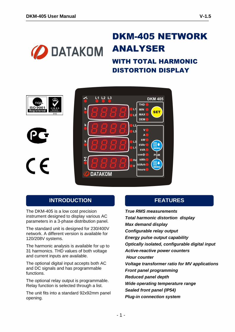
The DKM-405 is a low cost precision instrument designed to display various AC parameters in a 3-phase distribution panel.
The standard unit is designed for 230/400V network. A different version is available for 120/208V systems.
The harmonic analysis is available for up to 31 harmonics. THD values of both voltage and current inputs are available.
The optional digital input accepts both AC and DC signals and has programmable functions.
The optional relay output is programmable. Relay function is selected through a list.
The unit fits into a standard 92x92mm panel opening.
True RMS measurements
Total harmonic distortion display
Max demand display
Configurable relay output
Energy pulse output capability
Optically isolated, configurable digital input
Active-reactive power counters
Hour counter
Voltage transformer ratio for MV applications
Front panel programming
Reduced panel depth
Wide operating temperature range
Sealed front panel (IP54)
Plug-in connection system
FEATURES INTRODUCTION
DKM-405 User Manual V-1.5
- 2 -
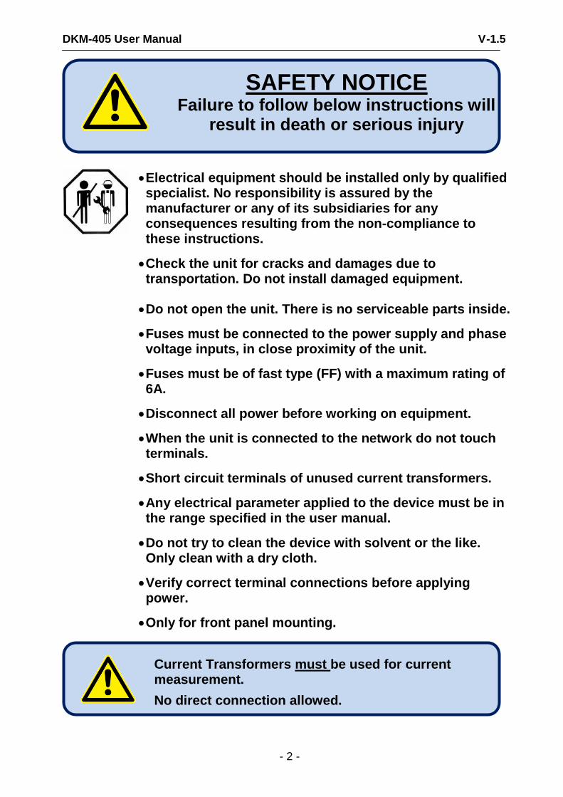
Electrical equipment should be installed only by qualified specialist. No responsibility is assured by the manufacturer or any of its subsidiaries for any consequences resulting from the non-compliance to these instructions.
Check the unit for cracks and damages due to transportation. Do not install damaged equipment.
Do not open the unit. There is no serviceable parts inside.
Fuses must be connected to the power supply and phase voltage inputs, in close proximity of the unit.
Fuses must be of fast type (FF) with a maximum rating of 6A.
Disconnect all power before working on equipment.
When the unit is connected to the network do not touch terminals.
Short circuit terminals of unused current transformers.
Any electrical parameter applied to the device must be in the range specified in the user manual.
Do not try to clean the device with solvent or the like. Only clean with a dry cloth.
Verify correct terminal connections before applying power.
Only for front panel mounting.
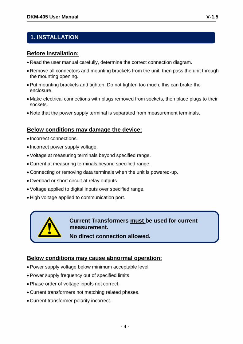
Current Transformers must be used for current measurement.
No direct connection allowed.
SAFETY NOTICE
Failure to follow below instructions will result in death or serious injury
DKM-405 User Manual V-1.5
- 3 -
Section 1. INSTALLATION
1.1. FRONT / REAR PANELS 1.2. MECHANICAL INSTALLATION 1.3. ELECTRICAL INSTALLATION 1.4. CONNECTION DIAGRAM
2. PUSHBUTTON FUNCTIONS 3. DISPLAY NAVIGATION 4. DEVICE CONFIGURATION
4.1. INTRODUCTION 4.2. RESETTING DEMAND VALUES 4.3. RESETTING ENERGY COUNTERS 4.4. RESETTING THE HOUR COUNTER 4.5. RESETTING ALARMS 4.6. SETTING THE DEFAULT SCREEN 4.7. SETTING THE CURRENT TRANSFORMER RATIO 4.8. SETTING THE VOLTAGE TRANSFORMER RATIO 4.9. SETTING HIGH AND LOW VOLTAGE LIMITS 4.10. SETTING HIGH AND LOW FREQUENCY LIMITS 4.11. SETTING THE OVERCURRENT LIMIT 4.12. SETTING HIGH AND LOW ACTIVE POWER LIMITS 4.13. SETTING HIGH AND LOW REACTIVE POWER LIMITS 4.14. SETTING HIGH AND LOW POWER FACTOR LIMITS 4.15. CONFIGURING THE DIGITAL INPUT 4.16. CONFIGURING THE RELAY OUTPUT 4.17. DISPLAYING THE FIRMWARE VERSION 4.18. CALIBRATION 4.19. LAMP TEST
5. TECHNICAL SPECIFICATIONS
TABLE OF CONTENTS
DKM-405 User Manual V-1.5
- 4 -
Before installation:
Read the user manual carefully, determine the correct connection diagram.
Remove all connectors and mounting brackets from the unit, then pass the unit through the mounting opening.
Put mounting brackets and tighten. Do not tighten too much, this can brake the enclosure.
Make electrical connections with plugs removed from sockets, then place plugs to their sockets.
Note that the power supply terminal is separated from measurement terminals.
Below conditions may damage the device:
Incorrect connections.
Incorrect power supply voltage.
Voltage at measuring terminals beyond specified range.
Current at measuring terminals beyond specified range.
Connecting or removing data terminals when the unit is powered-up.
Overload or short circuit at relay outputs
Voltage applied to digital inputs over specified range.
High voltage applied to communication port.
Below conditions may cause abnormal operation:
Power supply voltage below minimum acceptable level.
Power supply frequency out of specified limits
Phase order of voltage inputs not correct.
Current transformers not matching related phases.
Current transformer polarity incorrect.
Current Transformers must be used for current measurement.
No direct connection allowed.
1. INSTALLATION
DKM-405 User Manual V-1.5
- 5 -
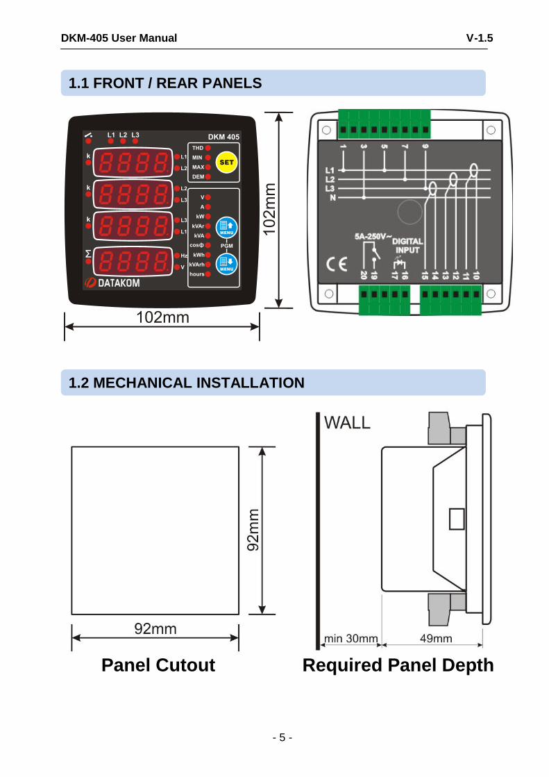
Panel Cutout Required Panel Depth
1.2 MECHANICAL INSTALLATION
1.1 FRONT / REAR PANELS
DKM-405 User Manual V-1.5
- 6 -
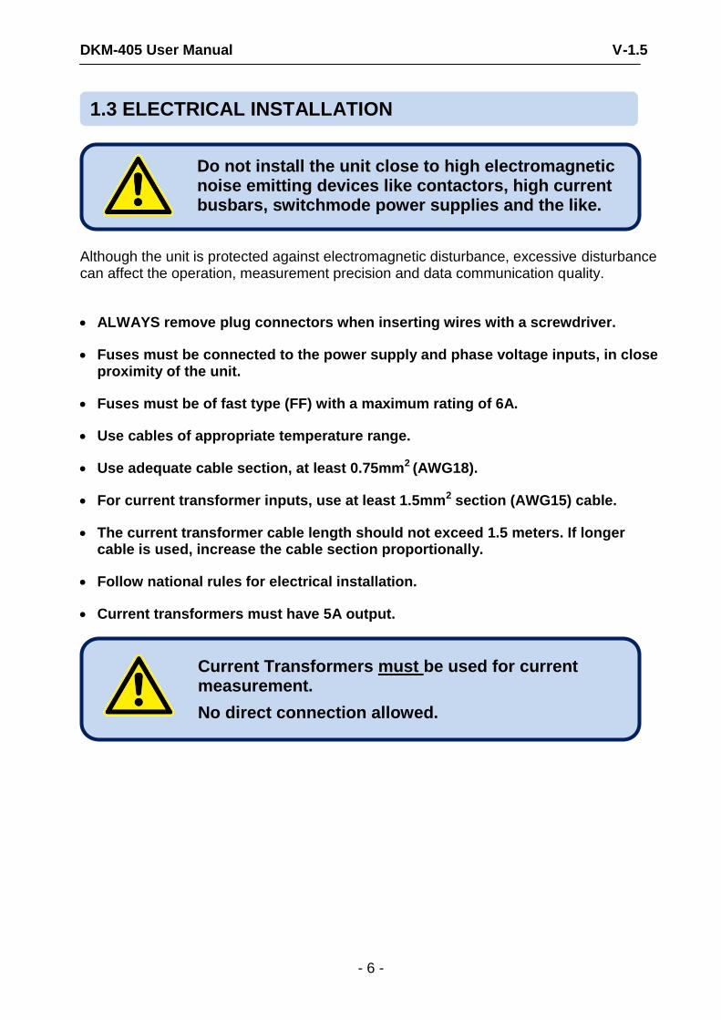
Although the unit is protected against electromagnetic disturbance, excessive disturbance can affect the operation, measurement precision and data communication quality.
ALWAYS remove plug connectors when inserting wires with a screwdriver.
Fuses must be connected to the power supply and phase voltage inputs, in close proximity of the unit.
Fuses must be of fast type (FF) with a maximum rating of 6A.
Use cables of appropriate temperature range.
Use adequate cable section, at least 0.75mm2 (AWG18).
For current transformer inputs, use at least 1.5mm2 section (AWG15) cable.
The current transformer cable length should not exceed 1.5 meters. If longer cable is used, increase the cable section proportionally.
Follow national rules for electrical installation.
Current transformers must have 5A output.
Current Transformers must be used for current measurement.
No direct connection allowed.
Do not install the unit close to high electromagnetic noise emitting devices like contactors, high current busbars, switchmode power supplies and the like.
1.3 ELECTRICAL INSTALLATION
DKM-405 User Manual V-1.5
- 7 -
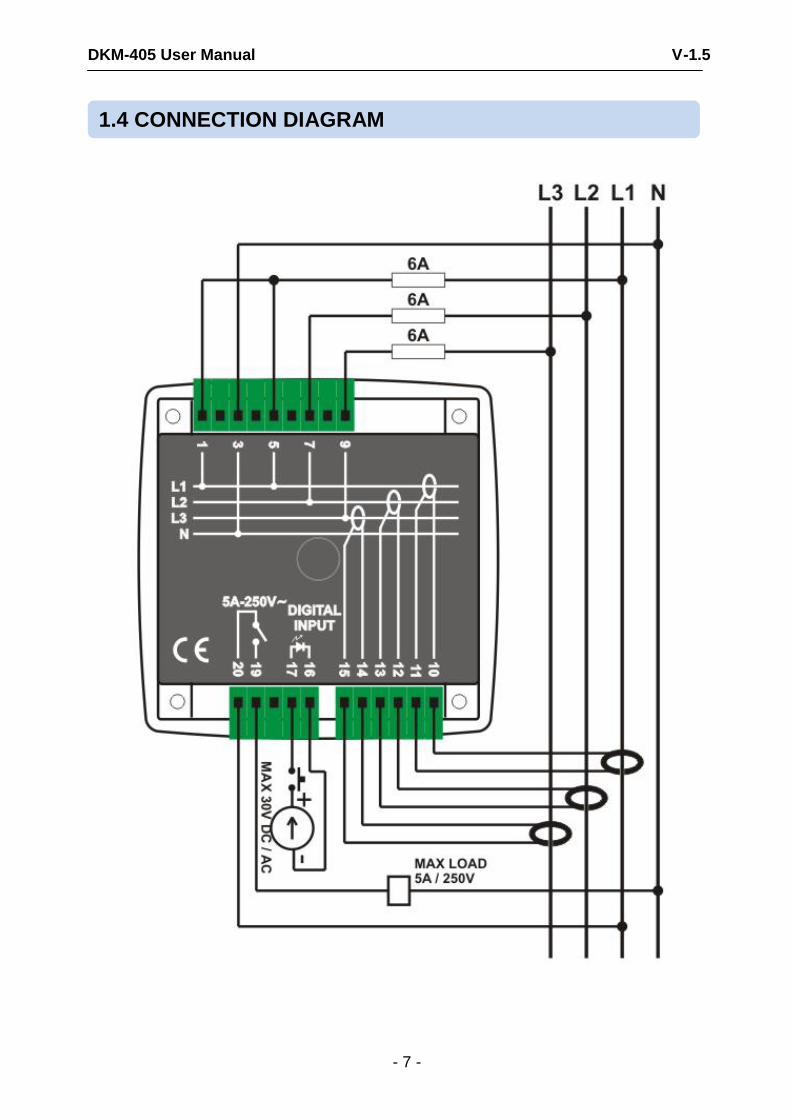
1.4 CONNECTION DIAGRAM

DKM-405 User Manual V-1.5
- 8 -
Three buttons on the front panel provide access to configuration and measurement screens.
BUTTON FUNCTION
Selects display context
THD display
Minimum values display
Maximum values display
Demand display
If all leds are off then actual measurements display.
HELD PRESSED FOR 5 SEC:
resets min-max values and displays minimum phase-to-neutral voltages.
Upper screen or Increase related value (configuration mode)
Lower screen or Decrease related value (configuration mode)
HELD PRESSED TOGETHER FOR 2 SEC:
Enters configuration mode.
IF NO BUTTON PRESSED FOR 5 MINUTES:
returns to the main display screen
2. PUSHBUTTON FUNCTIONS
DKM-405 User Manual V-1.5
- 9 -
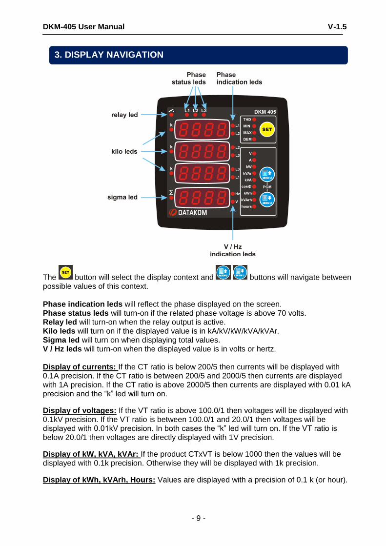
The button will select the display context and buttons will navigate between possible values of this context. Phase indication leds will reflect the phase displayed on the screen. Phase status leds will turn-on if the related phase voltage is above 70 volts. Relay led will turn-on when the relay output is active. Kilo leds will turn on if the displayed value is in kA/kV/kW/kVA/kVAr. Sigma led will turn on when displaying total values. V / Hz leds will turn-on when the displayed value is in volts or hertz. Display of currents: If the CT ratio is below 200/5 then currents will be displayed with 0.1A precision. If the CT ratio is between 200/5 and 2000/5 then currents are displayed with 1A precision. If the CT ratio is above 2000/5 then currents are displayed with 0.01 kA precision and the “k” led will turn on.
Display of voltages: If the VT ratio is above 100.0/1 then voltages will be displayed with 0.1kV precision. If the VT ratio is between 100.0/1 and 20.0/1 then voltages will be displayed with 0.01kV precision. In both cases the “k” led will turn on. If the VT ratio is below 20.0/1 then voltages are directly displayed with 1V precision.
Display of kW, kVA, kVAr: If the product CTxVT is below 1000 then the values will be displayed with 0.1k precision. Otherwise they will be displayed with 1k precision.
Display of kWh, kVArh, Hours: Values are displayed with a precision of 0.1 k (or hour).
3. DISPLAY NAVIGATION
DKM-405 User Manual V-1.5
- 10 -
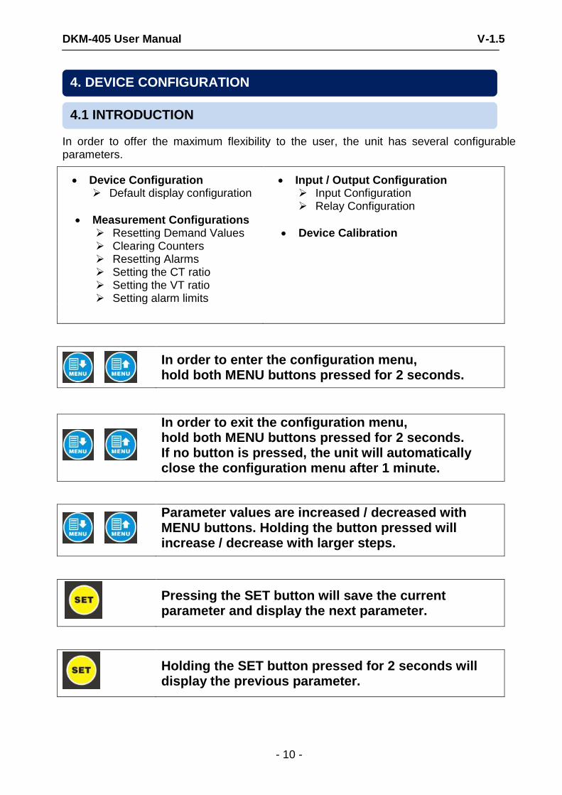
In order to offer the maximum flexibility to the user, the unit has several configurable parameters.
Device Configuration Default display configuration
Measurement Configurations Resetting Demand Values Clearing Counters Resetting Alarms Setting the CT ratio Setting the VT ratio Setting alarm limits
Input / Output Configuration Input Configuration Relay Configuration
Device Calibration
In order to enter the configuration menu, hold both MENU buttons pressed for 2 seconds.
In order to exit the configuration menu, hold both MENU buttons pressed for 2 seconds. If no button is pressed, the unit will automatically close the configuration menu after 1 minute.
Parameter values are increased / decreased with MENU buttons. Holding the button pressed will increase / decrease with larger steps.
Pressing the SET button will save the current parameter and display the next parameter.
Holding the SET button pressed for 2 seconds will display the previous parameter.
4.1 INTRODUCTION
4. DEVICE CONFIGURATION
DKM-405 User Manual V-1.5
- 11 -
SET
MENU
MENU
PGM
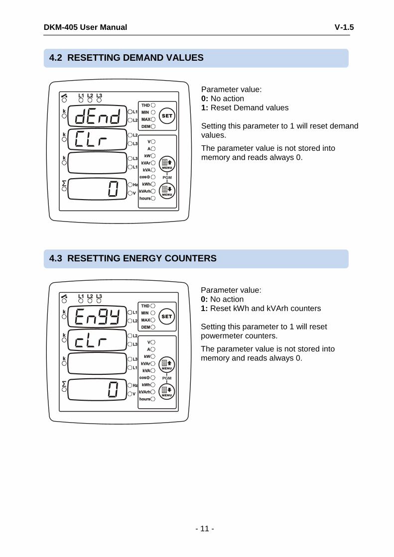
Parameter value: 0: No action 1: Reset Demand values Setting this parameter to 1 will reset demand values.
The parameter value is not stored into memory and reads always 0.
SET
MENU
MENU
PGM
Parameter value: 0: No action 1: Reset kWh and kVArh counters Setting this parameter to 1 will reset powermeter counters.
The parameter value is not stored into memory and reads always 0.
4.3 RESETTING ENERGY COUNTERS
4.2 RESETTING DEMAND VALUES
DKM-405 User Manual V-1.5
- 12 -
SET
MENU
MENU
PGM
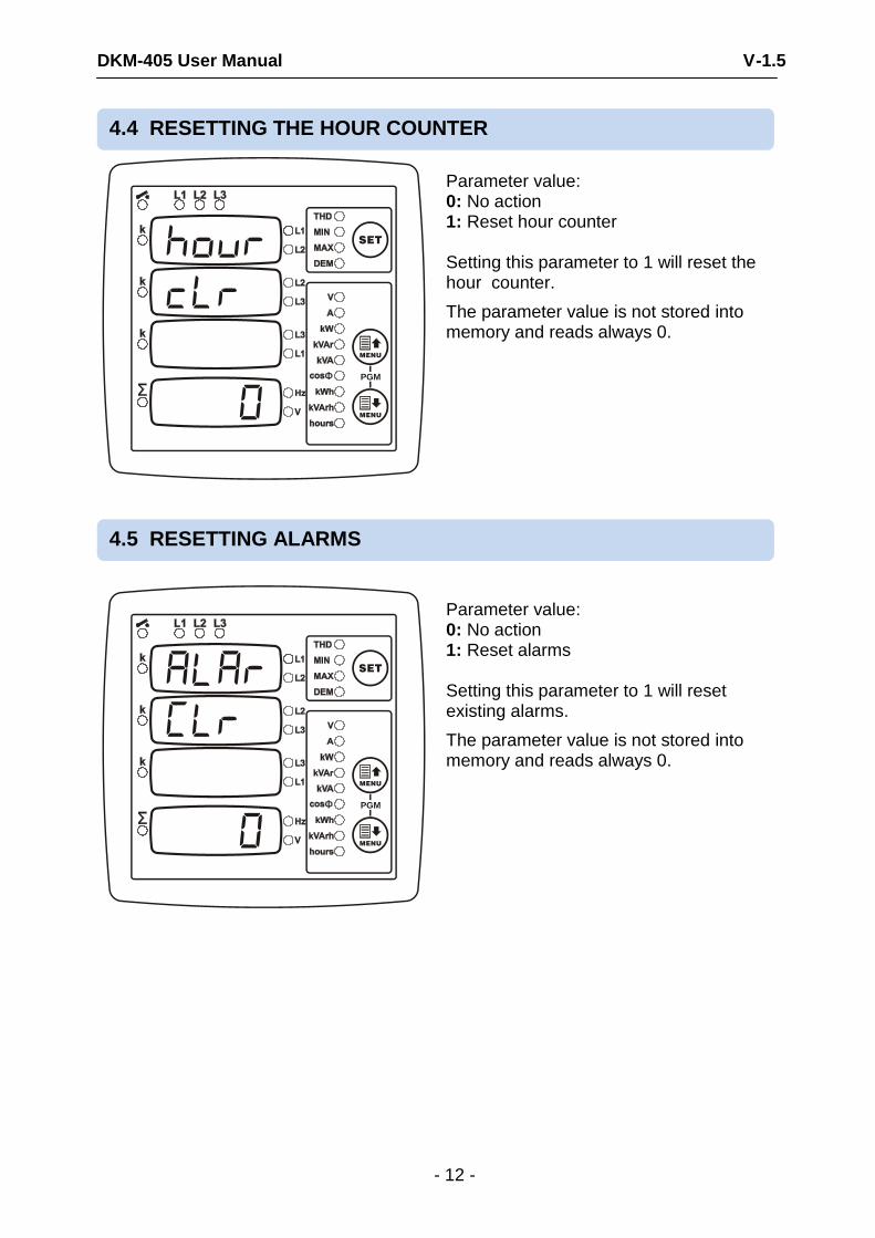
Parameter value: 0: No action 1: Reset hour counter Setting this parameter to 1 will reset the hour counter.
The parameter value is not stored into memory and reads always 0.
SET
MENU
MENU
PGM
Parameter value: 0: No action 1: Reset alarms Setting this parameter to 1 will reset existing alarms.
The parameter value is not stored into memory and reads always 0.
4.5 RESETTING ALARMS
4.4 RESETTING THE HOUR COUNTER

DKM-405 User Manual V-1.5
- 13 -
SET
MENU
MENU
PGM
This parameter selects the default screen that the unit returns 5 minutes after any key is pressed.
Setting this parameter to 0 will cancel the default screen.
Param. value
Upper displays
Lower display
0 no change no change
1 Voltages L-N Frequency
2 Voltages L-L Frequency
3 Voltages L-L Voltage L1-N
4 Currents Total current
5 Currents Frequency
6 Currents Voltage L1-N
7 Phase kW Total kW
8 Phase kW Frequency
9 Phase kW Voltage L1-N
10 Phase kVAr Total kVAr
11 Phase kVAr Frequency
12 Phase kVAr Voltage L1-N
13 Phase kVA Total kVA
14 Phase kVA Frequency
15 Phase kVA Voltage L1-N
16 Phase cosø Average cosø
17 Phase cosø Frequency
18 Phase cosø Voltage L1-N
19 - kWh counter
20 - kVArh counter
21 - hour counter
4.6 SETTING THE DEFAULT SCREEN
DKM-405 User Manual V-1.5
- 14 -
SET
MENU
MENU
PGM
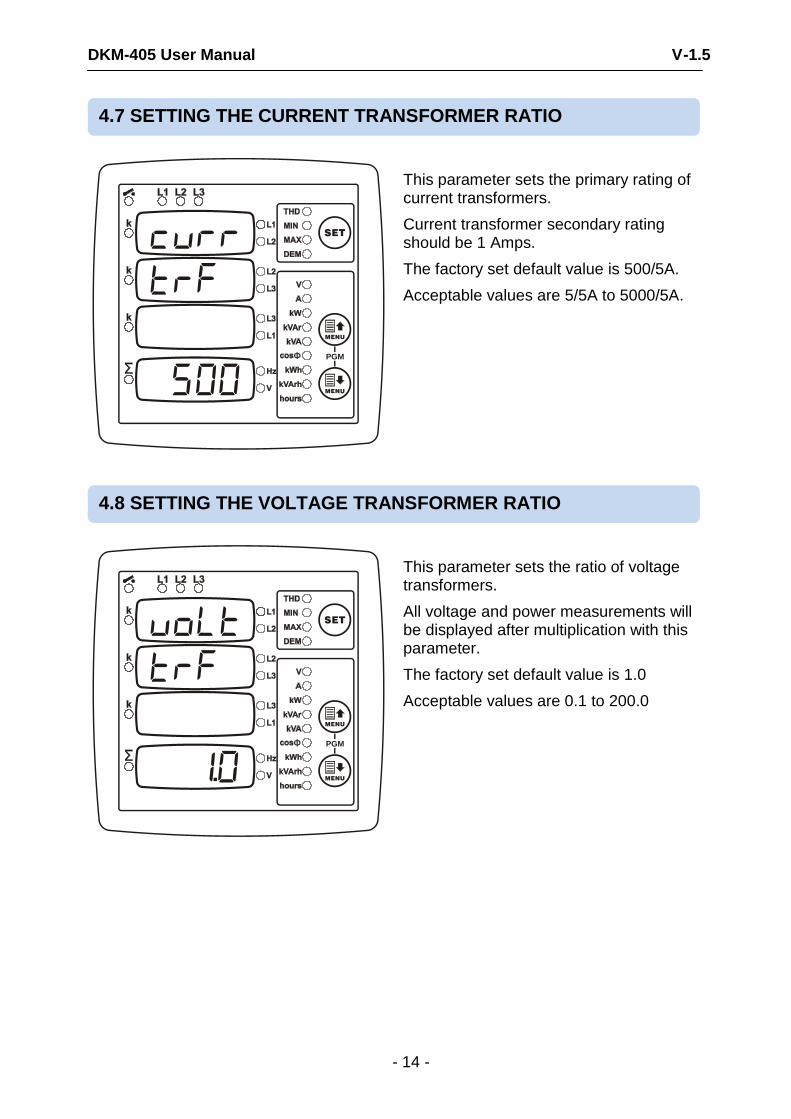
This parameter sets the primary rating of current transformers.
Current transformer secondary rating should be 1 Amps.
The factory set default value is 500/5A.
Acceptable values are 5/5A to 5000/5A.
SET
MENU
MENU
PGM
This parameter sets the ratio of voltage transformers.
All voltage and power measurements will be displayed after multiplication with this parameter.
The factory set default value is 1.0
Acceptable values are 0.1 to 200.0
4.8 SETTING THE VOLTAGE TRANSFORMER RATIO
4.7 SETTING THE CURRENT TRANSFORMER RATIO
DKM-405 User Manual V-1.5
- 15 -
SET
MENU
MENU
PGM
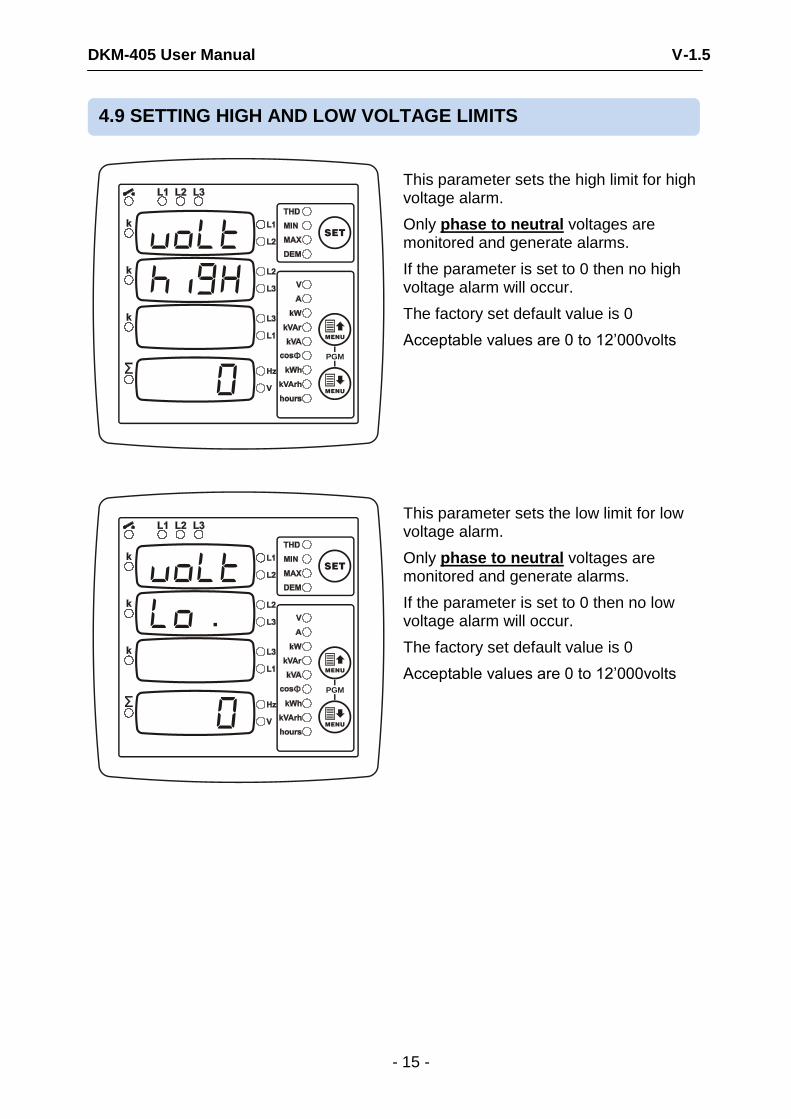
This parameter sets the high limit for high voltage alarm.
Only phase to neutral voltages are monitored and generate alarms.
If the parameter is set to 0 then no high voltage alarm will occur.
The factory set default value is 0
Acceptable values are 0 to 12’000volts
SET
MENU
MENU
PGM
This parameter sets the low limit for low voltage alarm.
Only phase to neutral voltages are monitored and generate alarms.
If the parameter is set to 0 then no low voltage alarm will occur.
The factory set default value is 0
Acceptable values are 0 to 12’000volts
4.9 SETTING HIGH AND LOW VOLTAGE LIMITS
DKM-405 User Manual V-1.5
- 16 -
SET
MENU
MENU
PGM
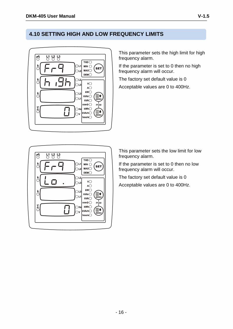
This parameter sets the high limit for high frequency alarm.
If the parameter is set to 0 then no high frequency alarm will occur.
The factory set default value is 0
Acceptable values are 0 to 400Hz.
SET
MENU
MENU
PGM
This parameter sets the low limit for low frequency alarm.
If the parameter is set to 0 then no low frequency alarm will occur.
The factory set default value is 0
Acceptable values are 0 to 400Hz.
4.10 SETTING HIGH AND LOW FREQUENCY LIMITS
DKM-405 User Manual V-1.5
- 17 -
SET
MENU
MENU
PGM
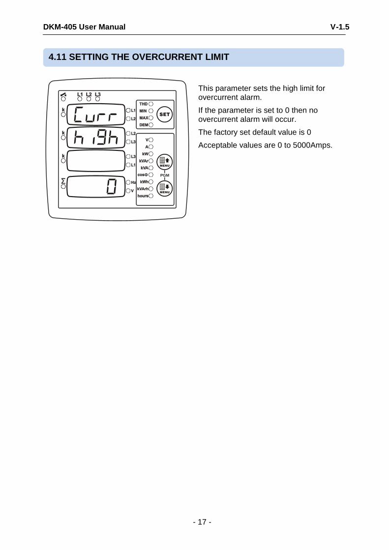
This parameter sets the high limit for overcurrent alarm.
If the parameter is set to 0 then no overcurrent alarm will occur.
The factory set default value is 0
Acceptable values are 0 to 5000Amps.
4.11 SETTING THE OVERCURRENT LIMIT
DKM-405 User Manual V-1.5
- 18 -
SET
MENU
MENU
PGM
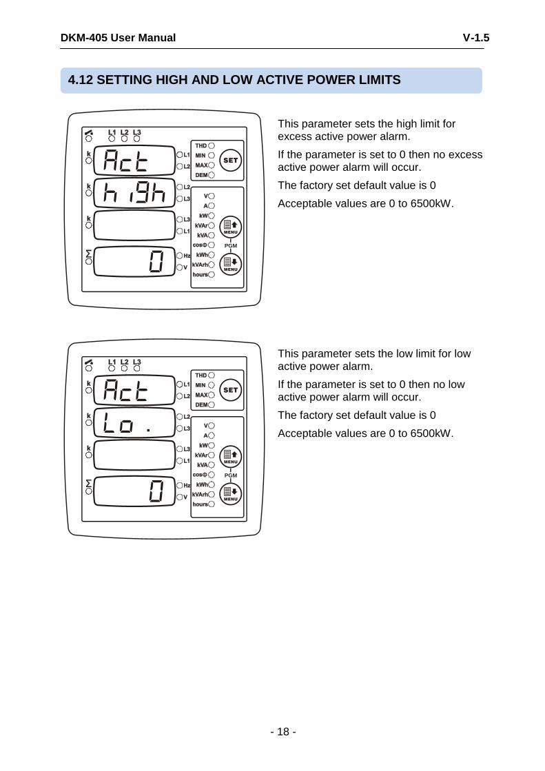
This parameter sets the high limit for excess active power alarm.
If the parameter is set to 0 then no excess active power alarm will occur.
The factory set default value is 0
Acceptable values are 0 to 6500kW.
SET
MENU
MENU
PGM
This parameter sets the low limit for low active power alarm.
If the parameter is set to 0 then no low active power alarm will occur.
The factory set default value is 0
Acceptable values are 0 to 6500kW.
4.12 SETTING HIGH AND LOW ACTIVE POWER LIMITS
DKM-405 User Manual V-1.5
- 19 -
SET
MENU
MENU
PGM
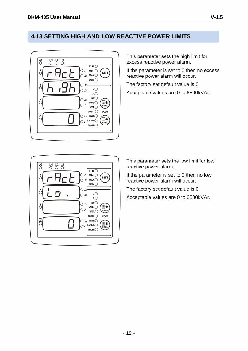
This parameter sets the high limit for excess reactive power alarm.
If the parameter is set to 0 then no excess reactive power alarm will occur.
The factory set default value is 0
Acceptable values are 0 to 6500kVAr.
SET
MENU
MENU
PGM
This parameter sets the low limit for low reactive power alarm.
If the parameter is set to 0 then no low reactive power alarm will occur.
The factory set default value is 0
Acceptable values are 0 to 6500kVAr.
4.13 SETTING HIGH AND LOW REACTIVE POWER LIMITS
DKM-405 User Manual V-1.5
- 20 -
SET
MENU
MENU
PGM
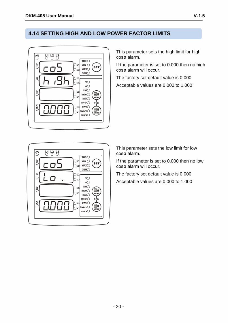
This parameter sets the high limit for high cosø alarm.
If the parameter is set to 0.000 then no high cosø alarm will occur.
The factory set default value is 0.000
Acceptable values are 0.000 to 1.000
SET
MENU
MENU
PGM
This parameter sets the low limit for low cosø alarm.
If the parameter is set to 0.000 then no low cosø alarm will occur.
The factory set default value is 0.000
Acceptable values are 0.000 to 1.000
4.14 SETTING HIGH AND LOW POWER FACTOR LIMITS
DKM-405 User Manual V-1.5
- 21 -
SET
MENU
MENU
PGM
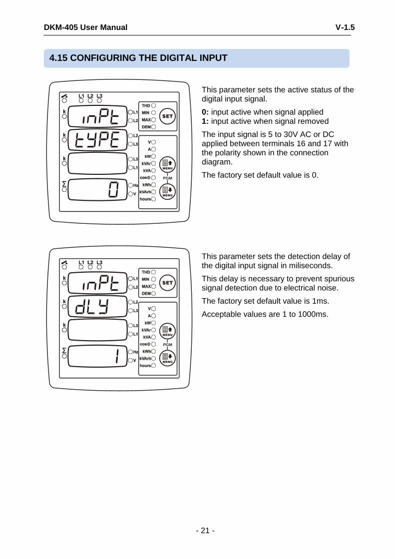
This parameter sets the active status of the digital input signal.
0: input active when signal applied 1: input active when signal removed
The input signal is 5 to 30V AC or DC applied between terminals 16 and 17 with the polarity shown in the connection diagram.
The factory set default value is 0.
SET
MENU
MENU
PGM
This parameter sets the detection delay of the digital input signal in miliseconds.
This delay is necessary to prevent spurious signal detection due to electrical noise.
The factory set default value is 1ms.
Acceptable values are 1 to 1000ms.
4.15 CONFIGURING THE DIGITAL INPUT
DKM-405 User Manual V-1.5
- 22 -
SET
MENU
MENU
PGM
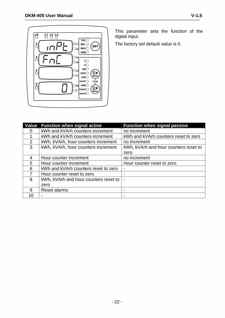
This parameter sets the function of the digital input.
The factory set default value is 0.
Value Function when signal active Function when signal passive
0 kWh and kVArh counters increment no increment
1 kWh and kVArh counters increment kWh and kVArh counters reset to zero
2 kWh, kVArh, hour counters increment no increment
3 kWh, kVArh, hour counters increment kWh, kVArh and hour counters reset to zero
4 Hour counter increment no increment
5 Hour counter increment Hour counter reset to zero
6 kWh and kVArh counters reset to zero -
7 Hour counter reset to zero -
8 kWh, kVArh and hour counters reset to zero
-
9 Reset alarms -
10 - -
DKM-405 User Manual V-1.5
- 23 -
SET
MENU
MENU
PGM
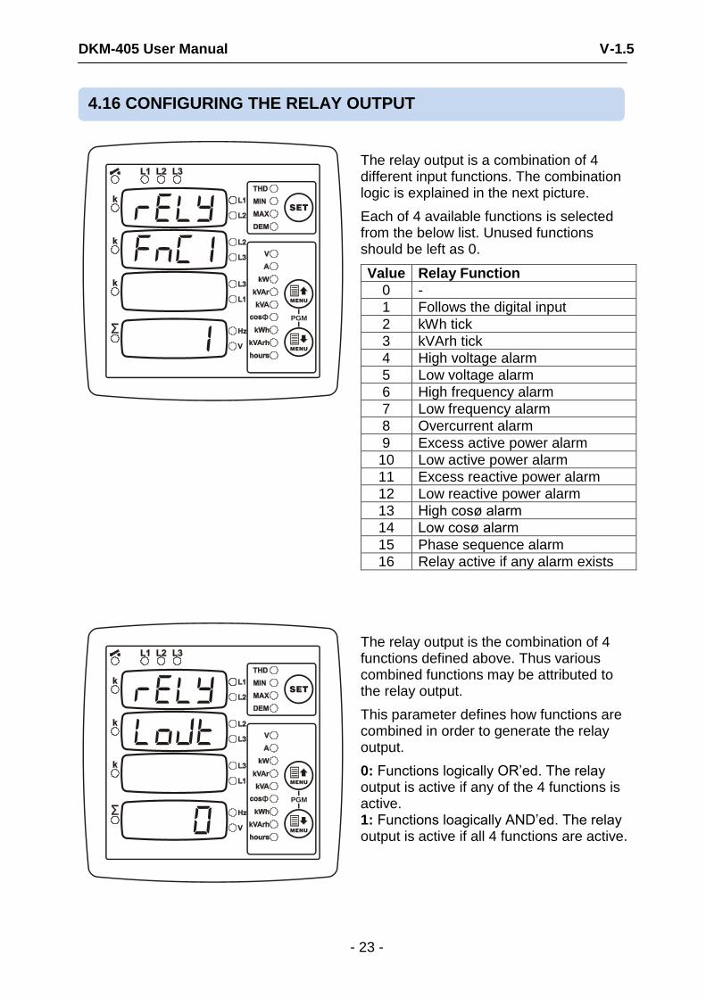
The relay output is a combination of 4 different input functions. The combination logic is explained in the next picture.
Each of 4 available functions is selected from the below list. Unused functions should be left as 0.
Value Relay Function
0 -
1 Follows the digital input
2 kWh tick
3 kVArh tick
4 High voltage alarm
5 Low voltage alarm
6 High frequency alarm
7 Low frequency alarm
8 Overcurrent alarm
9 Excess active power alarm
10 Low active power alarm
11 Excess reactive power alarm
12 Low reactive power alarm
13 High cosø alarm
14 Low cosø alarm
15 Phase sequence alarm
16 Relay active if any alarm exists
SET
MENU
MENU
PGM
The relay output is the combination of 4 functions defined above. Thus various combined functions may be attributed to the relay output.
This parameter defines how functions are combined in order to generate the relay output.
0: Functions logically OR’ed. The relay output is active if any of the 4 functions is active. 1: Functions loagically AND’ed. The relay output is active if all 4 functions are active.
4.16 CONFIGURING THE RELAY OUTPUT
DKM-405 User Manual V-1.5
- 24 -
SET
MENU
MENU
PGM
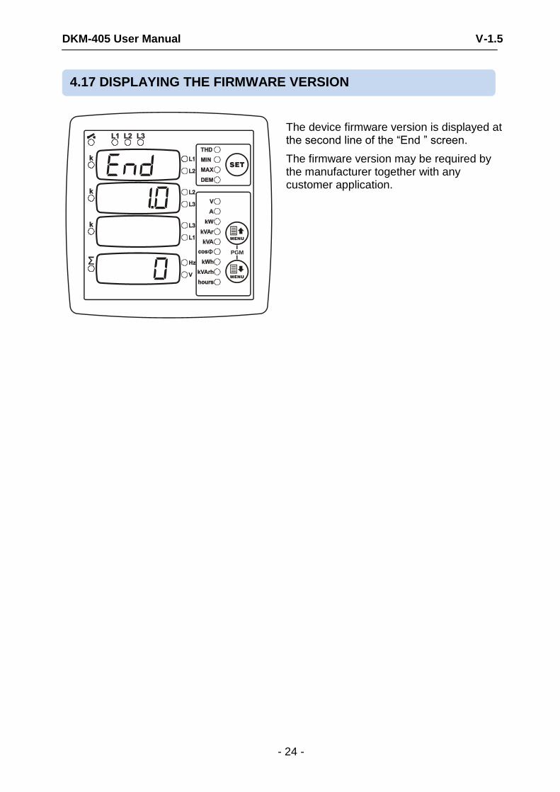
The device firmware version is displayed at the second line of the “End ” screen.
The firmware version may be required by the manufacturer together with any customer application.
4.17 DISPLAYING THE FIRMWARE VERSION
DKM-405 User Manual V-1.5
- 25 -
SET
MENU
MENU
PGM
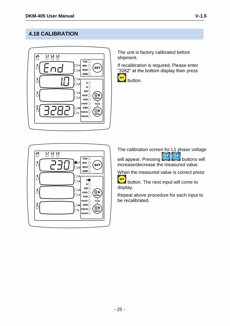
The unit is factory calibrated before shipment.
If recalibration is required, Please enter “3282” at the bottom display then press
button.
SET
MENU
MENU
PGM
The calibration screen for L1 phase voltage
will appear. Pressing buttons will increase/decrease the measured value.
When the measured value is correct press
button. The next input will come to display.
Repeat above procedure for each input to be recalibrated.
4.18 CALIBRATION
DKM-405 User Manual V-1.5
- 26 -
SET
MENU
MENU
PGM
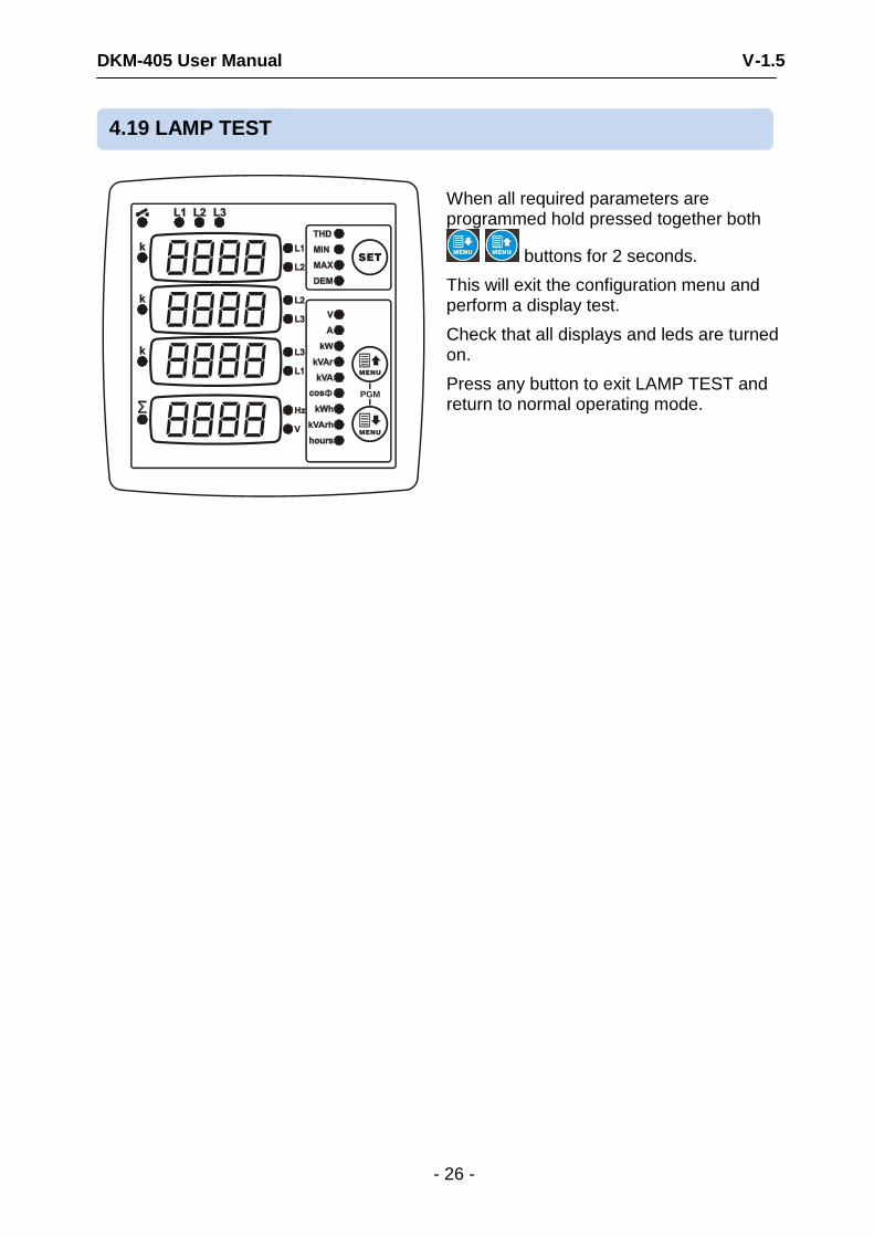
When all required parameters are programmed hold pressed together both
buttons for 2 seconds.
This will exit the configuration menu and perform a display test.
Check that all displays and leds are turned on.
Press any button to exit LAMP TEST and return to normal operating mode.
4.19 LAMP TEST
DKM-405 User Manual V-1.5
- 27 -
Power Supply Input: 170 - 275VAC, 50 - 60Hz nominal (± 10%) Different AC supply voltages available. Measurement Input Range:
Voltage inputs: 10 - 300 V AC (L-N) 20 - 520 V AC (L-L) Current inputs: 0.2 – 5.5 A AC Frequency: 30 - 100 Hz
Accuracy: Voltage: 0.5%+1digit Current: 0.5%+1 digit Frequency: 0.5%+1 digit Power(kW,kVAr): 1.0%+2digit Power factor: 2.0%+2digit Measurement Range:
CT range: 5/5A to 5000/5A
VT range: 0.1/1 to 200.0/1
kW range: 0.1 kW to 6.5 MW Power Consumption: < 4 VA Voltage burden: < 0.1VA per phase Current burden: < 1VA per phase Relay Outputs: 5A @ 250VAC Digital Inputs: Active level: 5 to 30V-DC or AC Min pulse duration: 250ms. Isolation: 1000V AC, 1 minute
Operating Temperature: -20°C to +80°C (-4 to +176 F). Maximum humidity: 95% non-condensing. Degree of Protection: IP 54 (Front Panel) , IP 30 (Back panel) Enclosure: Non-flammable, ROHS compliant, ABS/PC (UL94-V0) Installation: Flush mounting with rear retaining brackets Dimensions: 102x102x53mm (WxHxD) Panel Cutout: 92x92mm Weight: 200 gr
EU Directives Conformity: 2006/95/EC (low voltage) 2004/108/EC (EMC)
Norms of reference: EN 61010 (safety requirements) EN 61326 (EMC requirements)
PACKAGING INFORMATION
Pieces per Package: 12 pieces Package Size: 280 x 170 x 215mm (LxWxH) Package Weight: 2.6 kg
DATAKOM Electronics Ltd. Tel: +90-216-466 84 60 Fax: +90-216-364 65 65 e-mail: [email protected] http: www.datakom.com.tr
5. TECHNICAL SPECIFICATIONS