Embed Size (px)
Citation preview
Network Analyser Basics
Network Analyser Basics
Martin J. SiebersLab Manager
[email protected]://services.ee.sun.ac.za/wiki/index.php/High_Frequency_Lab
Network Analyser Basics
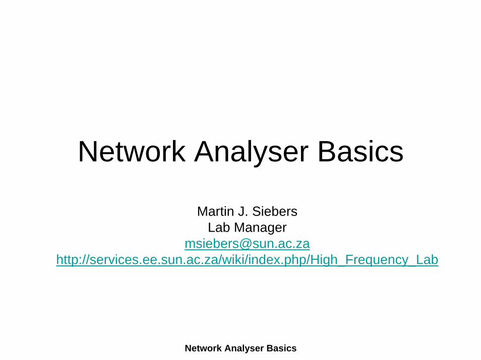
Overview• Network analysers fall into two categories
– The Vector Network Analyser (VNA) is capable of measuring complex reflection and transmission
– The scalar analyser can only measure magnitude • A VNA can measure S-parameter and VSWR,
loss, gain, isolation, and group delay of any two (or more) ports of a given network
• Key manufacturers of VNAs are Agilent (former HP), Anritsu (Wiltron), and Rohde & Schwarz.
• VNAs also called "ANA“ automated network analyser.
Network Analyser Basics
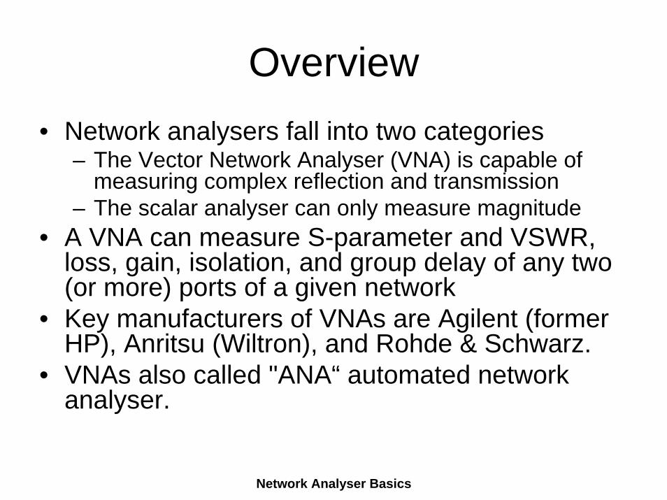
History• The original network analyser (HP 8409)
– No Error Correction build in– Error correction was done by hand
• Then the first automated network analysers were introduced.– A minicomputer processed the vector data– delivered error corrected and accurate magnitude and
phase of the four S-parameters• The next step was to build the error correction
into the TE and display the error-corrected measurements in nearly real time (the original HP 8510, circa 1982).
Network Analyser Basics
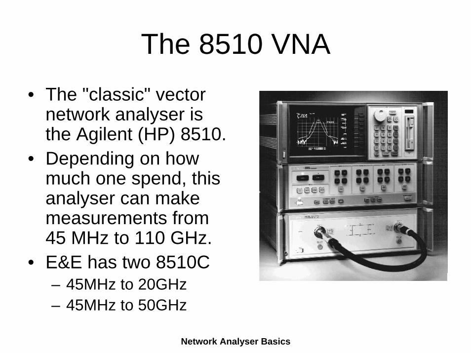
The 8510 VNA• The "classic" vector
network analyser is the Agilent (HP) 8510.
• Depending on how much one spend, this analyser can make measurements from 45 MHz to 110 GHz.
• E&E has two 8510C– 45MHz to 20GHz– 45MHz to 50GHz
Network Analyser Basics
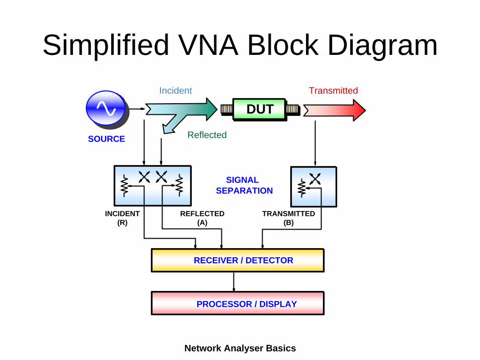
Simplified VNA Block Diagram
RECEIVER / DETECTOR
PROCESSOR / DISPLAY
REFLECTED(A)
TRANSMITTED(B)
INCIDENT (R)
SIGNALSEPARATION
Incident Transmitted
Reflected
DUT
SOURCE
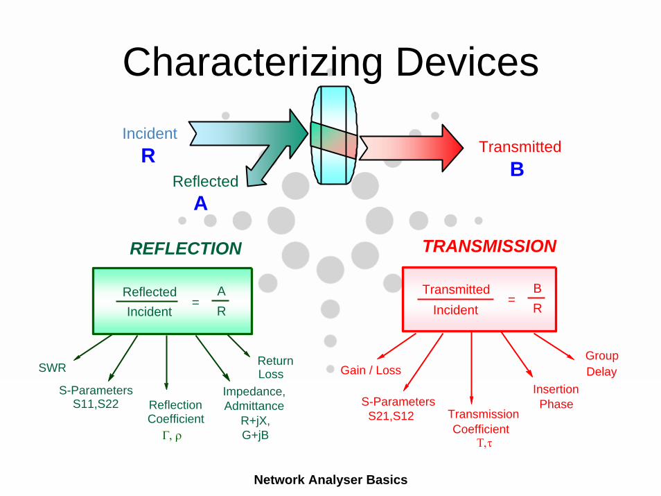
TransmittedIncident
TRANSMISSION
Gain / Loss
S-ParametersS21,S12
GroupDelay
Coefficient
Insertion Phase
ReflectedIncident
Transmission
REFLECTION
SWR
S-ParametersS11,S22 Reflection
Coefficient
Impedance, Admittance
R+jX, G+jB
ReturnLoss
Γ, ρΤ,τ
Incident
Reflected
TransmittedR BA
AR
=BR
=
Characterizing Devices
Network Analyser Basics
Network Analyser Basics
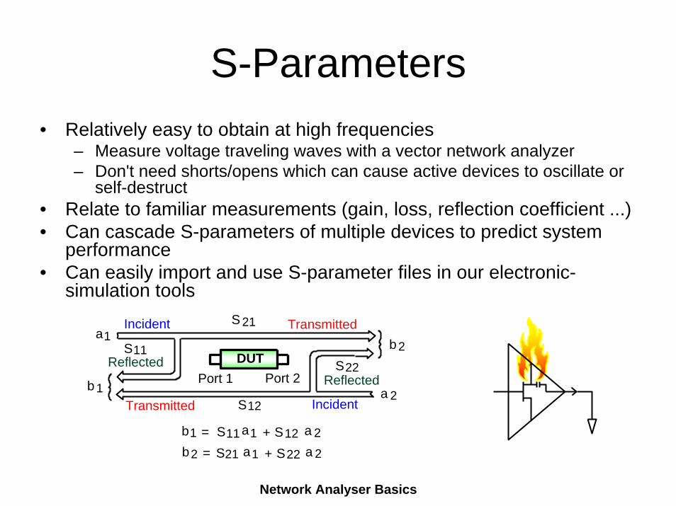
Incident TransmittedS 21
S11Reflected S22
Reflected
Transmitted Incidentb 1
a1 b2
a 2S12
DUT
b1 = S11 a1 + S12 a 2b2 = S21 a1 + S22 a 2
Port 1 Port 2
S-Parameters• Relatively easy to obtain at high frequencies
– Measure voltage traveling waves with a vector network analyzer– Don't need shorts/opens which can cause active devices to oscillate or
self-destruct• Relate to familiar measurements (gain, loss, reflection coefficient ...)• Can cascade S-parameters of multiple devices to predict system
performance• Can easily import and use S-parameter files in our electronic-
simulation tools
Network Analyser Basics
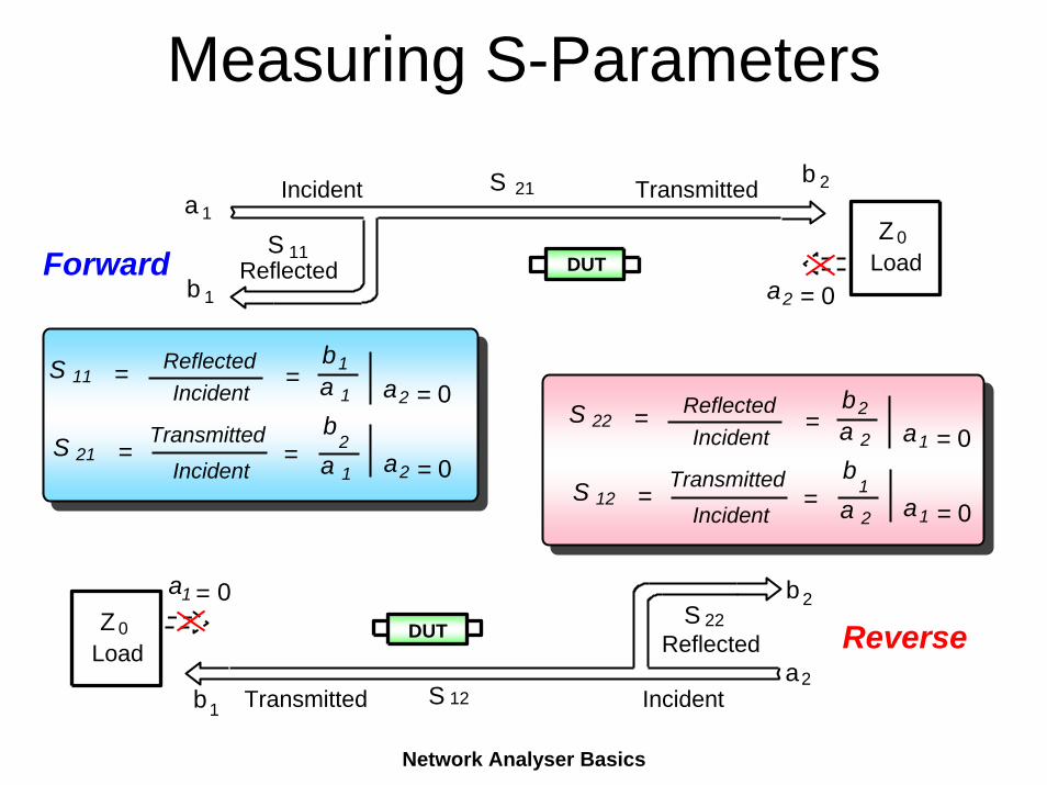
Measuring S-Parametersb
S 11 = ReflectedIncident
=b1a 1 a2 = 0
S 21 =Transmitted
Incident=
b2
a 1 a2 = 0
S 22 = ReflectedIncident
=b2a 2 a1 = 0
S 12 =Transmitted
Incident=
b1
a 2 a1 = 0
S 2Incident Transmitted21a
S 11Reflected
Z 0Load
a2 = 0DUT
1
Forwardb 1
IncidentTransmitted S 12
S 22Reflected
b 2
a2b
a1 = 0DUTZ 0
Load
1
Reverse
Network Analyser Basics
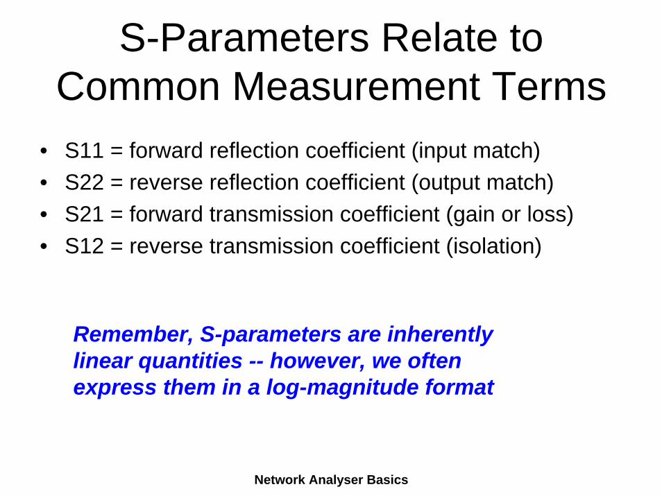
S-Parameters Relate to Common Measurement Terms
• S11 = forward reflection coefficient (input match)• S22 = reverse reflection coefficient (output match)• S21 = forward transmission coefficient (gain or loss)• S12 = reverse transmission coefficient (isolation)
Remember, S-parameters are inherentlylinear quantities -- however, we oftenexpress them in a log-magnitude format
Network Analyser Basics
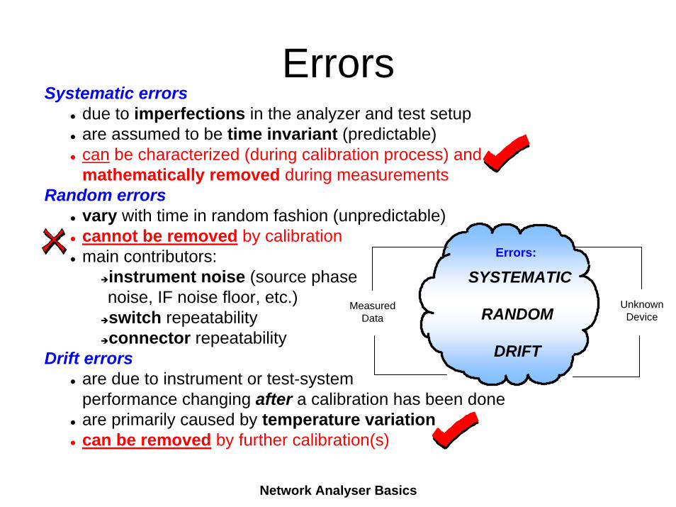
ErrorsSystematic errors
due to imperfections in the analyzer and test setupare assumed to be time invariant (predictable)can be characterized (during calibration process) andmathematically removed during measurements
Random errorsvary with time in random fashion (unpredictable)cannot be removed by calibrationmain contributors:
instrument noise (source phase noise, IF noise floor, etc.)switch repeatabilityconnector repeatability
Drift errorsare due to instrument or test-systemperformance changing after a calibration has been doneare primarily caused by temperature variationcan be removed by further calibration(s)
Unknown Device
Measured Data
SYSTEMATIC
RANDOM
DRIFT
Errors:
Network Analyser Basics
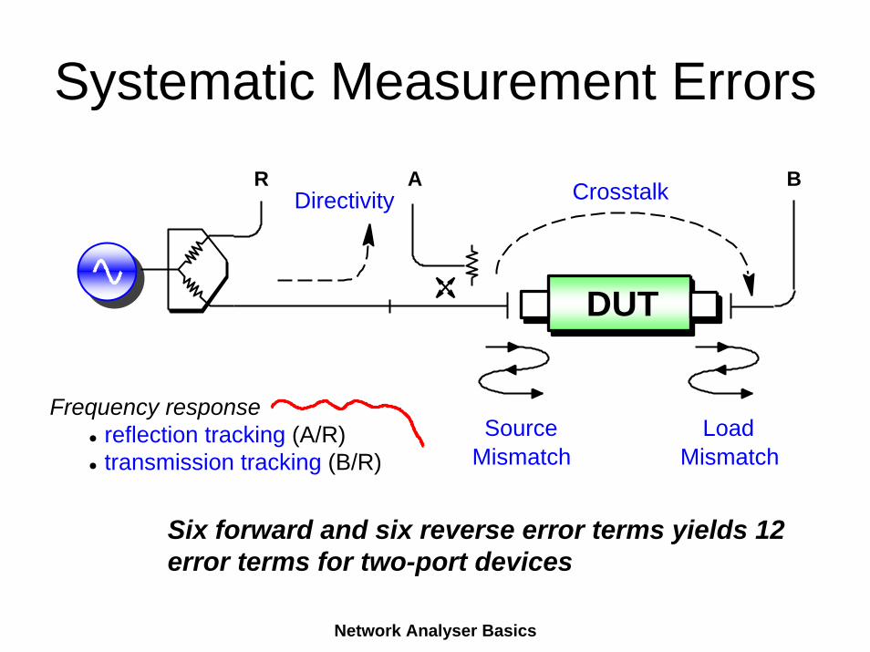
Systematic Measurement ErrorsA B
SourceMismatch
LoadMismatch
CrosstalkDirectivity
DUT
Frequency responsereflection tracking (A/R)transmission tracking (B/R)
R
Six forward and six reverse error terms yields 12 error terms for two-port devices
Network Analyser Basics
What is Calibration?
• Measure known device• Note measured value• Generate error table based on the
difference between known and measured values
• Subtract error from subsequent measurements
Network Analyser Basics
Standards Definitions
• Definitions are the parameters of an equivalent circuit network that represents the physical network– A standard may have a combination of a delay, a
loss, a capacitance, an inductance, a frequency range and a characteristic impedance
• Standards definitions must be known to the VNA– Enter manually – Load from disc
• A Cal Kit comes with the definitions of its standards.
Network Analyser Basics
Calibration Kits• Coaxial calibration kits come in type N, 7 mm, 3.5 mm,
2.92 mm, 2.4 mm, 1.0 mm and skripsie. (Bold available at E&E)
• Be sure not to exceed the frequency capability of the cables, adapters and calibration kit (remember session on connectors).
• There are waveguide calibration kits for every waveguide band. E&E has one for S-Band and one for X-Band.
• Remember that cal kits are expensive, and pieces of the cal kit should never be used as adapters or terminations.
• Always put the little plastic covers onto the cal kit pieces.
Network Analyser Basics
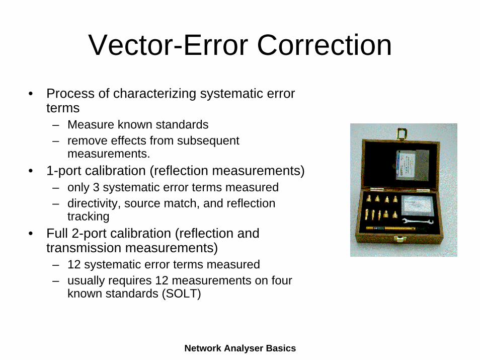
Vector-Error Correction• Process of characterizing systematic error
terms– Measure known standards– remove effects from subsequent
measurements.• 1-port calibration (reflection measurements)
– only 3 systematic error terms measured– directivity, source match, and reflection
tracking• Full 2-port calibration (reflection and
transmission measurements)– 12 systematic error terms measured– usually requires 12 measurements on four
known standards (SOLT)
Network Analyser Basics
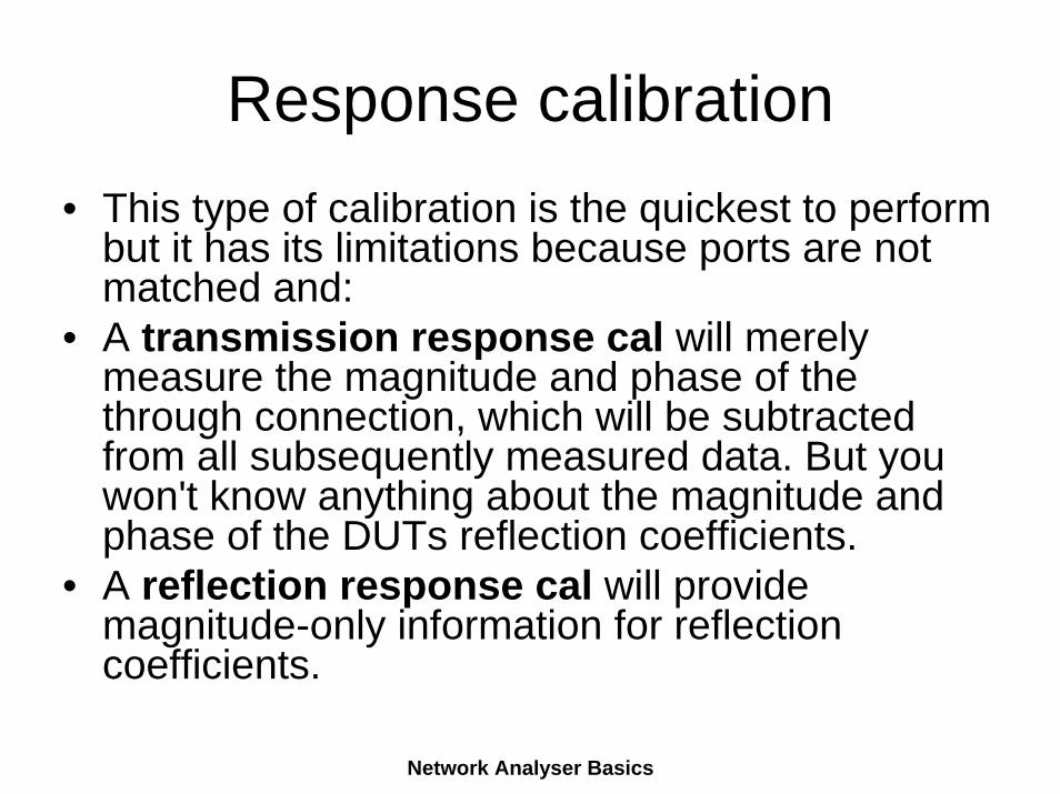
Response calibration• This type of calibration is the quickest to perform
but it has its limitations because ports are not matched and:
• A transmission response cal will merely measure the magnitude and phase of the through connection, which will be subtracted from all subsequently measured data. But you won't know anything about the magnitude and phase of the DUTs reflection coefficients.
• A reflection response cal will provide magnitude-only information for reflection coefficients.
Network Analyser Basics
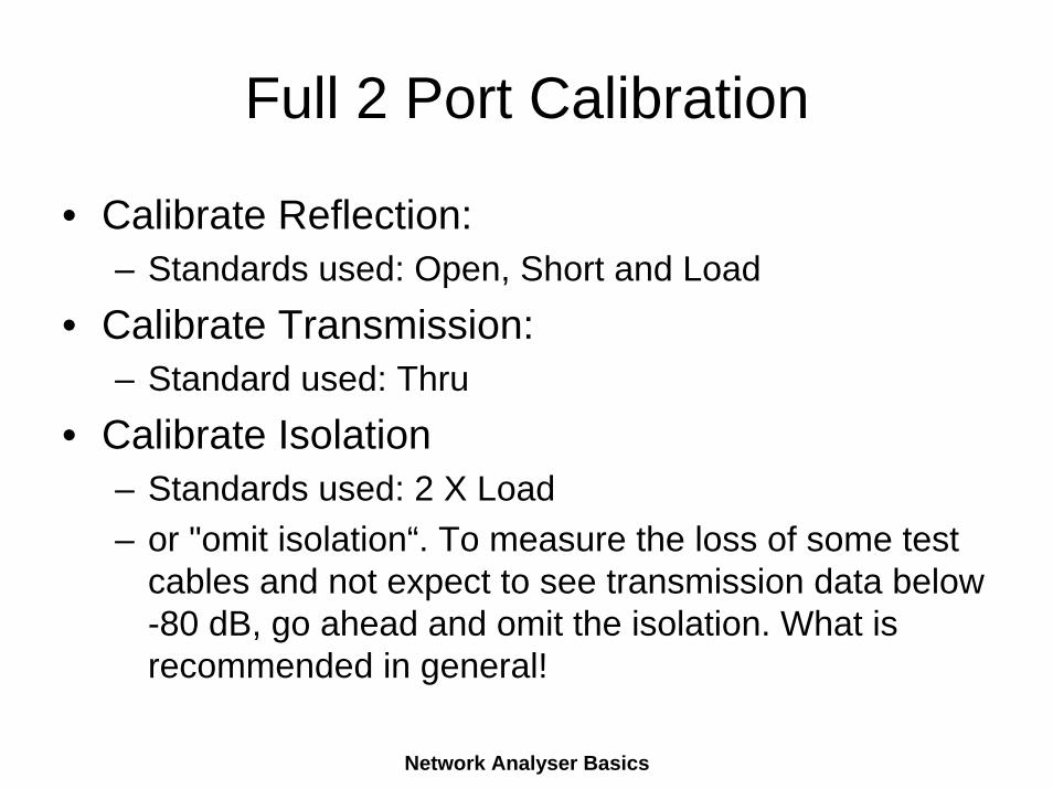
Full 2 Port Calibration
• Calibrate Reflection:– Standards used: Open, Short and Load
• Calibrate Transmission:– Standard used: Thru
• Calibrate Isolation– Standards used: 2 X Load– or "omit isolation“. To measure the loss of some test
cables and not expect to see transmission data below -80 dB, go ahead and omit the isolation. What is recommended in general!
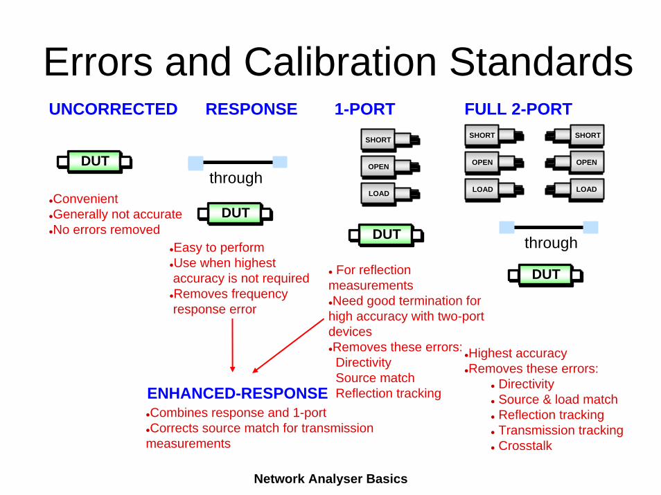
Highest accuracyRemoves these errors:
DirectivitySource & load matchReflection trackingTransmission trackingCrosstalk
UNCORRECTED RESPONSE 1-PORT FULL 2-PORT
ConvenientGenerally not accurateNo errors removed
Easy to performUse when highestaccuracy is not requiredRemoves frequencyresponse error
For reflection measurementsNeed good termination for
high accuracy with two-port devicesRemoves these errors:DirectivitySource matchReflection tracking
DUT
DUTDUT
DUT
OPEN
LOAD
OPEN
LOAD
OPEN
LOADthrough
through
ENHANCED-RESPONSECombines response and 1-portCorrects source match for transmission
measurements
SHORT SHORT SHORT
Errors and Calibration Standards
Network Analyser Basics
Network Analyser Basics
Verification - Validation
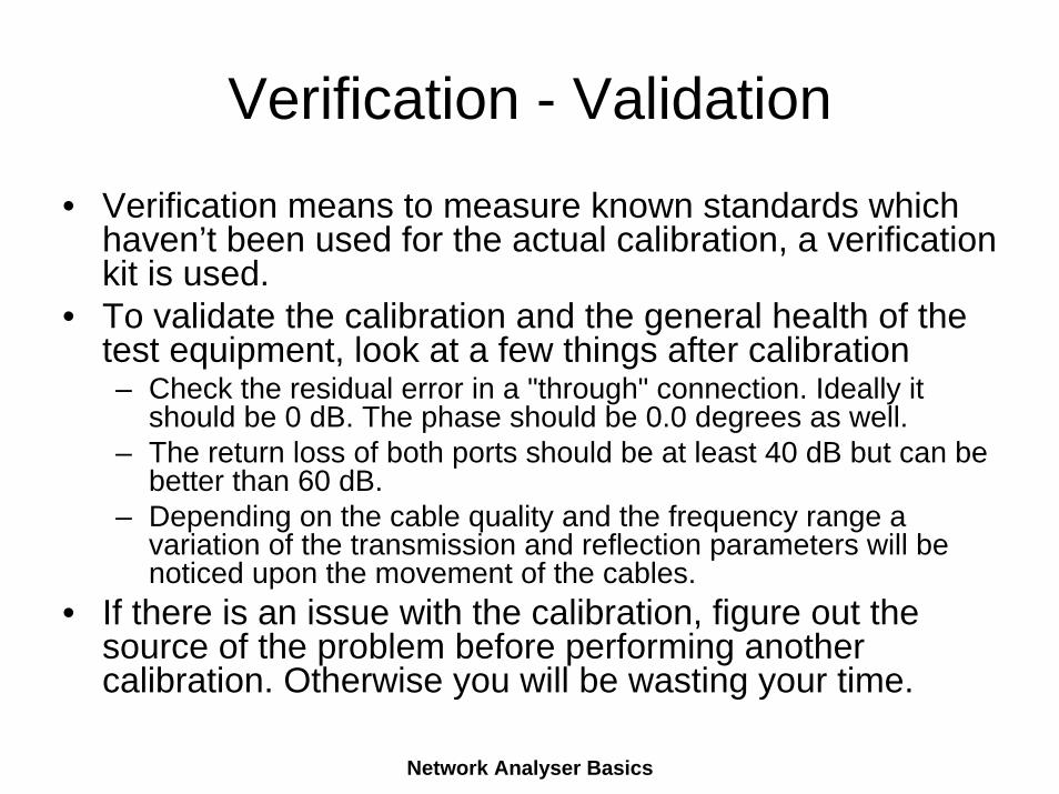
• Verification means to measure known standards which haven’t been used for the actual calibration, a verification kit is used.
• To validate the calibration and the general health of the test equipment, look at a few things after calibration– Check the residual error in a "through" connection. Ideally it
should be 0 dB. The phase should be 0.0 degrees as well.– The return loss of both ports should be at least 40 dB but can be
better than 60 dB.– Depending on the cable quality and the frequency range a
variation of the transmission and reflection parameters will be noticed upon the movement of the cables.
• If there is an issue with the calibration, figure out the source of the problem before performing another calibration. Otherwise you will be wasting your time.
Network Analyser Basics
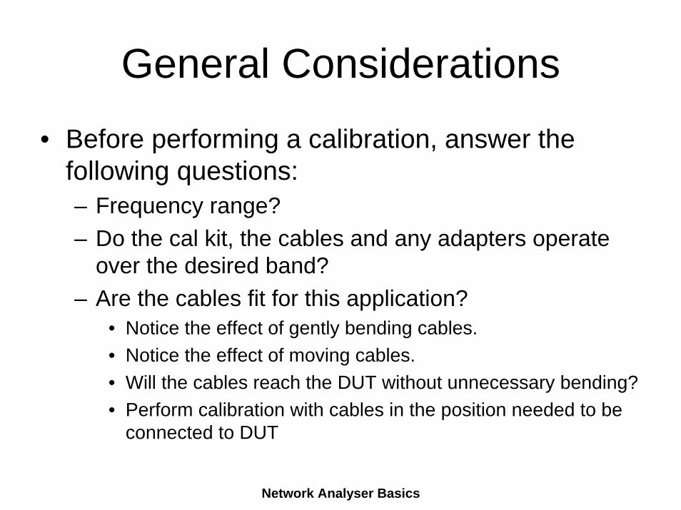
General Considerations
• Before performing a calibration, answer the following questions:– Frequency range? – Do the cal kit, the cables and any adapters operate
over the desired band? – Are the cables fit for this application?
• Notice the effect of gently bending cables.• Notice the effect of moving cables. • Will the cables reach the DUT without unnecessary bending?• Perform calibration with cables in the position needed to be
connected to DUT
Network Analyser Basics
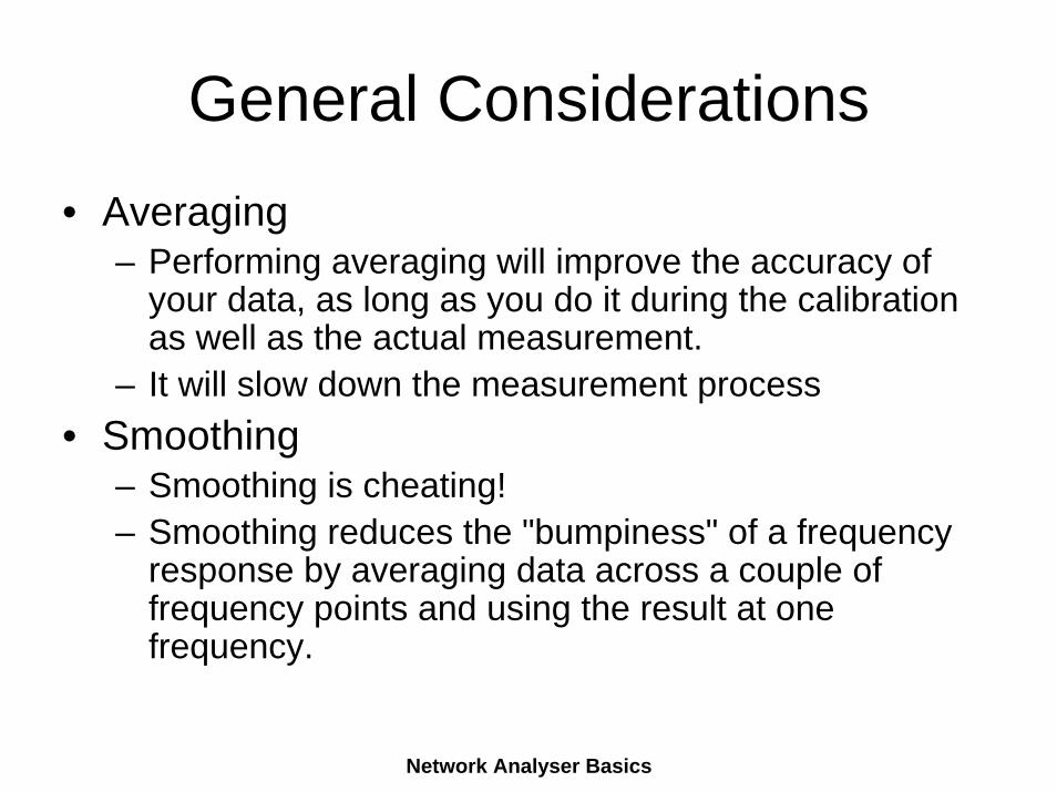
General Considerations• Averaging
– Performing averaging will improve the accuracy of your data, as long as you do it during the calibration as well as the actual measurement.
– It will slow down the measurement process• Smoothing
– Smoothing is cheating!– Smoothing reduces the "bumpiness" of a frequency
response by averaging data across a couple of frequency points and using the result at one frequency.
Network Analyser Basics
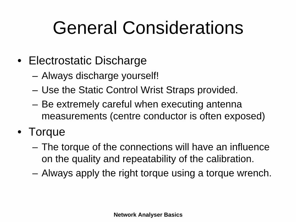
General Considerations
• Electrostatic Discharge– Always discharge yourself!– Use the Static Control Wrist Straps provided.– Be extremely careful when executing antenna
measurements (centre conductor is often exposed)• Torque
– The torque of the connections will have an influence on the quality and repeatability of the calibration.
– Always apply the right torque using a torque wrench.
Network Analyser Basics
Any Questions?
Thanks for your attention!See you upstairs R551 for the
VNA Demonstration!


![TLE ANALYSER · TLE ANALYSER User Manual v2.8 TLE analysis ... TLE ANALYSER Version 2.8 - 2013 TLE ANALYSER - User Manual [4] 2. TLE Analyser Setup and Options TLE Updater allow to](https://img.pdfslide.us/doc/110x75/5aa68a5c7f8b9a517d8ea13c/tle-analyser-analyser-user-manual-v28-tle-analysis-tle-analyser-version-28.jpg)