Embed Size (px)
Citation preview
Moving textures: Simulation of a ring sliding on a textured liner
Hugo M. Checo a,n, Roberto F. Ausas a, Mohammed Jai b, Jean-Paul Cadalen c,Franck Choukroun c, Gustavo C. Buscaglia a
a Inst. Ciências Matemáticas e de Computação, Univ. São Paulo, 13560-970 São Carlos, Brazilb ICJ, INSA de Lyon (Pôle de Mathématiques), 69621 Villeurbanne, Francec RENAULT, 67, Rue des Bons Raisins, 92508 Rueil Malmaison, France
a r t i c l e i n f o
Article history:Received 11 July 2013Received in revised form12 December 2013Accepted 18 December 2013Available online 25 December 2013
Keywords:Piston ringHydrodynamic lubricationMass-conservative modelPocketed surface
a b s t r a c t
Numerical simulations of the ring/liner contact in which the liner exhibits a periodic texture (pockets)are reported. The mass-conservative Elrod–Adams model is used to treat cavitation, and the dynamicsof the ring is considered with a linear mass that corresponds to actual engine compression rings.The results, computed at a Stribeck number of 10�3 and thus in the hydrodynamic lubrication regime,show that the ring profile determines whether pocketing is beneficial or not. For strongly non-conformalcontacts pocketing is detrimental, but for quasi-conformal contacts friction reductions of up to 73% arepredicted. The largest reduction in friction was obtained for textures consisting of close-packed arrays ofcircular pockets of diameter comparable to the size of the contact.
& 2013 Elsevier Ltd. All rights reserved.
1. Introduction
Texturing of contact surfaces to reduce friction and wear hasattracted much attention in the last years, especially since surfacemicroengineering techniques have become available. One importantapplication is the piston-ring/cylinder-liner contact in combustionengines, which accounts for about 5% of fuel consumption [1].
It is known that some texture is needed to avoid stictionbetween the ring pack and the liner, and honed liners have beenused for many decades for that purpose. Current investigations areaimed at determining the best texture in terms of friction andwear for each working condition.
Numerical and experimental studies on the ring/liner lubrica-tion problem with textured surfaces are recent and quite scarce.
The numerical studies have only considered the texture to beon the ring, and thus stationary with respect to the contact.Kligerman et al. [2] solved the problem for flat textured andpartially textured rings using the Reynolds equation and Reynoldsboundary condition, which is known not to conserve mass. Theyconcluded that surface texture reduces the friction between thesurfaces. On the other hand, Tomanik [3], with the same cavitationmodel, numerically compared barrel shaped rings (compression
rings), flat rings (oil control rings) and flat partially textured rings,also incorporating experimental data in the analysis. His results(both numerical and experimental) showed that the untexturedbarrel-shaped rings performed better than their flat, partiallytextured counterparts, both in hydrodynamic support and infriction coefficient. This finding coincides with recent numericalresults of Gadeschi et al. [4] assessing the effect of Laser SurfaceTexture (LST) pockets on barrel-shaped rings. These authorsadopted the Reynolds equation with Gümbel boundary conditions,which are non mass-conservative.
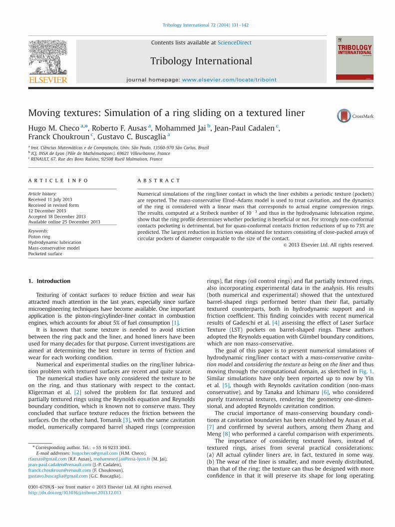
The goal of this paper is to present numerical simulations ofhydrodynamic ring/liner contact with a mass-conservative cavita-tion model and considering the texture as being on the liner and thusmoving through the computational domain, as sketched in Fig. 1.Similar simulations have only been reported up to now by Yinet al. [5], though with Reynolds cavitation condition (non-massconservative), and by Tanaka and Ichimaru [6], who consideredpurely transversal textures, rendering the geometry one-dimen-sional, and adopted Reynolds cavitation condition.
The crucial importance of mass-conserving boundary condi-tions at cavitation boundaries has been established by Ausas et al.[7] and confirmed by several authors, among them Zhang andMeng [8] who performed a careful comparison with experiments.
The importance of considering textured liners, instead oftextured rings, arises from several practical considerations:(a) All actual cylinder liners are, in fact, textured in some way.(b) The wear of the liner is smaller, and more evenly distributed,than that of the ring; the texture can thus be designed with moreconfidence in that it will preserve its shape for long operating
Contents lists available at ScienceDirect
journal homepage: www.elsevier.com/locate/triboint
Tribology International
0301-679X/$ - see front matter & 2013 Elsevier Ltd. All rights reserved.http://dx.doi.org/10.1016/j.triboint.2013.12.013
n Corresponding author. Tel.: þ55 16 9233 3043.E-mail addresses: [email protected] (H.M. Checo),
[email protected] (R.F. Ausas), [email protected] (M. Jai),[email protected] (J.-P. Cadalen),[email protected] (F. Choukroun),[email protected] (G.C. Buscaglia).
Tribology International 72 (2014) 131–142
times. (c) Since the rings contact the same axial position of theliner always at the same crank angle, texturing the liner allows oneto optimize the texture that contacts the ring independently foreach instant of the engine cycle.
The simulation of the ring/liner contact with texture on theliner also constitutes a scientific challenge from the numericalperspective. The dynamical behavior of the system is completelydifferent depending on whether the texture is on the ring or onthe liner. In the former case, the texture is stationary with respectto the contact, and thus the ring stabilizes at some position atwhich force equilibrium takes place. This position only changeswith the time scale of variations in the relative velocity or oil-feeding conditions. If the texture is on the liner, the texture cellsenter the contact from one side, move under the ring, and leavethe contact at the opposite side. In this case the ring exhibits asuperposed oscillatory motion with the time scale per/u, where peris the size of the texture cells and u the relative speed. Thecomplexity grows substantially, since the simulation must betransient and must incorporate the rigid-body dynamics of thering, which is subject to time-varying forces.
The simulations reported in this paper consider barrel-shapedrings in which the contact surface is cylindrical of radius R. Severalvalues of R are considered, ranging from 2 mm to nominallyconformal contact (R very large), so as to contribute to theinterpretation of experimental findings.
Experimental studies of textured surfaces have mainly focusedon conformal contacts (nominally flat pin or ring on nominallyplane disk) [8–13]. Experiments in non-conformal contact config-urations have yielded mixed results up to now. In a recent article,Kovalchenko et al. [14] found that dimpled disks accelerated thewear of the contacting ball and only as a result thereof somefriction reduction could be attained. Their explanation focused ona change of regime from boundary to mixed lubrication. Ali et al.[15] performed ball-on-disk experiments and found that dents didnot reduce friction in fully flooded conditions, whereas significantreduction was attained under severe starvation. Similar experi-ments by Li et al. [16] on PDMS disks lead them to conclude thattexturing only reduces friction at low sliding velocities, consistentwith a boundary or mixed lubrication regime. Other experimentalstudies of non-conformal contacts in the boundary lubricationregime have been reported by Kim et al. [17], Peterson andJacobson [18,19]
The hydrodynamic lubrication regime was studied by Costa andHutchins [20] by means of cylinder-on-plane experiments inwhich the texture was on the plane. For a cylinder diameter of16 mm they found that all textured surfaces performed worse thanthe untextured one. For a cylinder diameter of 200 mm, on the
other hand, they observed that the average film thickness, asmeasured by capacitance techniques, was improved by some non-zero textures. Unfortunately, they did not measure the minimumfilm thickness or the friction coefficient. Tomanik [21], on theother hand, used the compression ring of a heavy duty Dieselengine (RC50 mm) on several textured liners (pocketed andhoned liners) and obtained that the untextured liner presentedless friction than the textured ones. Some further information onthe effect of the liner0s striation patterns has been published byGrabon et al. [22] and by Yuan et al. [10], among others.
The plan of this paper is as follows: In Section 2 we describe themathematical model, which is essentially based on the Elrod–Adams model for lubrication and cavitation [23]. Though theElrod–Adams model has some deficiencies for this problem [24],there is no better general mass-conserving algorithm for cavitationproblems [25]. Section 3 contains the numerical results. Theycorrespond to fully flooded, hydrodynamic contact conditions atfixed relative velocity, and with atmospheric pressure (assumedequal to the cavitation pressure) on both sides of the ring. Thetexture is on the liner and its geometry corresponds to pocketsinspired in those produced by Laser Surface Texturing (LST) [26],with depth, diameter and area density in the range of thoserecommended in LST applications. The mass assigned to the ringis typical of compression rings of car engines. By exploringhundreds of cases, a picture of the effect of textures on ring/linerfriction emerges in which texturing is beneficial only for rings withsufficiently large R. This picture coincides with the one recentlyput forward by Gadeschi et al. [4] for non-moving textures(texture on the ring) on the basis of a non-mass-conservativemodel. Conclusions are drawn in Section 4.
2. Modeling
2.1. Geometrical model
We consider a configuration in which a single ring is in contactwith the liner. The surface of the liner is developed along the x1–x2plane, x1 being the axial direction (coincident with that of themotion) and x2 the circumferential one. The curvature along x2 isneglected.
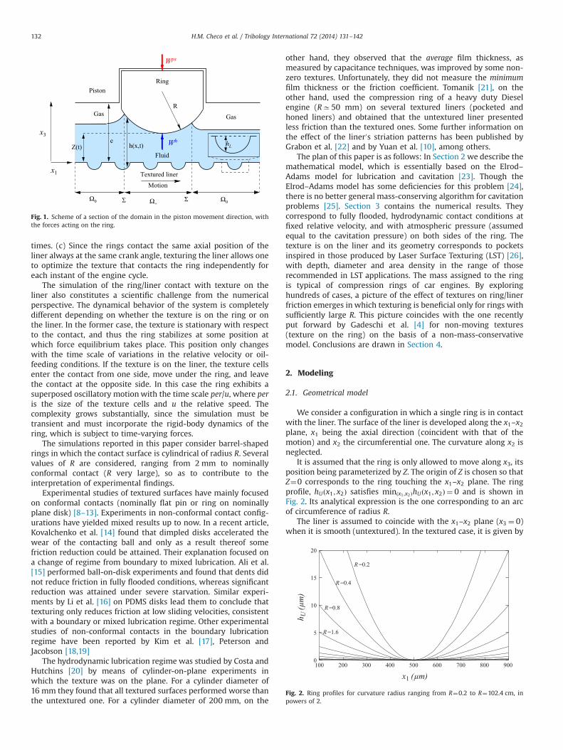
It is assumed that the ring is only allowed to move along x3, itsposition being parameterized by Z. The origin of Z is chosen so thatZ¼0 corresponds to the ring touching the x1–x2 plane. The ringprofile, hUðx1; x2Þ satisfies minðx1 ;x2ÞhUðx1; x2Þ ¼ 0 and is shown inFig. 2. Its analytical expression is the one corresponding to an arcof circumference of radius R.
The liner is assumed to coincide with the x1–x2 plane (x3 ¼ 0)when it is smooth (untextured). In the textured case, it is given by
Z(t)
GasGas
Piston
Fluidh(x,t)
e
Textured liner
Motion
Ring
x3
x1
Ω0 Σ Ω+Σ Ω0
Wps
hLWh
R
Fig. 1. Scheme of a section of the domain in the piston movement direction, withthe forces acting on the ring.
0
5
10
15
20
100 200 300 400 500 600 700 800 900
R =0.2
R =0.8
R =1.6
R =0.4
x1 (μm)
h U (μ
m)
Fig. 2. Ring profiles for curvature radius ranging from R¼0.2 to R¼102.4 cm, inpowers of 2.
H.M. Checo et al. / Tribology International 72 (2014) 131–142132
some function x3 ¼ �hLðx1; x2Þr0. We consider here texturepatterns inspired from LST surfaces (pocketed surfaces). Becauseof the arrangement of the pockets, the problem becomes periodicin x2, so that in the simulation only one period is considered,0ox2oB, with suitable boundary conditions at x2 ¼ 0 and x2 ¼ B.
The ring follows a uniform motion along x1 with velocity �u.We adopt a frame of reference that moves with the ring, so thatthe velocity of the lower surface (liner) becomes u and the x1-location of the ring is fixed between x1 ¼ a and x1 ¼ b. Outside ofthe ring0s position the gap between the surfaces is assumed to beuniform of thickness e (notice that this implies, in particular, thatthe ring axis is centered and aligned with the cylinder, whichconstitutes of course an idealization).
Under the assumptions above, the gap between the ring andthe liner is given by
hðx1; x2; tÞ ¼hLðx1�u t; x2ÞþhUðx1; x2ÞþZðtÞ if aox1ob
hLðx1�u t; x2Þþe otherwise
(ð1Þ
2.2. Forces on the ring
The dynamics of the ring is governed by the forces acting on italong the x3-direction. These forces are described below.
The pre-stress force comes from the elastic response of the ringto the deformation needed to make it fit into its placement.It points outwards (i.e., along �x3) and can be assumed constant.We denote by Wps its value per unit length along x2.
The hydrodynamic force originates from the pressure pðx1; x2; tÞthat develops in the oil film between the ring and the liner. Itsvalue per unit length along x2 is given by
WhðtÞ ¼ 1B
Z b
a
Z B
0pðx1; x2; tÞ dx1 dx2 ð2Þ
The pressure field p comes out from the hydrodynamic model thatis described in the next subsection.
From the above considerations, if m is the mass of the ring perunit length, then the dynamical equation for the ring0s displace-ment reads as
md2Z
dt2¼WpsðtÞþWhðtÞ ð3Þ
This is supplemented with initial conditions for Z and Z0 at t¼0.For the model to be in closed form it only remains to explain thecalculation of the hydrodynamic pressure p.
2.3. Hydrodynamics and cavitation modeling
We adopt here the well-known Elrod–Adams model [23],which incorporates into a single formulation Reynolds equationfor the pressurized region and Jacobsson–Floberg–Olsson bound-ary conditions. This model is mass conserving, which as shown by[7] is essential for obtaining physically meaningful results inlubrication problems involving textured surfaces.
The model postulates the computation of two fields, p and θ,which correspond to the hydrodynamic pressure and to anauxiliary saturation-like variable, respectively, which (weakly)satisfy the equation
∇ � h3
12μ∇p
!¼ uðtÞ
2∂ hθ∂x1
þ∂ hθ∂t
ð4Þ
under the complementarity conditions:
p40 ) θ¼ 1θo1 ) p¼ 00rθr1
8><>: ð5Þ
where μ is the viscosity of oil.This model has been analyzed to a great extent by [27,28], and
it has been shown to lead to well-posed problems in severalphysically meaningful situations. For the piston ring/liner contactwe assume that the oil-film thickness is known (and constant,equal to doil) far away from the ring assembly. This amounts toimposing that θ¼ doil=h at the boundary of the computationaldomain. More precisely, if the computational domain correspondsto x1ℓox1ox1r , then assuming u40 we impose θðx1ℓ; x2; tÞ ¼doil=hðx1ℓ; x2; tÞ. As already said, the boundary conditions alongx2 ¼ 0 and x2 ¼ B are defined so as to enforce the proper periodi-city in that direction. An initial condition for θ is also provided.
As a consequence of the previous model, at each instant thedomain spontaneously divides into a pressurized region, Ωþ ,where p40, and a cavitated region, Ω0, where the film is not full(θo1, see Fig. 1). At the boundary between Ωþ and Ω0, the so-called cavitation boundary Σ, the Elrod–Adams model automati-cally enforces the mass-conservation condition:
h3
12μ∇p � n ¼ u
2ð1�θÞhn � ı ð6Þ
where n is the normal to Σ (oriented outwards from Ω0) and ı isthe unit vector along x1. In particular, the saturation field θ turnsout to be discontinuous at those parts of Σ where u n � i is positive(reformation boundary).
If the gap thickness h is discontinuous at the cavitationboundary, which is often the case in the textured case, Eq. (6)does not hold. However, the Elrod–Adams model considered as aconservation law ∂tφþ∇ � J ¼ 0, with φ¼ hθ, remains in generalwell-posed and provides a physically meaningful solution (thetheory is somewhat fragmented and does not cover all possibleconditions, but sufficient evidence exists to safely assume well-posedness under initial and boundary conditions that makephysical sense).
2.4. Friction losses
The friction force per unit width is given by
F ¼ �1B
Z b
a
Z B
0
μu gðθÞh
þ12h∂p∂x1
þp∂hL∂x1
� �dx1 dx2 ð7Þ
where the function gðθÞ is taken as
gðθÞ ¼ θ sðθÞ ð8Þwith sðθÞ is the switch function:
sðθÞ ¼ 1 if θ4θs
0 otherwise
(ð9Þ
In this friction model θs is a threshold for the onset of friction,interpreted as the minimum oil fraction for shear forces to betransmitted from one surface to the other. In most of the calcula-tions the value θs ¼ 0:95 has been adopted. Notice that hL corre-sponds to the texture depth at each location, which changes withtime as the texture moves below the ring. All oil films obtained inthe simulations are thick enough to exclude the possibility ofcontact between the lubricated surfaces, so that solid–solid fric-tion is not considered.
The friction coefficient then results from
f ¼ �FWps ð10Þ
H.M. Checo et al. / Tribology International 72 (2014) 131–142 133
Remark: The term p∂hL=∂x1 is not a shear force. Instead, itcorresponds to the projection of the pressure force along x1 whenthe normal to the liner is not along x3. Since the liner is moving tothe right, ∂hL=∂x140 corresponds to a converging wedge whichwill produce a pressure force with a negative x1 component, thusopposing the motion. Similarly, ∂hL=∂x1o0 corresponds to adiverging wedge which will produce a pressure force with apositive x1 component, thus assisting the motion. Since in generalthe pressure in converging wedges is higher than in divergingones, this term is always negative and thus always contributespositively to the friction. Notice that this term is omitted in theliterature, which mostly considers textures on the stationarysurface.
2.5. Adimensionalization and final equations
We consider an adimensionalization of the equations based onthe following fundamental scales:
Quantity Scale Scale value adopted
Velocity U 10 m/sLength L 1 cmGap thickness H 1 μm
These scales, together with the viscosity of the oil, assumed tobe μ¼ 0:004 Pa s lead to the following derived scales for thedifferent quantities:
Quantity Scale Scale value Name
x1; x2 L 10�2 mR L 10�2 m Ring profile curvature radiust L
U10�3 s Time
h H 10�6 m Gap thicknessZ H 10�6 m Ring0s radial positionp 6μUL
H22:4� 109 Pa Pressure
Wps;Wh 6μUL2
H2
2:4� 107 N=m Radial forces per unit width
F μULH
4� 102 N=m Friction force per unit width
m 6L4μH3U
2:4� 107 kg=m Mass per unit width
Notice that, since the scales for radial and friction forces aredifferent, the friction coefficient is given by
f ¼ H6L
F
Wps ð11Þ
where the carets (hats) denote the corresponding non-dimensional quantity.
Upon adimensionalization of all variables, and omitting allcarets for simplicity, let us collect the complete mathematicalproblem to be solved:
Find trajectory Z(t), and fields p(t), θðtÞ, defined onΩ¼ ðx1ℓ; x1rÞ � ð0;BÞ and periodic in x2, satisfying
Zð0Þ ¼ Z0; Z0ð0Þ ¼ V0;
θðx1ℓ; x2; tÞ ¼ doil=hðx1ℓ; x2; tÞ 8x2 Að0;BÞp40 ) θ¼ 1θo1 ) p¼ 00rθr1
8>>>>>><>>>>>>:
ð12Þ
and
md2Z
dt2¼WpsðtÞþWhðtÞ ð13Þ
∇ � ðh3∇pÞ ¼ u2∂ hθ∂x1
þ∂ hθ∂t
ð14Þ
where
hðx1; x2; tÞ ¼hLðx1�u t; x2ÞþhU ðx1; x2ÞþZðtÞ if aox1ob
hLðx1�u t; x2Þþe otherwise;
(ð15Þ
WhðtÞ ¼ 1B
Z b
a
Z B
0pðx1; x2; tÞ dx1 dx2; ð16Þ
and the functions WpsðtÞ, hLðx1; x2Þ, hU ðx1; x2Þ are known explicitly.The formula for the adimensional friction force per unit width
is
F ¼ 1B
Z b
a
Z B
0
μu gðθÞh
þ3h∂p∂x1
þ6p∂hL∂x1
� �dx1 dx2 ð17Þ
It is thus composed of three terms, which are usually called(in order) Couette term, Poiseuille term and Pressure term.
2.6. Numerics
The numerical treatment is exactly as described in [29]. Itconsists of a finite volume, conservative method with upwindingdiscretization of the Couette flux and centered discretization of thePoiseuille flux and an iterative imposition of the cavitation condi-tions by means of a Gauss–Seidel-type algorithm. The dynamicalequation for Z(t) is discretized by a Newmark scheme, which isbuilt into the overall iterative process. The simulations would nothave been possible without significant acceleration obtained frommultigrid techniques [30].
3. Numerical simulations
3.1. Preliminaries and definitions
The performance of the different contacts under study isassessed at conditions of low applied load, corresponding to aStribeck parameter of 10�3. The Stribeck parameter S is defined by
S¼ μ uWps ð18Þ
where μ, u and Wps are dimensional. In terms of the non-dimensional variables used in the code, the expression is (herewe temporarily put carets on non-dimensional variables to avoidconfusion, but they are dropped hereafter)
S¼ H2
6L2u
Wps ð19Þ
For any value of S, the friction factor f is a function of time, since itchanges as the textures change position under the ring. However,since the studied textures are periodic, f reaches a periodic regimeafter a few passages of individual textures (see Fig. 5 for a concreteexample). So does the ring position Z and, as a consequence, theminimum clearance C between the surfaces.
In our assessment, the average friction coefficient f is used toquantify friction, where the average is performed over one periodof the motion once the ring has attained the periodic regime. Toquantify wear, on the other hand, we report the minimumclearance Cmin, defined as the minimal separation between thesurfaces over the period.
H.M. Checo et al. / Tribology International 72 (2014) 131–142134
3.2. Pocketed surfaces
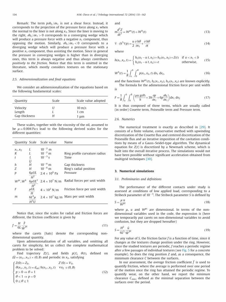
We consider surfaces exhibiting dimples with the contour of anellipse (see Fig. 3), with the ellipse semiaxis l1 oriented along thepiston movement direction and l2 orthogonal to it. The dimples0cen-ters are separated by distances per and width along these directions.In the cases under study the dimples are arranged in a square motif(per¼width). We consider dimples that have the shape of half anellipsoid of semiaxis prof orthogonal to the liner surface.
3.3. Mesh convergence
Amesh convergence study is needed to prove the soundness of thenumerical method under moving-texture conditions. Consider thecase of a pocketed liner with parameters per¼0.06, l1¼0.01, l2¼0.01,prof¼5.0, u¼1.0 and Wps ¼ 1:66� 10�6, corresponding to S¼ 10�3,with a linear ring mass of 2:0� 10�9 (which is a realistic value). Thesimulation starts with the ring separated 2.5 μm from the liner0splateau (Zð0Þ ¼ 2:5), with zero velocity (Z0ð0Þ ¼ 0). The domain is0.2 cm in the axial direction (x1) and 300 μm along x2 (just half thedomain is simulated, with reflection boundary conditions).
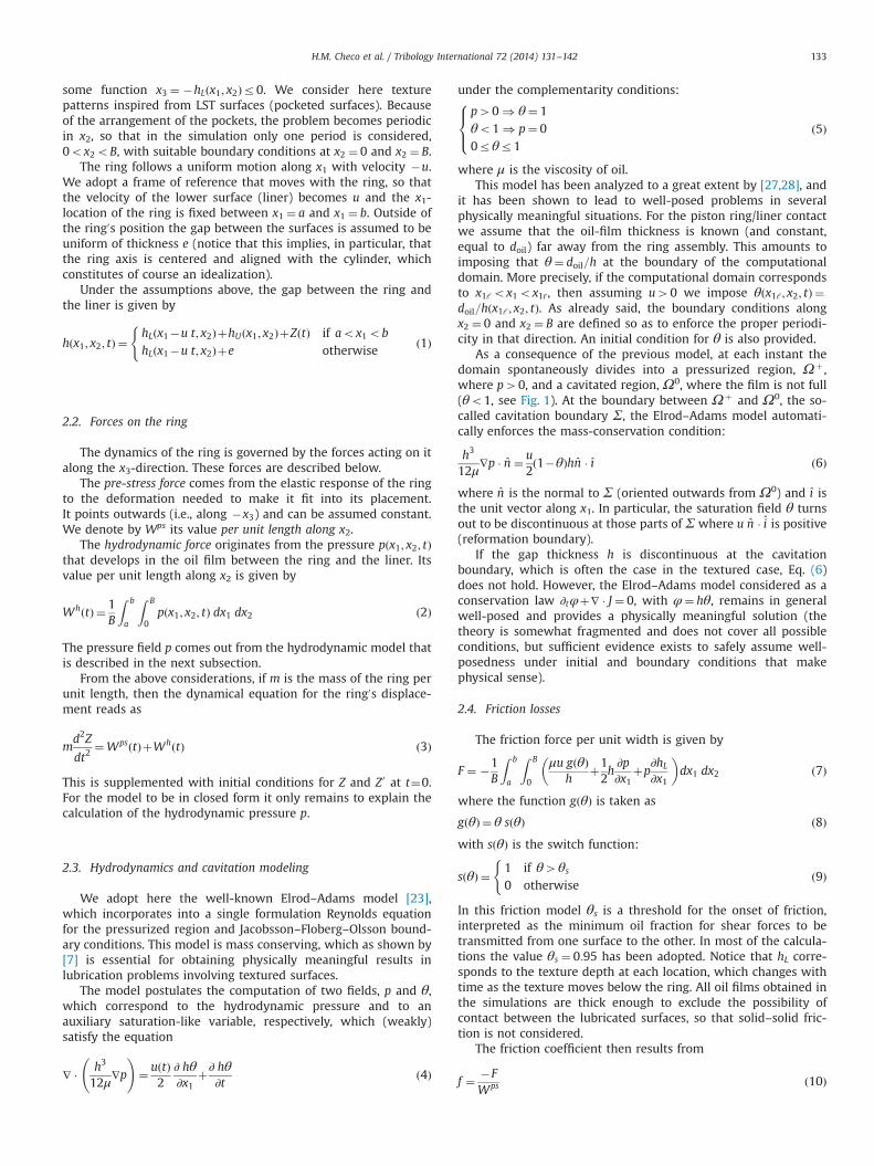
A 512�32 spatial mesh is considered as a starting point for therefinement, with time step δt ¼ 4� 10�4, for 1.6 s of simulation.The refined meshes have 1024�64 cells (run with δt ¼ 2� 10�4)and 2048�128 cells (run with δt ¼ 10�4). Fully flooded condi-tions are taken (fluid film of 20 μm imposed at the left boundary).
Fig. 4 shows the position x1 of the cavitation boundary alongthe line x2 ¼ per=2 (corresponding to the longitudinal line passingthrough the dimples0 centers) as a function of time. Though thecavitation boundary is a very sensitive variable, it can be seen thatits position for each time converges steadily (with roughly firstorder in the mesh size).
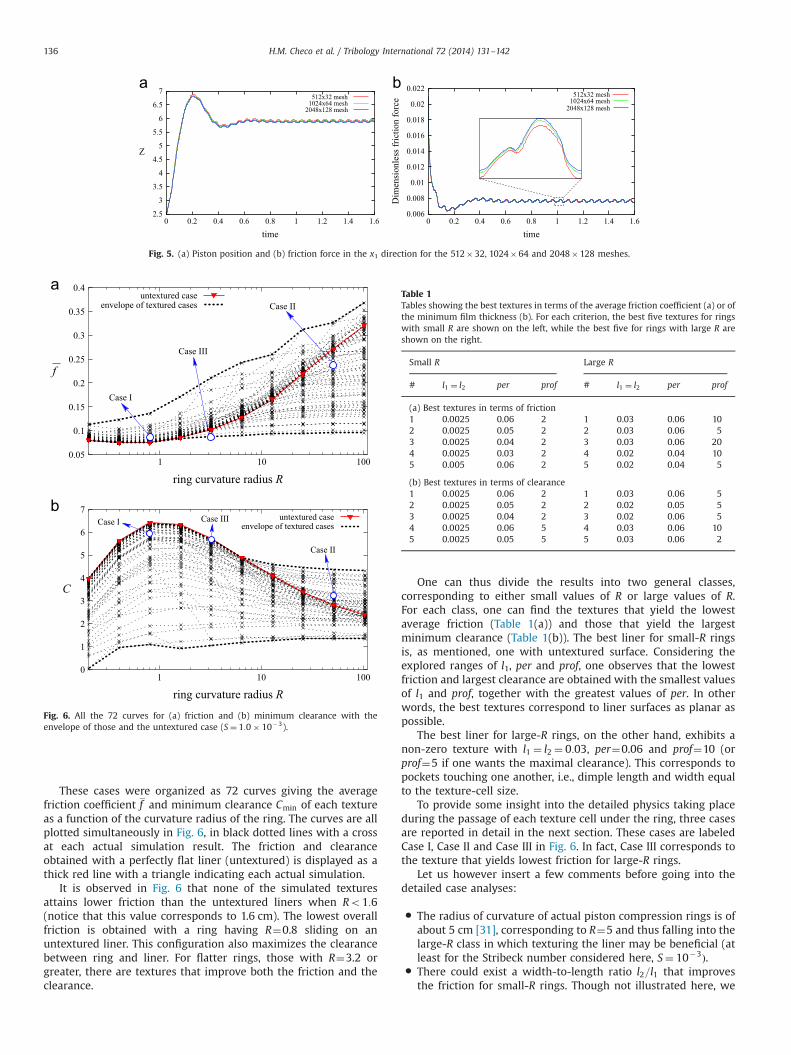
Let us now turn to the convergence of the friction force, since itwill be the focus of the results in the next sections. In Fig. 5(b) thetotal friction force versus time, and a detail thereof, is shown. Asmentioned, there is an adjustment period of about 1 time unituntil the ring reaches its stable motion, which is periodic in timewith period per=u. Convergence of the friction force is observed inthe figure, both in the initial transient and in the periodic regime.The relative errors in the average friction force in the periodicregime on the meshes with 512�32 and 1024�64 cells, ascompared to those computed on the 2048�128 mesh, are of0.72% and 0.27%, respectively. The numerical errors for thecomputations made on the 512�32 mesh, therefore, can beestimated at 1%. It is this mesh that is employed in all thecomputations presented heretoforth, though some of them havebeen computed in all three meshes to check that the claimedconclusions are not consequences of numerical artifacts.
3.4. Effect of surface texturing on friction for different ring profiles
This study considers the cylindrical ring profiles shown inFig. 2. The Stribeck number is fixed at S¼ 10�3 (hydrodynamicregime) and the inlet oil thickness chosen so as to yield fullyflooded conditions (doil ¼ 20). The other parameters are u¼1,Wps ¼ 1:66� 10�6, and a linear ring mass of 2:0� 10�9, as before.A range of the parameters that define the texture shape wasexplored, simulating for each texture shape the transient lubrica-tion problem for 10 different ring shapes (non-dimensionalcurvature radii from R¼0.2 to R¼102.4). Specifically, all combina-tions of the values of the three parameters l1 (pocket length, takenequal to its width l2), per (texture-cell length, taken equal to itswidth) and prof (pocket depth) were computed for ten differentvalues of R. This yields a total of 8� 6� 5� 10¼ 2400 cases.Excluding those combinations which are geometrically incompa-tible (because 2l14per) and those which do not satisfy the thinfilm hypothesis (because l1o5 prof ), there remain 720 cases:
l1 ¼ l2 Period Depth
0.001 0.005 20.0025 0.005 50.005 0.01 100.01 0.02 200.02 0.03 300.03 0.04
0.050.06
Movement direction
l1
l2
x2
x1
per
width
Fig. 3. (a) Pocketed texture and (b) Ellipsoidal-bottomed dimple.
time
0.8
0.9
1.1
1.2
1.3
1.4
1.5
1.6
1
1.28 1.3 1.32 1.34 1.36
1024x64 mesh512x32 mesh2048x128 mesh
x1
Fig. 4. Position x1 of the cavitation boundaries on the line x2 ¼ per=2, which passesthrough the dimples0 centers. Shown are the results for the 512�32, 1024�64 and2048�128 meshes, exhibiting convergent behavior of first order.
H.M. Checo et al. / Tribology International 72 (2014) 131–142 135
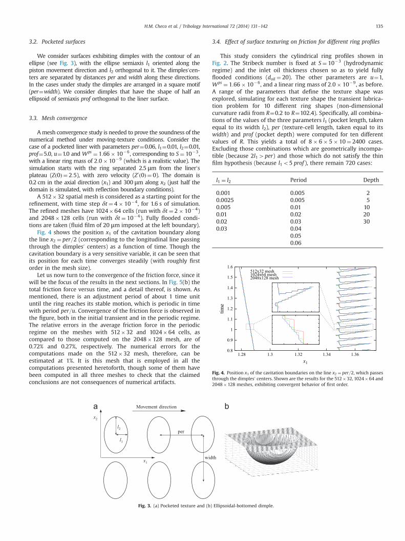
These cases were organized as 72 curves giving the averagefriction coefficient f and minimum clearance Cmin of each textureas a function of the curvature radius of the ring. The curves are allplotted simultaneously in Fig. 6, in black dotted lines with a crossat each actual simulation result. The friction and clearanceobtained with a perfectly flat liner (untextured) is displayed as athick red line with a triangle indicating each actual simulation.
It is observed in Fig. 6 that none of the simulated texturesattains lower friction than the untextured liners when Ro1:6(notice that this value corresponds to 1.6 cm). The lowest overallfriction is obtained with a ring having R¼0.8 sliding on anuntextured liner. This configuration also maximizes the clearancebetween ring and liner. For flatter rings, those with R¼3.2 orgreater, there are textures that improve both the friction and theclearance.
One can thus divide the results into two general classes,corresponding to either small values of R or large values of R.For each class, one can find the textures that yield the lowestaverage friction (Table 1(a)) and those that yield the largestminimum clearance (Table 1(b)). The best liner for small-R ringsis, as mentioned, one with untextured surface. Considering theexplored ranges of l1, per and prof, one observes that the lowestfriction and largest clearance are obtained with the smallest valuesof l1 and prof, together with the greatest values of per. In otherwords, the best textures correspond to liner surfaces as planar aspossible.
The best liner for large-R rings, on the other hand, exhibits anon-zero texture with l1 ¼ l2 ¼ 0:03, per¼0.06 and prof¼10 (orprof¼5 if one wants the maximal clearance). This corresponds topockets touching one another, i.e., dimple length and width equalto the texture-cell size.
To provide some insight into the detailed physics taking placeduring the passage of each texture cell under the ring, three casesare reported in detail in the next section. These cases are labeledCase I, Case II and Case III in Fig. 6. In fact, Case III corresponds tothe texture that yields lowest friction for large-R rings.
Let us however insert a few comments before going into thedetailed case analyses:
� The radius of curvature of actual piston compression rings is ofabout 5 cm [31], corresponding to R¼5 and thus falling into thelarge-R class in which texturing the liner may be beneficial (atleast for the Stribeck number considered here, S¼ 10�3Þ.
� There could exist a width-to-length ratio l2=l1 that improvesthe friction for small-R rings. Though not illustrated here, we
512x32 mesh1024x64 mesh
2048x128 mesh
2.5
3
3.5
4
4.5
5
5.5
6
6.5
7
time
Z
512x32 mesh1024x64 mesh
2048x128 mesh
0.006
0.008
0.01
0.012
0.014
0.016
0.018
0.02
0.022
0 0.2 0.4 0.6 0.8 1 1.2 1.4 1.6 0 0.2 0.4 0.6 0.8 1 1.2 1.4 1.6
time
Dim
ensi
onle
ss fr
ictio
n fo
rce
Fig. 5. (a) Piston position and (b) friction force in the x1 direction for the 512�32, 1024�64 and 2048�128 meshes.
Case II
Case III
Case I
untextured caseenvelope of textured cases
0.05
0.1
0.15
0.2
0.25
0.3
0.35
0.4
100101
ring curvature radius R
ring curvature radius R
f
Case I Case III
Case II
untextured caseenvelope of textured cases
0
1
2
3
4
5
6
7
100101
C
Fig. 6. All the 72 curves for (a) friction and (b) minimum clearance with theenvelope of those and the untextured case (S¼ 1:0� 10�3).
Table 1Tables showing the best textures in terms of the average friction coefficient (a) or ofthe minimum film thickness (b). For each criterion, the best five textures for ringswith small R are shown on the left, while the best five for rings with large R areshown on the right.
Small R Large R
# l1 ¼ l2 per prof # l1 ¼ l2 per prof
(a) Best textures in terms of friction1 0.0025 0.06 2 1 0.03 0.06 102 0.0025 0.05 2 2 0.03 0.06 53 0.0025 0.04 2 3 0.03 0.06 204 0.0025 0.03 2 4 0.02 0.04 105 0.005 0.06 2 5 0.02 0.04 5
(b) Best textures in terms of clearance1 0.0025 0.06 2 1 0.03 0.06 52 0.0025 0.05 2 2 0.02 0.05 53 0.0025 0.04 2 3 0.02 0.06 54 0.0025 0.06 5 4 0.03 0.06 105 0.0025 0.05 5 5 0.03 0.06 2
H.M. Checo et al. / Tribology International 72 (2014) 131–142136
explored other pocket shapes, with l2=l1 ¼ 0:25, 0.5, 2 and 4,and none of them yielded better performances than circularpockets.
3.5. Analysis of three cases
Here we analyze and compare the following three cases:
� Case I: A textured liner with l1 ¼ l2 ¼ 0:01, per¼0.06 and prof¼5.0,combined with a ring having R¼0.8. In this configuration, thetextured liner yields higher friction and lower clearance than theuntextured one. The textured area fraction is 8.7%.
� Case II: The same textured liner (l1 ¼ l2 ¼ 0:01, per¼0.06 andprof¼5.0) now combined with a large-R ring (R¼51.2). In thisconfiguration the texture is beneficial both in friction and inclearance. The textured area fraction is 8.7%.
� Case III: A textured liner with l1 ¼ l2 ¼ 0:03, per¼0.06 andprof¼10.0, combined with a ring having R¼3.2. This corre-sponds to the texture yielding the lowest friction for the givenvalue of R. The textured area fraction is 78.5%.
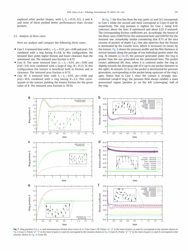
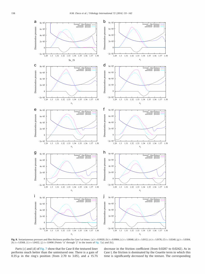
In Fig. 7, the first line from the top (parts (a) and (b)) correspondsto Case I, while the second and third correspond to Cases II and III,respectively. The ring position is highest for Case I, being 6.41(microns) above the liner if untextured and about 6.25 if textured.The corresponding friction coefficients are, accordingly, the lowest ofthe three cases (0.00754 for the untextured liner and 0.00763 for thetextured one, remarkably similar considering that 8.7% of the areaconsists of pockets of depth 5 μ). One also observes that the frictionis dominated by the Couette term, which is increased (in mean) bythe texture. Fig. 8 shows the pressure profile and the film thickness atseveral instants along the passage of one individual pocket under thering. At instants (c) to (f), the pressure generated under the ring isgreater than the one generated on the untextured liner. The pocketcreates additional lift, thus, when it is centered under the ring orslightly towards the diverging side of it (up to one pocket diameter tothe right). At instants (h) to (a) the pocket is detrimental for pressuregeneration, corresponding to the pocket being upstream of the ring0sapex. Notice that in Case I, since the contact is strongly non-conformal (small-R ring), the pressure field always exhibits a mainpressurized region (positive p) on the left (converging) half ofthe ring.
a
b
c
d e
f
g
hi
j
untextured runnertextured runner
2.5
3
3.5
4
4.5
5
5.5
6
6.5
7
7.5
time
Rin
g po
sitio
n Z a
bc d
fe gh
ij
Couette − untexturedPoiseuille − untextured
Total − untexturedCouette − textured
Poiseuille − texturedPressure − textured
Total − textured
0
time
fric
tion
coef
ficie
nt0.25
0.15
0.10
0.20
0.05
−0.05
a bc
de f
g
i jh
2.5
2.6
2.7
2.8
2.9
3
3.1
3.2untextured case
textured case
time
Rin
g po
sitio
n Z
a e
g
b
cd f
h
i
j
0
time
Total − texturedPressure − textured
Poiseuille − textured
Total − untexturedCouette − textured
Poiseuille − untexturedCouette − untextured
fric
tion
coef
ficie
nt
0.35
0.30
0.25
0.20
0.15
0.10
0.05
−0.05
ac
de
g
jihb
f
untextured casetextured case
2.5
3
3.5
4
4.5
5
5.5
6
time
Rin
g po
sitio
n Z
ab
c
de
f g h i j
Poiseuille − untexturedTotal − untexturedCouette − textured
Poiseuille − texturedPressure − textured
Total − textured
0
0 0.2 0.4 0.6 0.8 1 1.2 1.4 1.6 0 0.2 0.4 0.6 0.8 1 1.2 1.4 1.6
0 1 2 3 4 5 6 7 0 1 2 3 4 5 6 7
0 0.2 0.4 0.6 0.8 1 1. 2 1.4 1.6 0 0.2 0.4 0.6 0.8 1 1.2 1.4 1.6
time
Couette − untextured
fric
tion
coef
ficie
nt
0.30
0.25
0.20
0.15
0.10
0.05
−0.05
Fig. 7. Ring position Z (a, c, e) and instantaneous friction force terms (b, d, f) for Cases I–III. Points “a”–“j” in the inset of parts (a) and (b) correspond to the instants shown inFig. 8 (Case I). Points “a”–“j” in the inset of parts (c) and (d) correspond to the instants shown in Fig. 9 (Case II). Points “a”–“j” in the inset of parts (e) and (f) correspond to theinstants shown in Fig. 10 (Case III).
H.M. Checo et al. / Tribology International 72 (2014) 131–142 137
Parts (c) and (d) of Fig. 7 show that for Case II the textured linerperforms much better than the untextured one. There is a gain of0.35 μ in the ring0s position (from 2.70 to 3.05), and a 15.7%
decrease in the friction coefficient (from 0.0287 to 0.0242). As inCase I, the friction is dominated by the Couette term in which thistime is significantly decreased by the texture. The corresponding
−2e−05
0
2e−05
4e−05
6e−05
8e−05
Dim
ensi
onle
ss p
ress
ure
$x_1$
textured − film thicknesstextured − pressure
untextured − pressure
Dim
ensi
onle
ss p
ress
ure
textured − film thicknesstextured − pressure
untextured − pressure
−2e−05
0
2e−05
4e−05
6e−05
8e−05
Dim
ensi
onle
ss p
ress
ure
textured − film thicknesstextured − pressure
untextured − pressure
Dim
ensi
onle
ss p
ress
ure
textured − film thicknesstextured − pressure
untextured − pressure
−2e−05
0
2e−05
4e−05
6e−05
8e−05
Dim
ensi
onle
ss p
ress
ure
textured − film thicknesstextured − pressure
untextured − pressure
Dim
ensi
onle
ss p
ress
ure
textured − film thicknesstextured − pressure
untextured − pressure
x1x1
x1
x1
x1
x1x1
x1x1
−2e−05
0
2e−05
4e−05
6e−05
8e−05
Dim
ensi
onle
ss p
ress
ure
textured − film thicknesstextured − pressure
untextured − pressure
Dim
ensi
onle
ss p
ress
ure
textured − film thicknesstextured − pressure
untextured − pressure
−2e−05
0
2e−05
4e−05
6e−05
8e−05
−2e−05
0
2e−05
4e−05
6e−05
8e−05
−2e−05
0
2e−05
4e−05
6e−05
8e−05
−2e−05
0
2e−05
4e−05
6e−05
8e−05
−2e−05
0
2e−05
4e−05
6e−05
8e−05
−2e−05
0
2e−05
4e−05
6e−05
8e−05
Dim
ensi
onle
ss p
ress
ure
textured − film thicknesstextured − pressure
untextured − pressure
1.29 1.3 1.31 1.32 1.33 1.34 1.35 1.36 1.37 1.38 1.29 1.3 1.31 1.32 1.33 1.34 1.35 1.36 1.37 1.38
1.29 1.3 1.31 1.32 1.33 1.34 1.35 1.36 1.37 1.38 1.29 1.3 1.31 1.32 1.33 1.34 1.35 1.36 1.37 1.38
1.29 1.3 1.31 1.32 1.33 1.34 1.35 1.36 1.37 1.38 1.29 1.3 1.31 1.32 1.33 1.34 1.35 1.36 1.37 1.38
1.29 1.3 1.31 1.32 1.33 1.34 1.35 1.36 1.37 1.38 1.29 1.3 1.31 1.32 1.33 1.34 1.35 1.36 1.37 1.38
1.29 1.3 1.31 1.32 1.33 1.34 1.35 1.36 1.37 1.38 1.29 1.3 1.31 1.32 1.33 1.34 1.35 1.36 1.37 1.38
Dim
ensi
onle
ss p
ress
ure
textured − film thicknesstextured − pressure
untextured − pressure
Fig. 8. Instantaneous pressure and film thickness profiles for Case I at times: (a) t¼0.9920, (b) t¼0.9984, (c) t¼1.0048, (d) t¼1.0112, (e) t¼1.0176, (f) t¼1.0240, (g) t¼1.0304,(h) t¼1.0368, (i) t¼1.0432, (j) t¼1.0496 (Points “a” through “j” in the insets of Fig. 7(a) and (b)).
H.M. Checo et al. / Tribology International 72 (2014) 131–142138
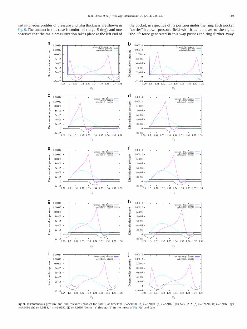
instantaneous profiles of pressure and film thickness are shown inFig. 9. The contact in this case is conformal (large-R ring), and oneobserves that the main pressurization takes place at the left end of
the pocket, irrespective of its position under the ring. Each pocket“carries” its own pressure field with it as it moves to the right.The lift force generated in this way pushes the ring further away
−2e−05
0
2e−05
4e−05
6e−05
8e−05
0.0001
0.00012
0.00014
1.29 1.3 1.31 1.32 1.33 1.34 1.35 1.36 1.37 1.38 1.29 1.3 1.31 1.32 1.33 1.34 1.35 1.36 1.37 1.38
Dim
ensi
onle
ss p
ress
ure
textured−filmthicknesstextured−pressure
untextured−pressure
x1 x1
1.29 1.3 1.31 1.32 1.33 1.34 1.35 1.36 1.37 1.38 1.29 1.3 1.31 1.32 1.33 1.34 1.35 1.36 1.37 1.38
x1 x1
1.29 1.3 1.31 1.32 1.33 1.34 1.35 1.36 1.37 1.38 1.29 1.3 1.31 1.32 1.33 1.34 1.35 1.36 1.37 1.38
x1 x1
1.29 1.3 1.31 1.32 1.33 1.34 1.35 1.36 1.37 1.38 1.29 1.3 1.31 1.32 1.33 1.34 1.35 1.36 1.37 1.38
x1 x1
1.29 1.3 1.31 1.32 1.33 1.34 1.35 1.36 1.37 1.38 1.29 1.3 1.31 1.32 1.33 1.34 1.35 1.36 1.37 1.38
x1 x1
Dim
ensi
onle
ss p
ress
ure
−2e−05
0
2e−05
4e−05
6e−05
8e−05
0.0001
0.00012
0.00014textured−filmthickness
textured−pressureuntextured−pressure
untextured − pressure
−2e−05
0
2e−05
4e−05
6e−05
8e−05
0.0001
0.00012
0.00014
Dim
ensi
onle
ss p
ress
ure
textured − film thicknesstextured − pressure
−2e−05
0
2e−05
4e−05
6e−05
8e−05
0.0001
0.00012
0.00014
Dim
ensi
onle
ss p
ress
ure
textured − film thicknesstextured − pressure
untextured − pressure
−2e−05
0
2e−05
4e−05
6e−05
8e−05
0.0001
0.00012
0.00014
Dim
ensi
onle
ss p
ress
ure
textured − film thicknesstextured − pressure
untextured − pressure
−2e−05
0
2e−05
4e−05
6e−05
8e−05
0.0001
0.00012
0.00014
Dim
ensi
onle
ss p
ress
ure
textured − film thicknesstextured − pressure
untextured − pressure
−2e−05
0
2e−05
4e−05
6e−05
8e−05
0.0001
0.00012
0.00014
Dim
ensi
onle
ss p
ress
ure
textured − film thicknesstextured − pressure
untextured − pressure
−2e−05
0
2e−05
4e−05
6e−05
8e−05
0.0001
0.00012
0.00014
Dim
ensi
onle
ss p
ress
ure
textured − film thicknesstextured − pressure
untextured − pressure
−2e−05
0
2e−05
4e−05
6e−05
8e−05
0.0001
0.00012
0.00014
Dim
ensi
onle
ss p
ress
ure
textured − film thicknesstextured − pressure
untextured − pressure
−2e−05
0
2e−05
4e−05
6e−05
8e−05
0.0001
0.00012
0.00014
Dim
ensi
onle
ss p
ress
ure
textured − film thicknesstextured − pressure
untextured − pressure
Fig. 9. Instantaneous pressure and film thickness profiles for Case II at times: (a) t¼5.9008, (b) t¼5.9104, (c) t¼5.9168, (d) t¼5.9232, (e) t¼5.9296, (f) t¼5.9360, (g)t¼5.9424, (h) t¼5.9488, (i) t¼5.9552, (j) t¼5.9616 (Points “a” through “j” in the insets of Fig. 7(c) and (d)).
H.M. Checo et al. / Tribology International 72 (2014) 131–142 139
from the liner, thus reducing the average friction force (dominatedby the Couette term proportional to 1=h).
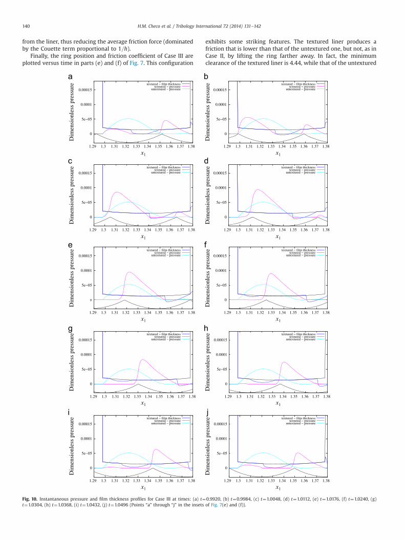
Finally, the ring position and friction coefficient of Case III areplotted versus time in parts (e) and (f) of Fig. 7. This configuration
exhibits some striking features. The textured liner produces afriction that is lower than that of the untextured one, but not, as inCase II, by lifting the ring farther away. In fact, the minimumclearance of the textured liner is 4.44, while that of the untextured
untextured − pressure
0
5e−05
0.0001
0.00015
1.29 1.3 1.31 1.32 1.33 1.34 1.35 1.36 1.37 1.38 1.29 1.3 1.31 1.32 1.33 1.34 1.35 1.36 1.37 1.38
1.29 1.3 1.31 1.32 1.33 1.34 1.35 1.36 1.37 1.38 1.29 1.3 1.31 1.32 1.33 1.34 1.35 1.36 1.37 1.38
1.29 1.3 1.31 1.32 1.33 1.34 1.35 1.36 1.37 1.38 1.29 1.3 1.31 1.32 1.33 1.34 1.35 1.36 1.37 1.38
1.29 1.3 1.31 1.32 1.33 1.34 1.35 1.36 1.37 1.38 1.29 1.3 1.31 1.32 1.33 1.34 1.35 1.36 1.37 1.38
1.29 1.3 1.31 1.32 1.33 1.34 1.35 1.36 1.37 1.38 1.29 1.3 1.31 1.32 1.33 1.34 1.35 1.36 1.37 1.38
Dim
ensi
onle
ss p
ress
ure textured − film thickness
textured − pressure
x1 x1
x1 x1
x1 x1
x1 x1
x1 x1
0
5e−05
0.0001
0.00015
textured − film thicknesstextured − pressure
untextured − pressure
0
5e−05
0.0001
0.00015
Dim
ensi
onle
ss p
ress
ure textured − film thickness
textured − pressureuntextured − pressure
0
5e−05
0.0001
0.00015
textured − film thicknesstextured − pressure
untextured − pressure
0
5e−05
0.0001
0.00015
Dim
ensi
onle
ss p
ress
ure textured − film thickness
textured − pressureuntextured − pressure
0
5e−05
0.0001
0.00015
textured − film thicknesstextured − pressure
untextured − pressure
0
5e−05
0.0001
0.00015
Dim
ensi
onle
ss p
ress
ure textured − film thickness
textured − pressureuntextured − pressure
0
5e−05
0.0001
0.00015
textured − film thicknesstextured − pressure
untextured − pressure
0
5e−05
0.0001
0.00015
Dim
ensi
onle
ss p
ress
ure
Dim
ensi
onle
ss p
ress
ure
Dim
ensi
onle
ss p
ress
ure
Dim
ensi
onle
ss p
ress
ure
Dim
ensi
onle
ss p
ress
ure
Dim
ensi
onle
ss p
ress
uretextured − film thickness
textured − pressureuntextured − pressure
0
5e−05
0.0001
0.00015
textured − film thicknesstextured − pressure
untextured − pressure
Fig. 10. Instantaneous pressure and film thickness profiles for Case III at times: (a) t¼0.9920, (b) t¼0.9984, (c) t¼1.0048, (d) t¼1.0112, (e) t¼1.0176, (f) t¼1.0240, (g)t¼1.0304, (h) t¼1.0368, (i) t¼1.0432, (j) t¼1.0496 (Points “a” through “j” in the insets of Fig. 7(e) and (f)).
H.M. Checo et al. / Tribology International 72 (2014) 131–142140
one it is 5.71. The friction coefficient, in turn, is lower for the texturedliner (0.0087) than for the untextured one (0.0101). The instantaneousprofiles of pressure and film thickness that are shown in Fig. 10 helpunderstand this apparent paradox. On the right half of each pocket,the diverging geometry generates a vast cavitated zone. In this zone,the saturation variable θ falls below θs thus making the Couettecontribution to the friction to vanish in this zone.
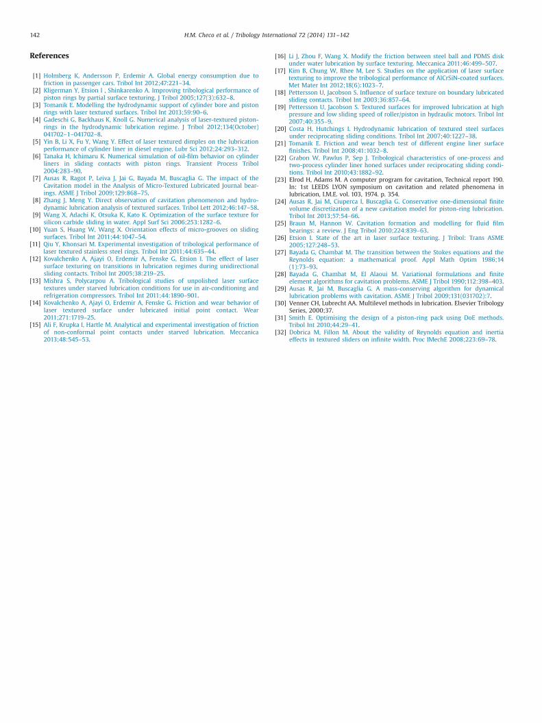
The pressure generation mechanism that takes place in close-packed square arrays of pockets (such as in Case III) of differentradii is shown in Fig. 12. There, the ring position is fixed atZ¼2.5 μ, and we examine the pressure field (along x2 ¼ per=2)at two different instants for 10-μm-deep pockets of radii 100, 200and 400 μ. It is clear from the picture that there is a pressurizedregion along the left part of each pocket, which acts as a texture-cell-level wedge. The pressurized region moves with the pocketbut is otherwise quite constant. The peak pressure and the load
carrying capacity increase with the pocket size, so that the optimaltexture is a close-packed square array of pockets approximatelythe size of the ring width. The optimal depth as suggested by ourstudy is 10 μ, though it is probably load-dependent.
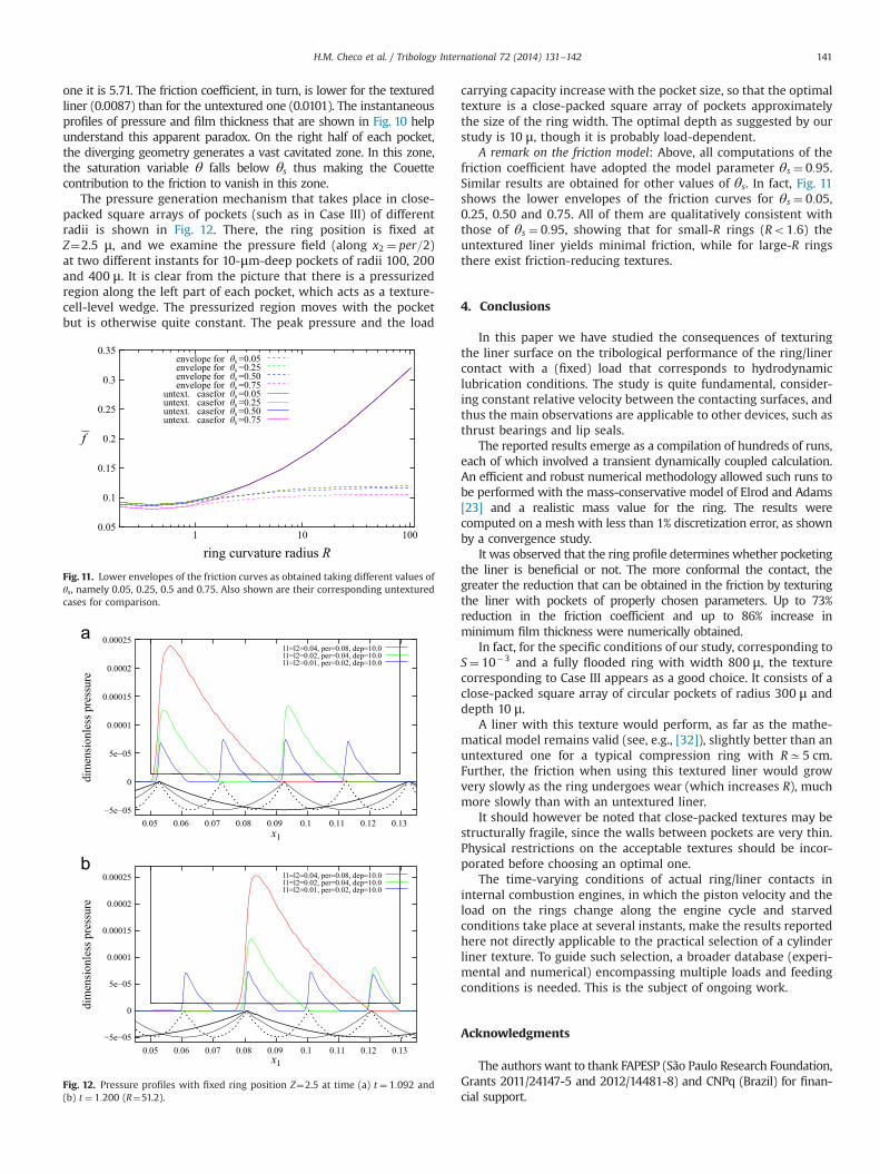
A remark on the friction model: Above, all computations of thefriction coefficient have adopted the model parameter θs ¼ 0:95.Similar results are obtained for other values of θs. In fact, Fig. 11shows the lower envelopes of the friction curves for θs ¼ 0:05,0.25, 0.50 and 0.75. All of them are qualitatively consistent withthose of θs ¼ 0:95, showing that for small-R rings (Ro1:6) theuntextured liner yields minimal friction, while for large-R ringsthere exist friction-reducing textures.
4. Conclusions
In this paper we have studied the consequences of texturingthe liner surface on the tribological performance of the ring/linercontact with a (fixed) load that corresponds to hydrodynamiclubrication conditions. The study is quite fundamental, consider-ing constant relative velocity between the contacting surfaces, andthus the main observations are applicable to other devices, such asthrust bearings and lip seals.
The reported results emerge as a compilation of hundreds of runs,each of which involved a transient dynamically coupled calculation.An efficient and robust numerical methodology allowed such runs tobe performed with the mass-conservative model of Elrod and Adams[23] and a realistic mass value for the ring. The results werecomputed on a mesh with less than 1% discretization error, as shownby a convergence study.
It was observed that the ring profile determines whether pocketingthe liner is beneficial or not. The more conformal the contact, thegreater the reduction that can be obtained in the friction by texturingthe liner with pockets of properly chosen parameters. Up to 73%reduction in the friction coefficient and up to 86% increase inminimum film thickness were numerically obtained.
In fact, for the specific conditions of our study, corresponding toS¼ 10�3 and a fully flooded ring with width 800 μ, the texturecorresponding to Case III appears as a good choice. It consists of aclose-packed square array of circular pockets of radius 300 μ anddepth 10 μ.
A liner with this texture would perform, as far as the mathe-matical model remains valid (see, e.g., [32]), slightly better than anuntextured one for a typical compression ring with RC5 cm.Further, the friction when using this textured liner would growvery slowly as the ring undergoes wear (which increases R), muchmore slowly than with an untextured liner.
It should however be noted that close-packed textures may bestructurally fragile, since the walls between pockets are very thin.Physical restrictions on the acceptable textures should be incor-porated before choosing an optimal one.
The time-varying conditions of actual ring/liner contacts ininternal combustion engines, in which the piston velocity and theload on the rings change along the engine cycle and starvedconditions take place at several instants, make the results reportedhere not directly applicable to the practical selection of a cylinderliner texture. To guide such selection, a broader database (experi-mental and numerical) encompassing multiple loads and feedingconditions is needed. This is the subject of ongoing work.
Acknowledgments
The authors want to thank FAPESP (São Paulo Research Foundation,Grants 2011/24147-5 and 2012/14481-8) and CNPq (Brazil) for finan-cial support.
0.05
0.1
0.15
0.2
0.25
0.3
0.35
100101
envelope for θs =0.05envelope for θs =0.25envelope for θs =0.50envelope for θs =0.75
untext. casefor θs =0.05untext. casefor θs =0.25untext. casefor θs =0.50untext. casefor θs =0.75
ring curvature radius R
f
Fig. 11. Lower envelopes of the friction curves as obtained taking different values ofθs, namely 0.05, 0.25, 0.5 and 0.75. Also shown are their corresponding untexturedcases for comparison.
−5e−05
0
5e−05
0.0001
0.00015
0.0002
0.00025
dim
ensi
onle
ss p
ress
ure
l1=l2=0.04, per=0.08, dep=10.0l1=l2=0.02, per=0.04, dep=10.0l1=l2=0.01, per=0.02, dep=10.0
x1
x1
−5e−05
0
5e−05
0.0001
0.00015
0.0002
0.00025
0.05 0.06 0.07 0.08 0.09 0.1 0.11 0.12 0.13
0.05 0.06 0.07 0.08 0.09 0.1 0.11 0.12 0.13
dim
ensi
onle
ss p
ress
ure
l1=l2=0.04, per=0.08, dep=10.0l1=l2=0.02, per=0.04, dep=10.0l1=l2=0.01, per=0.02, dep=10.0
Fig. 12. Pressure profiles with fixed ring position Z¼2.5 at time (a) t ¼ 1:092 and(b) t ¼ 1:200 (R¼51.2).
H.M. Checo et al. / Tribology International 72 (2014) 131–142 141
References
[1] Holmberg K, Andersson P, Erdemir A. Global energy consumption due tofriction in passenger cars. Tribol Int 2012;47:221–34.
[2] Kligerman Y, Etsion I , Shinkarenko A. Improving tribological performance ofpiston rings by partial surface texturing. J Tribol 2005;127(3):632–8.
[3] Tomanik E. Modelling the hydrodynamic support of cylinder bore and pistonrings with laser textured surfaces. Tribol Int 2013;59:90–6.
[4] Gadeschi G, Backhaus K, Knoll G. Numerical analysis of laser-textured piston-rings in the hydrodynamic lubrication regime. J Tribol 2012;134(October)041702–1–041702–8.
[5] Yin B, Li X, Fu Y, Wang Y. Effect of laser textured dimples on the lubricationperformance of cylinder liner in diesel engine. Lubr Sci 2012;24:293–312.
[6] Tanaka H, Ichimaru K. Numerical simulation of oil-film behavior on cylinderliners in sliding contacts with piston rings. Transient Process Tribol2004:283–90.
[7] Ausas R, Ragot P, Leiva J, Jai G, Bayada M, Buscaglia G. The impact of theCavitation model in the Analysis of Micro-Textured Lubricated Journal bear-ings. ASME J Tribol 2009;129:868–75.
[8] Zhang J, Meng Y. Direct observation of cavitation phenomenon and hydro-dynamic lubrication analysis of textured surfaces. Tribol Lett 2012;46:147–58.
[9] Wang X, Adachi K, Otsuka K, Kato K. Optimization of the surface texture forsilicon carbide sliding in water. Appl Surf Sci 2006;253:1282–6.
[10] Yuan S, Huang W, Wang X. Orientation effects of micro-grooves on slidingsurfaces. Tribol Int 2011;44:1047–54.
[11] Qiu Y, Khonsari M. Experimental investigation of tribological performance oflaser textured stainless steel rings. Tribol Int 2011;44:635–44.
[12] Kovalchenko A, Ajayi O, Erdemir A, Fenske G, Etsion I. The effect of lasersurface texturing on transitions in lubrication regimes during unidirectionalsliding contacts. Tribol Int 2005;38:219–25.
[13] Mishra S, Polycarpou A. Tribological studies of unpolished laser surfacetextures under starved lubrication conditions for use in air-conditioning andrefrigeration compressors. Tribol Int 2011;44:1890–901.
[14] Kovalchenko A, Ajayi O, Erdemir A, Fenske G. Friction and wear behavior oflaser textured surface under lubricated initial point contact. Wear2011;271:1719–25.
[15] Ali F, Krupka I, Hartle M. Analytical and experimental investigation of frictionof non-conformal point contacts under starved lubrication. Meccanica2013;48:545–53.
[16] Li J, Zhou F, Wang X. Modify the friction between steel ball and PDMS diskunder water lubrication by surface texturing. Meccanica 2011;46:499–507.
[17] Kim B, Chung W, Rhee M, Lee S. Studies on the application of laser surfacetexturing to improve the tribological performance of AlCrSiN-coated surfaces.Met Mater Int 2012;18(6):1023–7.
[18] Pettersson U, Jacobson S. Influence of surface texture on boundary lubricatedsliding contacts. Tribol Int 2003;36:857–64.
[19] Pettersson U, Jacobson S. Textured surfaces for improved lubrication at highpressure and low sliding speed of roller/piston in hydraulic motors. Tribol Int2007;40:355–9.
[20] Costa H, Hutchings I. Hydrodynamic lubrication of textured steel surfacesunder reciprocating sliding conditions. Tribol Int 2007;40:1227–38.
[21] Tomanik E. Friction and wear bench test of different engine liner surfacefinishes. Tribol Int 2008;41:1032–8.
[22] Grabon W, Pawlus P, Sep J. Tribological characteristics of one-process andtwo-process cylinder liner honed surfaces under reciprocating sliding condi-tions. Tribol Int 2010;43:1882–92.
[23] Elrod H, Adams M. A computer program for cavitation, Technical report 190.In: 1st LEEDS LYON symposium on cavitation and related phenomena inlubrication, I.M.E. vol. 103, 1974. p. 354.
[24] Ausas R, Jai M, Ciuperca I, Buscaglia G. Conservative one-dimensional finitevolume discretization of a new cavitation model for piston-ring lubrication.Tribol Int 2013;57:54–66.
[25] Braun M, Hannon W. Cavitation formation and modelling for fluid filmbearings: a review. J Eng Tribol 2010;224:839–63.
[26] Etsion I. State of the art in laser surface texturing. J Tribol: Trans ASME2005;127:248–53.
[27] Bayada G, Chambat M. The transition between the Stokes equations and theReynolds equation: a mathematical proof. Appl Math Optim 1986;14(1):73–93.
[28] Bayada G, Chambat M, El Alaoui M. Variational formulations and finiteelement algorithms for cavitation problems. ASME J Tribol 1990;112:398–403.
[29] Ausas R, Jai M, Buscaglia G. A mass-conserving algorithm for dynamicallubrication problems with cavitation. ASME J Tribol 2009;131(031702):7.
[30] Venner CH, Lubrecht AA. Multilevel methods in lubrication. Elsevier TribologySeries, 2000;37.
[31] Smith E. Optimising the design of a piston-ring pack using DoE methods.Tribol Int 2010;44:29–41.
[32] Dobrica M, Fillon M. About the validity of Reynolds equation and inertiaeffects in textured sliders on infinite width. Proc IMechE 2008;223:69–78.
H.M. Checo et al. / Tribology International 72 (2014) 131–142142