Embed Size (px)
Citation preview

Moving Interface Problems—Complex Flows
Moving Interface Problems:Methods & Applications
Tutorial Lecture IV
Grétar TryggvasonWorcester Polytechnic Institute
Moving Interface Problems and Applications in Fluid Dynamics
Singapore National University, 2007

Moving Interface Problems—Complex Flows
Outline
Flows with phase changeSolidificationBoiling
Electrohydrodynamics
Flows with topology changesRegime changes in bubbly flowsAtomization and sprays
Outlook
Phase Change
Moving Interface Problems—Complex Flows
The phase change between liquid and solid or betweenliquid and vapor is the critical step in the processing ofmost material as well as in energy generation.Computations will make it possible to predict the smallscale evolution of systems undergoing phase changefrom first principles.
To simulate such flows, it is necessary to solve theenergy equation for the temperature distribution and toaccount for the change of phase at the phase boundary.
Phase Change

Moving Interface Problems—Complex Flows
In addition to solving the energy equation and includingthe phase change, we must
• Account for volume expansion at the interface for boiling
• Accommodate a zero velocity field in the solid, for the solidification problem.
In reality there is a slight volume change for thesolidification as well, but this can usually be neglected.
Phase Change

Moving Interface Problems—Complex Flows
Formation ofMicrostructure
duringSolidification
Moving Interface Problems—Complex FlowsPhase Change
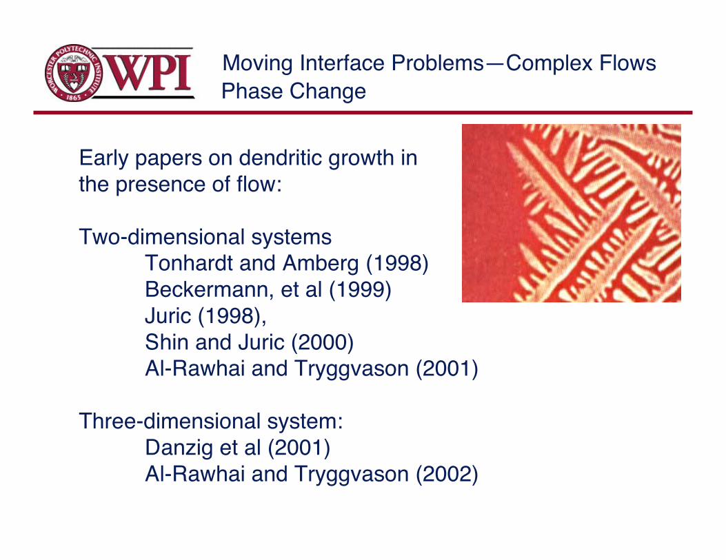
Early papers on dendritic growth inthe presence of flow:
Two-dimensional systemsTonhardt and Amberg (1998)Beckermann, et al (1999)
Juric (1998),Shin and Juric (2000)Al-Rawhai and Tryggvason (2001)
Three-dimensional system:Danzig et al (2001)Al-Rawhai and Tryggvason (2002)

Moving Interface Problems—Complex Flows
!
"cT
"t+# $ucT =# $ k#T + q%& (x ' x f )dA
Tf = Tm (1+(
L+L)
q = LVn
dx f
dt=Vnn
Pure material
• D. Juric and G. Tryggvason, "A Front Tracking Method for Dentritic Solidification."J. Comput. Phys. 123, 127-148, (1996).
• N. Al-Rawahi and G. Tryggvason. Computations of the growth of dendrites in thepresence of flow. Part I-Two-dimensional Flow. J. Comput. Phys. 180, 471–496(2002)
• N. Al-Rawahi and G. Tryggvason. “Numerical simulation of dendritic solidificationwith convection: Three-dimensional flow.” Journal of Computational Physics. 194(2004) 677–696
Solidification

Moving Interface Problems—Complex Flows
(C, D) =(c1/ k, kD
1) in the solid
(c2,D
2) in the liquid
! " #
k = c1/ c
2
$C
$t=% &D%T + s'( (x ) x f )dA
s = C(1 ) k)Vn
Tf = Tm (1+*
L) Cm)
m: slope of liquidus line
Alloy
Solidification
In addition to the energy equation, wemust solve a species concentrationequation

Moving Interface Problems—Complex Flows
Compute the heat source at the interface
T+
T-
Ts
(x0,y0)
(x1,y1)
!
˙ q = k"T
"n
#
$ %
l
& k"T
"n
#
$ %
s
Solidification
Originally we found theheat source iterativelysuch that the interfacetemperature matchedthe target value.Currently we use“normal probes,”following Udaykumar etal.
Moving Interface Problems—Complex Flows
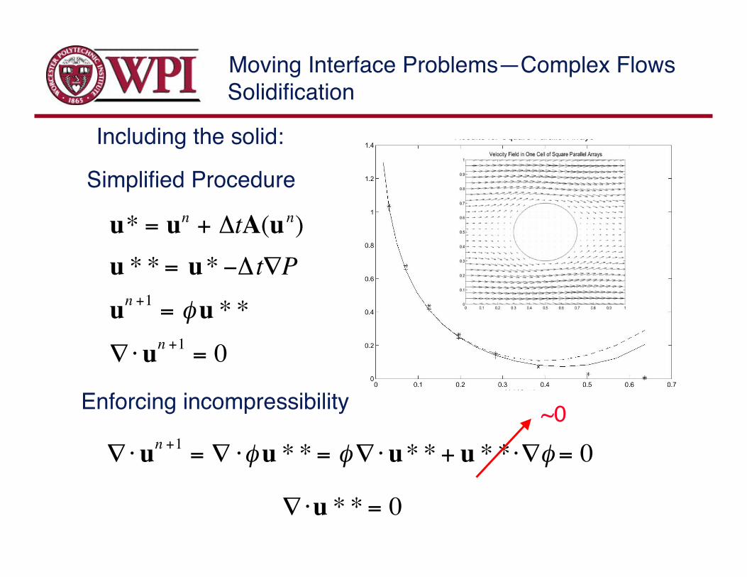
u* = un + !tA(un)
u * * = u* "!t#P
un +1
= $u * *
#%un +1
= 0
!"un +1
= ! "#u * * = #!"u* * + u * * "!# = 0
!"u * * = 0
Including the solid:
Simplified Procedure
Enforcing incompressibility ~0
Solidification

Moving Interface Problems—Complex Flows
Dendrite growing in auniform flow
401 by 401grid
Anisotropy=0.4
St =c(T! " Tm )
L= "0.3
Re =#UZ
µ= 600
Solidification

Moving Interface Problems—Complex Flows
Dendrite growing in auniform flow
401 by 401grid
Anisotropy=0.4
St =c(T! " Tm )
L= "0.3
Re =#UZ
µ= 600
Solidification
Moving Interface Problems—Complex Flows
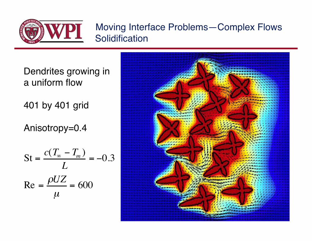
Dendrites growing ina uniform flow
401 by 401 grid
Anisotropy=0.4
St =c(T! " Tm )
L= "0.3
Re =#UZ
µ= 600
Solidification
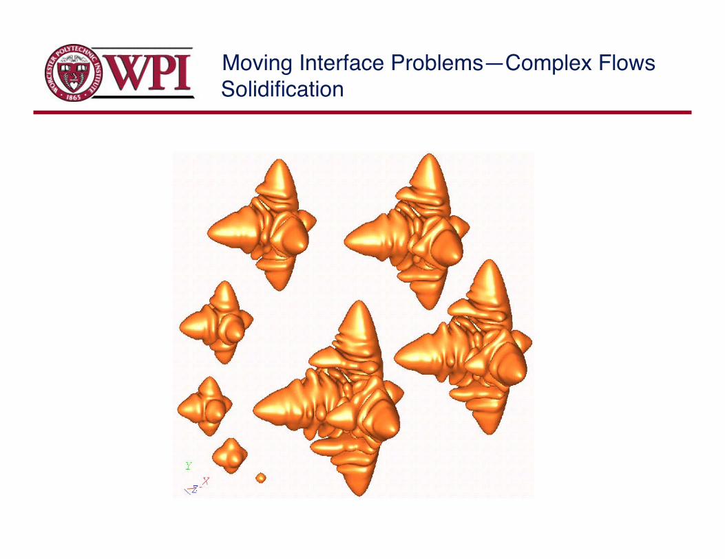
Moving Interface Problems—Complex FlowsSolidification
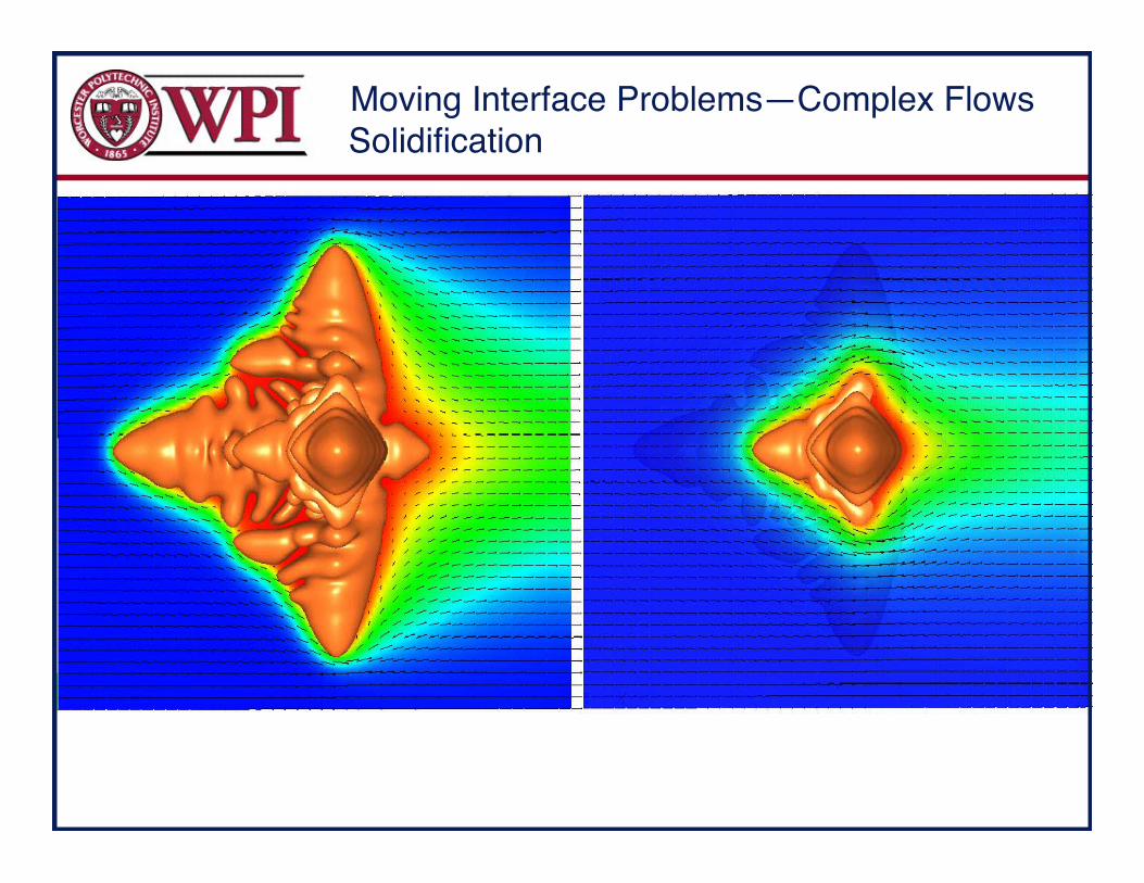
Moving Interface Problems—Complex FlowsSolidification

Moving Interface Problems—Complex Flows
Velocity of the tip of the arms
0 0.5 1 1.5 2 2.5 30
0.2
0.4
0.6
0.8
1
1.2
1.4
1.6
1.8
2
Time
Tip velocity
Upstream tip velocity with Pef=0.002
Downstream tip velocity with Pef=0.002
Perpendicular tip velocity with Pef=0.002
Upstream tip velocity with Pef=0.006
Downstream tip velocity with Pef=0.006
Perpendicular tip velocity with Pef=0.006
Tip velocity with Pef=0
x106
x10-3
Solidification

Moving Interface Problems—Complex Flows
Key challenges include:•The extension of the numerical methods to alloys•Inclusion of more complex interfacial effects•The use of simulations to predict microstructure offully solidified materials and the bulk properties ofthe material•More complex processes, such as solidification ofstirred melts
Solidification
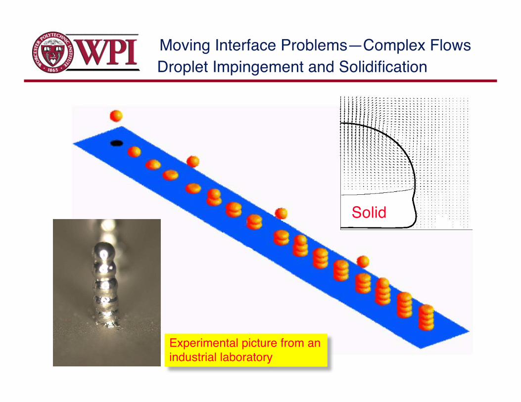
Moving Interface Problems—Complex FlowsDroplet Impingement and Solidification
Solid
Experimental picture from anindustrial laboratory

Moving Interface Problems—Complex Flows
Simulations ofBoiling Flows
Moving Interface Problems—Complex Flows
Early papers on boiling
Juric and Tryggvason (1998)Son and Dhir (1998)Son, Ramanujapu, and Dhir (2002)Welch and Wilson (2000)Song and Juric (2002)Esmaeeli and Tryggvason (2002)Kunugi et al., (2001,2002)
Boiling Flows

Moving Interface Problems—Complex Flows
!
"cT
"t+# $ u T =# $ k#T + q%& (x ' x f )dA
Tf :
q = L(V ' u ) $n
dx f
dt= Vnn+ u
# $ u =1
(
D(
Dt
Mass conservation
Energy equation
Thermodynamic
Velocity of bdryHeat source
Modified Clausius-Clapeyron eq.
D. Juric and G. Tryggvason. Computations of Boiling Flows. Int’l. J.Multiphase Flow. 24 (1998), 387-410.
A. Esmaeeli and G. Tryggvason. Computations of Explosive Boiling inMicrogravity. J. Scient. Comput. 19 (2003), 163-182
Boiling Flows

Moving Interface Problems—Complex Flows
Vn
ug
ul
Computing the volume source
!
˙ m = "l
ul#V
n( ) = "v
uv#V
n( )
Volume expansion:
!
uv" u
l= ˙ m
1
#v
"1
#l
$
% &
'
( )
!
Vn
=1
2u
v+ u
l( ) "˙ m
2
1
#v
+1
#l
$
% &
'
( )
Normal velocitySource term
!
" #u =˙ q
L
1
$v
%1
$l
&
' (
)
* + , x % x f( )ds-
Boiling Flows
Moving Interface Problems—Complex FlowsBoiling Flows
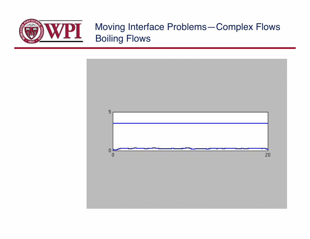
Moving Interface Problems—Complex Flows
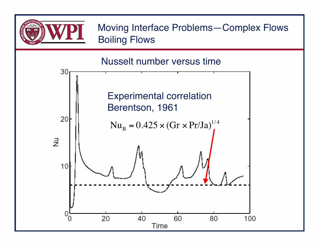
Nusselt number versus time
Experimental correlationBerentson, 1961
!
NuB = 0.425 " (Gr "Pr/Ja)1/ 4
Boiling Flows

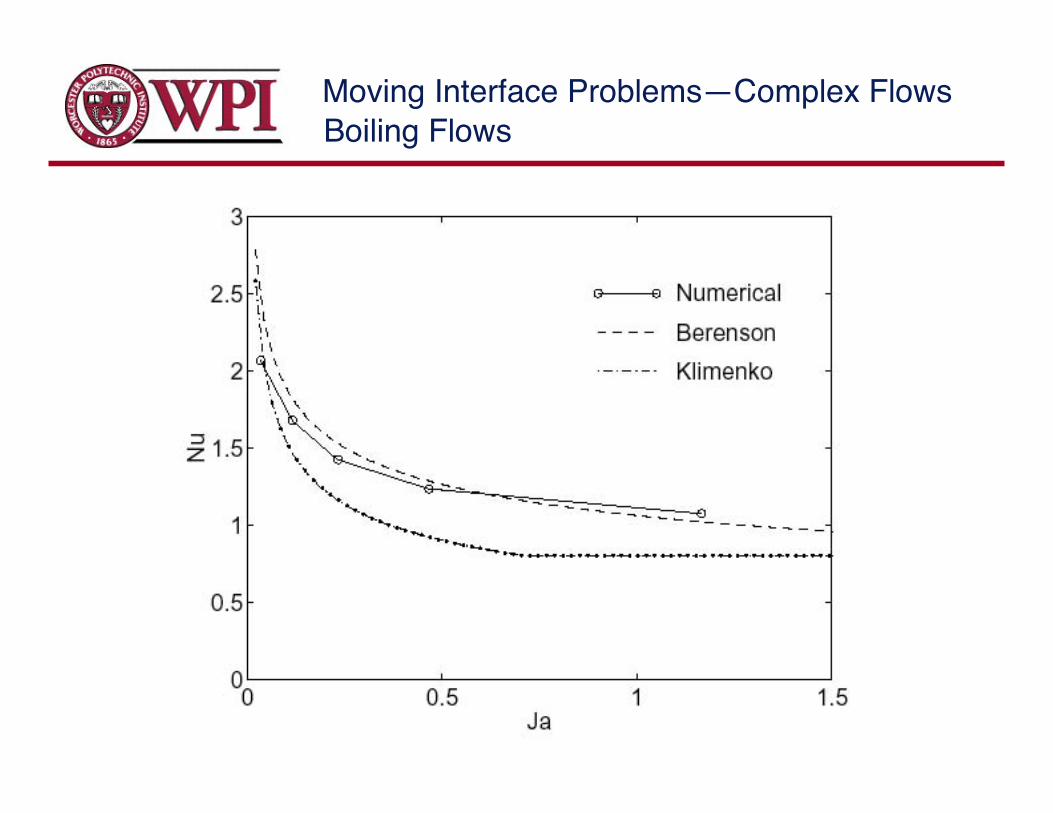
Moving Interface Problems—Complex Flows
The effect ofthe Jacobinumber onthe boiling fornear criticalfilm boiling
Ja=0.035
Ja=0.117
Ja=0.234
Ja=0.468
Ja=1.167
Boiling Flows
Moving Interface Problems—Complex FlowsBoiling Flows
Moving Interface Problems—Complex Flows
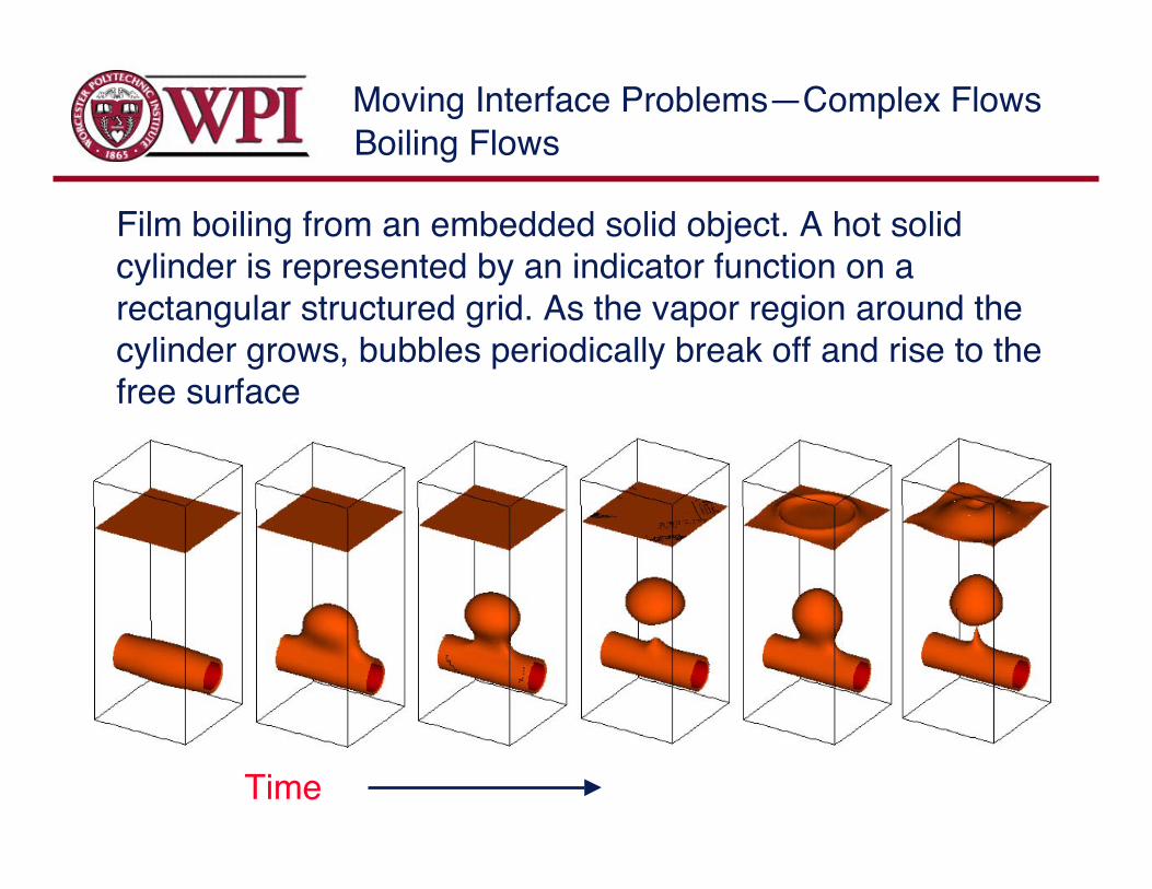
Film boiling from an embedded solid object. A hot solidcylinder is represented by an indicator function on arectangular structured grid. As the vapor region around thecylinder grows, bubbles periodically break off and rise to thefree surface
Time
Boiling Flows
Moving Interface Problems—Complex Flows
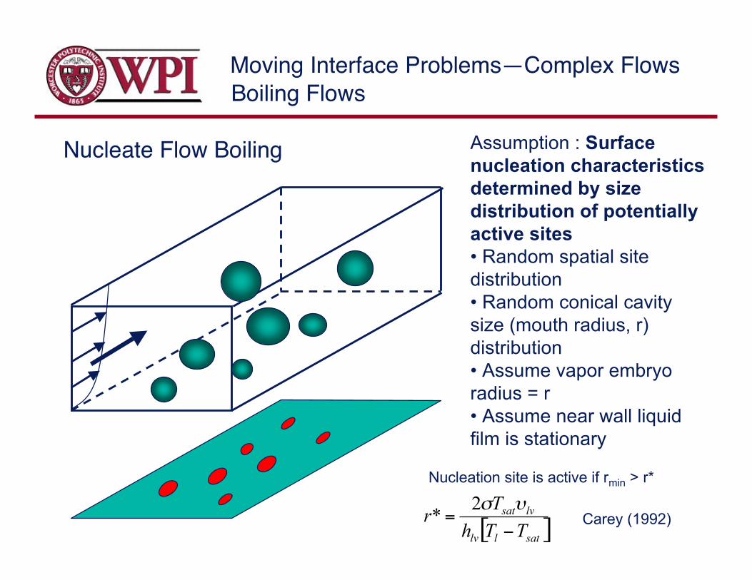
Nucleate Flow Boiling Assumption : Surfacenucleation characteristicsdetermined by sizedistribution of potentiallyactive sites• Random spatial sitedistribution• Random conical cavitysize (mouth radius, r)distribution• Assume vapor embryoradius = r• Assume near wall liquidfilm is stationary
Nucleation site is active if rmin > r*
[ ]satllv
lvsat
TTh
Tr
!=
"#2* Carey (1992)
Boiling Flows
Moving Interface Problems—Complex Flows
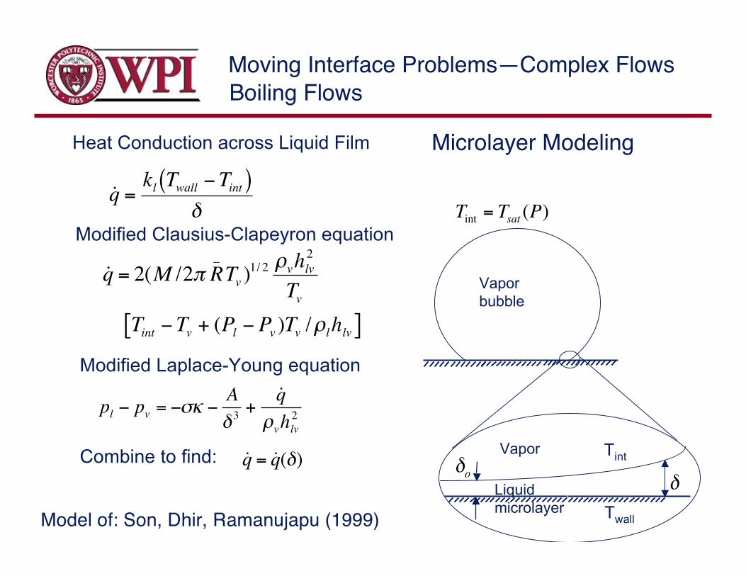
Microlayer Modeling
Model of: Son, Dhir, Ramanujapu (1999)
!
˙ q =kl Twall "Tint( )
#
!
˙ q = 2(M /2" R_
Tv )1/ 2 #vhlv
2
Tv
Tint $Tv + (Pl $ Pv )Tv /#lhlv[ ]
!
pl " pv = "#$ "A
% 3+
˙ q
&vhlv
2
Heat Conduction across Liquid Film
Modified Clausius-Clapeyron equation
Modified Laplace-Young equation
!
Tint = Tsat(P)
Combine to find:
!
˙ q = ˙ q (")
Vaporbubble
Liquidmicrolayer
!
Vapor Tint
Twall
!
"o
Boiling Flows
Moving Interface Problems—Complex Flows
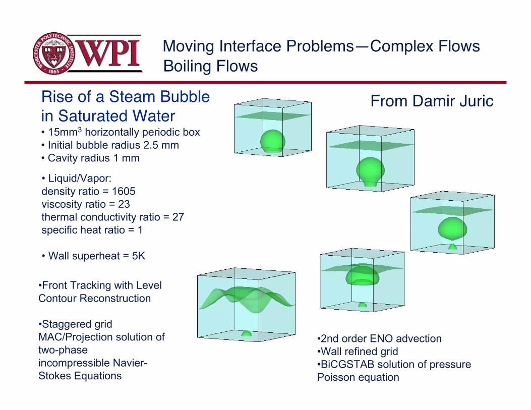
•Front Tracking with LevelContour Reconstruction
•Staggered gridMAC/Projection solution oftwo-phaseincompressible Navier-Stokes Equations
•2nd order ENO advection•Wall refined grid•BiCGSTAB solution of pressurePoisson equation
• Liquid/Vapor:density ratio = 1605viscosity ratio = 23thermal conductivity ratio = 27specific heat ratio = 1
• Wall superheat = 5K
• 15mm3 horizontally periodic box• Initial bubble radius 2.5 mm• Cavity radius 1 mm
From Damir Juric
Boiling Flows
Rise of a Steam Bubblein Saturated Water

Moving Interface Problems—Complex Flows
Water at 1atm, Tsat=373.15K; liquid/vapor density ratio=1605;viscosity ratio=23; thermal conductivity ratio=27; specific heat ratio=1;domain size: 10.5x10.5x15.75 mm; Wall superheat: 18K40x40x60 grid resolution
Moving Interface Problems—Complex Flows
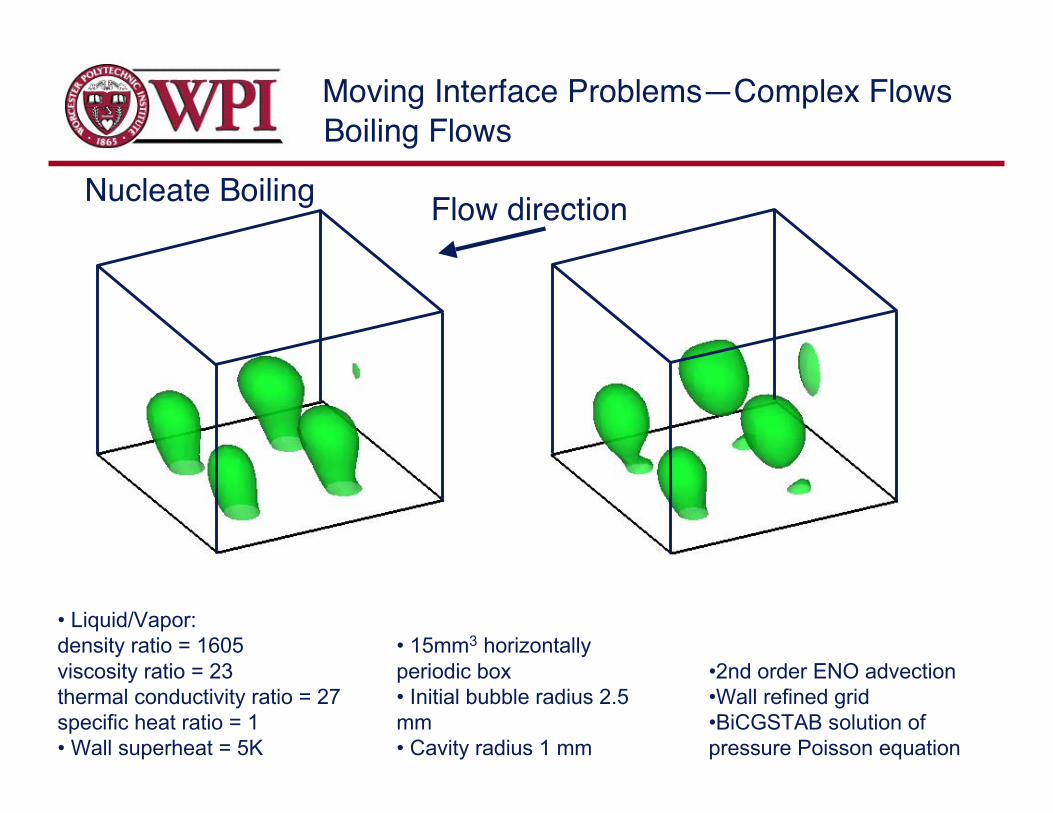
Flow directionNucleate Boiling
• Liquid/Vapor:density ratio = 1605viscosity ratio = 23thermal conductivity ratio = 27specific heat ratio = 1• Wall superheat = 5K
• 15mm3 horizontallyperiodic box• Initial bubble radius 2.5mm• Cavity radius 1 mm
•2nd order ENO advection•Wall refined grid•BiCGSTAB solution ofpressure Poisson equation
Boiling Flows

Moving Interface Problems—Complex Flows
There appears to be no significant technicalobstacles for conducting large scale simulationsof nucleate flow boiling—however, somedevelopment works still needs to be done!
Such simulations should allow us to• Assess the accuracy of the assumptions madein the modeling of the microlayer• Use the simulations to make predictions aboutboiling under conditions where experiments aredifficult or do not yield the necessary data.
Boiling Flows
Moving Interface Problems—Complex Flows
Electrohydrodynamicsof Droplet Suspensions
Moving Interface Problems—Complex Flows
Electrostatic fields are known to have strong influence onmultiphase flows:
Breakup of jets and drops
Phase distribution in suspensions
Here, we examine the effect of electrostatic fields on asuspension of drops in channel flows by direct numericalsimulations.
Electrohydrodynamics
For fluids with small but finite conductivity, Taylor and Melcher(1969) proposed the “leaky dielectric” model. This modelallows both normal and tangential electrostatic forces on a twofluid interface.
Moving Interface Problems—Complex Flows
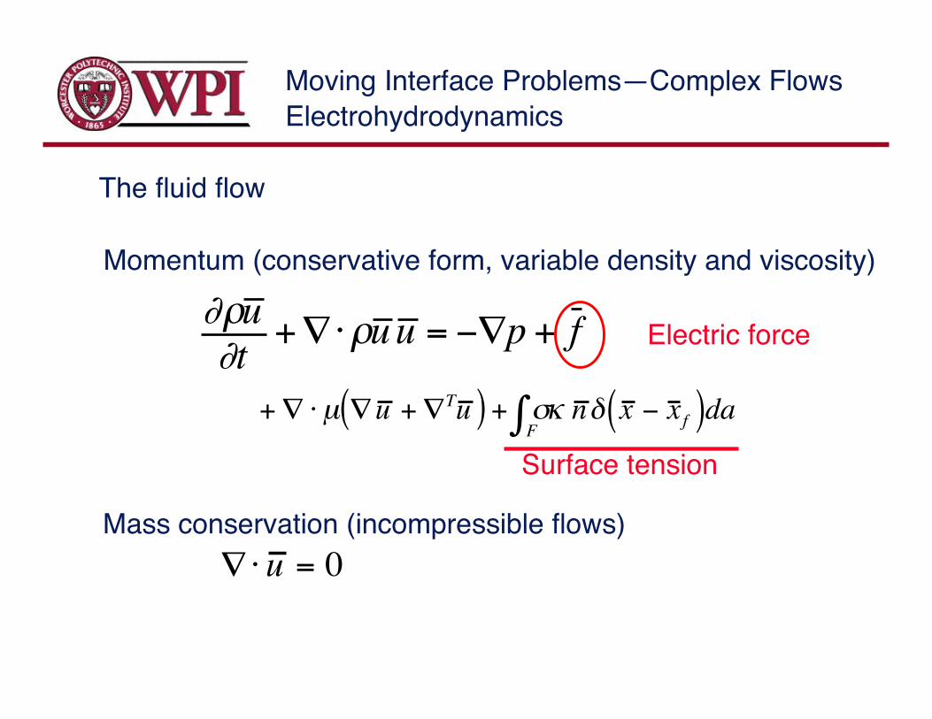
!"u
!t+#$"u u = %#p + f
+# $µ #u +#Tu ( ) + &F' ( n ) x % x f( )da
!" u = 0
Momentum (conservative form, variable density and viscosity)
Mass conservation (incompressible flows)
The fluid flow
Surface tension
Electric force
Electrohydrodynamics
Moving Interface Problems—Complex Flows
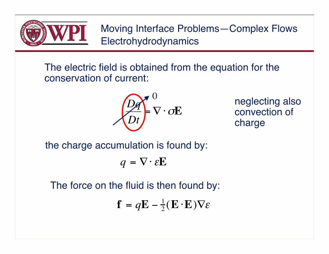
!
Dq
Dt=" #$E
f = qE ! 1
2(E "E)#$
q = !" #E
The electric field is obtained from the equation for theconservation of current:
the charge accumulation is found by:
The force on the fluid is then found by:
0 neglecting alsoconvection ofcharge
Electrohydrodynamics
Moving Interface Problems—Complex Flows
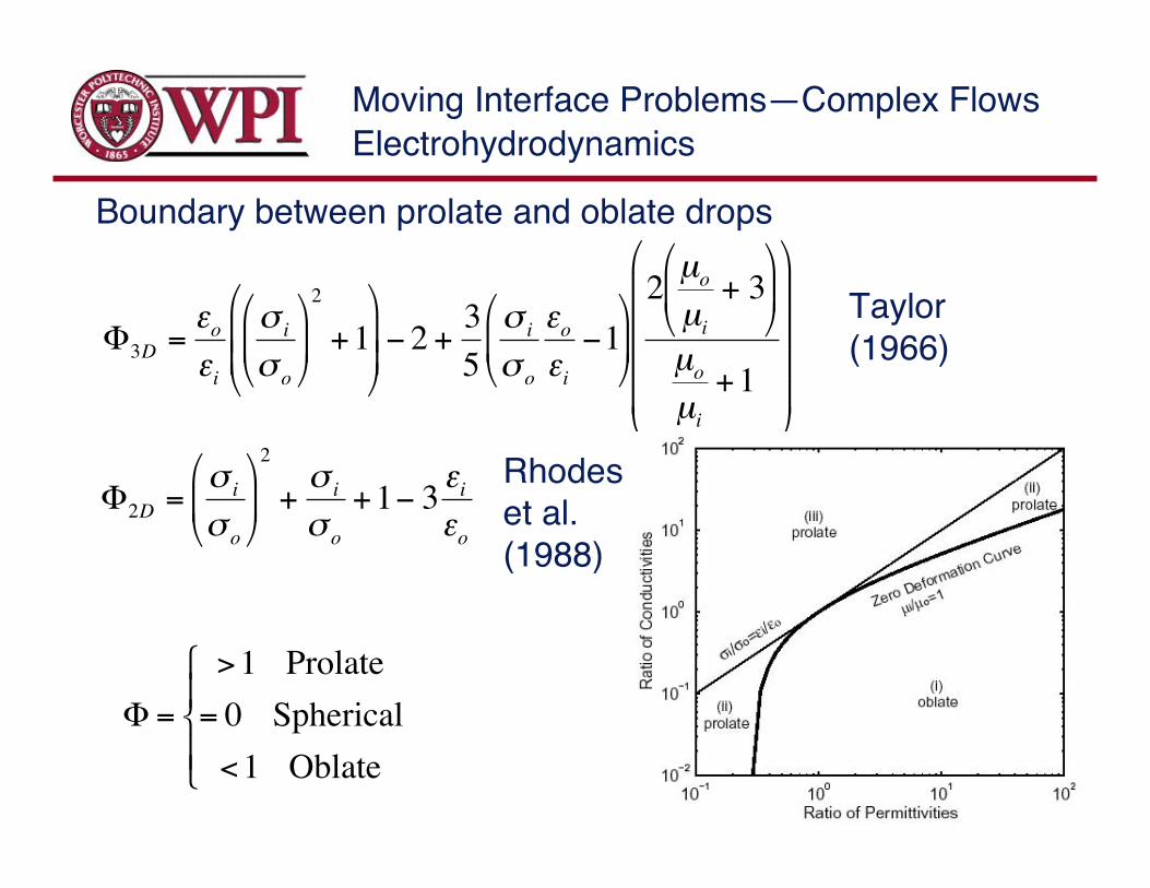
!
"3D
=#o
#i
$i
$o
%
& '
(
) *
2
+1
%
&
' '
(
)
* * + 2 +
3
5
$i
$o
#o
#i
+1%
& '
(
) *
2µo
µi
+ 3%
& '
(
) *
µo
µi
+1
%
&
' ' ' '
(
)
* * * *
!
"2D
=#i
#o
$
% &
'
( )
2
+#i
#o
+1* 3+i
+o
Boundary between prolate and oblate drops
Taylor(1966)
!
" =
>1 Prolate
= 0 Spherical
<1 Oblate
#
$ %
& %
Rhodeset al.(1988)
Electrohydrodynamics
Moving Interface Problems—Complex Flows
(b)
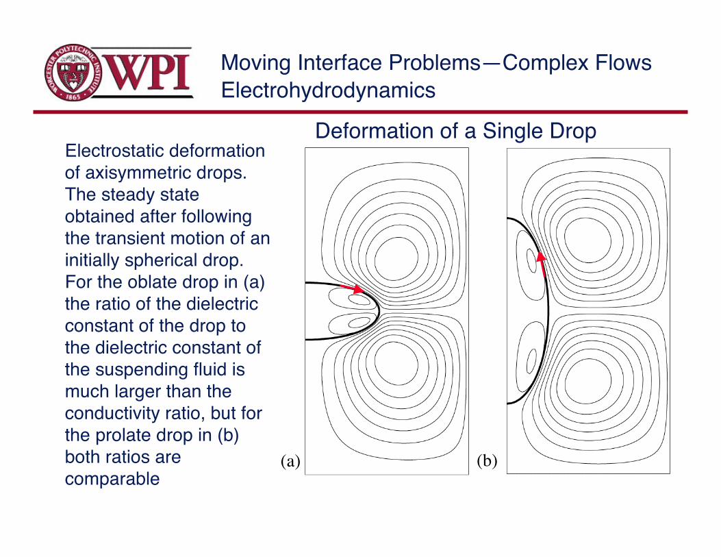
Electrostatic deformationof axisymmetric drops.The steady stateobtained after followingthe transient motion of aninitially spherical drop.For the oblate drop in (a)the ratio of the dielectricconstant of the drop tothe dielectric constant ofthe suspending fluid ismuch larger than theconductivity ratio, but forthe prolate drop in (b)both ratios arecomparable
(a)
Deformation of a Single Drop
Electrohydrodynamics
Moving Interface Problems—Complex Flows
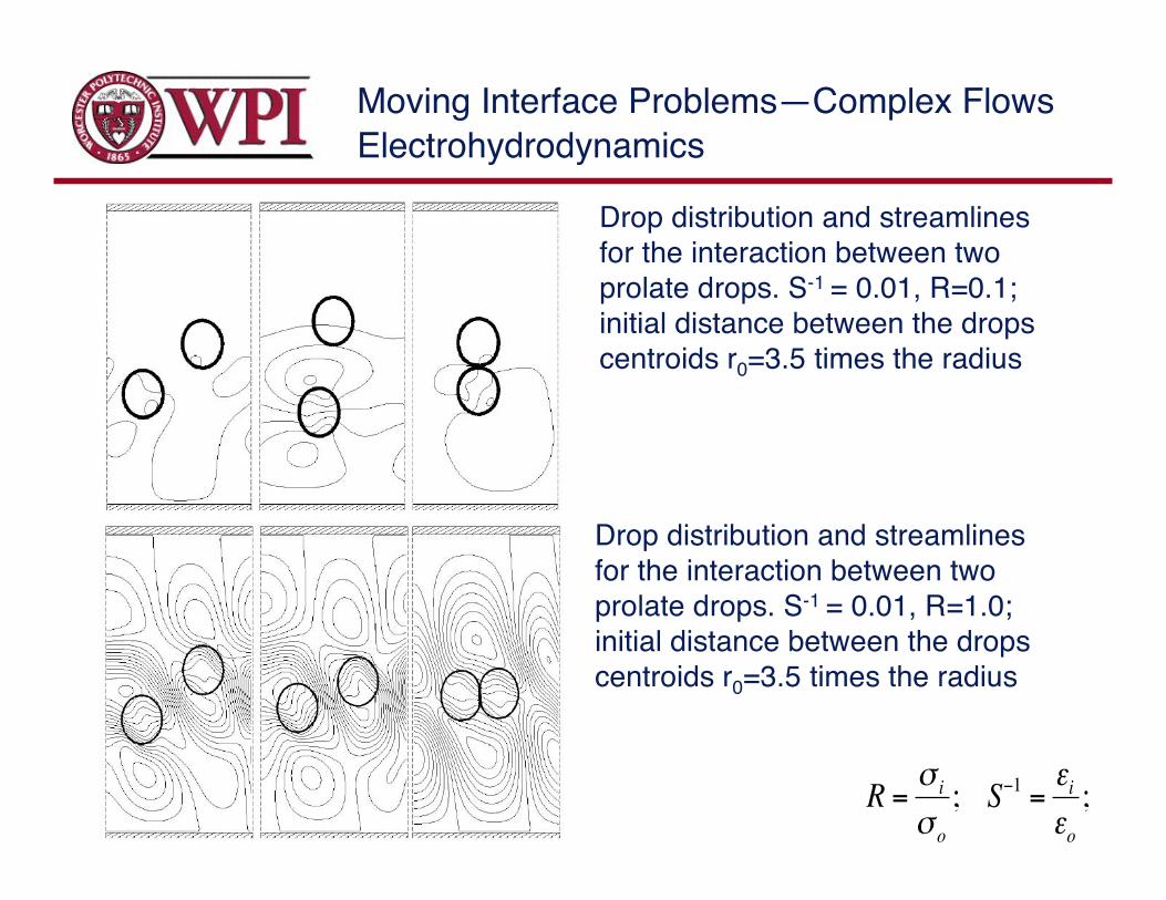
Drop distribution and streamlinesfor the interaction between twoprolate drops. S-1 = 0.01, R=0.1;initial distance between the dropscentroids r0=3.5 times the radius
Drop distribution and streamlinesfor the interaction between twoprolate drops. S-1 = 0.01, R=1.0;initial distance between the dropscentroids r0=3.5 times the radius
!
R ="i
"o
; S#1
=$i
$o
;
Electrohydrodynamics
Moving Interface Problems—Complex Flows
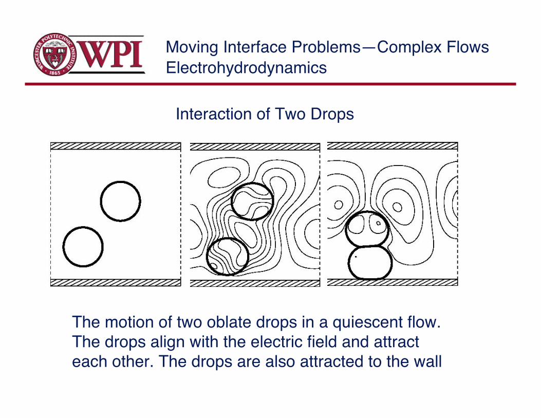
The motion of two oblate drops in a quiescent flow.The drops align with the electric field and attracteach other. The drops are also attracted to the wall
Interaction of Two Drops
Electrohydrodynamics
Moving Interface Problems—Complex FlowsElectrohydrodynamics
Moving Interface Problems—Complex Flows
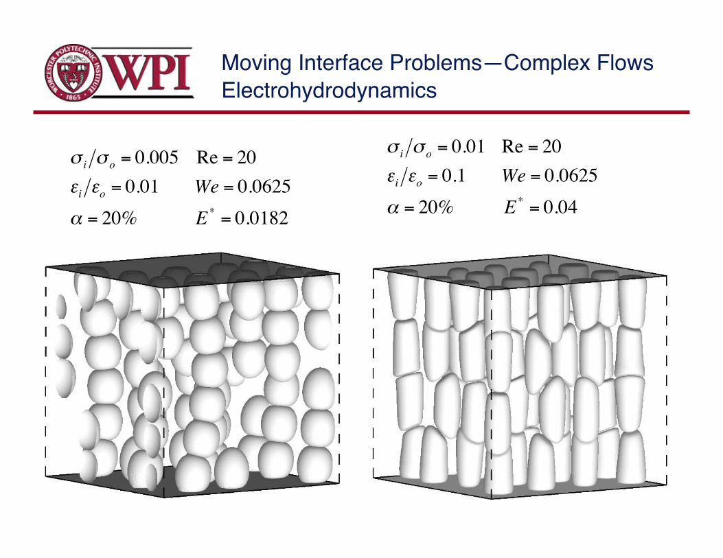
!
"i"o
= 0.005 Re = 20
#i#o
= 0.01 We = 0.0625
$ = 20% E*
= 0.0182
!
"i"o
= 0.01 Re = 20
#i#o
= 0.1 We = 0.0625
$ = 20% E*
= 0.04
Electrohydrodynamics
Moving Interface Problems—Complex Flows
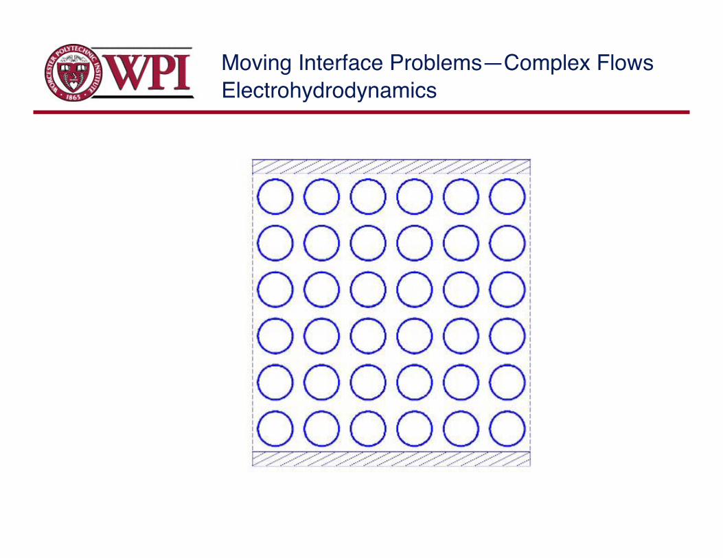
The interaction of many drops in channels, with andwithout flow has been examined.
Oblate drops always fibrate as the electrohydro-dynamically induced fluid motion works with the electricinteractions to line up the drops
Fluid shear breaks up the fibers, depositing them on thewalls for intermediate flow rate and keeping them insuspension for high enough flow rates
Prolate drops exhibit more complex interaction and formadditional structures
Electrohydrodynamics

Moving Interface Problems—Complex Flows
The instability of a thin film:
Electrohydrodynamics
The interface and thevelocity field at time zeroand three subsequenttimes for S=1 and R=100.
Moving Interface Problems—Complex Flows
Coalescence induced flowregime transitions
Moving Interface Problems—Complex Flows
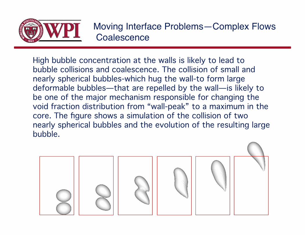
High bubble concentration at the walls is likely to lead tobubble collisions and coalescence. The collision of small andnearly spherical bubbles-which hug the wall-to form largedeformable bubbles—that are repelled by the wall—is likely tobe one of the major mechanism responsible for changing thevoid fraction distribution from “wall-peak” to a maximum in thecore. The figure shows a simulation of the collision of twonearly spherical bubbles and the evolution of the resulting largebubble.
Coalescence

Moving Interface Problems—Complex FlowsFlow regime changes
Coalescence induced flow regime transitions in a laminar bubbly channelflow: The figure shows a preliminary two-dimensional simulation of thetransition from a wall peaked distribution of many bubbles to a single largeslug in the channels center.
Moving Interface Problems—Complex Flows
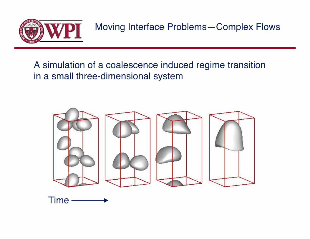
A simulation of a coalescence induced regime transitionin a small three-dimensional system
Time
Moving Interface Problems—Complex Flows
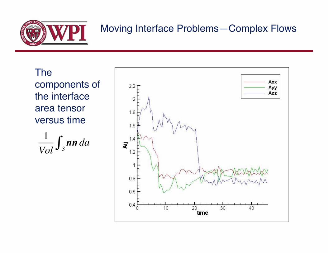
!
1
Volnnda
S"
Thecomponents ofthe interfacearea tensorversus time
Moving Interface Problems—Complex Flows
Atomization anddroplet breakup
Moving Interface Problems—Complex Flows
In general, the interface separating two fluids willundergo topology changes where two regions of onefluid coalesce, or one region breaks in two. Of those, thecoalescence problem appears to be the harder one.
In their simples implementation, explicit tracking methodnever allow coalescence and method based on a markerfunction always coalesce two interfaces that are close.
In reality, films between two fluid interfaces take a finitetime to drain and rupture only when the thickness issufficiently small so the film is unstable to non-continuumattractive forces. In general this draining can not beresolved and must be modeled.

Moving Interface Problems—Complex Flows
References:M.R.H. Nobari, Y.-J. Jan and G. Tryggvason. "Head-on Collision of Drops--A
Numerical Investigation.”Phys. of Fluids 8, 29-42 (1996).M.R.H. Nobari, and G. Tryggvason, "Numerical Simulations of Three-Dimensional
Drop Collisions.”AIAA Journal 34 (1996), 750-755.J. Qian, G. Tryggvason, and C.K. Law. An Experimental and Computational Study
of Bouncing and Deforming Droplet Collision. Submitted to Phys. Fluids
Binary Collision of Drops

Moving Interface Problems—Complex Flows
Three frames from a simulationof the three-dimensional breakupof a jet. The initial two-dimensional fold becomesunstable and generates fingersthat eventually break into drops.Here, Re=1000, We=5, and thedensity ratio is 10. Thesimulation is done using 72 by48 by 38 unevenly spaced gridpoints in the radial, axial, andazimuthal direction, respectively.
Primary breakup of jets
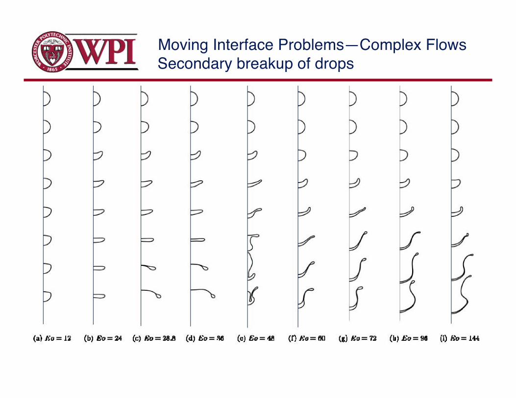
Moving Interface Problems—Complex FlowsSecondary breakup of drops

Moving Interface Problems—Complex FlowsSecondary breakup of drops
Moving Interface Problems—Complex Flows
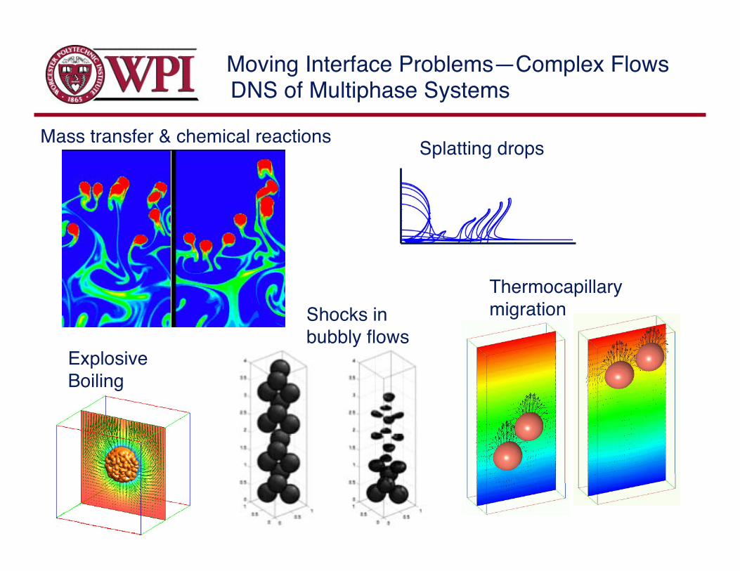
Splatting drops
Thermocapillarymigration
Mass transfer & chemical reactions
DNS of Multiphase Systems
ExplosiveBoiling
Shocks inbubbly flows

Moving Interface Problems—Complex Flows
Multifluid simulations of relatively simple systemsare well under control and can be used tounderstand such systems.
Large scale three-dimensional simulations areemerging. The challenge is to use the results toproduce engineering/scientific knowledge.
Methods for multiphase flows are in their infancy.
Summary
System size:<1980: Mostly two-dimensional systems1980: early three-dimensional studies1990: less than 1003 grid points2006 > 10003 grid points + new computational techniques