Embed Size (px)
Citation preview
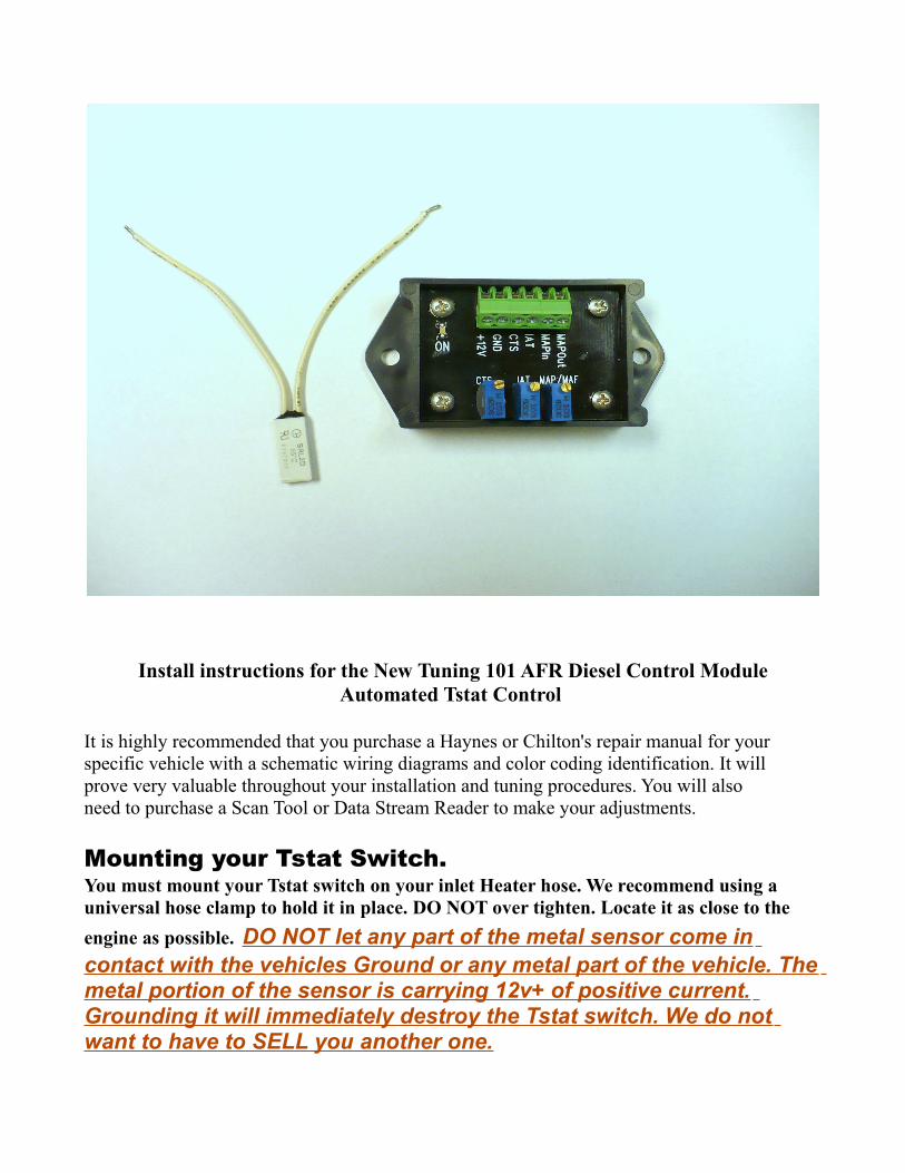
Install instructions for the New Tuning 101 AFR Diesel Control ModuleAutomated Tstat Control
It is highly recommended that you purchase a Haynes or Chilton's repair manual for yourspecific vehicle with a schematic wiring diagrams and color coding identification. It willprove very valuable throughout your installation and tuning procedures. You will alsoneed to purchase a Scan Tool or Data Stream Reader to make your adjustments.
Mounting your Tstat Switch.You must mount your Tstat switch on your inlet Heater hose. We recommend using a universal hose clamp to hold it in place. DO NOT over tighten. Locate it as close to the engine as possible. DO NOT let any part of the metal sensor come in contact with the vehicles Ground or any metal part of the vehicle. The metal portion of the sensor is carrying 12v+ of positive current. Grounding it will immediately destroy the Tstat switch. We do not want to have to SELL you another one.
Important Update for Tstat Switch Mounting
If you live in a cold winter climate, it is advise-able to wrapsome fiberglass pipe insulation around your hose and TstatSwitch, and then wrap your insulation, and Tstat Switch withblack electricians tape. This will insulate your Tstat Switch
from cold air flow when you are driving in Cooler temperatures.
The Tstat swich will automatically apply power ( turn on ) your Diesel AFR Control Module when the sensor on the Tstat Switch reaches 145 F. At this engine temperature, your
vehicles computer will accept the altered signals from your sensors without any problems or CEL's ( check engine lights )
All of the following adjustments should be made after the “On” LED on the module lights up.
Connecting Power to your Module
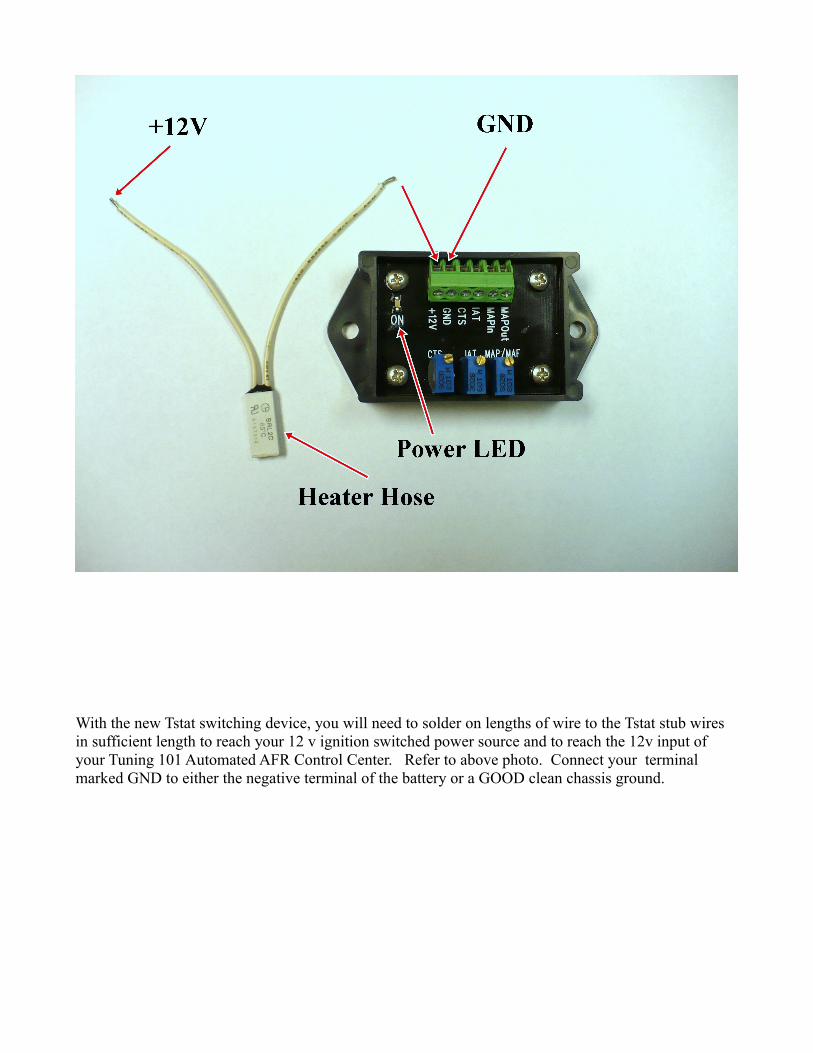
With the new Tstat switching device, you will need to solder on lengths of wire to the Tstat stub wires in sufficient length to reach your 12 v ignition switched power source and to reach the 12v input of your Tuning 101 Automated AFR Control Center. Refer to above photo. Connect your terminal marked GND to either the negative terminal of the battery or a GOOD clean chassis ground.

Connecting your MAF/MAP Enhancer
This AFR Diesel Control Center contains a voltage based MAF/MAP enhancer, which is prevalent in most vehicles today. There are some vehicles that use a frequency based MAF sensor and a voltage based MAP sensor. These are common, and are usually found in some Ford & GM products. If your vehicle has this combination, use which ever of the two sensors is voltage based. You do not need to adjust the signals of both. Either the MAF or the MAP will suffice. If your vehicle has a voltage based MAF sensor we recommend using the MAF.
Locate your MAF or MAP sensor. They will normally have three wires.
+ 5volt- GroundSignal Wire
Once again, cut the signal wire. Add additional wire if necessary to reach your EFIE mounting location.

The wire that goes directly to the MAF or MAP sensor is inserted into MAP In connector. The wire that goes to the computer is inserted into the MAP Out connector.
Finding the Signal Wire
Of course the easiest way to find the signal wire is to use your manual’s wiring diagram for your vehicle. This can tell you the exact wire, and it's color code, and save you some time. But if you didn’t take our advice and don't have a wiring diagram, you can still find your signal wire by measuring itA MAP or a MAF will have 3 wires. One will by 5 volts, which powers the device and is supplied by the ECU. One will be ground, or 0 volts. So if you measure the 3 wires, just eliminate the 5 volt wire and the 0 volt wire, and the remaining wire is the signal wire. This is slightly complicated by the fact that many MAF sensors today also include an Intake Air Temperature sensor in the same housing. In this case you'll have 5 wires going to the sensor. But it's OK, it's easy to find the correct wires you need. The temp sensor will have a ground wire and a signal wire. The signal wire will be up near 5 volts when the sensor is cold, but as it heats up that voltage gets lower. But a temp sensor's voltagewill not change when you goose the engine, and that's how you can tell the difference. Also, if you unplug the sensor, and measure the signal wire on the computer side, it will read 5 volts.
Now, how do you make sure your MAP is a voltage type, and not a frequency type? You will need to watch the voltage as you make changes to the engine's RPMs. The best way is to goose the engine. The voltage will change dramatically on either a MAP or a MAF if it is voltage type. You will see a small change in DC voltage for a frequency type device too, but the changes will be slight, like tenths of a volt. Whereas the changes on a voltage type will be much more dramatic. Changes of over a volt indicate a voltage type MAP or MAF.
Tip: You can steal a straight pin from your wife's sewing box and push it through the insulation of the wire you want to test. Make sure you get into the conductor (wire) inside. This will be much easier than scraping away the insulation to test the wire.Even if you find your signal wire using a diagram, you should still test it before proceeding. You must make sure that you see a voltage change when you rev the engine, and that the voltage drops back down when the engine slows back down again. If you see this phenomena, you can proceed to install the circuit. If you don't see this phenomena, then you have the wrong wire, or an incompatible sensor type. Do not try to use this circuit unless you find a signal wire that matches this phenomena. The biggest single cause of failure for any sensor modification project is to mis-identify the signal wire. Soit's best to be absolutely sure.
*Note If your vehicle is one of the very rare models that uses frequency based circuitry for both theMAF & MAP sensor this MAF/MAP enhancer will not work with your vehicle. Contact us and we willadvise you where you can purchase a frequency based MAF/MAP enhancer.

Connecting your IAT enhancer.
Locate your IAT ( intake air temperature ) sensor. There will be 2 wires going to the sensor. You will NOT be cutting any wires. You will skin off some of the insulation from the signal wire. Refer to your manuals diagram. Or you can refer to the document Identifying your signal wires. Solder on a length of wire sufficient in length to reach your AFR Control Center and attach it in the terminal marked IAT as pictured above.
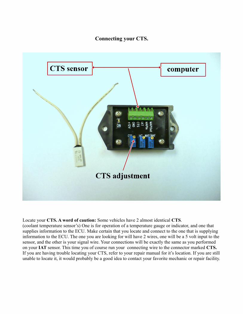
Connecting your CTS.
Locate your CTS. A word of caution: Some vehicles have 2 almost identical CTS. (coolant temperature sensor’s) One is for operation of a temperature gauge or indicator, and one that supplies information to the ECU. Make certain that you locate and connect to the one that is supplying information to the ECU. The one you are looking for will have 2 wires, one will be a 5 volt input to the sensor, and the other is your signal wire. Your connections will be exactly the same as you performed on your IAT sensor. This time you of course run your connecting wire to the connector marked CTS. If you are having trouble locating your CTS, refer to your repair manual for it’s location. If you are still unable to locate it, it would probably be a good idea to contact your favorite mechanic or repair facility.
Special AFR Control WarningCTS WIRING HOOKUP
There are a number of vehicles that use dual ( 2 ) CTS sensors. One of them is used to furnish the signal to the ECU, and the other is used to run a temperature gauge or a warning indicator light. It is EXTREMELY IMPORTANT that you attach to the correct CTS sensor. The sensor you will be attaching to will have a 5 volt input to the sensor. SOME, but not all of the manufacturers use a 12 volt input to the other sensor that powers your temperature gauge or indicator ( idiot ) light. If you accidentallyattach the 12 volt sensor to your AFR Control Center, you will destroy the unit.
Always check the voltage going to the sensor before connecting your wires to the CTS terminals on you AFR Control center. You can skin off a little insulation from one of the wires. Using your volt meter, attach your positive probe to the wire and your negative probe to ground. If your meter shows 5 volts or less you are safe and probably have the correct sensor. Although there are some model vehicles that use a 5 volt feed toboth of the CTS sensors. If this is the case you will need to refer to your repair manual to identify which sensor is which. We have already had one person that made this mistake and hooked to the wrong sensor and blew up his AFR Control Center.PLEASE DO NOT BE THE SECOND. We will repair it for you at a reasonable cost, but it will not be covered under warranty.
Pre-Setting your Control Potentiometers to their basic start positions.
After you have all of your connections made and all of your wiring is neatly and cleanly arranged, you will need to pre-set certain of your potentiometers. Turn your MAF/MAP, IAT, & CTS potentiometers full Counter clockwise.
Sequential Timing: What to expect.When you start your vehicle your ECU will take a barometric reading from you MAF/MAP sensor.When the temperature of your engine coolant in your radiator hose reaches 150 F. the power ON LED will light and activate the Diesel AFR add on.
Adjustment of your MAF/MAP Enhancer. With the engine running, and using your Scan Tool, turn the MAF/MAP potentiometer clockwise until you see a 10 to 15% reduction in air flow ( or Load ) on your Scan Tool.

Further fine tuning of this device will greatly improve your results. This can only be accomplished with a Scan Tool, or Live Data Stream reader.
Your objectives are to accomplish in the following order.
1. Use you MAF adjustment to lean out ( lessen ) the fuel supplied to and reduce your injector pulse rate.
2. Use your IAT adjustment to retard the ignition timing closer to TDC.3. Use you CTS adjustment to fool the computer and make it choose a leaner
mapping table.
MAF/MAP adjustment. You will want to adjust this adjustment to show a 10% to 15% load reduction on your scan tool or data stream reader.
CTS adjustment. You will want to adjust this adjustment to read a minimum of 10 degrees F. warmer than your engine's or radiator's thermostat rated temperature.
IAT adjustment. You will want to adjust this adjustment to read a minimum of 80 to 100 degrees F warmer than ambient temperature. ( normally in the 180 F. to 205 F. range )
These are all suggested starting position adjustments. You will need to make test runs and further fine tuning adjustments to attain maximum fuel savings. You very possibly will need to increase or decrease the amount of HHO from your HHO Generator to your engine to maximize your fuel gains.
There are a variety of Scan Tools and Live Data Stream programs that are transmitted to your lap top computer available on the market. Needless to say some are much more elaborate than others. Some are capable displaying your fuel reduction and injector pulse rate as well as your LTFT ( long term fuel trim ) and STFT ( short term fuel trim ). The more capabilities your device has, the easier the tuning process will be. Unlike the OBD II scan tools for gasoline powered vehicles which are using a universal diagnostic system, different scan devices, either vehicle or manufacturer specific, are required for most diesel's.
This device is designed to make adjustment's to 3 of the common sensors found in 95% of all diesel engines. These 3 sensors play a large roll in determining the vehicles AFR ( air fuel ratio ). In your diesel powered vehicle there may be other devices that also have an effect on AFR. This varies tremendously from one manufacturer to another, and from one model to another.

This device is designed to deal with the 3 major sensors found in common on most all diesel engines. It will NOT produce the amount of mileage gains that can be attained with the Tuning 101 AFR Control for gasoline powered engines, which is altering the signal from ALL of the sensors that effect AFR. This is due to the uniform and standard diagnostic system used by gasoline powered vehicles, and the lack of a uniform standard for diesel powered vehicles. When tuned properly the average mileage gain is in the 30% to 40% range. In our testing, we have had gains as high as 70% on some diesel vehicles, but also as low as 22% on one other. Overall condition of the vehicle, including its, sensors, filters, and ignition parts will play a big part of your success.