Embed Size (px)
Citation preview
Electric Actuators
Linear ActuatorType SAM -01 to SAM -52
Mounting andOperating Instructions
EB 8330 ENEdition April 1999
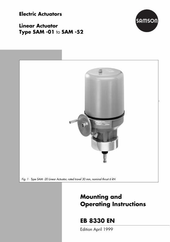
Fig. 1 ⋅ Type SAM -20 Linear Actuator, rated travel 30 mm, nominal thrust 6 kN

ContentsSafety instructions . . . . . . . . . . . . . . . . . . . . . . . . . . . . . . . . . . . . . . . . . . . . . . . 3
1 Principle of operation . . . . . . . . . . . . . . . . . . . . . . . . . . . . . . . . . . . . . . . . . . . . . 41.1 Application 51.2 Versions 51.3 Function 51.3.1 Electrical equipment 62 Technical data . . . . . . . . . . . . . . . . . . . . . . . . . . . . . . . . . . . . . . . . . . . . . . . . . . 8
3 Dimensions . . . . . . . . . . . . . . . . . . . . . . . . . . . . . . . . . . . . . . . . . . . . . . . . . . . 11
4 Installation . . . . . . . . . . . . . . . . . . . . . . . . . . . . . . . . . . . . . . . . . . . . . . . . . . . 124.1 Installation requirements 124.2 Mounting position 124.3 Attaching the actuator to a control valve 124.4 Manual operation 145 Electrical connection . . . . . . . . . . . . . . . . . . . . . . . . . . . . . . . . . . . . . . . . . . . . . 155.1 Removing the cover 165.2 Establishing the connection 175.3 Start-up 176 Connection examples . . . . . . . . . . . . . . . . . . . . . . . . . . . . . . . . . . . . . . . . . . . . 19
Connection example 1(three-way valve) 19Connection example 2 (globe valve) 20
7 Adjustment and calibration. . . . . . . . . . . . . . . . . . . . . . . . . . . . . . . . . . . . . . . . 217.1 Travel 217.2 Potentiometer 217.3 Electronic position transmitter 227.4 Limit switch WE-S3 247.5 Signal switch WE-S4 to WE-S6 248 Additional electrical equipment . . . . . . . . . . . . . . . . . . . . . . . . . . . . . . . . . . . . . 268.1 Heating 268.1.1 Retrofitting the heating resistor 269 Positioners. . . . . . . . . . . . . . . . . . . . . . . . . . . . . . . . . . . . . . . . . . . . . . . . . . . . 279.1 Electrical connection 279.1.1 Connecting the control line 289.1.2 Feedback signal 289.2 Corrections with potentiometer "A" and "B" 289.3 Reversing 299.4 Sequential mode 2910 Maintenance and service . . . . . . . . . . . . . . . . . . . . . . . . . . . . . . . . . . . . . . . . . 2910.1 Circuit diagram Type SAM - ... with positioner (maximum equipment) 30
Safety instructionsThe actuators described below are part of a power plant installation for industrial applications.They are designed in accordance with the generally applicable technical regulations.The connection and start-up of the linear actuators requires expert knowledge on the installationof power systems and equipment (according to DIN VDE 0100), on accident prevention regula-tions and the special start-up conditions for linear actuators.These measures require qualified personnel.According to these Mounting and Operating Instructions, qualified personnel is referred to asindividuals who are able to judge the work they are assigned to and recognize possible dangersdue to their specialized training, their knowledge and experience as well as their knowledge ofthe applicable standards, e. g.– training/instruction or authorization to activate/deactivate, isolate, ground, and mark de-
vices/systems according to the safety engineering standards, – training or instruction in accordance with the safety engineering standards regarding main-
tenance and application of suitable safety equipment,– first aid training.
Please observe the following special symbolsused in these Mounting and Operating In-structions.
Certain safety related information or instruc-tions are brought to your attention.
Electrical or live parts are unprotected andfreely accessible. Risk of death!
Symbols in these Mounting and Operating Instructions
•
!
!DANGER!Electrical power or live parts arefreely accessible. If instructions as per these Mountingand Operating Instructions are notfollowed, death or serious injury andproperty damage may result!
!
WARNING!Indicates a potentially hazardous situ-ation which, if not avoided, could re-sult in property damage or even per-sonal injury !
NOTE!Here, you will find supplementary details, in-formation and tips.
CAUTION!Indicates a potentially hazardous situ-ation which, if not avoided, maycause property damage!
1. Principle of operationThe Type SAM ... Electric Linear Actuators areequipped with reversible a.c. or three-phasea.c. motors. The rotary motion of the motor istransferred to the actuator stem via a gear unitand the corresponding transfer elementswhere it is converted into a linear "On-Off"motion.
In case the electrical power fails, you canoperate the actuator manually.
Special features– Nominal thrust from 2 to 25 kN– Rated travel 15, 30, 60 or 120 mm– Speed of response 13.5 to 50 mm/min– A.c. motor 230 V~, 50 Hz
or three-phase a.c. motor 400 V~, 50 Hz
– Degree of protection IP 65
DANGER!During installation and operation, suitable power supply systems must be usedto ensure that hazardous voltages are prevented from energizing the device instandard operating mode or in case of a faulty system or system parts.Otherwise, personal injury and/or property damage may result.Any hazards which could be caused by the process medium, the signal pressureand moving parts of the control valve are to be prevented by means of appropri-ate measure. The proper and safe operation of this device depends on the proper shippingand appropriate storage including attachments and installation as well as care-ful operation and maintenance.You are required to ensure the following:– Only qualified individuals must be assigned to work on this device.– These individuals are required to read and have understood the Mounting and
Operating Instructions supplied with this product as well as the product informa-tion.
– These Mounting and Operating Instructions must always be available. Makesure that the respective individuals strictly observe the instructions listed forany work to be performed.
– Where applicable, tools and measuring instruments must be used properlyand in accordance with their intended purpose. If required, use your own pro-tective gear.
– Work on this device or near this device must not be performed by unqualifiedpersonnel.
!
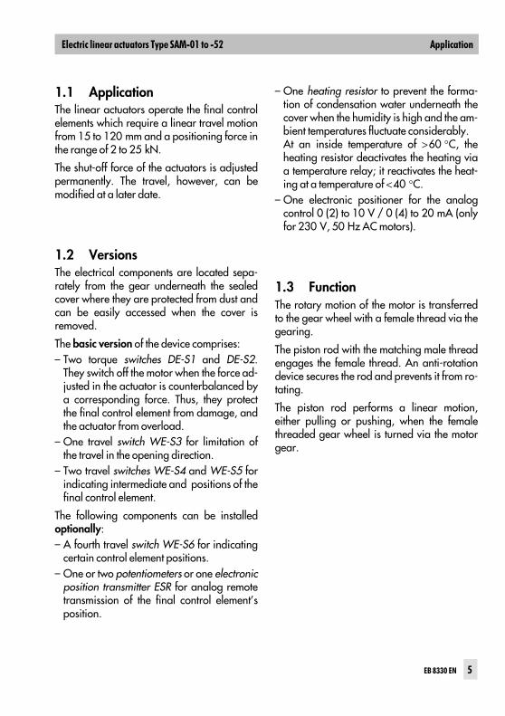
1.1 ApplicationThe linear actuators operate the final controlelements which require a linear travel motionfrom 15 to 120 mm and a positioning force inthe range of 2 to 25 kN.
The shut-off force of the actuators is adjustedpermanently. The travel, however, can bemodified at a later date.
1.2 VersionsThe electrical components are located sepa-rately from the gear underneath the sealedcover where they are protected from dust andcan be easily accessed when the cover isremoved.
The basic version of the device comprises:– Two torque switches DE-S1 and DE-S2.
They switch off the motor when the force ad-justed in the actuator is counterbalanced bya corresponding force. Thus, they protectthe final control element from damage, andthe actuator from overload.
– One travel switch WE-S3 for limitation ofthe travel in the opening direction.
– Two travel switches WE-S4 and WE-S5 forindicating intermediate and positions of thefinal control element.
The following components can be installedoptionally:– A fourth travel switch WE-S6 for indicating
certain control element positions.– One or two potentiometers or one electronic
position transmitter ESR for analog remotetransmission of the final control element’sposition.
– One heating resistor to prevent the forma-tion of condensation water underneath thecover when the humidity is high and the am-bient temperatures fluctuate considerably.At an inside temperature of >60 °C, theheating resistor deactivates the heating viaa temperature relay; it reactivates the heat-ing at a temperature of <40 °C.
– One electronic positioner for the analogcontrol 0 (2) to 10 V / 0 (4) to 20 mA (onlyfor 230 V, 50 Hz AC motors).
1.3 FunctionThe rotary motion of the motor is transferredto the gear wheel with a female thread via thegearing.
The piston rod with the matching male threadengages the female thread. An anti-rotationdevice secures the rod and prevents it from ro-tating.
The piston rod performs a linear motion,either pulling or pushing, when the femalethreaded gear wheel is turned via the motorgear.
1.3.1 Electrical equipmentThe electrical equipment is located under-neath the removable housing cover.
In addition to the torque switches DE-S1 andDE-S2 as well as three travel switches WE-S3,S4 and S5, the actuator can be equipped withthe following switching elements and measur-ing instruments:– One travel switch WE-S6– Two potentiometers POT R1 and POT R2– One electronic position transmitter ESR– One positioner
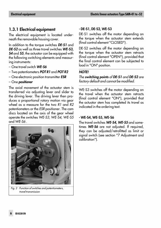
The axial movement of the actuator stem istransferred via adjusting lever and slider tothe driving lever. The driving lever then pro-duces a proportional rotary motion via gearwheel as a measure for the two R1 and R2potentiometers or the ESR positioner. The camdiscs located on the axis of the gear wheeloperate the switches WE-S3, WE-S4, WE-S5and WE-S6 .
- DE-S1, DE-S2, WE-S3 DE-S1 switches off the motor depending onthe torque when the actuator stem extends(final control element "CLOSED") .
DE-S2 switches off the motor depending onthe torque when the actuator stem retracts(final control element "OPEN"), provided thatthe final control element can be subjected toload in "ON" position.
WE-S3 switches off the motor depending onthe travel when the actuator stem retracts(final control element "ON"), provided thatthe actuator stem has completed its travel asindicated in the ordering text.
- WE-S4, WE-S5, WE-S6The travel switches WE-S4, WE-S5 and some-times WE-S6 are not adjusted. If required,they can be adjusted/retrofitted as limit orsignal switch (see section "7 Adjustment andcalibration").
Fig. 2 ⋅ Function of switches and potentiometers, travel transmission
NOTE!The switching points of DE-S1 and DE-S2 arefactory default and cannot be modified.
!
"#
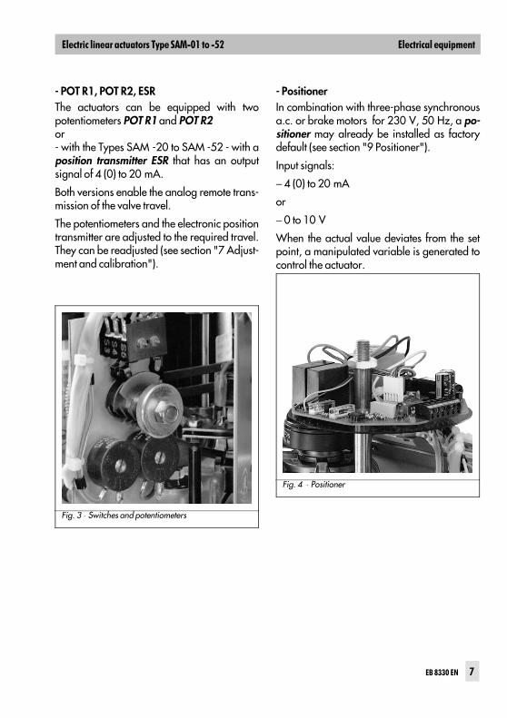
- POT R1, POT R2, ESRThe actuators can be equipped with twopotentiometers POT R1 and POT R2or - with the Types SAM -20 to SAM -52 - with aposition transmitter ESR that has an outputsignal of 4 (0) to 20 mA.
Both versions enable the analog remote trans-mission of the valve travel.
The potentiometers and the electronic positiontransmitter are adjusted to the required travel.They can be readjusted (see section "7 Adjust-ment and calibration").
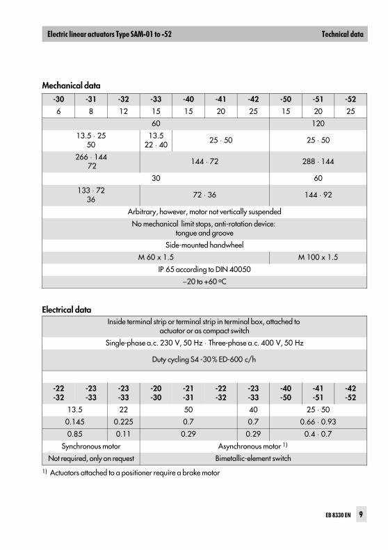
- PositionerIn combination with three-phase synchronousa.c. or brake motors for 230 V, 50 Hz, a po-sitioner may already be installed as factorydefault (see section "9 Positioner").
Input signals:
− 4 (0) to 20 mA
or
− 0 to 10 V
When the actual value deviates from the setpoint, a manipulated variable is generated tocontrol the actuator.
Fig. 3 ⋅ Switches and potentiometers
Fig. 4 ⋅ Positioner
$
"#

2 Technical dataTable 1 ⋅ Mechanical data
Type SAM ... -01 -10 -11 -12 -13 -20 -21 -22 -23
Nominal thrust kN 2 2 3.5 4.5 6 6 8 12 15
Rated travel mm 30
Speed ofresponse mm/min 15 17 ⋅ 25 ⋅ 50 17
34 13.5 ⋅ 25 ⋅ 50 13.522 ⋅ 40
Transit time at rated travel s 120 106 ⋅ 72 ⋅ 36 10653 133 ⋅ 72 ⋅ 36 133
82 ⋅ 45
Adjusted travel mm 15
Transit time s 60 53 ⋅ 36 ⋅ 18 5326 67 ⋅ 36 ⋅ 18 67 ⋅ 40
22.5
Mounting position Arbitrary, however, motor not vertically suspended.
Actuator stem No mechanical limit stops, anti-rotation device: tongue and groove
Handwheel Side-mounted handwheel
Connecting thread M 30 x 1.5
Degree of protection IP 65 according to DIN 40050
Perm. ambient temperature −20 to +60 oC
Table 2 ⋅ Electrical data
Electrical connection Inside terminal strip or terminal strip in terminal box, attached toactuator or as compact switch
Connected load Single-phase a.c. 230 V, 50 Hz ⋅ Three-phase a.c. 400 V, 50 Hz
Operating mode acc. to VDE 0530 Part 1, section 4 Duty cycling S4 -30% ED-600 c/h
Power consumption
Type SAM ... Actuator -01 -10 -11 -12 -13 -20-30
-21-31
Speed of response [mm/min.] 15 17 ⋅ 25 50 17 ⋅ 34 13.5 ⋅ 25
Nominalcurrent [A]
Motor 230 V~/50 Hz 0.029 0.16 0.18 0.16 ⋅ 0.18 0.1 ⋅ 0.225
Motor 400 V~/50 Hz 0.015 0.11 0.08 0.11 ⋅ 0.08 0.062 ⋅ 0.11
Motor type Synchronous motor
Temperature monitor Not required, only on request
%&
Mechanical data
-30 -31 -32 -33 -40 -41 -42 -50 -51 -52
6 8 12 15 15 20 25 15 20 25
60 120
13.5 ⋅ 2550
13.522 ⋅ 40 25 ⋅ 50 25 ⋅ 50
266 ⋅ 144 72 144 ⋅ 72 288 ⋅ 144
30 60
133 ⋅ 7236 72 ⋅ 36 144 ⋅ 92
Arbitrary, however, motor not vertically suspended
No mechanical limit stops, anti-rotation device: tongue and groove
Side-mounted handwheel
M 60 x 1.5 M 100 x 1.5
IP 65 according to DIN 40050
−20 to +60 oC
Electrical dataInside terminal strip or terminal strip in terminal box, attached to
actuator or as compact switch
Single-phase a.c. 230 V, 50 Hz ⋅ Three-phase a.c. 400 V, 50 Hz
-22-32
-23-33
-23-33
-20-30
-21-31
-22-32
-23-33
-40-50
-41-51
-42-52
13.5 22 50 40 25 ⋅ 50
0.145 0.225 0.7 0.7 0.66 ⋅ 0.93
0.85 0.11 0.29 0.29 0.4 ⋅ 0.7
Synchronous motor Asynchronous motor 1)
Not required, only on request Bimetallic-element switch
1) Actuators attached to a positioner require a brake motor
Duty cycling S4 -30% ED-600 c/h
'
%&
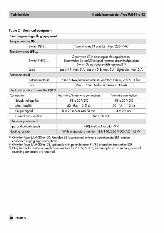
Table 2 ⋅ Electrical equipment
Switching and signalling equipment
Torque switches DE- ...
Switch DE-S ... Two switches S1 and S2 ⋅ Max. 250 V AC
Travel switches WE-...
Switch WE-S ...One switch S3 in opening or closing direction
Two switches S4 and S5 to signal intermediate or final positionsSwitch S6 as signal switch (optional) 1)
Load cos ϕ = 1: max. 5 A ⋅ cos ϕ = 0.8: max. 3 A ⋅ Lightbulbs: max. 2 A
Potentiometer R
Potentiometer R ... One or two potentiometers R1 and R2 : 110 Ω, 200 Ω, 1 kΩ
Load Max. 1.5 W ⋅ Slider current max. 30 mA
Electronic position transmitter ESR 2)
Connection Four-wire/three-wire connection Two-wire connection
Supply voltage UH 18 to 30 V DC 18 to 30 V DC
Max. load RL 50 ⋅ (UH − 2.5) Ω 50 ⋅ (UH − 12) Ω
Output signal 0 to 20 mA or 4 to 20 mA 4 to 20 mA
Current consumption Max. 30 mA
Electronic positioner 3)
Input and output signals 4 (0) to 20 mA or 0 to 10 V
Heating resistor With temperature monitor ⋅ 24/110/230 V DC/AC ⋅ 15 W
1) Only for Type SAM-20 to -50: Provided S6 is connected, only one potentiometer (R1) can be connected in plug-type connections.
2) Only for Type SAM-20 to -52, optionally with potentiometer R1/R2 or position transmitter ESR3) Only for brake motors or synchronous motors for 230 V, 50 Hz; for three-phase a.c. motors, external
reversing contactors are required.
%&
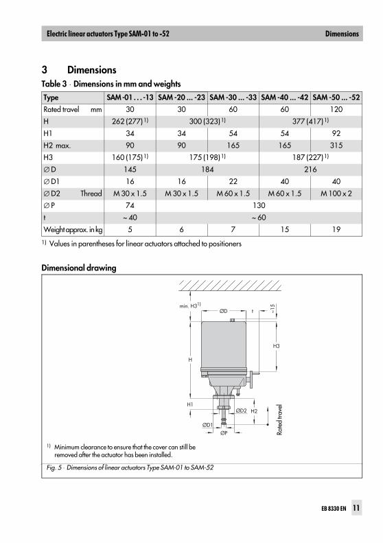
3 Dimensions
Dimensional drawing
Table 3 ⋅ Dimensions in mm and weights
Type SAM -01 . . . -13 SAM -20 ... -23 SAM -30 ... -33 SAM -40 ... -42 SAM -50 ... -52
Rated travel mm 30 30 60 60 120
H 262 (277)1) 300 (323)1) 377 (417)1)
H1 34 34 54 54 92
H2 max. 90 90 165 165 315
H3 160 (175)1) 175 (198)1) 187 (227)1)
∅ D 145 184 216
∅ D1 16 16 22 40 40
∅ D2 Thread M 30 x 1.5 M 30 x 1.5 M 60 x 1.5 M 60 x 1.5 M 100 x 2
∅ P 74 130
t ~ 40 ~ 60
Weight approx. in kg 5 6 7 15 19
1) Values in parentheses for linear actuators attached to positioners
ØD t
H3
~15
H2H1
ØPØD1
ØD2
H
min. H31)
Rate
d tra
vel
1) Minimum clearance to ensure that the cover can still beremoved after the actuator has been installed.
Fig. 5 ⋅ Dimensions of linear actuators Type SAM-01 to SAM-52
(#
4 Installation4.1 Installation requirementsPrior to installation, make sure that the follow-ing requirements are met: – Proper voltages and control signals re-
quired to operate the actuator are avail-able.
– Electrical lines are de-energized.– Pipelines are depressurized and cold.
Choose the attachment position of the linearactuator so as to ensure the following: – The actuator can be easily accessed.– There is sufficient space to remove the cover
(see "3 Dimensions").– The actuator is protected against excessive
heat radiation.– The ambient temperature is in the range
from -20 to +60 °C.
If installed outdoors, the actuator must be pro-tected with an additional cover, e.g. againsthumidity (rain, snow), heat (direct sunlight),cold (frost), excessive draft, dust, etc.
When ambient temperatures are subjected tostrong fluctuations and if the humidity is high,we recommend installing a heating resistor tominimize the formation of condensate in thehousing (see "8.1 Heating").
If installed in an environment with a high pol-lutant concentration, (e.g. in areas with a hightraffic volume, industrial areas, near coastalregions), the external actuator parts must bemade of non-corrosive material and becoated with a special finish.
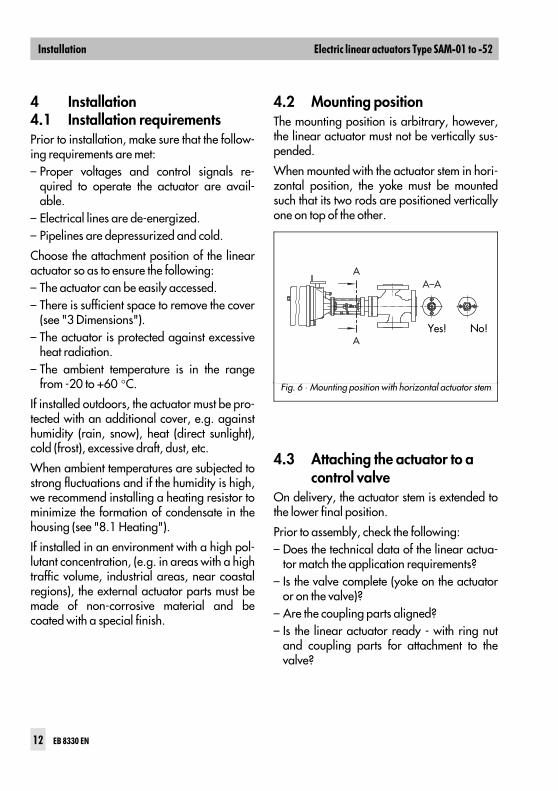
4.2 Mounting positionThe mounting position is arbitrary, however,the linear actuator must not be vertically sus-pended.
When mounted with the actuator stem in hori-zontal position, the yoke must be mountedsuch that its two rods are positioned verticallyone on top of the other.
4.3 Attaching the actuator to a control valve
On delivery, the actuator stem is extended tothe lower final position.
Prior to assembly, check the following:– Does the technical data of the linear actua-
tor match the application requirements?– Is the valve complete (yoke on the actuator
or on the valve)?– Are the coupling parts aligned?– Is the linear actuator ready - with ring nut
and coupling parts for attachment to thevalve?
AA–A
AYes! No!
Fig. 6 ⋅ Mounting position with horizontal actuator stem
)
– If required, are additional accessories al-ready installed in the actuator?
– Does the operating voltage to be connectedmatch that of the actuator?
– Does the data on the name plate match themotor data?
– Does the adjusted travel of the actuator orthe travel to be adjusted also match thevalve travel?
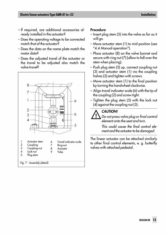
Procedure– Insert plug stem (5) into the valve as far as it
will go.– Move actuator stem (1) to mid-position (see
"4.4 Manual operation").– Place actuator (8) on the valve bonnet and
secure with ring nut (7) (allow to fall over thestem when placing).
– Push plug stem (5) up, connect coupling nut(3) and actuator stem (1) via the couplinghalves (2) and tighten with screws.
– Move actuator stem (1) to the final positionby turning the handwheel clockwise.
– Align travel indicator scale (6) with the tip ofthe coupling (2) and screw tight.
– Tighten the plug stem (5) with the lock nut(4) against the coupling nut (3).
The linear actuator can be attached similarlyto other final control elements, e. g. butterflyvalves with attached pedestal.
!
8
7
1
234
5
9
6
1 Actuator stem2 Coupling3 Coupling nut4 Lock nut5 Plug stem
6 Travel indicator scale7 Ring nut8 Actuator9 Yoke
Fig. 7 ⋅ Assembly (detail)
CAUTION!Do not press valve plug or final controlelement onto the seat and turn. This could cause the final control ele-ment and the actuator to be damaged.
)
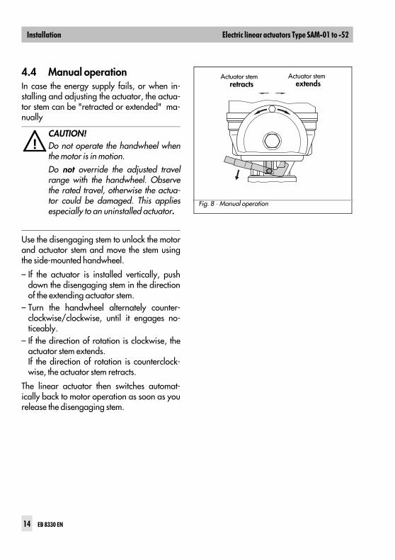
4.4 Manual operationIn case the energy supply fails, or when in-stalling and adjusting the actuator, the actua-tor stem can be "retracted or extended" ma-nually
Use the disengaging stem to unlock the motorand actuator stem and move the stem usingthe side-mounted handwheel.
– If the actuator is installed vertically, pushdown the disengaging stem in the directionof the extending actuator stem.
– Turn the handwheel alternately counter-clockwise/clockwise, until it engages no-ticeably.
– If the direction of rotation is clockwise, theactuator stem extends.If the direction of rotation is counterclock-wise, the actuator stem retracts.
The linear actuator then switches automat-ically back to motor operation as soon as yourelease the disengaging stem.
!
Actuator stem extends
Actuator stem retracts
Fig. 8 ⋅ Manual operation
CAUTION!Do not operate the handwheel whenthe motor is in motion.Do not override the adjusted travelrange with the handwheel. Observethe rated travel, otherwise the actua-tor could be damaged. This appliesespecially to an uninstalled actuator.
)
5 Electrical connection
!DANGER!The connection and start-up of the linear actuators requires expert knowledgeon the installation of power systems and equipment (according to DIN VDE0100), on accident prevention regulations and the special start-up conditions forlinear actuators.This type of work must be performed by qualified personnel only (see p. 3"Safety instructions").– Be sure to disconnect the voltage prior to connecting the actuator to the power
supply. Ensure that the voltage cannot be switched on again accidentally!– When installing the local lines and establishing the connection, you are re-
quired to observe the DIN-/VDE regulations as well as the regulations of yourlocal energy supplier.
– Be sure to check that the mains supply voltage and the system frequencymatch the data on the name plate of the linear actuator as well as the actua-tor’s name plate.
– The cross section of line must be sized in accordance with the respectivepower consumption of the linear actuator and the required line length. Minimum cross section of lines: 1.5 mm2 or according to the local regulations.Cross sections of lines that are not large enough are often the cause of sup-posed "malfunctions".
– Fuse of the system: max. 6 A– Upstream controllers or switching devices must be sized sufficiently. If re-
quired, install a coupling relay between them.– Isolation of the system’s power supply; to isolate and disconnect the power
supply line from the actuator for maintenance and calibration purposes, theproper stop controls must be used which guarantee an all-pole disconnection(except earth) when switched off. These stop controls must be lockable whenswitched off and guarded against being switched on unintentionally.
– Use appropriate power supply systems which ensure that no hazardous volt-ages may reach the device in standard operation or in case of fault.
If you do not observe these safety regulations, death, severe physical injury orconsiderable property damage may occur.
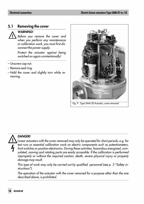
5.1 Removing the cover
– Unscrew cap nut.– Remove seal ring.– Hold the cover and slightly turn while re-
moving.
!
!
DANGER!Linear actuators with the cover removed may only be operated for short periods, e.g. fortest runs or essential calibration work on electric components such as potentiometers,limit switches or position electronics. During these activities, hazardous energized, unin-sulated, moving and rotating parts are easily accessible. If the calibration is performedimproperly or without the required caution, death, severe physical injury or propertydamage may result.This type of work may only be carried out by qualified personnel (see p. 3 "Safety in-structions").The operation of the actuator with the cover removed for a purpose other than the onedescribed above, is prohibited.
Fig. 9 ⋅ Type SAM-20 Actuator, cover removed
WARNING!Before you remove the cover andwhen you perform any maintenanceor calibration work, you must first dis-connect the power supply.Protect the actuator against beingswitched on again unintentionally!
!
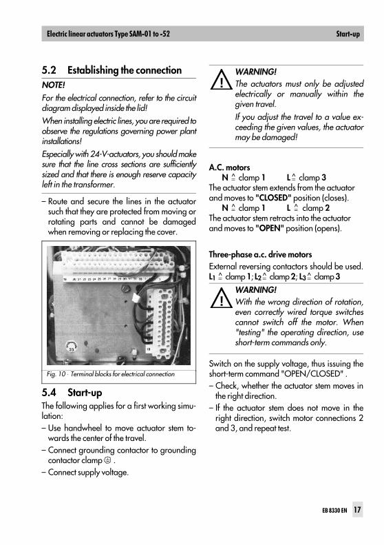
5.2 Establishing the connection
– Route and secure the lines in the actuatorsuch that they are protected from moving orrotating parts and cannot be damagedwhen removing or replacing the cover.
5.4 Start-upThe following applies for a first working simu-lation:– Use handwheel to move actuator stem to-
wards the center of the travel.– Connect grounding contactor to grounding
contactor clamp .– Connect supply voltage.
A.C. motorsN = clamp 1 L = clamp 3
The actuator stem extends from the actuatorand moves to "CLOSED" position (closes).
N = clamp 1 L = clamp 2The actuator stem retracts into the actuatorand moves to "OPEN" position (opens).
Three-phase a.c. drive motorsExternal reversing contactors should be used.L1 = clamp 1; L2 = clamp 2; L3 = clamp 3
Switch on the supply voltage, thus issuing theshort-term command "OPEN/CLOSED" .– Check, whether the actuator stem moves in
the right direction.– If the actuator stem does not move in the
right direction, switch motor connections 2and 3, and repeat test.
!
!
WARNING!The actuators must only be adjustedelectrically or manually within thegiven travel.If you adjust the travel to a value ex-ceeding the given values, the actuatormay be damaged!
NOTE!For the electrical connection, refer to the circuitdiagram displayed inside the lid! When installing electric lines, you are required toobserve the regulations governing power plantinstallations!Especially with 24-V-actuators, you should makesure that the line cross sections are sufficientlysized and that there is enough reserve capacityleft in the transformer.
Fig. 10 ⋅ Terminal blocks for electrical connection
WARNING!With the wrong direction of rotation,even correctly wired torque switchescannot switch off the motor. When"testing" the operating direction, useshort-term commands only.
$
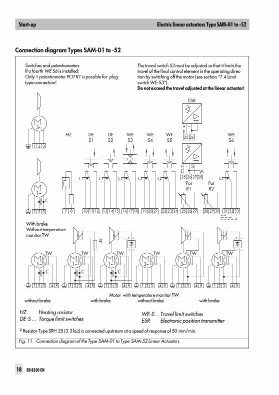
Connection diagram Types SAM-01 to -52
WE-S ...Travel limit switchesESR Electronic position transmitter
1
1~ 1~
TWTW
C C C
TW TW TW TW
1~ 3~ 3~ 3~
2 3 4 5 1 2 3
10 11 127 8 16 17 1813 14 15 19 20 21 25 26 27
25
ESR
WES6
HZ DES1
DES2
WES3
WES4
WES5
PotR1
+E
_ SA
PotR2
26
25
+E
_
26
27 28
28 29 30 31 32 3322 23 24
4
~ ~
+ _
~ ~
+ _
5 1 2 3 4 5 1 2 3 4 5 1 2 3 4 5 1 2 3 4 5
1~
C
1 2 3
3~
1 2 3
2)
Switches and potentiometersIf a fourth WE S6 is installed:Only 1 potentiometer POT R1 is possible for plug-type connection!
The travel switch S3 must be adjusted so that it limits thetravel of the final control element in the operating direc-tion by switching off the motor (see section "7.4 Limitswitch WE-S3").Do not exceed the travel adjusted at the linear actuator!
Motor with temperature monitor TWwithout brake with brake without brake with brake
2) Resistor Type SRH 25 (3.3 kΩ) is connected upstream at a speed of response of 50 mm/min.
HZ Heating resistorDE-S ... Torque limit switches
With brakeWithout temperaturemonitor TW
Fig. 11 ⋅ Connection diagram of the Type SAM-01 to Type SAM-52 Linear Actuators
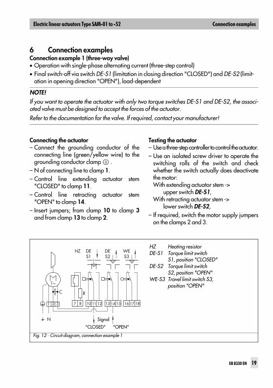
6 Connection examplesConnection example 1 (three-way valve)• Operation with single-phase alternating current (three-step control)• Final switch-off via switch DE-S1 (limitation in closing direction "CLOSED") and DE-S2 (limit-
ation in opening direction "OPEN"), load-dependent
Connecting the actuator– Connect the grounding conductor of the
connecting line (green/yellow wire) to thegrounding conductor clamp .
– N of connecting line to clamp 1.– Control line extending actuator stem
"CLOSED" to clamp 11.– Control line retracting actuator stem
"OPEN" to clamp 14.– Insert jumpers; from clamp 10 to clamp 3
and from clamp 13 to clamp 2.
Testing the actuator– Use a three-step controller to control the actuator.– Use an isolated screw driver to operate the
switching rolls of the switch and checkwhether the switch actually does deactivatethe motor:With extending actuator stem -> upper switch DE-S1,With retracting actuator stem -> lower switch DE-S2,
– If required, switch the motor supply jumperson the clamps 2 and 3.
N
7 81 2 3 13 14 1510 11 12 16 17 18
HZ
1~
C R
DES1
DES2
WES3
HZ Heating resistorDE-S1 Torque limit switch
S1, position "CLOSED"DE-S2 Torque limit switch
S2, position "OPEN"WE-S3 Travel limit switch S3,
position "OPEN"
Signal
"CLOSED" "OPEN"
Fig. 12 ⋅ Circuit diagram, connection example 1
NOTE!If you want to operate the actuator with only two torque switches DE-S1 and DE-S2, the associ-ated valve must be designed to accept the forces of the actuator. Refer to the documentation for the valve. If required, contact your manufacturer!
'
*#
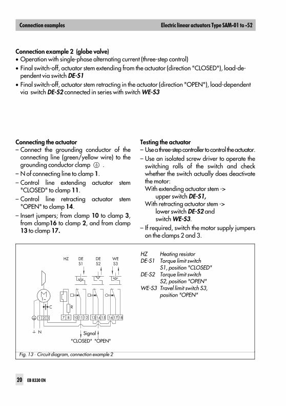
Connection example 2 (globe valve)• Operation with single-phase alternating current (three-step control) • Final switch-off, actuator stem extending from the actuator (direction "CLOSED"), load-de-
pendent via switch DE-S1• Final switch-off, actuator stem retracting in the actuator (direction "OPEN"), load-dependent
via switch DE-S2 connected in series with switch WE-S3
Connecting the actuator– Connect the grounding conductor of the
connecting line (green/yellow wire) to thegrounding conductor clamp .
– N of connecting line to clamp 1.– Control line extending actuator stem
"CLOSED" to clamp 11.– Control line retracting actuator stem
"OPEN" to clamp 14.– Insert jumpers; from clamp 10 to clamp 3,
from clamp16 to clamp 2, and from clamp13 to clamp 17.
Testing the actuator– Use a three-step controller to control the actuator.– Use an isolated screw driver to operate the
switching rolls of the switch and checkwhether the switch actually does deactivatethe motor:With extending actuator stem -> upper switch DE-S1,With retracting actuator stem -> lower switch DE-S2 and switch WE-S3.
– If required, switch the motor supply jumperson the clamps 2 and 3.
N
7 81 2 3 13 14 1510 11 12 16 17 18
HZ
1~
C R
DES1
DES2
WES3
HZ Heating resistorDE-S1 Torque limit switch
S1, position "CLOSED"DE-S2 Torque limit switch
S2, position "OPEN"WE-S3 Travel limit switch S3,
position "OPEN"
Signal
"CLOSED" "OPEN"
Fig. 13 ⋅ Circuit diagram, connection example 2
*#
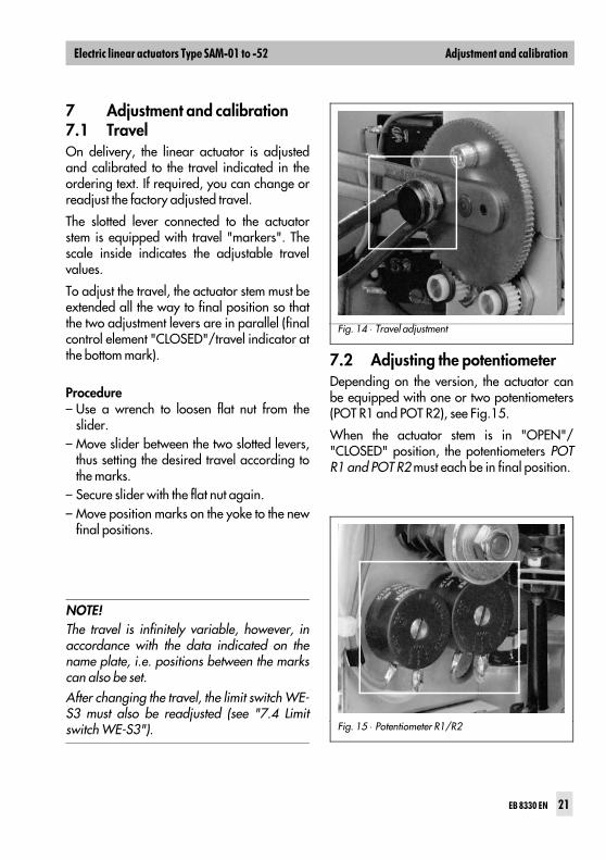
7 Adjustment and calibration7.1 TravelOn delivery, the linear actuator is adjustedand calibrated to the travel indicated in theordering text. If required, you can change orreadjust the factory adjusted travel.
The slotted lever connected to the actuatorstem is equipped with travel "markers". Thescale inside indicates the adjustable travelvalues.
To adjust the travel, the actuator stem must beextended all the way to final position so thatthe two adjustment levers are in parallel (finalcontrol element "CLOSED"/travel indicator atthe bottom mark).
Procedure– Use a wrench to loosen flat nut from the
slider.– Move slider between the two slotted levers,
thus setting the desired travel according tothe marks.
– Secure slider with the flat nut again.– Move position marks on the yoke to the new
final positions.
7.2 Adjusting the potentiometerDepending on the version, the actuator canbe equipped with one or two potentiometers(POT R1 and POT R2), see Fig.15.
When the actuator stem is in "OPEN"/"CLOSED" position, the potentiometers POTR1 and POT R2 must each be in final position.
Fig. 14 ⋅ Travel adjustment
NOTE!The travel is infinitely variable, however, inaccordance with the data indicated on thename plate, i.e. positions between the markscan also be set.After changing the travel, the limit switch WE-S3 must also be readjusted (see "7.4 Limitswitch WE-S3"). Fig. 15 ⋅ Potentiometer R1/R2
&+# &,
You can readjust the two potentiometers:– Use handwheel to move the linear actuator
to the final position "actuator stem ex-tended" ("CLOSED") until DE-S1 switches.Adjusting lever and driving lever must be inparallel in their tilted position.
– Use an appropriate screwdriver to move theslider of the potentiometers to final position.For this, turn the potentiometer shaftcounterclockwise until the stop can be justfelt.
– Move actuator by the adjusted travel to thefinal position "actuator stem retracted"("OPEN"). The potentiometers are then ro-tated into the other final position.
– Use a measuring instrument (ohmmeter) tomonitor the potentiometer movement andcheck whether the entire potentiometerrange is being covered.
For actuators with installed electric positioner,R1 is internally linked to the controller. Its re-sistance value is therefore not transmitted tothe outside for indication.
7.3 Electr. position transmitterType SAM-20 to -52 Linear Actuators can beequipped with an electronic position transmit-ter ESR in place of the two R1/R2 poten-tiometers.
The transmitter’s output signal indicates viaoutput current in the range from 4 (0) to20 mA the position of the final control ele-ment. Therefore, it is especially suited forremote transmission of the position.
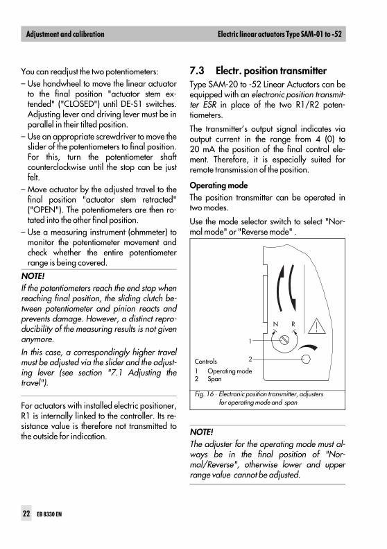
Operating modeThe position transmitter can be operated intwo modes.
Use the mode selector switch to select "Nor-mal mode" or "Reverse mode" .
NOTE!The adjuster for the operating mode must al-ways be in the final position of "Nor-mal/Reverse", otherwise lower and upperrange value cannot be adjusted.
NOTE!If the potentiometers reach the end stop whenreaching final position, the sliding clutch be-tween potentiometer and pinion reacts andprevents damage. However, a distinct repro-ducibility of the measuring results is not givenanymore.In this case, a correspondingly higher travelmust be adjusted via the slider and the adjust-ing lever (see section "7.1 Adjusting thetravel").
1
N R
2Controls1 Operating mode2 Span
Fig. 16 ⋅ Electronic position transmitter, adjusters for operating mode and span
&+# &,
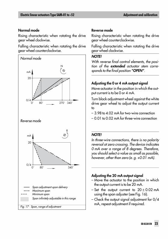
Normal modeRising characteristic when rotating the drivegear wheel clockwise.
Falling characteristic when rotating the drivegear wheel counterclockwise.
Reverse modeRising characteristic when rotating the drivegear wheel counterclockwise.
Falling characteristic when rotating the drivegear wheel clockwise.
Adjusting the 0 or 4 mA output signal Move actuator in the position in which the out-put current is to be 0 or 4 mA.
Turn black adjustment wheel against the whitedrive gear wheel to adjust the output currentto– 3.98 to 4.02 mA for two-wire connection– 0.01 to 0.02 mA for three-wire connection
Adjusting the 20 mA output signal– Move the actuator to the position in which
the output current is to be 20 mA.– Set the output current to 20 ± 0.02 mA
using the span adjuster (see Fig. 16).– Check the output signal adjustment for 0/4
mA, repeat adjustment if required.
Reverse mode
Span adjustment upon deliveryMaximum spanMinimum spanSpan infinitely adjustable in this range
mA
0˚
N
0/4
20
80˚ 270˚ 340˚
0˚0/4
20
mA
80˚ 340˚
R
Normal mode
Fig. 17 ⋅ Span, range of adjustment
NOTE!With reverse final control elements, the posi-tion of the extended actuator stem corre-sponds to the final position "OPEN".
NOTE!In three-wire connections, there is no polarityreversal at zero crossing. The device indicates0 mA over a range of 8 degrees. Therefore,you should select a value as small as possible,however, other than zero (e. g. +0.01 mA).
&+# &,
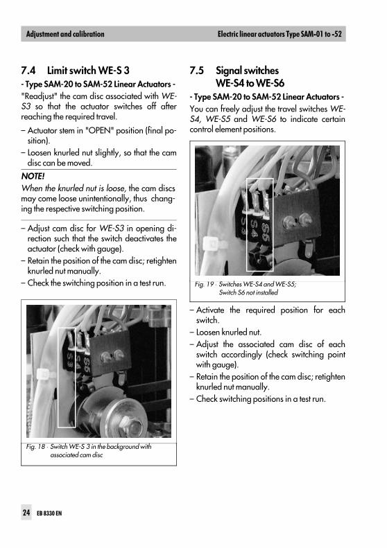
7.4 Limit switch WE-S 3 - Type SAM-20 to SAM-52 Linear Actuators -"Readjust" the cam disc associated with WE-S3 so that the actuator switches off afterreaching the required travel.
– Actuator stem in "OPEN" position (final po-sition).
– Loosen knurled nut slightly, so that the camdisc can be moved.
– Adjust cam disc for WE-S3 in opening di-rection such that the switch deactivates theactuator (check with gauge).
– Retain the position of the cam disc; retightenknurled nut manually.
– Check the switching position in a test run.
7.5 Signal switches WE-S4 to WE-S6
- Type SAM-20 to SAM-52 Linear Actuators -You can freely adjust the travel switches WE-S4, WE-S5 and WE-S6 to indicate certaincontrol element positions.
– Activate the required position for eachswitch.
– Loosen knurled nut.– Adjust the associated cam disc of each
switch accordingly (check switching pointwith gauge).
– Retain the position of the cam disc; retightenknurled nut manually.
– Check switching positions in a test run.
NOTE!When the knurled nut is loose, the cam discsmay come loose unintentionally, thus chang-ing the respective switching position.
Fig. 18 ⋅ Switch WE-S 3 in the background with associated cam disc
Fig. 19 ⋅ Switches WE-S4 and WE-S5; Switch S6 not installed
&+# &,
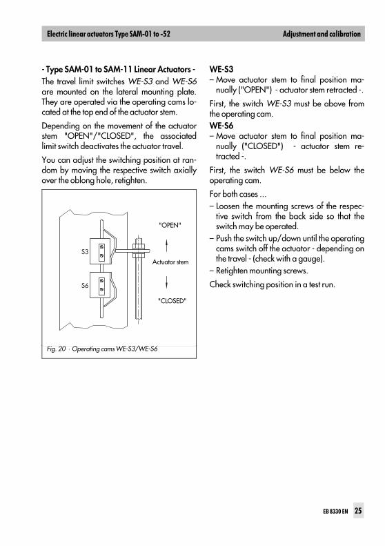
- Type SAM-01 to SAM-11 Linear Actuators -The travel limit switches WE-S3 and WE-S6are mounted on the lateral mounting plate.They are operated via the operating cams lo-cated at the top end of the actuator stem.
Depending on the movement of the actuatorstem "OPEN"/"CLOSED", the associatedlimit switch deactivates the actuator travel.
You can adjust the switching position at ran-dom by moving the respective switch axiallyover the oblong hole, retighten.
WE-S3– Move actuator stem to final position ma-
nually ("OPEN") - actuator stem retracted -.
First, the switch WE-S3 must be above fromthe operating cam.WE-S6– Move actuator stem to final position ma-
nually ("CLOSED") - actuator stem re-tracted -.
First, the switch WE-S6 must be below theoperating cam.
For both cases ...– Loosen the mounting screws of the respec-
tive switch from the back side so that theswitch may be operated.
– Push the switch up/down until the operatingcams switch off the actuator - depending onthe travel - (check with a gauge).
– Retighten mounting screws.
Check switching position in a test run.
S3
S6
"OPEN"
Actuator stem
"CLOSED"
Fig. 20 ⋅ Operating cams WE-S3/WE-S6
&+# &,
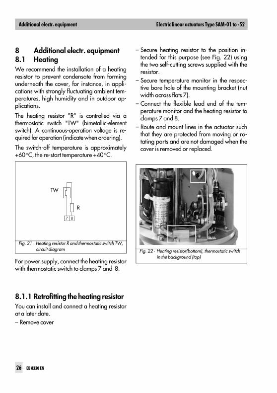
8 Additional electr. equipment8.1 HeatingWe recommend the installation of a heatingresistor to prevent condensate from formingunderneath the cover, for instance, in appli-cations with strongly fluctuating ambient tem-peratures, high humidity and in outdoor ap-plications.
The heating resistor "R" is controlled via athermostatic switch "TW" (bimetallic-elementswitch). A continuous-operation voltage is re-quired for operation (indicate when ordering).
The switch-off temperature is approximately+60°C, the re-start temperature +40°C.
For power supply, connect the heating resistorwith thermostatic switch to clamps 7 and 8.
8.1.1 Retrofitting the heating resistorYou can install and connect a heating resistorat a later date. – Remove cover
– Secure heating resistor to the position in-tended for this purpose (see Fig. 22) usingthe two self-cutting screws supplied with theresistor.
– Secure temperature monitor in the respec-tive bore hole of the mounting bracket (nutwidth across flats 7).
– Connect the flexible lead end of the tem-perature monitor and the heating resistor toclamps 7 and 8.
– Route and mount lines in the actuator suchthat they are protected from moving or ro-tating parts and are not damaged when thecover is removed or replaced.
7 8
R
TW
Fig. 21 ⋅ Heating resistor R and thermostatic switch TW, circuit diagram Fig. 22 ⋅ Heating resistor(bottom), thermostatic switch
in the background (top)
!
&& - "#
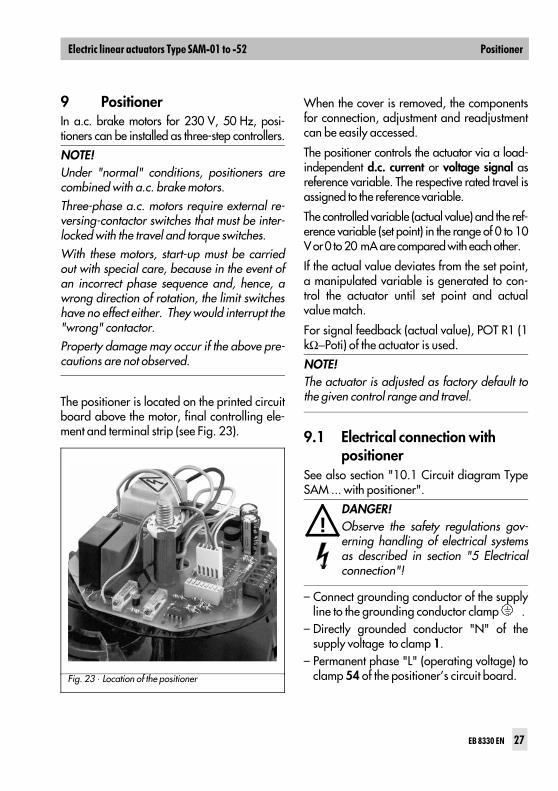
9 PositionerIn a.c. brake motors for 230 V, 50 Hz, posi-tioners can be installed as three-step controllers.
The positioner is located on the printed circuitboard above the motor, final controlling ele-ment and terminal strip (see Fig. 23).
When the cover is removed, the componentsfor connection, adjustment and readjustmentcan be easily accessed.
The positioner controls the actuator via a load-independent d.c. current or voltage signal asreference variable. The respective rated travel isassigned to the reference variable.
The controlled variable (actual value) and the ref-erence variable (set point) in the range of 0 to 10V or 0 to 20 mA are compared with each other.
If the actual value deviates from the set point,a manipulated variable is generated to con-trol the actuator until set point and actualvalue match.
For signal feedback (actual value), POT R1 (1kΩ−Poti) of the actuator is used.
9.1 Electrical connection with positioner
See also section "10.1 Circuit diagram TypeSAM ... with positioner".
– Connect grounding conductor of the supplyline to the grounding conductor clamp .
– Directly grounded conductor "N" of thesupply voltage to clamp 1.
– Permanent phase "L" (operating voltage) toclamp 54 of the positioner’s circuit board.
!
NOTE!Under "normal" conditions, positioners arecombined with a.c. brake motors.Three-phase a.c. motors require external re-versing-contactor switches that must be inter-locked with the travel and torque switches.With these motors, start-up must be carriedout with special care, because in the event ofan incorrect phase sequence and, hence, awrong direction of rotation, the limit switcheshave no effect either. They would interrupt the"wrong" contactor.Property damage may occur if the above pre-cautions are not observed.
Fig. 23 ⋅ Location of the positioner
NOTE!The actuator is adjusted as factory default tothe given control range and travel.
DANGER!Observe the safety regulations gov-erning handling of electrical systemsas described in section "5 Electricalconnection"!
$
9.1.1 Connecting the control lineFor the connection of the lines, refer to section"5.2 Establishing the connection ".
Control voltage 0 (2) to 10 V:(−) Clamp 57 (+) Clamp 56
Control current 0 (4) to 20 mA:(−) Clamp 57 (+) Clamp 59
10 V (20 mA) = Actuator stem up ("OPEN")
2 V (4 mA) = Actuator stem down ("CLOSED")
9.1.2 Feedback signalYou can measure the actual value either as:– Voltage 0 (2) to 10 V
(−) Clamp 58 (+) Clamp 61 or
– Current 0 (4) to 20 mA:(−) Clamp 58 (+) Clamp 60
The output signal always corresponds to theinput signal at a tolerance of approx. 200 mVor 0.2 mA compared to the input.
The feedback signal is in the same direction,i.e. an increasing input signal (set point) alsocauses an increasing feedback signal.
The feedback signal must not be adjusted andis not electrically isolated from the input.
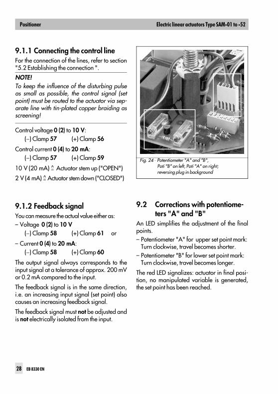
9.2 Corrections with potentiome-ters "A" and "B"
An LED simplifies the adjustment of the finalpoints.– Potentiometer "A" for upper set point mark:
Turn clockwise, travel becomes shorter.– Potentiometer "B" for lower set point mark:
Turn clockwise, travel becomes longer.
The red LED signalizes: actuator in final posi-tion, no manipulated variable is generated,the set point has been reached.
Fig. 24 ⋅ Potentiometer "A" and "B", Poti "B" on left, Poti "A" on right; reversing plug in background
NOTE!To keep the influence of the disturbing pulseas small as possible, the control signal (setpoint) must be routed to the actuator via sep-arate line with tin-plated copper braiding asscreening!
9.3 ReversingBy turning the reversing plug (see Fig. 24), thedirection of rotation is reversed by 180 de-grees, i. e. the motor’s direction of travel isreversed with regard to the set point.– Disconnect actuator from the supply voltage.– Remove reversing plug, turn by 180 de-
grees and plug back in.– Reconnect actuator to supply voltage .– If required, correct with Poti "A" or "B".
9.4 Sequential mode You can also operate the positioner in sequen-tial mode. The lowest range is 2 V or 4 mA.
The position of the sequence within the rangeof 0 to 10 V or 4 to 20 mA is arbitrary. Usethe trimming potentiometers "A" and "B" toadjust the respective final value.
The upper range value must be adjusted first.
Use the potentiometer "A" to adjust the upperrange sequential mark. Use the potentiometer"B" to adjust the lower range sequential mark.
10 Maintenance and service
The gearing and the actuator stem must be re-lubricated after approx. 200,000 doublestrokes. We recommend the following lubri-cants: – Standard and tropics version:
Klüber Microlube GL 261– Oxygen version:
BARRIERTA L55/3 OX.
Do not attempt to repair the linear actuator onsite. Defective actuators must be sent togetherwith a fault report including the product num-ber to SAMSON AG.
!WARNING!Before you remove the cover andprior to any maintenance and adjust-ments, disconnect the supply voltageto the actuator. Ensure that the actuator cannot beswitched on again accidentally!
'
& .
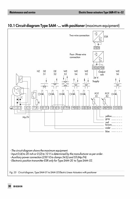
10.1 Circuit diagram Type SAM -... with positioner (maximum equipment)
- The circuit diagram shows the maximum equipment.- Input 0 (4) to 20 mA or 0 (2) to 10 V is determined by the manufacturer as per order.- Auxiliary power connection (230 V) to clamps 54 (L) and 55 (Mp/N).- Electronic position transmitter ESR only for Type SAM-20 to Type SAM-52.
Four-/three-wireconnection
Output mA
gray
brownvioletblue
Mp/N
1~
C
R
10 11121 2 3 7 84 5 16 17181314 15 192021 252627
25+ – –
+ – –
262728
25 26
282930 313233222324
DES1
HZ DES2
WES3
WES4
WES5
POTR1
POTR2
WES6
ESRTwo-wire connection
24 V−
Supply
yellow
red
Fig. 25 ⋅ Circuit diagram, Type SAM-01 to SAM-52 Electric Linear Actuators with positioner
& .
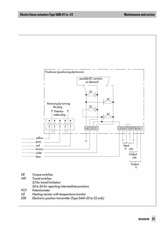
Potentio-meter plug
Output V
54
L1
5352 51
RC
RC
RC
RC
55 5657
+ – – +
585960 61
DE Torque switchesWE Travel switches
S3 for travel limitationS4 to S6 for reporting intermediate positions
POT PotentiometerHZ Heating resistor with temperature monitorESR Electronic position transmitter (Type SAM-20 to 52 only)
Positioner (positioning electronics)
possible RC variants on demand
Reversing by turning the plug
Input V mA
Output mA
brown violet blue
yellow gray red
& .

S /C
D 0
7.99SAMSON AG ⋅ MESS- UND REGELTECHNIK
Weismüllerstraße 3 ⋅ D-60314 Frankfurt am MainTelefon (0 69) 4 00 90 ⋅ Telefax (0 69) 4 00 95 07Internet: http://www.samson.de
EB 8330 EN