Embed Size (px)
Citation preview
Electropneumatic PositionerType 3730-2
Mounting andOperating Instructions
EB 8384-2 ENFirmware version 1.2xEdition December 2004
Fig. 1 · Type 3730-2
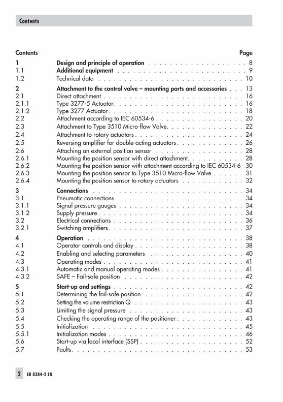
Contents Page
1 Design and principle of operation . . . . . . . . . . . . . . . . . . . 81.1 Additional equipment . . . . . . . . . . . . . . . . . . . . . . . . . 91.2 Technical data . . . . . . . . . . . . . . . . . . . . . . . . . . . . 10
2 Attachment to the control valve – mounting parts and accessories . . . 132.1 Direct attachment . . . . . . . . . . . . . . . . . . . . . . . . . . . 162.1.1 Type 3277-5 Actuator. . . . . . . . . . . . . . . . . . . . . . . . . 162.1.2 Type 3277 Actuator . . . . . . . . . . . . . . . . . . . . . . . . . . 182.2 Attachment according to IEC 60534-6 . . . . . . . . . . . . . . . . . 202.3 Attachment to Type 3510 Micro-flow Valve. . . . . . . . . . . . . . . 222.4 Attachment to rotary actuators . . . . . . . . . . . . . . . . . . . . . 242.5 Reversing amplifier for double-acting actuators . . . . . . . . . . . . . 262.6 Attaching an external position sensor . . . . . . . . . . . . . . . . . 282.6.1 Mounting the position sensor with direct attachment. . . . . . . . . . . 282.6.2 Mounting the position sensor with attachment according to IEC 60534-6 302.6.3 Mounting the position sensor to Type 3510 Micro-flow Valve . . . . . . 312.6.4 Mounting the position sensor to rotary actuators . . . . . . . . . . . . 32
3 Connections . . . . . . . . . . . . . . . . . . . . . . . . . . . . . 343.1 Pneumatic connections . . . . . . . . . . . . . . . . . . . . . . . . 343.1.1 Signal pressure gauges . . . . . . . . . . . . . . . . . . . . . . . . 343.1.2 Supply pressure . . . . . . . . . . . . . . . . . . . . . . . . . . . . 343.2 Electrical connections . . . . . . . . . . . . . . . . . . . . . . . . . 363.2.1 Switching amplifiers . . . . . . . . . . . . . . . . . . . . . . . . . . 37
4 Operation . . . . . . . . . . . . . . . . . . . . . . . . . . . . . . 384.1 Operator controls and display . . . . . . . . . . . . . . . . . . . . . 384.2 Enabling and selecting parameters . . . . . . . . . . . . . . . . . . 404.3 Operating modes . . . . . . . . . . . . . . . . . . . . . . . . . . . 414.3.1 Automatic and manual operating modes . . . . . . . . . . . . . . . . 414.3.2 SAFE – Fail-safe position . . . . . . . . . . . . . . . . . . . . . . . 42
5 Start-up and settings . . . . . . . . . . . . . . . . . . . . . . . . . 425.1 Determining the fail-safe position . . . . . . . . . . . . . . . . . . . 425.2 Setting the volume restriction Q . . . . . . . . . . . . . . . . . . . . . 435.3 Limiting the signal pressure . . . . . . . . . . . . . . . . . . . . . . 435.4 Checking the operating range of the positioner . . . . . . . . . . . . . 435.5 Initialization . . . . . . . . . . . . . . . . . . . . . . . . . . . . . 455.5.1 Initialization modes . . . . . . . . . . . . . . . . . . . . . . . . . . 465.6 Start-up via local interface (SSP) . . . . . . . . . . . . . . . . . . . . 525.7 Faults . . . . . . . . . . . . . . . . . . . . . . . . . . . . . . . . . 53
2 EB 8384-2 EN
Contents
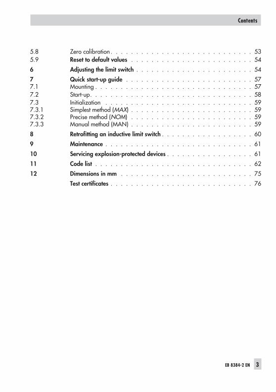
5.8 Zero calibration . . . . . . . . . . . . . . . . . . . . . . . . . . . . 535.9 Reset to default values . . . . . . . . . . . . . . . . . . . . . . . . 54
6 Adjusting the limit switch . . . . . . . . . . . . . . . . . . . . . . . 54
7 Quick start-up guide . . . . . . . . . . . . . . . . . . . . . . . . . 577.1 Mounting . . . . . . . . . . . . . . . . . . . . . . . . . . . . . . . 577.2 Start-up. . . . . . . . . . . . . . . . . . . . . . . . . . . . . . . . 587.3 Initialization . . . . . . . . . . . . . . . . . . . . . . . . . . . . . 597.3.1 Simplest method (MAX) . . . . . . . . . . . . . . . . . . . . . . . . 597.3.2 Precise method (NOM) . . . . . . . . . . . . . . . . . . . . . . . . 597.3.3 Manual method (MAN) . . . . . . . . . . . . . . . . . . . . . . . . 59
8 Retrofitting an inductive limit switch . . . . . . . . . . . . . . . . . . 60
9 Maintenance . . . . . . . . . . . . . . . . . . . . . . . . . . . . . 61
10 Servicing explosion-protected devices . . . . . . . . . . . . . . . . . 61
11 Code list . . . . . . . . . . . . . . . . . . . . . . . . . . . . . . . 62
12 Dimensions in mm . . . . . . . . . . . . . . . . . . . . . . . . . . 75
Test certificates . . . . . . . . . . . . . . . . . . . . . . . . . . . . 76
EB 8384-2 EN 3
Contents
4 EB 8384-2 EN
Safety instructions
General safety instructions
The positioner may only be assembled, started up or operated by trainedand experienced personnel familiar with the product.According to these mounting and operating instructions, trained personnel isreferred to as individuals who are able to judge the work they are assignedto and recognize possible dangers due to their specialized training, theirknowledge and experience as well as their knowledge of the relevantstandards.
Explosion-protected versions of this positioner may only be operated bypersonnel who have undergone special training or instructions or who areauthorized to work on explosion-protected devices in hazardous areas.Refer to section 10 on Servicing explosion-protected versions.
Any hazards that could be caused by the process medium, the operatingpressure, the signal pressure or by moving parts of the control valve are tobe prevented by means of the appropriate measures.
If inadmissible motions or forces are produced in the actuator as a result ofthe supply pressure level, it must be restricted by means of a suitable supplypressure reducing station.
Proper shipping and appropriate storage are assumed.
Note! The device with a CE marking fulfils the requirements of the Directives94/9/EC (ATEX) and 89/336/EEC (EMC).The declaration of conformity can be viewed and downloaded on theInternet at http://www.samson.de.
EB 8384-2 EN 5
Versions
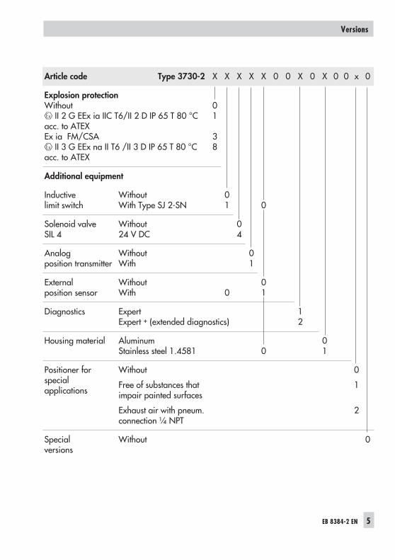
Article code Type 3730-2 X X X X X 0 0 X 0 X 0 0 x 0
Explosion protectionWithout
II 2 G EEx ia IIC T6/II 2 D IP 65 T 80 °Cacc. to ATEXEx ia FM/CSA
II 3 G EEx na II T6 /II 3 D IP 65 T 80 °Cacc. to ATEX
01
38
Additional equipment
Inductivelimit switch
WithoutWith Type SJ 2-SN
01 0
Solenoid valveSIL 4
Without24 V DC
04
Analogposition transmitter
WithoutWith
01
Externalposition sensor
WithoutWith 0
01
Diagnostics ExpertExpert + (extended diagnostics)
12
Housing material AluminumStainless steel 1.4581 0
01
Positioner forspecialapplications
Without
Free of substances thatimpair painted surfaces
Exhaust air with pneum.connection ¼ NPT
0
1
2
Specialversions
Without 0
6 EB 8384-2 EN
Firmware modification
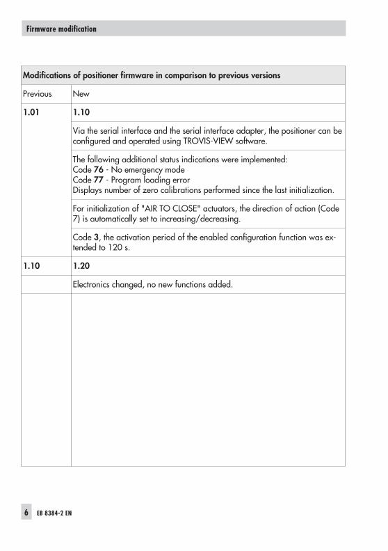
Modifications of positioner firmware in comparison to previous versions
Previous New
1.01 1.10
Via the serial interface and the serial interface adapter, the positioner can beconfigured and operated using TROVIS-VIEW software.
The following additional status indications were implemented:Code 76 - No emergency modeCode 77 - Program loading errorDisplays number of zero calibrations performed since the last initialization.
For initialization of "AIR TO CLOSE" actuators, the direction of action (Code7) is automatically set to increasing/decreasing.
Code 3, the activation period of the enabled configuration function was ex-tended to 120 s.
1.10 1.20
Electronics changed, no new functions added.
EB 8384-2 EN 7
Firmware modification
1 Design and principle ofoperation
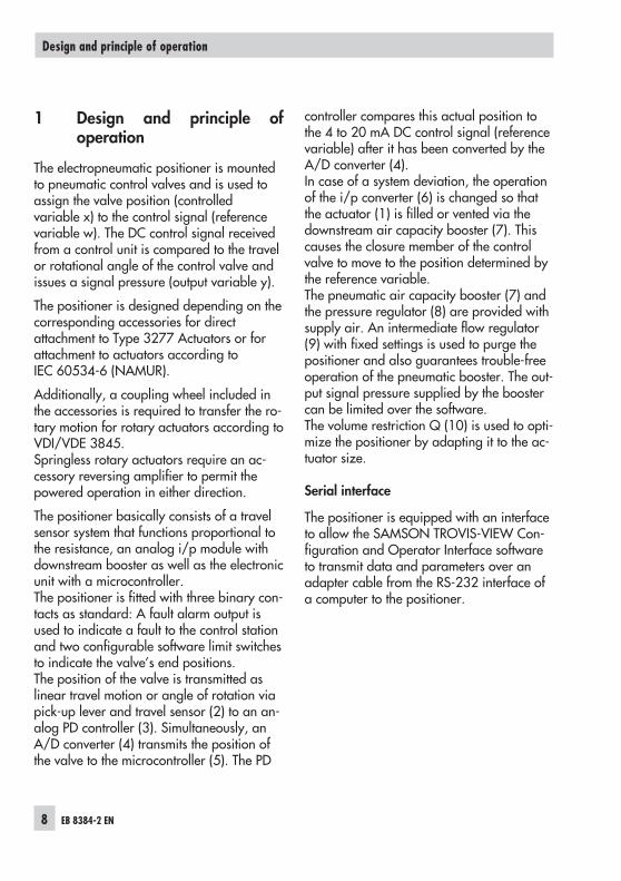
The electropneumatic positioner is mountedto pneumatic control valves and is used toassign the valve position (controlledvariable x) to the control signal (referencevariable w). The DC control signal receivedfrom a control unit is compared to the travelor rotational angle of the control valve andissues a signal pressure (output variable y).
The positioner is designed depending on thecorresponding accessories for directattachment to Type 3277 Actuators or forattachment to actuators according toIEC 60534-6 (NAMUR).
Additionally, a coupling wheel included inthe accessories is required to transfer the ro-tary motion for rotary actuators according toVDI/VDE 3845.Springless rotary actuators require an ac-cessory reversing amplifier to permit thepowered operation in either direction.
The positioner basically consists of a travelsensor system that functions proportional tothe resistance, an analog i/p module withdownstream booster as well as the electronicunit with a microcontroller.The positioner is fitted with three binary con-tacts as standard: A fault alarm output isused to indicate a fault to the control stationand two configurable software limit switchesto indicate the valve’s end positions.The position of the valve is transmitted aslinear travel motion or angle of rotation viapick-up lever and travel sensor (2) to an an-alog PD controller (3). Simultaneously, anA/D converter (4) transmits the position ofthe valve to the microcontroller (5). The PD
controller compares this actual position tothe 4 to 20 mA DC control signal (referencevariable) after it has been converted by theA/D converter (4).In case of a system deviation, the operationof the i/p converter (6) is changed so thatthe actuator (1) is filled or vented via thedownstream air capacity booster (7). Thiscauses the closure member of the controlvalve to move to the position determined bythe reference variable.The pneumatic air capacity booster (7) andthe pressure regulator (8) are provided withsupply air. An intermediate flow regulator(9) with fixed settings is used to purge thepositioner and also guarantees trouble-freeoperation of the pneumatic booster. The out-put signal pressure supplied by the boostercan be limited over the software.The volume restriction Q (10) is used to opti-mize the positioner by adapting it to the ac-tuator size.
Serial interface
The positioner is equipped with an interfaceto allow the SAMSON TROVIS-VIEW Con-figuration and Operator Interface softwareto transmit data and parameters over anadapter cable from the RS-232 interface ofa computer to the positioner.
8 EB 8384-2 EN
Design and principle of operation
1.1 Additional equipment
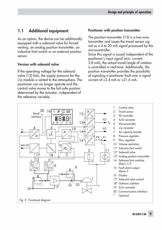
As an option, the device can be additionallyequipped with a solenoid valve for forcedventing, an analog position transmitter, aninductive limit switch or an external positionsensor.
Version with solenoid valve
If the operating voltage for the solenoidvalve (12) fails, the supply pressure for thei/p module is vented to the atmosphere. Thepositioner can no longer operate and thecontrol valve moves to the fail-safe positiondetermined by the actuator, independent ofthe reference variable.
Positioner with position transmitter
The position transmitter (13) is a two-wiretransmitter and issues the travel sensor sig-nal as a 4 to 20 mA signal processed by themicrocontroller.Since this signal is issued independent of thepositioner’s input signal (min. current3.8 mA), the actual travel/angle of rotationis controlled in real-time. Additionally, theposition transmitter provides the possibilityof signaling a positioner fault over a signalcurrent of <2.4 mA or >21.6 mA.
EB 8384-2 EN 9
Design and principle of operation
Fig. 2 · Functional diagram
1 Control valve2 Travel sensor3 PD controller4 A/D converter5 Microcontroller6 i/p converter7 Air capacity booster8 Pressure regulator9 Flow regulator10 Volume restriction11* Inductive limit switch12* Solenoid valve13* Analog position transmitter14 Software limit switches
Alarm 1/215 Fault alarm output
Alarm 316 Display17* Solenoid valve control18* Galvanic isolation19 D/A converter20 Communication interface* Optional
w
x
Q
%S
mm
GG
PD
SerialInterface
162013
15A2
A3
A1
112
4 195
312
6
7
8
10
1
14
14
w
xy
24V DC
9
17 18
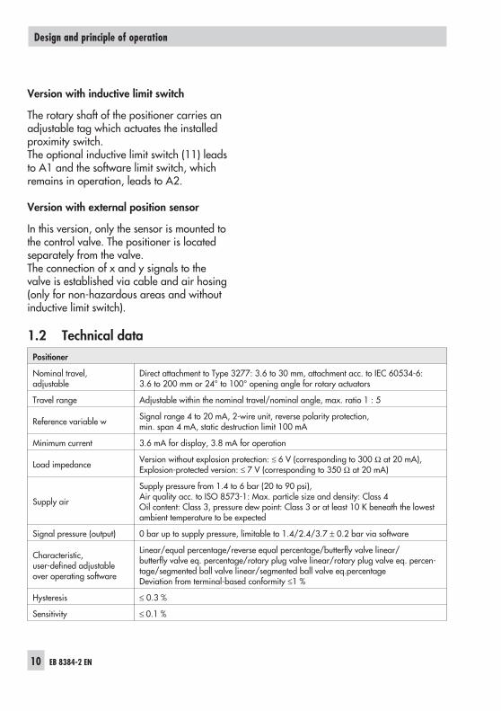
Version with inductive limit switch
The rotary shaft of the positioner carries anadjustable tag which actuates the installedproximity switch.The optional inductive limit switch (11) leadsto A1 and the software limit switch, whichremains in operation, leads to A2.
Version with external position sensor
In this version, only the sensor is mounted tothe control valve. The positioner is locatedseparately from the valve.The connection of x and y signals to thevalve is established via cable and air hosing(only for non-hazardous areas and withoutinductive limit switch).
1.2 Technical data
10 EB 8384-2 EN
Design and principle of operation
Positioner
Nominal travel,adjustable
Direct attachment to Type 3277: 3.6 to 30 mm, attachment acc. to IEC 60534-6:3.6 to 200 mm or 24° to 100° opening angle for rotary actuators
Travel range Adjustable within the nominal travel/nominal angle, max. ratio 1 : 5
Reference variable w Signal range 4 to 20 mA, 2-wire unit, reverse polarity protection,min. span 4 mA, static destruction limit 100 mA
Minimum current 3.6 mA for display, 3.8 mA for operation
Load impedance Version without explosion protection: ≤ 6 V (corresponding to 300 Ω at 20 mA),Explosion-protected version: ≤ 7 V (corresponding to 350 Ω at 20 mA)
Supply air
Supply pressure from 1.4 to 6 bar (20 to 90 psi),Air quality acc. to ISO 8573-1: Max. particle size and density: Class 4Oil content: Class 3, pressure dew point: Class 3 or at least 10 K beneath the lowestambient temperature to be expected
Signal pressure (output) 0 bar up to supply pressure, limitable to 1.4/2.4/3.7 ± 0.2 bar via software
Characteristic,user-defined adjustableover operating software
Linear/equal percentage/reverse equal percentage/butterfly valve linear/butterfly valve eq. percentage/rotary plug valve linear/rotary plug valve eq. percen-tage/segmented ball valve linear/segmented ball valve eq.percentageDeviation from terminal-based conformity ≤1 %
Hysteresis ≤ 0.3 %
Sensitivity ≤ 0.1 %
EB 8384-2 EN 11
Design and principle of operation
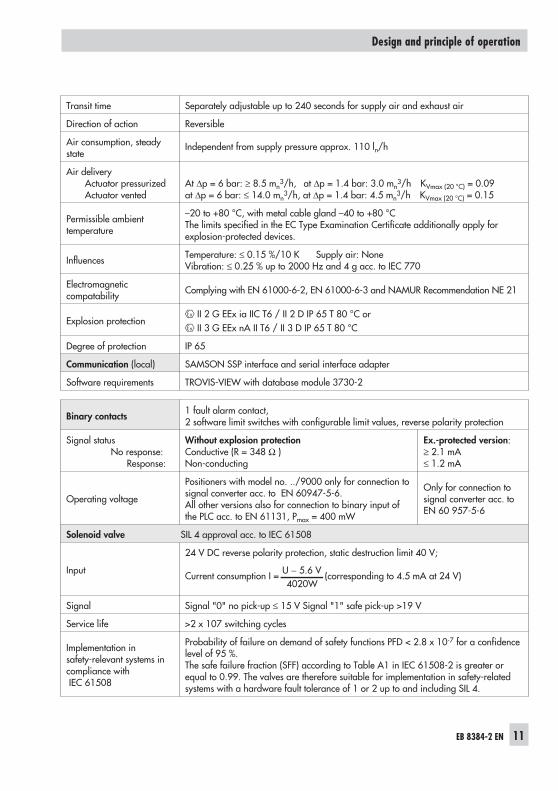
Transit time Separately adjustable up to 240 seconds for supply air and exhaust air
Direction of action Reversible
Air consumption, steadystate
Independent from supply pressure approx. 110 ln/h
Air deliveryActuator pressurizedActuator vented
At ∆p = 6 bar: ≥ 8.5 mn3/h, at ∆p = 1.4 bar: 3.0 mn
3/h KVmax (20 °C) = 0.09at ∆p = 6 bar: ≤ 14.0 mn
3/h, at ∆p = 1.4 bar: 4.5 mn3/h KVmax (20 °C) = 0.15
Permissible ambienttemperature
–20 to +80 °C, with metal cable gland –40 to +80 °CThe limits specified in the EC Type Examination Certificate additionally apply forexplosion-protected devices.
Influences Temperature: ≤ 0.15 %/10 K Supply air: NoneVibration: ≤ 0.25 % up to 2000 Hz and 4 g acc. to IEC 770
Electromagneticcompatability Complying with EN 61000-6-2, EN 61000-6-3 and NAMUR Recommendation NE 21
Explosion protectionII 2 G EEx ia IIC T6 / II 2 D IP 65 T 80 °C orII 3 G EEx nA II T6 / II 3 D IP 65 T 80 °C
Degree of protection IP 65
Communication (local) SAMSON SSP interface and serial interface adapter
Software requirements TROVIS-VIEW with database module 3730-2
Binary contacts 1 fault alarm contact,2 software limit switches with configurable limit values, reverse polarity protection
Signal statusNo response:
Response:
Without explosion protectionConductive (R = 348 Ω )Non-conducting
Ex.-protected version:≥ 2.1 mA≤ 1.2 mA
Operating voltage
Positioners with model no. ../9000 only for connection tosignal converter acc. to EN 60947-5-6.All other versions also for connection to binary input ofthe PLC acc. to EN 61131, Pmax = 400 mW
Only for connection tosignal converter acc. toEN 60 957-5-6
Solenoid valve SIL 4 approval acc. to IEC 61508
Input
24 V DC reverse polarity protection, static destruction limit 40 V;
Current consumption I = U 5.6 V4020W− (corresponding to 4.5 mA at 24 V)
Signal Signal "0" no pick-up ≤ 15 V Signal "1" safe pick-up >19 V
Service life >2 x 10⁷ switching cycles
Implementation insafety-relevant systems incompliance withIEC 61508
Probability of failure on demand of safety functions PFD < 2.8 x 10⁻⁷ for a confidencelevel of 95 %.The safe failure fraction (SFF) according to Table A1 in IEC 61508-2 is greater orequal to 0.99. The valves are therefore suitable for implementation in safety-relatedsystems with a hardware fault tolerance of 1 or 2 up to and including SIL 4.
12 EB 8384-2 EN
Design and principle of operation
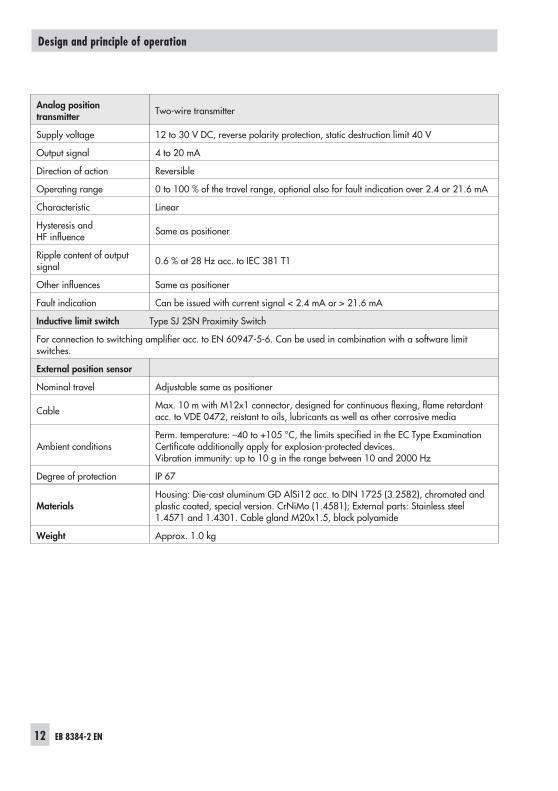
Analog positiontransmitter Two-wire transmitter
Supply voltage 12 to 30 V DC, reverse polarity protection, static destruction limit 40 V
Output signal 4 to 20 mA
Direction of action Reversible
Operating range 0 to 100 % of the travel range, optional also for fault indication over 2.4 or 21.6 mA
Characteristic Linear
Hysteresis andHF influence Same as positioner
Ripple content of outputsignal 0.6 % at 28 Hz acc. to IEC 381 T1
Other influences Same as positioner
Fault indication Can be issued with current signal < 2.4 mA or > 21.6 mA
Inductive limit switch Type SJ 2SN Proximity Switch
For connection to switching amplifier acc. to EN 60947-5-6. Can be used in combination with a software limitswitches.
External position sensor
Nominal travel Adjustable same as positioner
Cable Max. 10 m with M12x1 connector, designed for continuous flexing, flame retardantacc. to VDE 0472, reistant to oils, lubricants as well as other corrosive media
Ambient conditionsPerm. temperature: –40 to +105 °C, the limits specified in the EC Type ExaminationCertificate additionally apply for explosion-protected devices.Vibration immunity: up to 10 g in the range between 10 and 2000 Hz
Degree of protection IP 67
MaterialsHousing: Die-cast aluminum GD AlSi12 acc. to DIN 1725 (3.2582), chromated andplastic coated, special version. CrNiMo (1.4581); External parts: Stainless steel1.4571 and 1.4301. Cable gland M20x1.5, black polyamide
Weight Approx. 1.0 kg
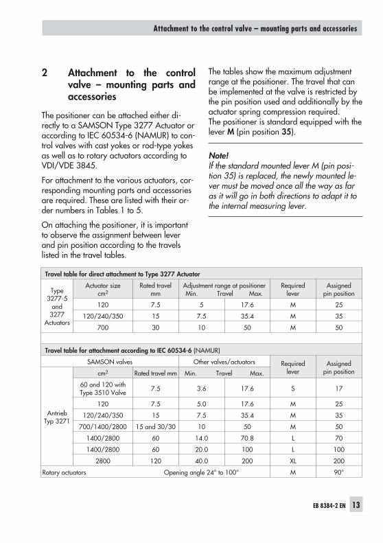
2 Attachment to the controlvalve – mounting parts andaccessories
The positioner can be attached either di-rectly to a SAMSON Type 3277 Actuator oraccording to IEC 60534-6 (NAMUR) to con-trol valves with cast yokes or rod-type yokesas well as to rotary actuators according toVDI/VDE 3845.
For attachment to the various actuators, cor-responding mounting parts and accessoriesare required. These are listed with their or-der numbers in Tables 1 to 5.
On attaching the positioner, it is importantto observe the assignment between leverand pin position according to the travelslisted in the travel tables.
The tables show the maximum adjustmentrange at the positioner. The travel that canbe implemented at the valve is restricted bythe pin position used and additionally by theactuator spring compression required.The positioner is standard equipped with thelever M (pin position 35).
Note!If the standard mounted lever M (pin posi-tion 35) is replaced, the newly mounted le-ver must be moved once all the way as faras it will go in both directions to adapt it tothe internal measuring lever.
EB 8384-2 EN 13
Attachment to the control valve – mounting parts and accessories
Travel table for direct attachment to Type 3277 Actuator
Type3277-5
and3277
Actuators
Actuator sizecm2
Rated travelmm
Adjustment range at positionerMin. Travel Max.
Requiredlever
Assignedpin position
120 7.5 5 17.6 M 25
120/240/350 15 7.5 35.4 M 35
700 30 10 50 M 50
Travel table for attachment according to IEC 60534-6 (NAMUR)
SAMSON valves Other valves/actuators Requiredlever
Assignedpin position
AntriebTyp 3271
cm2 Rated travel mm Min. Travel Max.
60 and 120 withType 3510 Valve 7.5 3.6 17.6 S 17
120 7.5 5.0 17.6 M 25
120/240/350 15 7.5 35.4 M 35
700/1400/2800 15 and 30/30 10 50 M 50
1400/2800 60 14.0 70.8 L 70
1400/2800 60 20.0 100 L 100
2800 120 40.0 200 XL 200
Rotary actuators Opening angle 24° to 100° M 90°
14 EB 8384-2 EN
Attachment to the control valve – mounting parts and accessories
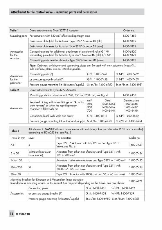
Table 3 Attachment to NAMUR ribs or control valves with rod-type yokes (rod diameter Ø 35 mm or smaller)according to IEC 60534-6, see Fig. 5
Travel in mm Lever For actuators Order no.
7.5 S Type 3271-5 Actuator with 60/120 cm2 on Type 3510Valve, see Fig. 6 1400-7457
5 to 50 Without (lever M onbasic model)
Actuators from other manufacturers and Type 3271 with120 to 700 cm2 1400-7454
14 to 100 L Actuators f. other manufacturers and Type 3271 w. 1400 cm2 1400-7455
40 to 200 XL Actuators from other manufacturers and Type 3271 with2800 cm2, 120 mm travel 1400-7456
30 or 60 L Type 3271 Actuator with 2800 cm2 and 30 or 60 mm travel 1400-7466
Mounting brackets for Emerson and Masoneilan linear actuatorsIn addition, a mounting kit acc. to IEC 60534-6 is required depending on the travel. See row above. 1400-6771
Accessories
Connecting plate G ¼: 1400-7461 ¼ NPT : 1400-7462
or pressure gauge bracket (7) G ¼: 1400-7458 ¼ NPT: 1400-7459
Pressure gauge mounting kit (output/supply) St.st./Bs: 1400-6950 St.st./St.st.: 1400-6951
Table 1 Direct attachment to Type 3277-5 Actuator Order no.
Mounting parts For actuators with 120 cm2 effective diaphragm area 1400-7452
Accessoriesfor theactuator
Switchover plate (old) for Actuator Type 3277-5xxxxxx.00 (old) 1400-6819
Switchover plate new for Actuator Type 3277-5xxxxxx.01 (new) 1400-6822
Connecting plate for additional attachment of a solenoid valve G 1/8Connecting plate (old) for Actuator Type 3277-5xxxxxx.00 (old) 1/8 NPT
1400-68201400-6821
Connecting plate new for Actuator Type 3277-5xxxxxx.01 (new) 1400-6823
Note: Only new switchover and connecting plates can be used with new actuators (Index 01).Old and new plates are not interchangeable.
Accessoriesfor thepositioner
Connecting plate (6) G ¼: 1400-7461 ¼ NPT: 1400-7462
or pressure gauge bracket (7) G ¼: 1400-7458 ¼ NPT: 1400-7459
Pressure gauge mounting kit (8) (output/supply) St. st./Bs: 1400-6950 St. st./St. st.: 1400-6951
Table 2 Direct attachment to Type 3277 Actuator
Accessories
Mounting parts for actuators with 240, 350 and 700 cm2, see Fig. 4 1400-7453
Required piping with screw fittings for "Actuatorstem retracts" or when the top diaphragmchamber is filled with air
cm2 Steel Stainless steel240 1400-6444 1400-6445350 1400-6446 1400-6447700 1400-6448 1400-6449
Connection block with seals and screw G ¼: 1400-8811 ¼ NPT: 1400-8812
Pressure gauge mounting kit (output and supply) St.st./Bs: 1400-6950 St.st/St.st.: 1400-6951
EB 8384-2 EN 15
Attachment to the control valve – mounting parts and accessories
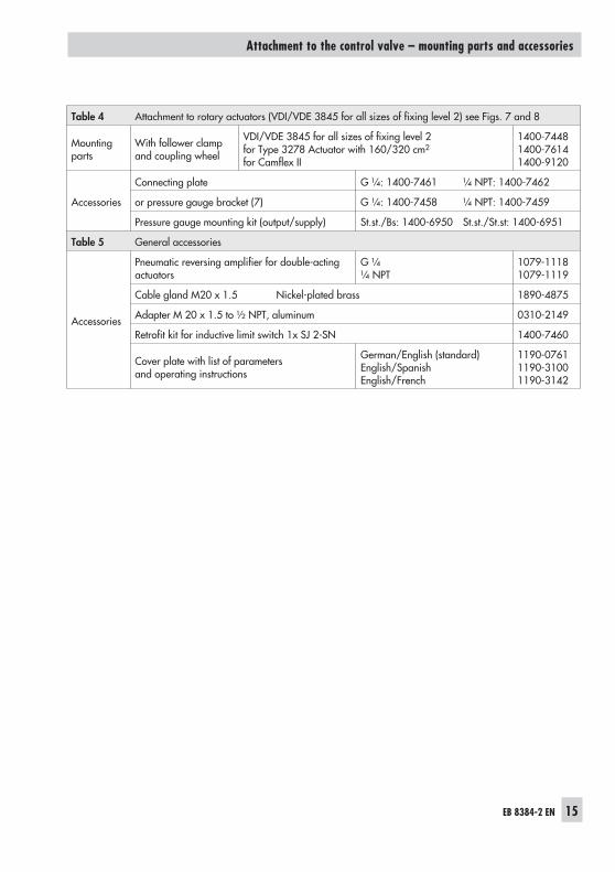
Table 4 Attachment to rotary actuators (VDI/VDE 3845 for all sizes of fixing level 2) see Figs. 7 and 8
Mountingparts
With follower clampand coupling wheel
VDI/VDE 3845 for all sizes of fixing level 2for Type 3278 Actuator with 160/320 cm2
for Camflex II
1400-74481400-76141400-9120
Accessories
Connecting plate G ¼: 1400-7461 ¼ NPT: 1400-7462
or pressure gauge bracket (7) G ¼: 1400-7458 ¼ NPT: 1400-7459
Pressure gauge mounting kit (output/supply) St.st./Bs: 1400-6950 St.st./St.st: 1400-6951
Table 5 General accessories
Accessories
Pneumatic reversing amplifier for double-actingactuators
G ¼¼ NPT
1079-11181079-1119
Cable gland M20 x 1.5 Nickel-plated brass 1890-4875
Adapter M 20 x 1.5 to ½ NPT, aluminum 0310-2149
Retrofit kit for inductive limit switch 1x SJ 2-SN 1400-7460
Cover plate with list of parametersand operating instructions
German/English (standard)English/SpanishEnglish/French
1190-07611190-31001190-3142
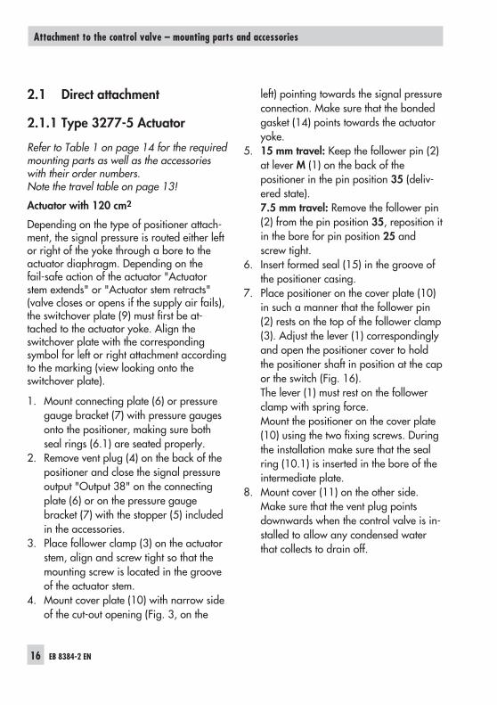
2.1 Direct attachment
2.1.1 Type 3277-5 Actuator
Refer to Table 1 on page 14 for the requiredmounting parts as well as the accessorieswith their order numbers.Note the travel table on page 13!
Actuator with 120 cm2
Depending on the type of positioner attach-ment, the signal pressure is routed either leftor right of the yoke through a bore to theactuator diaphragm. Depending on thefail-safe action of the actuator "Actuatorstem extends" or "Actuator stem retracts"(valve closes or opens if the supply air fails),the switchover plate (9) must first be at-tached to the actuator yoke. Align theswitchover plate with the correspondingsymbol for left or right attachment accordingto the marking (view looking onto theswitchover plate).
1. Mount connecting plate (6) or pressuregauge bracket (7) with pressure gaugesonto the positioner, making sure bothseal rings (6.1) are seated properly.
2. Remove vent plug (4) on the back of thepositioner and close the signal pressureoutput "Output 38" on the connectingplate (6) or on the pressure gaugebracket (7) with the stopper (5) includedin the accessories.
3. Place follower clamp (3) on the actuatorstem, align and screw tight so that themounting screw is located in the grooveof the actuator stem.
4. Mount cover plate (10) with narrow sideof the cut-out opening (Fig. 3, on the
left) pointing towards the signal pressureconnection. Make sure that the bondedgasket (14) points towards the actuatoryoke.
5. 15 mm travel: Keep the follower pin (2)at lever M (1) on the back of thepositioner in the pin position 35 (deliv-ered state).7.5 mm travel: Remove the follower pin(2) from the pin position 35, reposition itin the bore for pin position 25 andscrew tight.
6. Insert formed seal (15) in the groove ofthe positioner casing.
7. Place positioner on the cover plate (10)in such a manner that the follower pin(2) rests on the top of the follower clamp(3). Adjust the lever (1) correspondinglyand open the positioner cover to holdthe positioner shaft in position at the capor the switch (Fig. 16).The lever (1) must rest on the followerclamp with spring force.Mount the positioner on the cover plate(10) using the two fixing screws. Duringthe installation make sure that the sealring (10.1) is inserted in the bore of theintermediate plate.
8. Mount cover (11) on the other side.Make sure that the vent plug pointsdownwards when the control valve is in-stalled to allow any condensed waterthat collects to drain off.
16 EB 8384-2 EN
Attachment to the control valve – mounting parts and accessories
EB 8384-2 EN 17
Attachment to the control valve – mounting parts and accessories
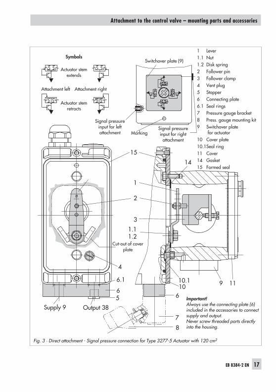
Fig. 3 · Direct attachment - Signal pressure connection for Type 3277-5 Actuator with 120 cm2
9 11
Supply 9 Output 38
56
4
7
61010.1
3
2
1
15
6.1
1.11.2
14
8
1 Lever1.1 Nut1.2 Disk spring2 Follower pin3 Follower clamp4 Vent plug5 Stopper6 Connecting plate6.1 Seal rings7 Pressure gauge bracket8 Press. gauge mounting kit9 Switchover plate
for actuator10 Cover plate10.1Seal ring11 Cover14 Gasket15 Formed seal
Important!Always use the connecting plate (6)included in the accessories to connectsupply and output.Never screw threaded parts directlyinto the housing.
Symbols
Actuator stemextends
Attachment left Attachment right
Actuator stemretracts
Switchover plate (9)
Signal pressureinput for right
attachmentMarking
Cut-out of coverplate
Signal pressureinput for leftattachment
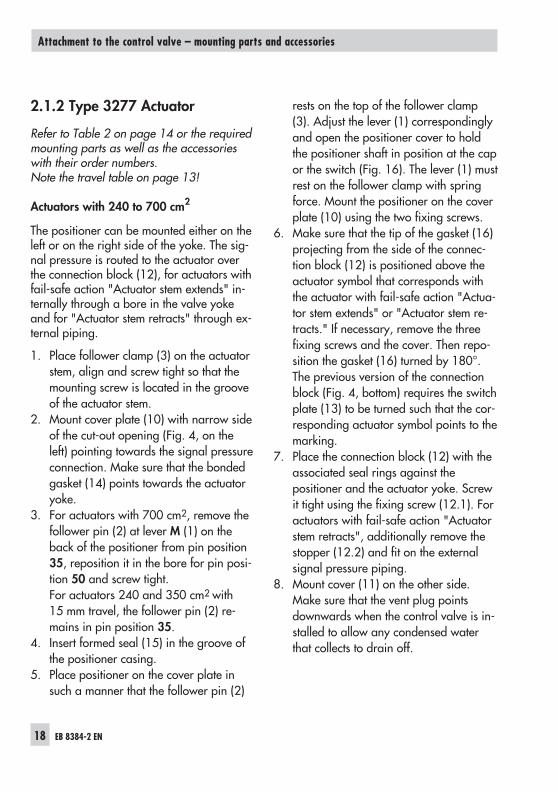
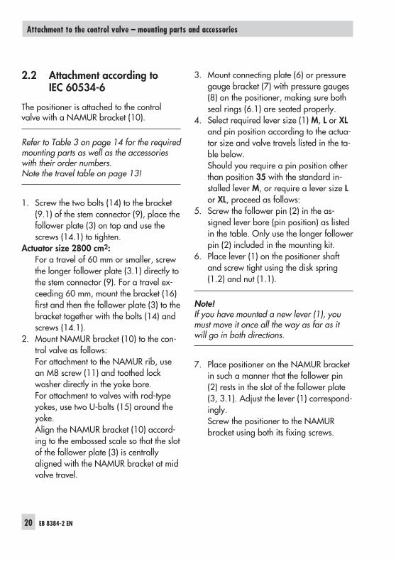
2.1.2 Type 3277 Actuator
Refer to Table 2 on page 14 or the requiredmounting parts as well as the accessorieswith their order numbers.Note the travel table on page 13!
Actuators with 240 to 700 cm2
The positioner can be mounted either on theleft or on the right side of the yoke. The sig-nal pressure is routed to the actuator overthe connection block (12), for actuators withfail-safe action "Actuator stem extends" in-ternally through a bore in the valve yokeand for "Actuator stem retracts" through ex-ternal piping.
1. Place follower clamp (3) on the actuatorstem, align and screw tight so that themounting screw is located in the grooveof the actuator stem.
2. Mount cover plate (10) with narrow sideof the cut-out opening (Fig. 4, on theleft) pointing towards the signal pressureconnection. Make sure that the bondedgasket (14) points towards the actuatoryoke.
3. For actuators with 700 cm2, remove thefollower pin (2) at lever M (1) on theback of the positioner from pin position35, reposition it in the bore for pin posi-tion 50 and screw tight.For actuators 240 and 350 cm2 with15 mm travel, the follower pin (2) re-mains in pin position 35.
4. Insert formed seal (15) in the groove ofthe positioner casing.
5. Place positioner on the cover plate insuch a manner that the follower pin (2)
rests on the top of the follower clamp(3). Adjust the lever (1) correspondinglyand open the positioner cover to holdthe positioner shaft in position at the capor the switch (Fig. 16). The lever (1) mustrest on the follower clamp with springforce. Mount the positioner on the coverplate (10) using the two fixing screws.
6. Make sure that the tip of the gasket (16)projecting from the side of the connec-tion block (12) is positioned above theactuator symbol that corresponds withthe actuator with fail-safe action "Actua-tor stem extends" or "Actuator stem re-tracts." If necessary, remove the threefixing screws and the cover. Then repo-sition the gasket (16) turned by 180°.The previous version of the connectionblock (Fig. 4, bottom) requires the switchplate (13) to be turned such that the cor-responding actuator symbol points to themarking.
7. Place the connection block (12) with theassociated seal rings against thepositioner and the actuator yoke. Screwit tight using the fixing screw (12.1). Foractuators with fail-safe action "Actuatorstem retracts", additionally remove thestopper (12.2) and fit on the externalsignal pressure piping.
8. Mount cover (11) on the other side.Make sure that the vent plug pointsdownwards when the control valve is in-stalled to allow any condensed waterthat collects to drain off.
18 EB 8384-2 EN
Attachment to the control valve – mounting parts and accessories
EB 8384-2 EN 19
Attachment to the control valve – mounting parts and accessories
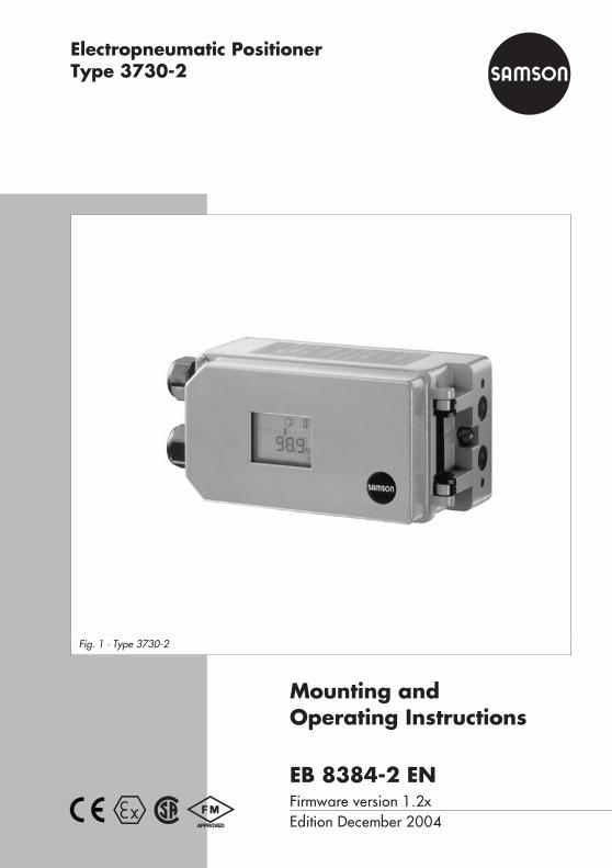
Fig. 4 · Direct attachment – Signal pressure connection for Type 3277 Actuator with 240, 350 and 700 cm2
2
10 1415
1 2 3 11
SUPPLY
13
16
B
1.11.2
1212.1
12
12.1
12.2
A
1216 12.2SUPPLY
Cut-out ofcover plate (10)
Actuator stemretracts extends
Stem retracts
Stem extends
Marking
Connection block (old)with switch plate (13)
Lever M
1 Lever1.1 Nut1.2 Disk spring2 Follower pin3 Follower clamp10 Cover plate11 Cover12 Connection block
12.1 Screw12.2 Stopper or connection for
external piping13 Switch plate14 Gasket15 Formed seal16 Gasket
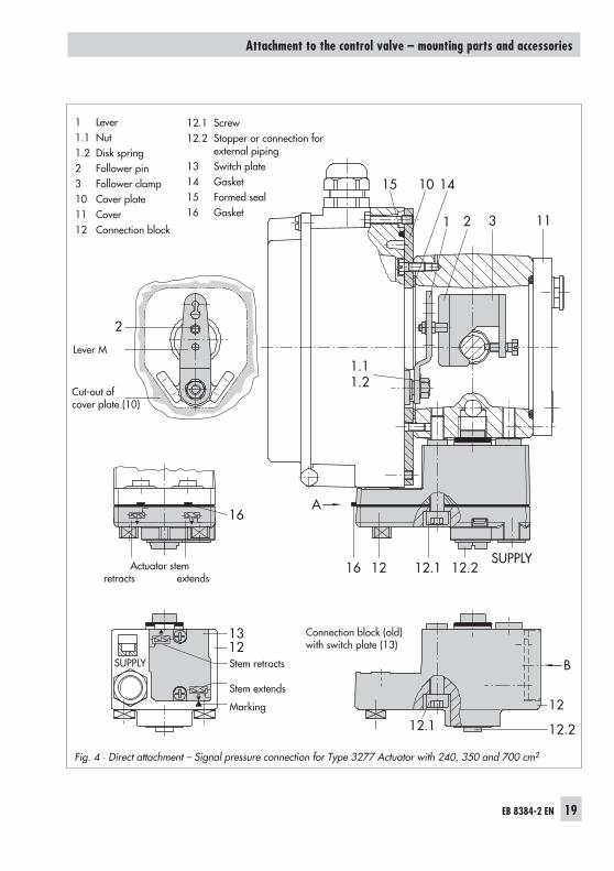
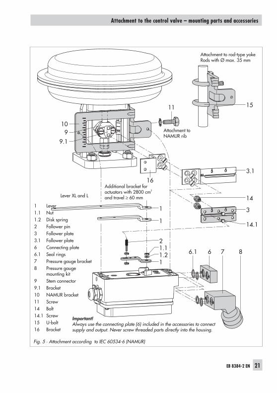
2.2 Attachment according toIEC 60534-6
The positioner is attached to the controlvalve with a NAMUR bracket (10).
Refer to Table 3 on page 14 for the requiredmounting parts as well as the accessorieswith their order numbers.Note the travel table on page 13!
1. Screw the two bolts (14) to the bracket(9.1) of the stem connector (9), place thefollower plate (3) on top and use thescrews (14.1) to tighten.
Actuator size 2800 cm2:For a travel of 60 mm or smaller, screwthe longer follower plate (3.1) directly tothe stem connector (9). For a travel ex-ceeding 60 mm, mount the bracket (16)first and then the follower plate (3) to thebracket together with the bolts (14) andscrews (14.1).
2. Mount NAMUR bracket (10) to the con-trol valve as follows:For attachment to the NAMUR rib, usean M8 screw (11) and toothed lockwasher directly in the yoke bore.For attachment to valves with rod-typeyokes, use two U-bolts (15) around theyoke.Align the NAMUR bracket (10) accord-ing to the embossed scale so that the slotof the follower plate (3) is centrallyaligned with the NAMUR bracket at midvalve travel.
3. Mount connecting plate (6) or pressuregauge bracket (7) with pressure gauges(8) on the positioner, making sure bothseal rings (6.1) are seated properly.
4. Select required lever size (1) M, L or XLand pin position according to the actua-tor size and valve travels listed in the ta-ble below.Should you require a pin position otherthan position 35 with the standard in-stalled lever M, or require a lever size Lor XL, proceed as follows:
5. Screw the follower pin (2) in the as-signed lever bore (pin position) as listedin the table. Only use the longer followerpin (2) included in the mounting kit.
6. Place lever (1) on the positioner shaftand screw tight using the disk spring(1.2) and nut (1.1).
Note!If you have mounted a new lever (1), youmust move it once all the way as far as itwill go in both directions.
7. Place positioner on the NAMUR bracketin such a manner that the follower pin(2) rests in the slot of the follower plate(3, 3.1). Adjust the lever (1) correspond-ingly.Screw the positioner to the NAMURbracket using both its fixing screws.
20 EB 8384-2 EN
Attachment to the control valve – mounting parts and accessories
EB 8384-2 EN 21
Attachment to the control valve – mounting parts and accessories
Fig. 5 · Attachment according to IEC 60534-6 (NAMUR)
10
11
6.1 6 7 8
1
1 14.1
3
3.116
15
14
11.21.12
9.19 Attachment to
NAMUR rib
Additional bracket foractuators with 2800 cm2
and travel ≥ 60 mm
Attachment to rod-type yokeRods with Ø max. 35 mm
Lever XL and L
1 Lever1.1 Nut1.2 Disk spring2 Follower pin3 Follower plate3.1 Follower plate6 Connecting plate6.1 Seal rings7 Pressure gauge bracket8 Pressure gauge
mounting kit9 Stem connector9.1 Bracket10 NAMUR bracket11 Screw14 Bolt14.1 Screw15 U-bolt16 Bracket
Important!Always use the connecting plate (6) included in the accessories to connectsupply and output. Never screw threaded parts directly into the housing.
2.3 Attachment to Type 3510Micro-flow Valve
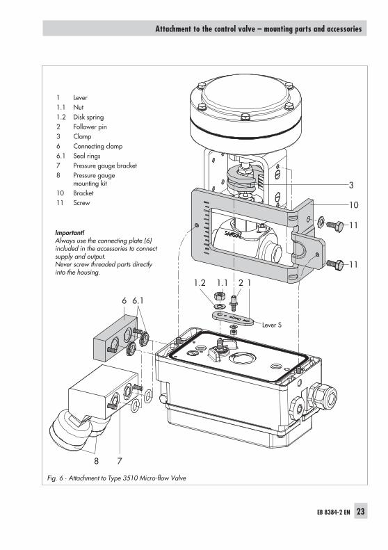
The positioner is attached to the valve yokeusing a bracket.
Refer to Table 3 on page 14 for the requiredmounting parts as well as the accessorieswith their order numbers.Note the travel table on page 13!
1. Place clamp (3) on the valve stem con-nector, align at a right angle and screwtight.
2. Screw bracket (10) to the valve yoke us-ing two screws (11).
3. Mount connecting plate (6) or pressuregauge bracket (7) with pressure gaugesto the positioner, making sure both sealrings (6.1) are seated properly.
4. Unscrew the standard installed lever M(1) including follower pin (2) from thepositioner shaft.
5. Take lever S (1) and screw follower pin(2) in the bore for pin position 17.
6. Place lever S on the positioner shaft andscrew tight using the disk spring (1.2)and nut (1.1).Move lever once all the way as far as itwill go in both directions.
7. Place positioner on the bracket (10) insuch a manner that the follower pinslides into the groove of the clamp (3).Adjust the lever (1) correspondingly.Screw the positioner to the bracket (10)using both its hexagon screws.
22 EB 8384-2 EN
Attachment to the control valve – mounting parts and accessories
EB 8384-2 EN 23
Attachment to the control valve – mounting parts and accessories
Fig. 6 · Attachment to Type 3510 Micro-flow Valve
3
10
11
11
6
121.2 1.1
78
6.1
1 Lever1.1 Nut1.2 Disk spring2 Follower pin3 Clamp6 Connecting clamp6.1 Seal rings7 Pressure gauge bracket8 Pressure gauge
mounting kit10 Bracket11 Screw
Important!Always use the connecting plate (6)included in the accessories to connectsupply and output.Never screw threaded parts directlyinto the housing.
Lever S
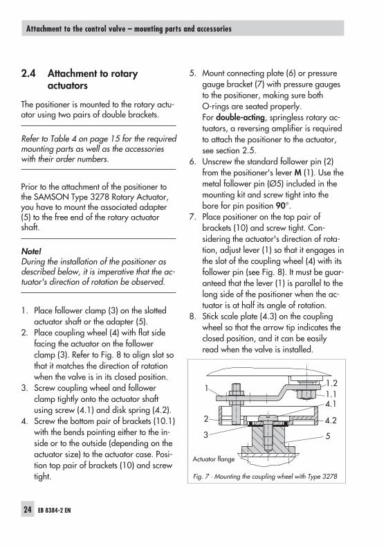
2.4 Attachment to rotaryactuators
The positioner is mounted to the rotary actu-ator using two pairs of double brackets.
Refer to Table 4 on page 15 for the requiredmounting parts as well as the accessorieswith their order numbers.
Prior to the attachment of the positioner tothe SAMSON Type 3278 Rotary Actuator,you have to mount the associated adapter(5) to the free end of the rotary actuatorshaft.
Note!During the installation of the positioner asdescribed below, it is imperative that the ac-tuator's direction of rotation be observed.
1. Place follower clamp (3) on the slottedactuator shaft or the adapter (5).
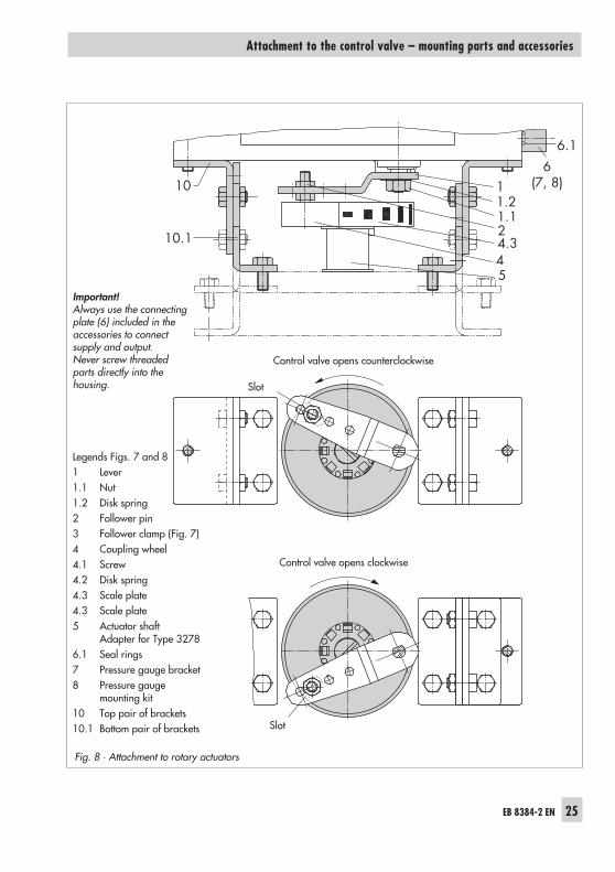
2. Place coupling wheel (4) with flat sidefacing the actuator on the followerclamp (3). Refer to Fig. 8 to align slot sothat it matches the direction of rotationwhen the valve is in its closed position.
3. Screw coupling wheel and followerclamp tightly onto the actuator shaftusing screw (4.1) and disk spring (4.2).
4. Screw the bottom pair of brackets (10.1)with the bends pointing either to the in-side or to the outside (depending on theactuator size) to the actuator case. Posi-tion top pair of brackets (10) and screwtight.
5. Mount connecting plate (6) or pressuregauge bracket (7) with pressure gaugesto the positioner, making sure bothO-rings are seated properly.For double-acting, springless rotary ac-tuators, a reversing amplifier is requiredto attach the positioner to the actuator,see section 2.5.
6. Unscrew the standard follower pin (2)from the positioner's lever M (1). Use themetal follower pin (Ø5) included in themounting kit and screw tight into thebore for pin position 90°.
7. Place positioner on the top pair ofbrackets (10) and screw tight. Con-sidering the actuator's direction of rota-tion, adjust lever (1) so that it engages inthe slot of the coupling wheel (4) with itsfollower pin (see Fig. 8). It must be guar-anteed that the lever (1) is parallel to thelong side of the positioner when the ac-tuator is at half its angle of rotation.
8. Stick scale plate (4.3) on the couplingwheel so that the arrow tip indicates theclosed position, and it can be easilyread when the valve is installed.
24 EB 8384-2 EN
Attachment to the control valve – mounting parts and accessories
Fig. 7 · Mounting the coupling wheel with Type 3278
1.21.1
1
2
4.1
4.2
53
Actuator flange
EB 8384-2 EN 25
Attachment to the control valve – mounting parts and accessories
Fig. 8 · Attachment to rotary actuators
Slot
10
10.1
6(7, 8)
1.124.3
5
6.1
4
1.21
Control valve opens clockwise
Control valve opens counterclockwise
Slot
Important!Always use the connectingplate (6) included in theaccessories to connectsupply and output.Never screw threadedparts directly into thehousing.
Legends Figs. 7 and 81 Lever1.1 Nut1.2 Disk spring2 Follower pin3 Follower clamp (Fig. 7)4 Coupling wheel4.1 Screw4.2 Disk spring4.3 Scale plate4.3 Scale plate5 Actuator shaft
Adapter for Type 32786.1 Seal rings7 Pressure gauge bracket8 Pressure gauge
mounting kit10 Top pair of brackets10.1 Bottom pair of brackets
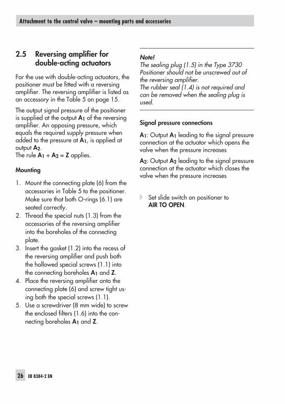
2.5 Reversing amplifier fordouble-acting actuators
For the use with double-acting actuators, thepositioner must be fitted with a reversingamplifier. The reversing amplifier is listed asan accessory in the Table 5 on page 15.
The output signal pressure of the positioneris supplied at the output A1 of the reversingamplifier. An opposing pressure, whichequals the required supply pressure whenadded to the pressure at A1, is applied atoutput A2.The rule A1 + A2 = Z applies.
Mounting
1. Mount the connecting plate (6) from theaccessories in Table 5 to the positioner.Make sure that both O-rings (6.1) areseated correctly.
2. Thread the special nuts (1.3) from theaccessories of the reversing amplifierinto the boreholes of the connectingplate.
3. Insert the gasket (1.2) into the recess ofthe reversing amplifier and push boththe hollowed special screws (1.1) intothe connecting boreholes A1 and Z.
4. Place the reversing amplifier onto theconnecting plate (6) and screw tight us-ing both the special screws (1.1).
5. Use a screwdriver (8 mm wide) to screwthe enclosed filters (1.6) into the con-necting boreholes A1 and Z.
Note!The sealing plug (1.5) in the Type 3730Positioner should not be unscrewed out ofthe reversing amplifier.The rubber seal (1.4) is not required andcan be removed when the sealing plug isused.
Signal pressure connections
A1: Output A1 leading to the signal pressureconnection at the actuator which opens thevalve when the pressure increases
A2: Output A2 leading to the signal pressureconnection at the actuator which closes thevalve when the pressure increases
Set slide switch on positioner toAIR TO OPEN.
26 EB 8384-2 EN
Attachment to the control valve – mounting parts and accessories
EB 8384-2 EN 27
Attachment to the control valve – mounting parts and accessories
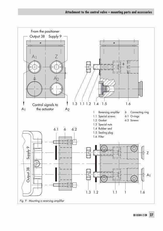
Fig. 9 · Mounting a reversing amplifier
A1
1.5 1.6
1.3
6.266.1
1.2 1.1 1 1.6
Z
A2
1.4A1 A2
Z
A1
Output 38 Supply 9
Out
put 3
8Su
pply
9
1.3 1.21.1
1 Reversing amplifer1.1 Special screws1.2 Gasket1.3 Special nuts1.4 Rubber seal1.5 Sealing plug1.6 Filter
6 Connecting ring6.1 O-rings6.2 Screws
From the positioner
Control signals tothe actuator
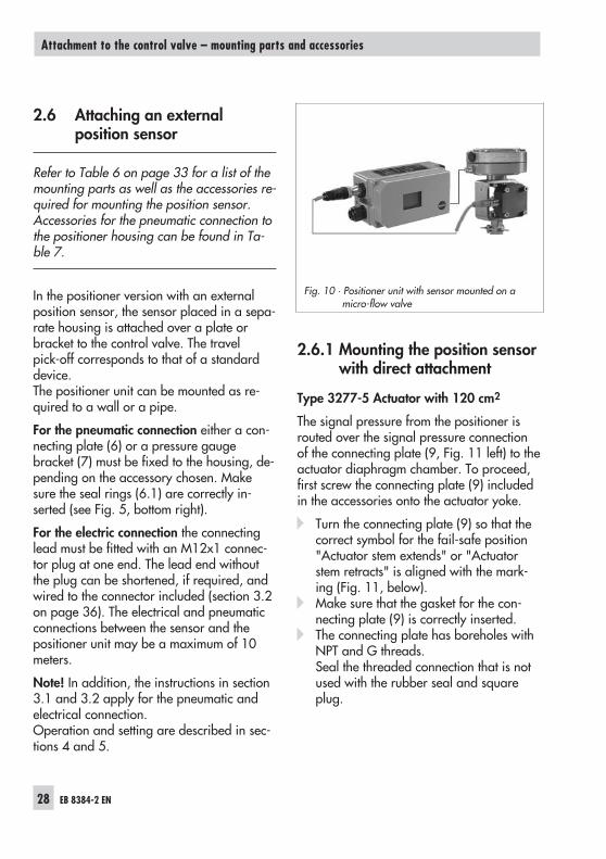
2.6 Attaching an externalposition sensor
Refer to Table 6 on page 33 for a list of themounting parts as well as the accessories re-quired for mounting the position sensor.Accessories for the pneumatic connection tothe positioner housing can be found in Ta-ble 7.
In the positioner version with an externalposition sensor, the sensor placed in a sepa-rate housing is attached over a plate orbracket to the control valve. The travelpick-off corresponds to that of a standarddevice.The positioner unit can be mounted as re-quired to a wall or a pipe.
For the pneumatic connection either a con-necting plate (6) or a pressure gaugebracket (7) must be fixed to the housing, de-pending on the accessory chosen. Makesure the seal rings (6.1) are correctly in-serted (see Fig. 5, bottom right).
For the electric connection the connectinglead must be fitted with an M12x1 connec-tor plug at one end. The lead end withoutthe plug can be shortened, if required, andwired to the connector included (section 3.2on page 36). The electrical and pneumaticconnections between the sensor and thepositioner unit may be a maximum of 10meters.
Note! In addition, the instructions in section3.1 and 3.2 apply for the pneumatic andelectrical connection.Operation and setting are described in sec-tions 4 and 5.
2.6.1 Mounting the position sensorwith direct attachment
Type 3277-5 Actuator with 120 cm2
The signal pressure from the positioner isrouted over the signal pressure connectionof the connecting plate (9, Fig. 11 left) to theactuator diaphragm chamber. To proceed,first screw the connecting plate (9) includedin the accessories onto the actuator yoke.
Turn the connecting plate (9) so that thecorrect symbol for the fail-safe position"Actuator stem extends" or "Actuatorstem retracts" is aligned with the mark-ing (Fig. 11, below).
Make sure that the gasket for the con-necting plate (9) is correctly inserted.
The connecting plate has boreholes withNPT and G threads.Seal the threaded connection that is notused with the rubber seal and squareplug.
28 EB 8384-2 EN
Attachment to the control valve – mounting parts and accessories
Fig. 10 · Positioner unit with sensor mounted on amicro-flow valve
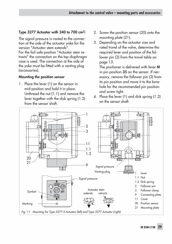
Type 3277 Actuator with 240 to 700 cm2:
The signal pressure is routed to the connec-tion at the side of the actuator yoke for theversion "Actuator stem extends".For the fail-safe position "Actuator stem re-tracts" the connection on the top diaphragmcase is used. The connection at the side ofthe yoke must be fitted with a venting plug(accessories).
Mounting the position sensor
1. Place the lever (1) on the sensor inmid-position and hold it in place.Unthread the nut (1.1) and remove thelever together with the disk spring (1.2)from the sensor shaft.
2. Screw the position sensor (20) onto themounting plate (21).
3. Depending on the actuator size andrated travel of the valve, determine therequired lever and position of the fol-lower pin (2) from the travel table onpage 13.The positioner is delivered with lever Min pin position 35 on the sensor. If nec-essary, remove the follower pin (2) fromits pin position and move it to the bore-hole for the recommended pin positionand screw tight.
4. Place the lever (1) and disk spring (1.2)on the sensor shaft.
EB 8384-2 EN 29
Attachment to the control valve – mounting parts and accessories
Fig. 11 · Mounting for Type 3277-5 Actuator (left) and Type 3277 Actuator (right)
2021
9
111.11.2
32
1
Signal pressure
Venting plug
Actuator stemextends retractsSymbol
Marking
Signal pressure
1 Lever1.1 Nut1.2 Disk spring2 Follower pin3 Follower clamp9 Connecting plate11 Cover20 Position sensor21 Mounting plate
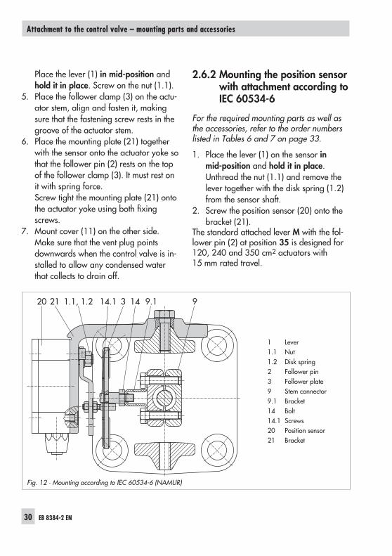
Place the lever (1) in mid-position andhold it in place. Screw on the nut (1.1).
5. Place the follower clamp (3) on the actu-ator stem, align and fasten it, makingsure that the fastening screw rests in thegroove of the actuator stem.
6. Place the mounting plate (21) togetherwith the sensor onto the actuator yoke sothat the follower pin (2) rests on the topof the follower clamp (3). It must rest onit with spring force.Screw tight the mounting plate (21) ontothe actuator yoke using both fixingscrews.
7. Mount cover (11) on the other side.Make sure that the vent plug pointsdownwards when the control valve is in-stalled to allow any condensed waterthat collects to drain off.
2.6.2 Mounting the position sensorwith attachment according toIEC 60534-6
For the required mounting parts as well asthe accessories, refer to the order numberslisted in Tables 6 and 7 on page 33.
1. Place the lever (1) on the sensor inmid-position and hold it in place.Unthread the nut (1.1) and remove thelever together with the disk spring (1.2)from the sensor shaft.
2. Screw the position sensor (20) onto thebracket (21).
The standard attached lever M with the fol-lower pin (2) at position 35 is designed for120, 240 and 350 cm2 actuators with15 mm rated travel.
30 EB 8384-2 EN
Attachment to the control valve – mounting parts and accessories
Fig. 12 · Mounting according to IEC 60534-6 (NAMUR)
20 21 1.1, 1.2 14.1 3 14 99.1
1 Lever1.1 Nut1.2 Disk spring2 Follower pin3 Follower plate9 Stem connector9.1 Bracket14 Bolt14.1 Screws20 Position sensor21 Bracket
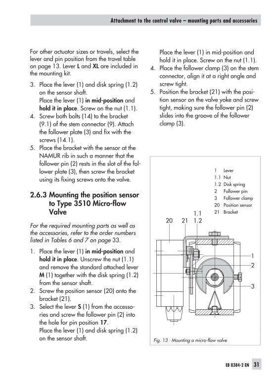
For other actuator sizes or travels, select thelever and pin position from the travel tableon page 13. Lever L and XL are included inthe mounting kit.
3. Place the lever (1) and disk spring (1.2)on the sensor shaft.Place the lever (1) in mid-position andhold it in place. Screw on the nut (1.1).
4. Screw both bolts (14) to the bracket(9.1) of the stem connector (9). Attachthe follower plate (3) and fix with thescrews (14.1).
5. Place the bracket with the sensor at theNAMUR rib in such a manner that thefollower pin (2) rests in the slot of the fol-lower plate (3), then screw the bracketusing its fixing screws onto the valve.
2.6.3 Mounting the position sensorto Type 3510 Micro-flowValve
For the required mounting parts as well asthe accessories, refer to the order numberslisted in Tables 6 and 7 on page 33.
1. Place the lever (1) in mid-position andhold it in place. Unscrew the nut (1.1)and remove the standard attached leverM (1) together with the disk spring (1.2)from the sensor shaft.
2. Screw the position sensor (20) onto thebracket (21).
3. Select the lever S (1) from the accesso-ries and screw the follower pin (2) intothe hole for pin position 17.Place the lever (1) and disk spring (1.2)on the sensor shaft.
Place the lever (1) in mid-position andhold it in place. Screw on the nut (1.1).
4. Place the follower clamp (3) on the stemconnector, align it at a right angle andscrew tight.
5. Position the bracket (21) with the posi-tion sensor on the valve yoke and screwtight, making sure the follower pin (2)slides into the groove of the followerclamp (3).
EB 8384-2 EN 31
Attachment to the control valve – mounting parts and accessories
Fig. 13 · Mounting a micro-flow valve
20 211.11.2
1
3
2
1 Lever1.1 Nut1.2 Disk spring2 Follower pin3 Follower clamp20 Position sensor21 Bracket
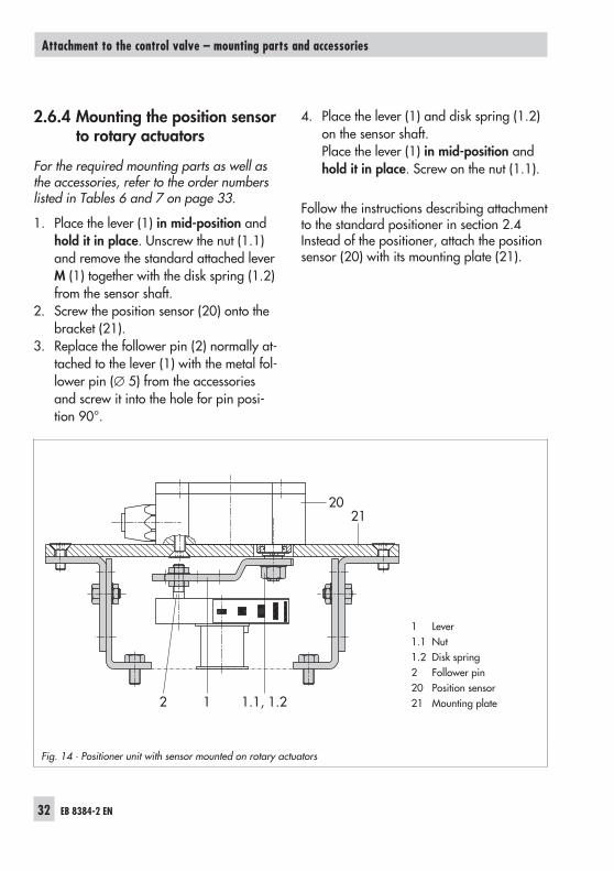
2.6.4 Mounting the position sensorto rotary actuators
For the required mounting parts as well asthe accessories, refer to the order numberslisted in Tables 6 and 7 on page 33.
1. Place the lever (1) in mid-position andhold it in place. Unscrew the nut (1.1)and remove the standard attached leverM (1) together with the disk spring (1.2)from the sensor shaft.
2. Screw the position sensor (20) onto thebracket (21).
3. Replace the follower pin (2) normally at-tached to the lever (1) with the metal fol-lower pin (∅ 5) from the accessoriesand screw it into the hole for pin posi-tion 90°.
4. Place the lever (1) and disk spring (1.2)on the sensor shaft.Place the lever (1) in mid-position andhold it in place. Screw on the nut (1.1).
Follow the instructions describing attachmentto the standard positioner in section 2.4Instead of the positioner, attach the positionsensor (20) with its mounting plate (21).
32 EB 8384-2 EN
Attachment to the control valve – mounting parts and accessories
Fig. 14 · Positioner unit with sensor mounted on rotary actuators
2021
2 1 1.1, 1.2
1 Lever1.1 Nut1.2 Disk spring2 Follower pin20 Position sensor21 Mounting plate
EB 8384-2 EN 33
Attachment to the control valve – mounting parts and accessories
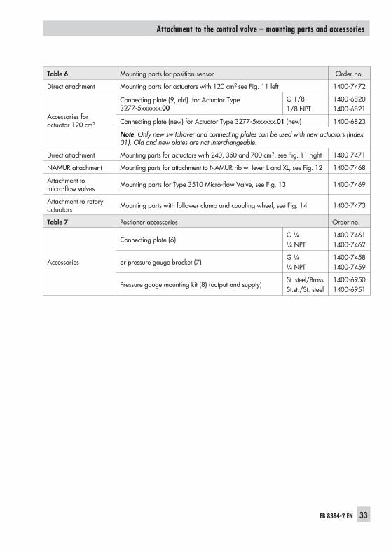
Table 6 Mounting parts for position sensor Order no.
Direct attachment Mounting parts for actuators with 120 cm2 see Fig. 11 left 1400-7472
Accessories foractuator 120 cm2
Connecting plate (9, old) for Actuator Type3277-5xxxxxx.00
G 1/81/8 NPT
1400-68201400-6821
Connecting plate (new) for Actuator Type 3277-5xxxxxx.01 (new) 1400-6823
Note: Only new switchover and connecting plates can be used with new actuators (Index01). Old and new plates are not interchangeable.
Direct attachment Mounting parts for actuators with 240, 350 and 700 cm2, see Fig. 11 right 1400-7471
NAMUR attachment Mounting parts for attachment to NAMUR rib w. lever L and XL, see Fig. 12 1400-7468
Attachment tomicro-flow valves Mounting parts for Type 3510 Micro-flow Valve, see Fig. 13 1400-7469
Attachment to rotaryactuators Mounting parts with follower clamp and coupling wheel, see Fig. 14 1400-7473
Table 7 Postioner accessories Order no.
Accessories
Connecting plate (6)G ¼¼ NPT
1400-74611400-7462
or pressure gauge bracket (7)G ¼¼ NPT
1400-74581400-7459
Pressure gauge mounting kit (8) (output and supply)St. steel/BrassSt.st./St. steel
1400-69501400-6951
3 Connections
3.1 Pneumatic connections
Caution!The threads in the positioner housing are notdesigned for direct air connection!
The screw glands must be screwed into theconnecting plate, the pressure gauge mount-ing block or the connection block from theaccessories. The air connections are option-ally designed as a bore with ¼ NPT or G ¼thread.The customary fittings for metal and copperpipes or plastic hoses can be used.
Note!The supply air must be dry and free from oiland dust. The maintenance instructions forupstream pressure reducing stations must beobserved.Blow through all air tubes and hoses thor-oughly prior to connecting them.
If the positioner is attached directly to theType 3277 Actuator, the connection of thepositioner's output pressure to the actuatoris fixed. For attachment according toIEC 60534-6 (NAMUR), the signal pressurecan be routed to either the top or bottom di-aphragm chamber of the actuator, depend-ing on the actuator's fail-safe action "Actua-tor stem extends" or "Actuator stem re-tracts".For rotary actuators, the manufacturer'sspecifications for connection apply.
3.1.1 Signal pressure gauges
To monitor the supply air (Supply) and sig-nal pressure (Output), we recommend thatpressure gauges be attached (see accesso-ries in Tables 1 to 5).
3.1.2 Supply pressure
The required supply air pressure dependson the bench range and the actuator's oper-ating direction (fail-safe action).The bench range is registered on the name-plate either as spring range or signal pres-sure range depending on the actuator. dieThe direction of action is marked FA or FE,or by a symbol.
Actuator stem extends FA (Air to openATO)
Fail-safe position "Valve Closed"(for globe and angle valves):
Required supply pressure = Upper benchrange value + 0.2 bar, minimum 1.4 bar.
Actuator stem retracts FE (Air to close ATC)
Fail-safe position "Valve Open"(for globe and angle valves):For tight-closing valves, the maximum signalpressure pstmax is roughly estimated as fol-lows:
pstmax = F + d pA
2
4⋅ ⋅
⋅π ∆
34 EB 8384-2 EN
Connections
d = Seat diameter [cm]∆p = Differential pressure across the valve
[bar]A = Actuator diaphragm area [cm2]F = Upper bench range of the actuator
[bar]
If there are no specifications, calculate asfollows:
Required supply pressure =Upper bench range value + 1 bar
Note!The signal pressure at the output (Out-put 38) of the positioner can be limited to1.4, 2.4 or 3.7 bar over Code 16 or thepressure limit can be deactivated (MAX).
EB 8384-2 EN 35
Connections
3.2 Electrical connections
For electrical installation, you are re-quired to observe the relevant elec-trotechnical regulations and the acci-dent prevention regulations that ap-ply in the country of use. In Germa-ny, these are the VDE regulationsand the accident prevention regula-tions of the employers' liability insu-rance association.The following standards apply for in-stallation in hazardous areas:EN 60079-14: 2003 (VDE 0165Part 1) "Electrical apparatus for ex-plosive gas atmospheres" andEN 50281-1-2: 1999 (VDE 0165Part 2) "Electrical apparatus for usein the presence of combustibledust".For the interconnection of intrinsical-ly safe electrical equipment, the per-missible maximum values specifiedin the EC type examination certifica-te apply (Ui or U0; Ii or I0; Pi or P0; Cior C0, and Li or L0).For EEx nA equipment (non-sparkingapparatus), the standard EN 50021:1999 specifies that connecting, inter-rupting, or switching circuits whileenergized is only allowed during in-stallation, maintenance or repairwork.For EEx nL equipment (energy-limit-ed apparatus), the standardEN 50021: 1999 allows this type ofequipment to be switched under nor-mal operating conditions.
Caution! The terminal assignment specifiedin the certificate must be adhered to. Re-versing the assignment of the electrical ter-minals may cause the explosion protectionto become ineffective!Do not tamper with enameled screws insideor on the housing.Note on the selection of cables and wires:To install intrinsically safe circuits, observesection 12 of the standard EN 60079-14:2003 (VDE 0165 Part 1). To run multi-corecables or lines with more than one intrinsi-cally safe circuit, section 12.2.2.7 of thisstandard applies.An additional cable gland can be installedwhen connecting the device over two sepa-rate cables. Cable entries left unused mustbe sealed with blanking plugs. Devices usedat ambient temperatures down to –40 °Cmust have metal cable entries.
The wires for the reference variable must beconnected to the terminals 11 and 12 lo-cated in the housing. Only use a currentsource!
Caution! The erroneous connection of a volt-age source of just around 7 V (or around2 V when connected to the wrong pole) candamage the positioner.
In general, it is not necessary to connect thepositioner to a bonding conductor. Shouldthis be required, however, this conductorcan be connected inside the device.Depending on the version, the positioner isequipped with inductive limit switchesand/or a solenoid valve.
36 EB 8384-2 EN
Connections
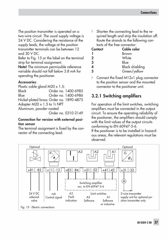
The position transmitter is operated on atwo-wire circuit. The usual supply voltage is24 V DC. Considering the resistance of thesupply leads, the voltage at the positiontransmitter terminals can be between 12and 30 V DC.Refer to Fig. 15 or the label on the terminalstrip for terminal assignment.Note! The minimum permissible referencevariable should not fall below 3.8 mA foroperating the positioner.
Accessories:Plastic cable gland M20 x 1.5:Black Order no. 1400-6985Blue Order no. 1400-6986Nickel-plated brass Order no. 1890-4875Adapter M20 x 1.5 to ½ NPTAluminum, powder-coated
Order no. 0310-2149
Connection for version with external posi-tion sensorThe terminal assignment is fixed by the con-nector of the connecting lead.
Shorten the connecting lead to the re-quired length and strip the insulation off.Route the strands to the following con-tacts of the free connector:
Contact Cable color1 Brown2 White3 Blue4 Black shielding5 Green/yellow
Connect the fixed M12x1 plug connectorto the position sensor and the mountedconnector to the positioner unit.
3.2.1 Switching amplifiers
For operation of the limit switches, switchingamplifiers must be connected in the outputcircuit. To ensure the operating reliability ofthe positioner, the amplifiers should complywith the limit values of the output circuitsconforming to EN 60947-5-6.If the positioner is to be installed in hazard-ous areas, the relevant regulations must beobserved.
EB 8384-2 EN 37
Connections
Fig. 15 · Electric connections
G
+81 -82 +11 -12 +83 -84 +51 -52
A2A3 A1
+41 -42 +31 -32
ASwitching amplifieracc. to EN 60947-5-6
24 V DCsolenoid
valve
mAControl signal
A3Fault
indication
Limit switchesA2 A1
Software Softwareor inductive
2-wire transmittersupply unit for optional po-sition transmitter only
Optional Optional
4 Operation
Note!A summary about operating and start upcan be found in section 7 on page 57. Aleaflet including the same summary is alsoenclosed with the positioner.
4.1 Operator controls anddisplay
Rotary pushbutton
The positioner is mainly operated with therotary pushbutton.
Turn the button to select and set codes,parameter and values. Press it to confirmthem.
Slide switch AIR TO OPEN or AIR TOCLOSE
This switch is used to adapt the positioner tothe operating direction of the actuator.
For actuator where the supply pressureopens the valve, fail-safe position: "springsclose valve": switch position AIR TO OPEN.
For actuator where the supply pressurecloses the valve, fail-safe position: "springsopen valve": switch position AIR TO CLOSE.
For positioners with an attached reversingamplifier for double-acting rotary actuators(section 2.5): switch position AIR TO OPEN.
The switch position is prompted prior to aninitialization. After an initialization has beencompleted, changing the switch positiondoes not have any effect on the operation ofthe positioner.
Volume restriction Q
The volume restriction is used to adapt theair delivery to the actuator size. Two fixedsettings are possible depending on how theair is routed at the actuator:
For actuators smaller than 240 cm2 witha loading pressure connection at the side(Type 3271-5), set restriction to MINSIDE.
For a connection at the back (Type3277-5), set restriction to MIN BACK.
For actuators 240 cm2 and larger, set toMAX SIDE for a side connection and toMAX BACK for a connection at the back.
Displays
The LC display indicates symbols that areassigned to parameters, codes and func-tions.The bar graph in the operating modes Man-ual and Automatic indicates the sys-tem deviation that depends on the sign(+/−) and the value. One bar graph ele-ment appears per 1 % system deviation.
If the device has not yet been initialized (seesection 4.3.1), the lever position in degreesin relation to the longitudinal axis is indi-cated instead of the system deviation. Onebar graph element corresponds to approxi-mately a 5° angle of rotation.
If the fifth element blinks (value displayed> 30°), the permissible angle of rotation hasbeen exceeded. Lever and pin position mustbe checked.
38 EB 8384-2 EN
Operation
EB 8384-2 EN 39
Operation
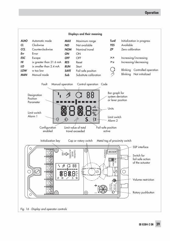
Fig. 16 · Display and operator controls
AUtO Automatic modeCL ClockwiseCCL CounterclockwiseErr ErrorESC EscapeHI ix greater than 21.6 mALO ix smaller than 2.4 mALOW w too lowMAN Manual mode
MAX Maximum rangeNO Not availableNOM Nominal travelON ONOFF OFFRES ResetRUN StartSAFE Fail-safe positionSub Substitute calibration
TunE Initialization in progressYES AvailableZP Zero calibration
Increasing/increasing Increasing/decreasing
Blinking Controlled operationBlinking Not initialized
Displays and their meaning
AIR TOO
PEN
CLO
SE
INIT
CA
UTIO
NVA
LVEA
CTU
ATES
MIN
SIDE
MA
X BAC
K
MIN
BAC
KM
AX SID
E Q
+81
-82+
11-12
+83
-84+
51-52
+41
-42+
31-32
%S
mm
%S
mm
SERIAL
INTERFA
CE
Fault Manual operation Control operation Code
Configurationenabled
Limit value of totaltravel exceeded
Fail-safe positionactive
Bar graph forsystem deviationor lever position
Units
Limit switchAlarm 2
DesignationPositionParameter
Limit switchAlarm 1
Initialization key Cap or rotary switch Metal tag of proximity switch
SSP interface
Switch forfail-safe actionof the actuator
Volume restriction
Rotary pushbutton
4.2 Enabling and selectingparameters
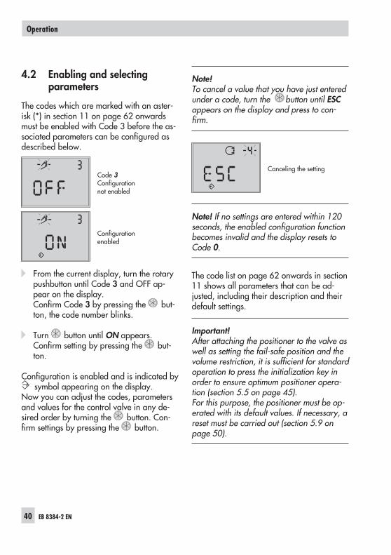
The codes which are marked with an aster-isk (*) in section 11 on page 62 onwardsmust be enabled with Code 3 before the as-sociated parameters can be configured asdescribed below.
Code 3Configurationnot enabled
Configurationenabled
From the current display, turn the rotarypushbutton until Code 3 and OFF ap-pear on the display.Confirm Code 3 by pressing the but-ton, the code number blinks.
Turn button until ON appears.Confirm setting by pressing the but-ton.
Configuration is enabled and is indicated bysymbol appearing on the display.
Now you can adjust the codes, parametersand values for the control valve in any de-sired order by turning the button. Con-firm settings by pressing the button.
Note!To cancel a value that you have just enteredunder a code, turn the button until ESCappears on the display and press to con-firm.
Canceling the setting
Note! If no settings are entered within 120seconds, the enabled configuration functionbecomes invalid and the display resets toCode 0.
The code list on page 62 onwards in section11 shows all parameters that can be ad-justed, including their description and theirdefault settings.
Important!After attaching the positioner to the valve aswell as setting the fail-safe position and thevolume restriction, it is sufficient for standardoperation to press the initialization key inorder to ensure optimum positioner opera-tion (section 5.5 on page 45).For this purpose, the positioner must be op-erated with its default values. If necessary, areset must be carried out (section 5.9 onpage 50).
40 EB 8384-2 EN
Operation
4.3 Operating modes
4.3.1 Automatic and manualoperating modes
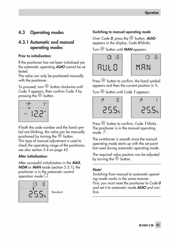
Prior to initialization:
If the positioner has not been initialized yet,the automatic operating AUtO cannot be se-lected.The valve can only be positioned manuallywith the positioner.
To proceed, turn button clockwise untilCode 1 appears, then confirm Code 1 bypressing the button.
If both the code number and the hand sym-bol are blinking, the valve can be manuallypositioned by turning the button.This type of manual adjustment is used tocheck the operating range of the positioner,see also section 5.4 on page 43.
After initialization:
After successful initialization in the MAX,NOM or MAN mode (section 5.5.1), thepositioner is in the automatic controloperation mode .
Standard
Switching to manual operating mode
Over Code 0, press the button, AUtOappears in the display, Code 0 blinks.
Turn button until MAN appears.
Press button to confirm, the hand symbolappears and then the current position in %.
Turn button until Code 1 appears.
Press button to confirm, Code 1 blinks.The positioner is in the manual operatingmode .
The switchover is smooth since the manualoperating mode starts up with the set pointlast used during automatic operating mode.
The required valve position can be adjustedby turning the button.
Note!Switching from manual to automatic operat-ing mode works in the same manner.First, you must reset the positioner to Code 0and set it to automatic mode AUtO and con-firm.
EB 8384-2 EN 41
Operation
%
% %
4.3.2 SAFE – Fail-safe position
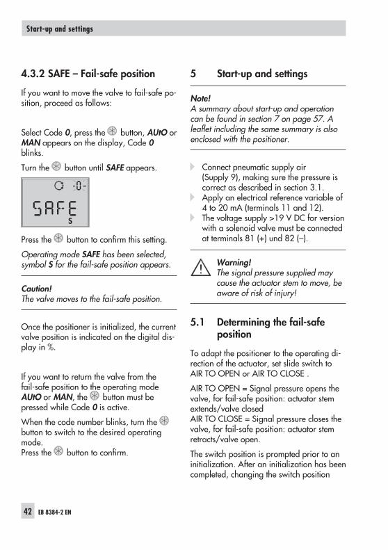
If you want to move the valve to fail-safe po-sition, proceed as follows:
Select Code 0, press the button, AUtO orMAN appears on the display, Code 0blinks.
Turn the button until SAFE appears.
Press the button to confirm this setting.
Operating mode SAFE has been selected,symbol S for the fail-safe position appears.
Caution!The valve moves to the fail-safe position.
Once the positioner is initialized, the currentvalve position is indicated on the digital dis-play in %.
If you want to return the valve from thefail-safe position to the operating modeAUtO or MAN, the button must bepressed while Code 0 is active.
When the code number blinks, turn thebutton to switch to the desired operatingmode.Press the button to confirm.
5 Start-up and settings
Note!A summary about start-up and operationcan be found in section 7 on page 57. Aleaflet including the same summary is alsoenclosed with the positioner.
Connect pneumatic supply air(Supply 9), making sure the pressure iscorrect as described in section 3.1.
Apply an electrical reference variable of4 to 20 mA (terminals 11 and 12).
The voltage supply >19 V DC for versionwith a solenoid valve must be connectedat terminals 81 (+) und 82 (–).
Warning!The signal pressure supplied maycause the actuator stem to move, beaware of risk of injury!
5.1 Determining the fail-safeposition
To adapt the positioner to the operating di-rection of the actuator, set slide switch toAIR TO OPEN or AIR TO CLOSE .
AIR TO OPEN = Signal pressure opens thevalve, for fail-safe position: actuator stemextends/valve closedAIR TO CLOSE = Signal pressure closes thevalve, for fail-safe position: actuator stemretracts/valve open.
The switch position is prompted prior to aninitialization. After an initialization has beencompleted, changing the switch position
42 EB 8384-2 EN
Start-up and settings
S
does not have any effect on the operation ofthe positioner.
5.2 Setting the volume restriction Q
For actuators smaller than 240 cm2 witha loading pressure connection at the side(Type 3271-5), set restriction to MINSIDE.
For a connection at the back(Type 3277-5), set restriction to MINBACK.
For actuators 240 cm2 and larger, set toMAX SIDE for a side connection and toMAX BACK for a connection at the back.
Note! The positioner must re-initialized if thevolume restriction setting is changed afterthe positioner has already been initialized.
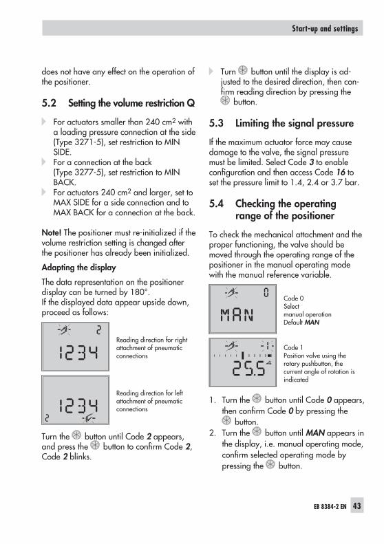
Adapting the display
The data representation on the positionerdisplay can be turned by 180°.If the displayed data appear upside down,proceed as follows:
Reading direction for rightattachment of pneumaticconnections
Reading direction for leftattachment of pneumaticconnections
Turn the button until Code 2 appears,and press the button to confirm Code 2,Code 2 blinks.
Turn button until the display is ad-justed to the desired direction, then con-firm reading direction by pressing the
button.
5.3 Limiting the signal pressure
If the maximum actuator force may causedamage to the valve, the signal pressuremust be limited. Select Code 3 to enableconfiguration and then access Code 16 toset the pressure limit to 1.4, 2.4 or 3.7 bar.
5.4 Checking the operatingrange of the positioner
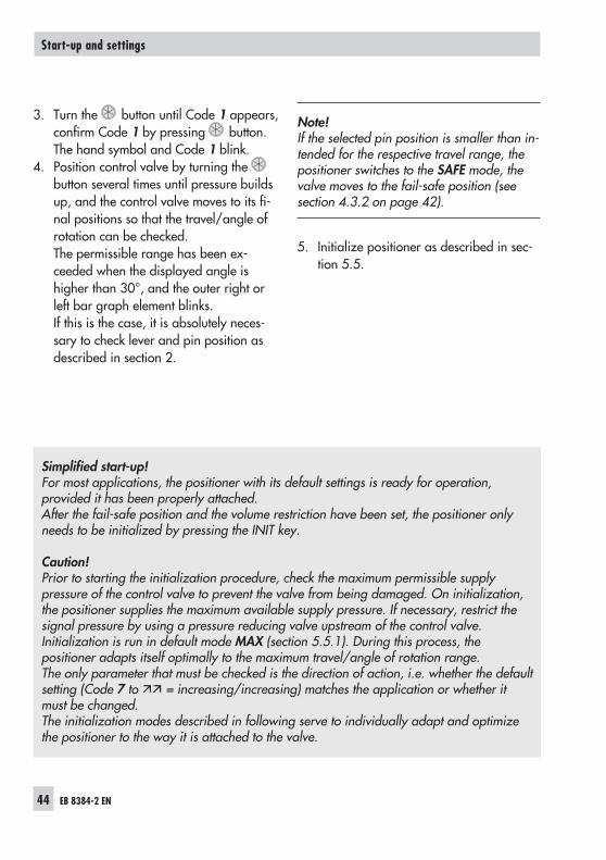
To check the mechanical attachment and theproper functioning, the valve should bemoved through the operating range of thepositioner in the manual operating modewith the manual reference variable.
Code 0Selectmanual operationDefault MAN
Code 1Position valve using therotary pushbutton, thecurrent angle of rotation isindicated
1. Turn the button until Code 0 appears,then confirm Code 0 by pressing the
button.2. Turn the button until MAN appears in
the display, i.e. manual operating mode,confirm selected operating mode bypressing the button.
EB 8384-2 EN 43
Start-up and settings
3. Turn the button until Code 1 appears,confirm Code 1 by pressing button.The hand symbol and Code 1 blink.
4. Position control valve by turning thebutton several times until pressure buildsup, and the control valve moves to its fi-nal positions so that the travel/angle ofrotation can be checked.The permissible range has been ex-ceeded when the displayed angle ishigher than 30°, and the outer right orleft bar graph element blinks.If this is the case, it is absolutely neces-sary to check lever and pin position asdescribed in section 2.
Note!If the selected pin position is smaller than in-tended for the respective travel range, thepositioner switches to the SAFE mode, thevalve moves to the fail-safe position (seesection 4.3.2 on page 42).
5. Initialize positioner as described in sec-tion 5.5.
44 EB 8384-2 EN
Start-up and settings
Simplified start-up!For most applications, the positioner with its default settings is ready for operation,provided it has been properly attached.After the fail-safe position and the volume restriction have been set, the positioner onlyneeds to be initialized by pressing the INIT key.
Caution!Prior to starting the initialization procedure, check the maximum permissible supplypressure of the control valve to prevent the valve from being damaged. On initialization,the positioner supplies the maximum available supply pressure. If necessary, restrict thesignal pressure by using a pressure reducing valve upstream of the control valve.Initialization is run in default mode MAX (section 5.5.1). During this process, thepositioner adapts itself optimally to the maximum travel/angle of rotation range.The only parameter that must be checked is the direction of action, i.e. whether the defaultsetting (Code 7 to = increasing/increasing) matches the application or whether itmust be changed.The initialization modes described in following serve to individually adapt and optimizethe positioner to the way it is attached to the valve.
5.5 Initialization
During initialization the positioner adapts it-self optimally to the friction conditions andthe signal pressure demand of the controlvalve.The type and extent of self-adaptation de-pends on the set initialization mode (seesection 5.5.1).MAX is the default setting for initializationbased on the maximum nominal range.
If configuration is enabled via Code 3, Code6 can be used to change to other initializa-tion modes.
If the positioner has been initialized once al-ready, it will automatically go to the operat-ing mode used last after the electrical refer-ence variable is applied, Code 0 appearson the display.On initializing the positioner for the firsttime, the hand symbol appears on thedisplay.
Note!Every time you re-initialize the positioner, itshould be reset to its basic setting includingthe default values. Refer to section 5.9 onpage 50.
The initialization process can be startedby pressing the INIT key with a suitabletool.
Note!The time required for the initialization pro-cedure depends on the running time of theactuator and can take a few minutes.
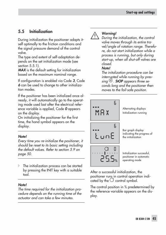
Warning!During the initialization, the controlvalve moves through its entire tra-vel/angle of rotation range. Therefo-re, do not start initialization while aprocess is running, but only duringstart-up, when all shut-off valves areclosed.Note!The initalization procedure can beinterrupted while running by pres-sing . StOP appears three se-conds long and the positioner thenmoves to the fail-safe position.
Alternating displaysInitialization running
Bar graph displayindicating the progress ofthe initialization
Initialization successful,positioner in automaticoperating mode
After a successful initialization, thepositioner runs in control operation indi-cated by the control symbol.
The control position in % predetermined bythe reference variable appears on the dis-play.
EB 8384-2 EN 45
Start-up and settings
%
A malfunctioning leads to the process beinginterrupted. The fault symbol appears onthe display. See section 5.7 on page 53.If the slide switch is set to AIR TO CLOSE,the positioner with firmware version 1.10 orhigher automatically switches to the direc-tion of action increasing/decreasing ()on successful completion of initialization.This results in the following assignment be-tween reference variable and valve position:
Fail-safe positi-on
Direction ofaction
ValveClosed at Open at
Actuator stemextends FA
AIR TO OPEN 4 mA 20 mA
Actuator stemretracts FE
AIR TO CLOSE 20 mA 4 mA
The tight-closing function is activated.Set Code 15 (final position w>) to 99 % forthree-way valves.Further settings relevant for the valve can beentered subsequently.
5.5.1 Initialization modes
After enabling configuration with Code 3and accessing Code 6, you can choose oneof the initialization modes MAX, NOM,MAN or SUb to start initialization.ZP, the zero calibration is described in sec-tion 5.8 on page 53.
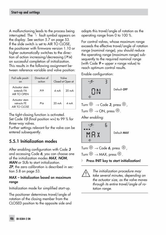
MAX – Initialization based on maximumrange
Initialization mode for simplified start-up.
The positioner determines travel/angle ofrotation of the closing member from theCLOSED position to the opposite side and
adopts this travel/angle of rotation as theoperating range from 0 to 100 %.
For control valves, whose maximum rangeexceeds the effective travel/angle of rotationrange (nominal range), you should reducethe operating range (maximum range) sub-sequently to the required nominal range(with Code 9 = upper x-range value) toreach optimum control results.
Enable configuration:
Default OFF
Turn → Code 3, press ,
Turn → ON, press .
After enabling:
Default MAX
Turn → Code 6, press ,
Turn → MAX, press .
Press INIT key to start initialization!
The initialization procedure maytake several minutes, depending onthe actuator size, as the valve movesthrough its entire travel/angle of ro-tation range.
46 EB 8384-2 EN
Start-up and settings
Note!For MAX initialization, the positioner cannotindicate nominal travel/angle of rotation inmm/°, Code 5 remains disabled.In addition, the lower (Code 8) and the up-per (Code 9) x-range value can only be dis-played and modified in %.During MAX initialization, an increased sys-tem deviation (undefined final position of theactuator) in the upper control range may oc-cur with some control valves due to thepneumatic actuator design.
If you want the display to indicate mm/°,proceed as follows after configuration hasbeen enabled:
Turn → Code 4, press ,
turn → Select pin position enteredduring installation, press .
If you now switch to Code 5, the nominalrange appears in mm/°.The lower and upper x-range values forCode 8 and 9 are displayed in mm/° andcan be adapted accordingly.
NOM – Initialization based on nominalrange
Initialization mode for globe valves, espe-cially for valves with maximum ranges thatare clearly greater than the required nomi-nal range.For this initialization mode, the followingparameters must be entered: pin position(Code 4), nominal travel/angle (Code 5)and, if required, the direction of action(Code 7).
The calibrated sensor enables the effectivevalve travel to be preset very accurately.
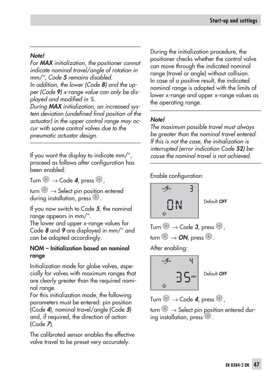
During the initialization procedure, thepositioner checks whether the control valvecan move through the indicated nominalrange (travel or angle) without collision.In case of a positive result, the indicatednominal range is adopted with the limits oflower x-range and upper x-range values asthe operating range.
Note!The maximum possible travel must alwaysbe greater than the nominal travel entered.If this is not the case, the initialization isinterrupted (error indication Code 52) be-cause the nominal travel is not achieved.
Enable configuration:
Default OFF
Turn → Code 3, press ,
turn → ON, press .
After enabling:
Default OFF
Turn → Code 4, press ,
turn → Select pin position entered dur-ing installation, press .
EB 8384-2 EN 47
Start-up and settings
mm
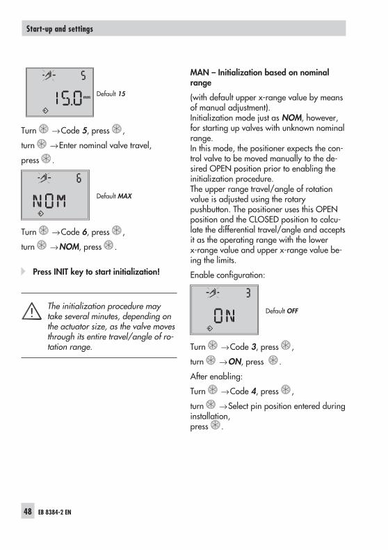
Default 15
Turn →Code 5, press ,
turn →Enter nominal valve travel,
press .
Default MAX
Turn →Code 6, press ,
turn →NOM, press .
Press INIT key to start initialization!
The initialization procedure maytake several minutes, depending onthe actuator size, as the valve movesthrough its entire travel/angle of ro-tation range.
MAN – Initialization based on nominalrange
(with default upper x-range value by meansof manual adjustment).Initialization mode just as NOM, however,for starting up valves with unknown nominalrange.In this mode, the positioner expects the con-trol valve to be moved manually to the de-sired OPEN position prior to enabling theinitialization procedure.The upper range travel/angle of rotationvalue is adjusted using the rotarypushbutton. The positioner uses this OPENposition and the CLOSED position to calcu-late the differential travel/angle and acceptsit as the operating range with the lowerx-range value and upper x-range value be-ing the limits.
Enable configuration:
Default OFF
Turn →Code 3, press ,
turn →ON, press .
After enabling:
Turn →Code 4, press ,
turn →Select pin position entered duringinstallation,press .
48 EB 8384-2 EN
Start-up and settings
mm
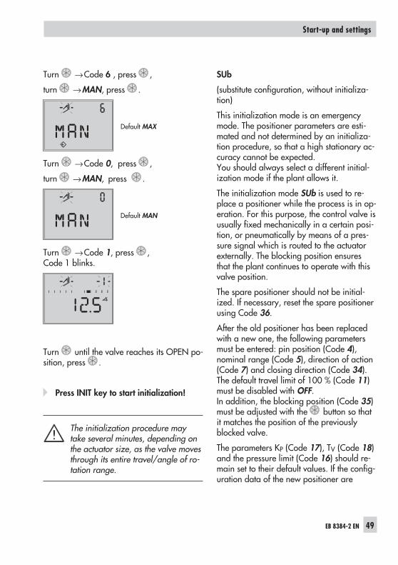
Turn →Code 6 , press ,
turn →MAN, press .
Default MAX
Turn →Code 0, press ,
turn →MAN, press .
Default MAN
Turn →Code 1, press ,Code 1 blinks.
Turn until the valve reaches its OPEN po-sition, press .
Press INIT key to start initialization!
The initialization procedure maytake several minutes, depending onthe actuator size, as the valve movesthrough its entire travel/angle of ro-tation range.
SUb
(substitute configuration, without initializa-tion)
This initialization mode is an emergencymode. The positioner parameters are esti-mated and not determined by an initializa-tion procedure, so that a high stationary ac-curacy cannot be expected.You should always select a different initial-ization mode if the plant allows it.
The initialization mode SUb is used to re-place a positioner while the process is in op-eration. For this purpose, the control valve isusually fixed mechanically in a certain posi-tion, or pneumatically by means of a pres-sure signal which is routed to the actuatorexternally. The blocking position ensuresthat the plant continues to operate with thisvalve position.
The spare positioner should not be initial-ized. If necessary, reset the spare positionerusing Code 36.
After the old positioner has been replacedwith a new one, the following parametersmust be entered: pin position (Code 4),nominal range (Code 5), direction of action(Code 7) and closing direction (Code 34).The default travel limit of 100 % (Code 11)must be disabled with OFF.In addition, the blocking position (Code 35)must be adjusted with the button so thatit matches the position of the previouslyblocked valve.
The parameters KP (Code 17), TV (Code 18)and the pressure limit (Code 16) should re-main set to their default values. If the config-uration data of the new positioner are
EB 8384-2 EN 49
Start-up and settings
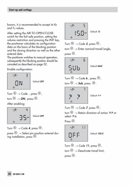
known, it is recommended to accept its KPand TV values.
After setting the AIR TO OPEN/CLOSEswitch for the fail-safe position, setting thevolume restriction and pressing the INIT key,the positioner calculates its configurationdata on the basis of the blocking positionand the closing direction as well as the otherentered data.The positioner switches to manual operation,subsequently the blocking position should becanceled as described on page 52.
Enable configuration:
Default OFF
Turn → Code , press ,
turn → ON, press .
After enabling:
Default OFF
Turn → Code 4, press ,
press → Select pin position entered dur-ing installation, press .
Default 15
Turn → Code 5, press ,
turn → Enter nominal travel/angle,
press .
Default MAX
Turn → Code 6 , press ,
turn → Sub, press .
Default
Turn → Code 7, press ,
turn → Retain direction of action orselect .
Press .
Default 100.0
Turn → Code 11, press ,
turn → Deactivate travel limit,
press .
50 EB 8384-2 EN
Start-up and settings
mm
mm
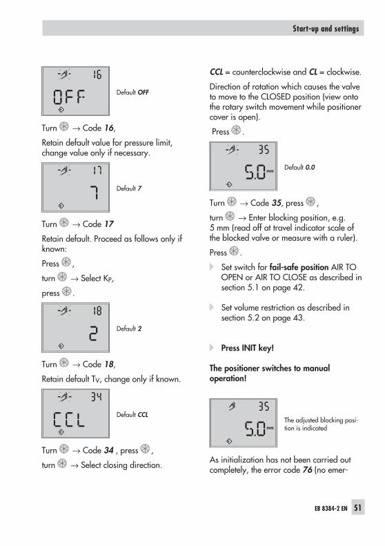
Default OFF
Turn → Code 16,
Retain default value for pressure limit,change value only if necessary.
Default 7
Turn → Code 17
Retain default. Proceed as follows only ifknown:
Press ,
turn → Select KP,
press .
Default 2
Turn → Code 18,
Retain default TV, change only if known.
Default CCL
Turn → Code 34 , press ,
turn → Select closing direction.
CCL = counterclockwise and CL = clockwise.
Direction of rotation which causes the valveto move to the CLOSED position (view ontothe rotary switch movement while positionercover is open).
Press .
Default 0.0
Turn → Code 35, press ,
turn → Enter blocking position, e.g.5 mm (read off at travel indicator scale ofthe blocked valve or measure with a ruler).
Press .
Set switch for fail-safe position AIR TOOPEN or AIR TO CLOSE as described insection 5.1 on page 42.
Set volume restriction as described insection 5.2 on page 43.
Press INIT key!
The positioner switches to manualoperation!
The adjusted blocking posi-tion is indicated
As initialization has not been carried outcompletely, the error code 76 (no emer-
EB 8384-2 EN 51
Start-up and settings
mm
mm
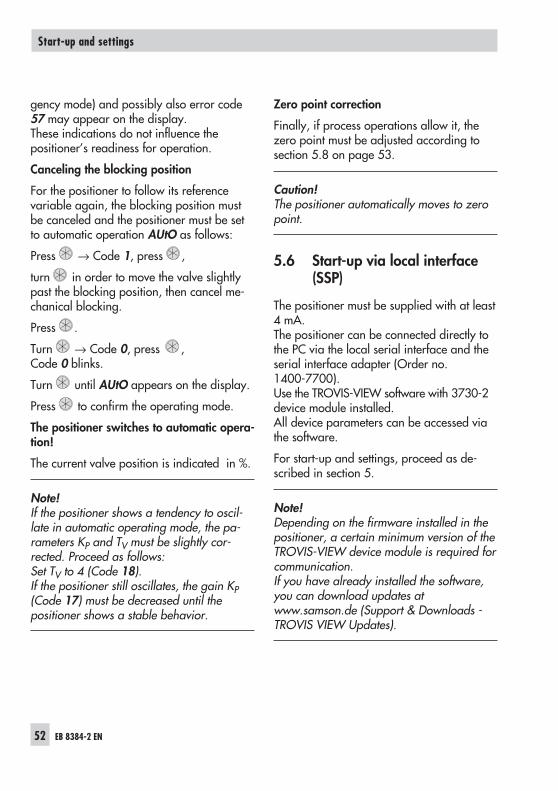
gency mode) and possibly also error code57 may appear on the display.These indications do not influence thepositioner’s readiness for operation.
Canceling the blocking position
For the positioner to follow its referencevariable again, the blocking position mustbe canceled and the positioner must be setto automatic operation AUtO as follows:
Press → Code 1, press ,
turn in order to move the valve slightlypast the blocking position, then cancel me-chanical blocking.
Press .
Turn → Code 0, press ,Code 0 blinks.
Turn until AUtO appears on the display.
Press to confirm the operating mode.
The positioner switches to automatic opera-tion!
The current valve position is indicated in %.
Note!If the positioner shows a tendency to oscil-late in automatic operating mode, the pa-rameters KP and TV must be slightly cor-rected. Proceed as follows:Set TV to 4 (Code 18).If the positioner still oscillates, the gain KP(Code 17) must be decreased until thepositioner shows a stable behavior.
Zero point correction
Finally, if process operations allow it, thezero point must be adjusted according tosection 5.8 on page 53.
Caution!The positioner automatically moves to zeropoint.
5.6 Start-up via local interface(SSP)
The positioner must be supplied with at least4 mA.The positioner can be connected directly tothe PC via the local serial interface and theserial interface adapter (Order no.1400-7700).Use the TROVIS-VIEW software with 3730-2device module installed.All device parameters can be accessed viathe software.
For start-up and settings, proceed as de-scribed in section 5.
Note!Depending on the firmware installed in thepositioner, a certain minimum version of theTROVIS-VIEW device module is required forcommunication.If you have already installed the software,you can download updates atwww.samson.de (Support & Downloads -TROVIS VIEW Updates).
52 EB 8384-2 EN
Start-up and settings
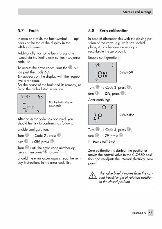
5.7 Faults
In case of a fault, the fault symbol ap-pears at the top of the display in theleft-hand corner.
Additionally, for some faults a signal isissued via the fault alarm contact (see errorcode list).
To access the error codes, turn the but-ton past the Code 50.Err appears on the display with the respec-tive error code.For the cause of the fault and its remedy, re-fer to the codes listed in section 11.
Display indicating anerror code
After an error code has occurred, youshould first try to confirm it as follows:
Enable configuration:
Turn → Code 3 , press ,
turn → ON, press .
Turn until the error code number ap-pears, then press to confirm it.
Should the error occur again, read the rem-edy instructions in the error code list.
5.8 Zero calibration
In case of discrepancies with the closing po-sition of the valve, e.g. with soft-sealedplugs, it may become necessary torecalibrate the zero point.
Enable configuration:
Default OFF
Turn → Code 3, press ,
turn → ON, press .
After enabling:
Default MAX
Turn → Code 6, press ,
turn → ZP, press .
Press INIT key!
Zero calibration is started, the positionermoves the control valve to the CLOSED posi-tion and readjusts the internal electrical zeropoint.
The valve briefly moves from the cur-rent travel/angle of rotation positionto the closed position.
EB 8384-2 EN 53
Start-up and settings
S
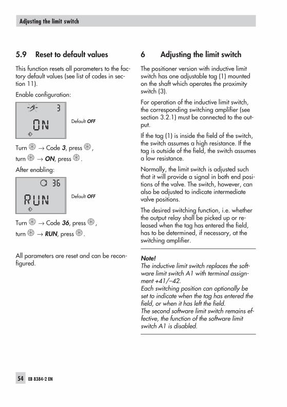
5.9 Reset to default values
This function resets all parameters to the fac-tory default values (see list of codes in sec-tion 11).
Enable configuration:
Default OFF
Turn → Code 3, press ,
turn → ON, press .
After enabling:
Default OFF
Turn → Code 36, press ,
turn → RUN, press .
All parameters are reset and can be recon-figured.
6 Adjusting the limit switch
The positioner version with inductive limitswitch has one adjustable tag (1) mountedon the shaft which operates the proximityswitch (3).
For operation of the inductive limit switch,the corresponding switching amplifier (seesection 3.2.1) must be connected to the out-put.
If the tag (1) is inside the field of the switch,the switch assumes a high resistance. If thetag is outside of the field, the switch assumesa low resistance.
Normally, the limit switch is adjusted suchthat it will provide a signal in both end posi-tions of the valve. The switch, however, canalso be adjusted to indicate intermediatevalve positions.
The desired switching function, i.e. whetherthe output relay shall be picked up or re-leased when the tag has entered the field,has to be determined, if necessary, at theswitching amplifier.
Note!The inductive limit switch replaces the soft-ware limit switch A1 with terminal assign-ment +41/–42.Each switching position can optionally beset to indicate when the tag has entered thefield, or when it has left the field.The second software limit switch remains ef-fective, the function of the software limitswitch A1 is disabled.
54 EB 8384-2 EN
Adjusting the limit switch
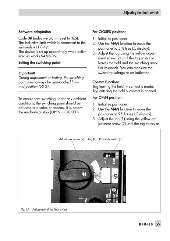
Software adaptation
Code 38 (inductive alarm is set to YES).The inductive limit switch is connected to theterminals +41/–42.The device is set up accordingly when deliv-ered ex works SAMSON.
Setting the switching point:
Important!During adjustment or testing, the switchingpoint must always be approached frommid-position (50 %).
To ensure safe switching under any ambientconditions, the switching point should beadjusted to a value of approx. 5 % beforethe mechanical stop (OPEN – CLOSED).
For CLOSED position:
1. Initialize positioner.2. Use the MAN function to move the
positioner to 5 % (see LC display).3. Adjust the tag using the yellow adjust-
ment screw (2) until the tag enters orleaves the field and the switching ampli-fier responds. You can measure theswitching voltage as an indicator.
Contact function:Tag leaving the field > contact is made.Tag entering the field > contact is opened.
For OPEN position:
1. Initialize positioner.2. Use the MAN function to move the
positioner to 95 % (see LC display).3. Adjust the tag (1) using the yellow ad-
justment screw (2) until the tag enters or
EB 8384-2 EN 55
Adjusting the limit switch
Fig. 17 · Adjustment of the limit switch
Adjustment screw (2) Tag (1) Proximity switch (3)
leaves the field of the proximity switch(3).You can measure the switching voltageas an indicator.
Contact function:
Tag leaving the field > Contact is made.Tag entering the field > Contact is opened.
56 EB 8384-2 EN
Adjusting the limit switch
7 Quick start-up guide
7.1 Mounting
Direct attachment
to SAMSON Type 3277 Actuator
Travel mm Actuator cm2 Pin position
7.5 120 25
15 120/240/350 35
15/30 700 50
Note!Standard delivery includes lever M readyassembled with the follower pin on 35 mmpin position for 15 mm travel!
To mount the positioner, lift the lever so thatthe follower pin rests on the follower clampof the actuator stem.
NAMUR attachment
Determine the maximum travel range ofthe control valve from the closed positionto as far it will go in the other direction.
Select the lever to match the maximumtravel range as well the next largest pinposition and screw onto the shaft of thepositioner.
Lever option/pin distance:see table on page 64 or cover plate onthe positioner.
Screw the NAMUR bracket onto thevalve yoke so that it is aligned centrallyto the slot of the follower plate when thetravel position is at 50 %.
Secure the positioner to the NAMURbracket, making sure that the followerpin is in the slot of the follower plate.Make sure the lever can still move.
Attachment to rotary actuators
Lever M pin position 90° Put the valve into the closed position, de-
termine the opening direction. Place the follower plate on the slotted ac-
tuator shaft and fasten it to the couplingwheel. Attach the top pair of bracketsand the bottom pair of brackets to theactuator.
Place the positioner on the brackets andscrew tight, making sure that the leverwith its follower pin engages the slot ofthe coupling wheel, while taking into ac-count the opening direction.It is important to make sure that the le-ver's mid position corresponds to the midtravel of the valve (lever's mid position =the lever is parallel to the long side of thepositioner casing).
Pneumatic connections
Screw the threaded connections only intothe attached connection block, connect-ing plate or pressure gauge block fromthe accessories.
EB 8384-2 EN 57
Quick start-up guide
7.2 Start-up
Connect pneumatic supply air (1.4 to6 bar).
Apply an electrical reference variable (4 to20 mA).
Set the fail-safe position
Position the slide switch according tofail-safe position of the control valve:AIR TO OPEN or AIR TO CLOSE.
Adapt the volume restriction Q to the actu-ator size
Only set the restriction for actuators< 240 cm2 to:MIN SIDE for connection at the side orMIN BACK for connection at the back.
Note!After each change of the volume restrictionsetting, the positioner must be re-initialized.
Changing the reading direction of thedisplay
(if necessary)
Turn → Code 2 , press ,
turn → Display ok, press .
Operation
Selecting the parameters or values
Each parameter has a code number whichis shown in the display. Use the button toselect.Turn the button to select parameters or val-ues and then push to confirm.
Select and confirm ESC to prevent an en-tered value from being accepted.
Enabling parameters
Parameters that have a code marked withan asterisk (*) can only be changed whenthey are enabled beforehand using Code 3.
The configuration mode is shown in the dis-play with the symbol.
See list of codes from page 62 onwards orcover plate of the positioner for a descrip-tion of the menu codes.
58 EB 8384-2 EN
Quick start-up guide
7.3 Initialization
Important!Perform a reset (Code 36) prior to each ini-tialization
Turn → Code 3, ↵
turn → ON, ↵
turn → Code 36, ↵
select RUN, ↵
Caution!During initialization, the valve runs throughits whole range of travel/angle of rotation.
7.3.1 Simplest method (MAX)
Mount and start up the positioner andpress the INIT key!READY!The positioner adapts itself automatically tothe maximum travel/angle of rotationrange of the control valve.
7.3.2 Precise method (NOM)
Positioner adapts itself precisely to the nomi-nal travel/rotational angle of the controlvalve!
Mount and start up the positioner, then pro-ceed as follows:
Turn → Code 3, ↵
turn → ON, ↵
turn → Code 4, ↵Select pin position, ↵
turn → Code 5, ↵
Enter nominal travel/range, ↵
turn → Code 6, ↵
select NOM, ↵
Press INIT key!
7.3.3 Manual method (MAN)
Initialization mode same as NOM, but forstart-up of control valves with unknownnominal ranges. The final position oftravel/angle of rotation (valve open) is en-tered manually.
Mount and start up the positioner, then pro-ceed as follows:
Turn → Code 0, ↵,
turn → select MAN, ↵
turn → Code 1, ↵,
turn → valve open position, ↵
turn → Code 3, ↵,
turn → ON, ↵
turn → Code 6, ↵, select MAN, ↵
Press INIT key!
Note!After imposing the electrical reference vari-able, the positioner is in the last used oper-ating mode. Code 0 appears in the display.If the positioner has not yet been initialized,the symbol blinks.
EB 8384-2 EN 59
Quick start-up guide
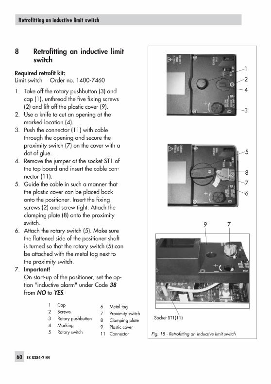
8 Retrofitting an inductive limitswitch
Required retrofit kit:Limit switch Order no. 1400-7460
1. Take off the rotary pushbutton (3) andcap (1), unthread the five fixing screws(2) and lift off the plastic cover (9).
2. Use a knife to cut an opening at themarked location (4).
3. Push the connector (11) with cablethrough the opening and secure theproximity switch (7) on the cover with adot of glue.
4. Remove the jumper at the socket ST1 ofthe top board and insert the cable con-nector (11).
5. Guide the cable in such a manner thatthe plastic cover can be placed backonto the positioner. Insert the fixingscrews (2) and screw tight. Attach theclamping plate (8) onto the proximityswitch.
6. Attach the rotary switch (5). Make surethe flattened side of the positioner shaftis turned so that the rotary switch (5) canbe attached with the metal tag next tothe proximity switch.
7. Important!On start-up of the positioner, set the op-tion "inductive alarm" under Code 38from NO to YES.
60 EB 8384-2 EN
Retrofitting an inductive limit switch
Fig. 18 · Retrofitting an inductive limit switch
Socket ST1(11)
9 7
1
2
4
3
5
8
7
6
1 Cap2 Screws3 Rotary pushbutton4 Marking5 Rotary switch
6 Metal tag7 Proximity switch8 Clamping plate9 Plastic cover11 Connector
9 Maintenance
The positioner does not require any mainte-nance.
There are filters with a 100 mm mesh size inthe pneumatic connections for supply andoutput which can be removed and cleaned,if required.
The maintenance instructions of any up-stream supply air pressure reducing stationsmust be observed.
10 Servicing explosion-protecteddevices
If a part of the positioner on which the ex-plosion protection is based needs to be ser-viced, the positioner must not be put backinto operation until an expert has inspectedthe device according to explosion protectionrequirements, has issued a certificate statingthis or given the device a mark of confor-mity.
Inspection by an expert is not required if themanufacturer performs a routine check onthe device prior to putting it back into oper-ation. The passing of the routine check mustbe documented by attaching a mark of con-formity to the device.
Devices that have already been used outsideof hazardous areas and are intended foruse in hazardous areas in future must com-ply with the safety demands placed on re-paired devices. Prior to operation, they mustbe tested according to the specificationsstipulated for "Repairing explosion-pro-tected devices".
EB 8384-2 EN 61
Maintenance
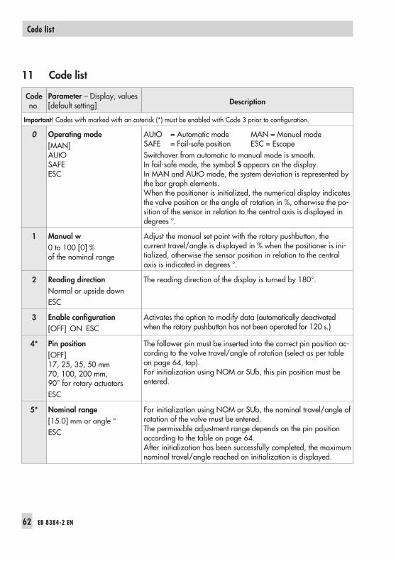
11 Code list
Codeno.
Parameter – Display, values[default setting] Description
Important! Codes with marked with an asterisk (*) must be enabled with Code 3 prior to configuration.
0 Operating mode[MAN]AUtOSAFEESC
AUtO = Automatic mode MAN = Manual modeSAFE = Fail-safe position ESC = EscapeSwitchover from automatic to manual mode is smooth.In fail-safe mode, the symbol S appears on the display.In MAN and AUtO mode, the system deviation is represented bythe bar graph elements.When the positioner is initialized, the numerical display indicatesthe valve position or the angle of rotation in %, otherwise the po-sition of the sensor in relation to the central axis is displayed indegrees °.
1 Manual w0 to 100 [0] %of the nominal range
Adjust the manual set point with the rotary pushbutton, thecurrent travel/angle is displayed in % when the positioner is ini-tialized, otherwise the sensor position in relation to the centralaxis is indicated in degrees °.
2 Reading directionNormal or upside downESC
The reading direction of the display is turned by 180°.
3 Enable configuration[OFF] ON ESC
Activates the option to modify data (automatically deactivatedwhen the rotary pushbutton has not been operated for 120 s.)
4* Pin position[OFF]17, 25, 35, 50 mm70, 100, 200 mm,90° for rotary actuatorsESC
The follower pin must be inserted into the correct pin position ac-cording to the valve travel/angle of rotation (select as per tableon page 64, top).For initialization using NOM or SUb, this pin position must beentered.
5* Nominal range[15.0] mm or angle °ESC
For initialization using NOM or SUb, the nominal travel/angle ofrotation of the valve must be entered.The permissible adjustment range depends on the pin positionaccording to the table on page 64.After initialization has been successfully completed, the maximumnominal travel/angle reached on initialization is displayed.
62 EB 8384-2 EN
Code list
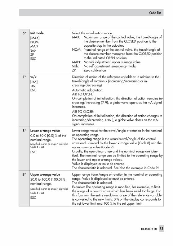
6* Init mode[MAX]NOMMANSubZPESC
Select the initialization modeMAX: Maximum range of the control valve, the travel/angle of
the closure member from the CLOSED position to theopposite stop in the actuator.
NOM: Nominal range of the control valve, the travel/angle ofthe closure member measured from the CLOSED positionto the indicated OPEN position.
MAN: Manual adjustment: upper x-range valueSUb: No self-adjustment (emergency mode)ZP: Zero calibration
7* w/x[]
ESC
Direction of action of the reference variable w in relation to thetravel/angle of rotation x (increasing/increasing or in-creasing/decreasing)Automatic adaptation:AIR TO OPEN:On completion of initialization, the direction of action remains in-creasing/increasing (), a globe valve opens as the mA signalincreases.AIR TO CLOSE:On completion of initialization, the direction of action changes toincreasing/decreasing ( ), a globe valve closes as the mAsignal increases.
8* Lower x-range value0.0 to 80.0 [0.0] % of thenominal range,Specified in mm or angle ° providedCode 4 is set
ESC
Lower range value for the travel/angle of rotation in the nominalor operating range.The operating range is the actual travel/angle of the controlvalve and is limited by the lower x-range value (Code 8) and theupper x-range value (Code 9).Usually, the operating range and the nominal range are iden-tical. The nominal range can be limited to the operating range bythe lower and upper x-range values.Value is displayed or must be entered.The characteristic is adapted. See also the example in Code 9!
9* Upper x-range value20.0 to 100.0 [100.0] %nominal range,Specified in mm or angle ° provided
Code 4 is set
ESC
Upper range travel/angle of rotation in the nominal or operatingrange. Value is displayed or must be entered.The characteristic is adapted.Example: The operating range is modified, for example, to limitthe range of a control valve which has been sized too large. Forthis function, the entire resolution range of the reference variableis converted to the new limits. 0 % on the display corresponds tothe set lower limit and 100 % to the set upper limit.
EB 8384-2 EN 63
Code list
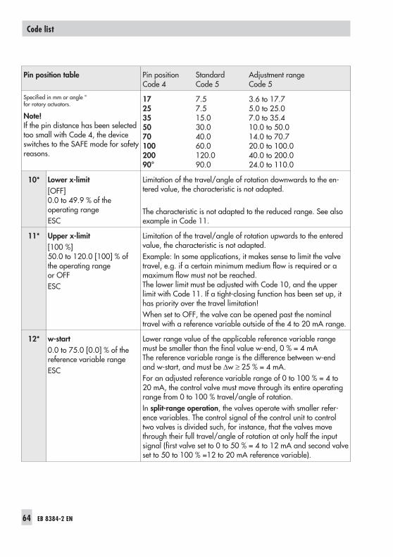
Pin position table Pin position Standard Adjustment rangeCode 4 Code 5 Code 5
Specified in mm or angle °for rotary actuators.
Note!If the pin distance has been selectedtoo small with Code 4, the deviceswitches to the SAFE mode for safetyreasons.
17 7.5 3.6 to 17.725 7.5 5.0 to 25.035 15.0 7.0 to 35.450 30.0 10.0 to 50.070 40.0 14.0 to 70.7100 60.0 20.0 to 100.0200 120.0 40.0 to 200.090° 90.0 24.0 to 110.0
10* Lower x-limit[OFF]0.0 to 49.9 % of theoperating rangeESC
Limitation of the travel/angle of rotation downwards to the en-tered value, the characteristic is not adapted.
The characteristic is not adapted to the reduced range. See alsoexample in Code 11.
11* Upper x-limit[100 %]50.0 to 120.0 [100] % ofthe operating rangeor OFFESC
Limitation of the travel/angle of rotation upwards to the enteredvalue, the characteristic is not adapted.Example: In some applications, it makes sense to limit the valvetravel, e.g. if a certain minimum medium flow is required or amaximum flow must not be reached.The lower limit must be adjusted with Code 10, and the upperlimit with Code 11. If a tight-closing function has been set up, ithas priority over the travel limitation!When set to OFF, the valve can be opened past the nominaltravel with a reference variable outside of the 4 to 20 mA range.
12* w-start0.0 to 75.0 [0.0] % of thereference variable rangeESC
Lower range value of the applicable reference variable rangemust be smaller than the final value w-end, 0 % = 4 mAThe reference variable range is the difference between w-endand w-start, and must be ∆w ≥ 25 % = 4 mA.For an adjusted reference variable range of 0 to 100 % = 4 to20 mA, the control valve must move through its entire operatingrange from 0 to 100 % travel/angle of rotation.In split-range operation, the valves operate with smaller refer-ence variables. The control signal of the control unit to controltwo valves is divided such, for instance, that the valves movethrough their full travel/angle of rotation at only half the inputsignal (first valve set to 0 to 50 % = 4 to 12 mA and second valveset to 50 to 100 % =12 to 20 mA reference variable).
64 EB 8384-2 EN
Code list
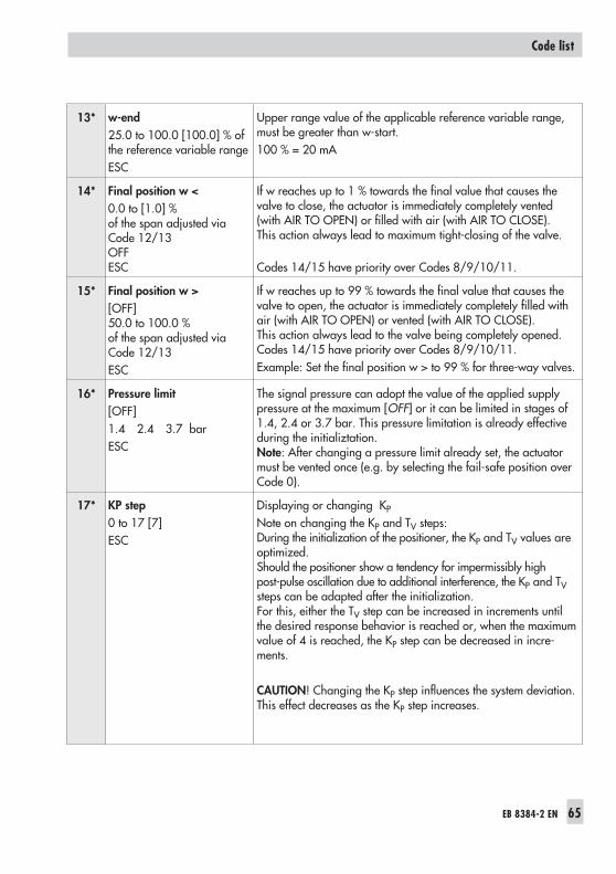
13* w-end25.0 to 100.0 [100.0] % ofthe reference variable rangeESC
Upper range value of the applicable reference variable range,must be greater than w-start.100 % = 20 mA
14* Final position w <0.0 to [1.0] %of the span adjusted viaCode 12/13OFFESC
If w reaches up to 1 % towards the final value that causes thevalve to close, the actuator is immediately completely vented(with AIR TO OPEN) or filled with air (with AIR TO CLOSE).This action always lead to maximum tight-closing of the valve.
Codes 14/15 have priority over Codes 8/9/10/11.
15* Final position w >[OFF]50.0 to 100.0 %of the span adjusted viaCode 12/13ESC
If w reaches up to 99 % towards the final value that causes thevalve to open, the actuator is immediately completely filled withair (with AIR TO OPEN) or vented (with AIR TO CLOSE).This action always lead to the valve being completely opened.Codes 14/15 have priority over Codes 8/9/10/11.Example: Set the final position w > to 99 % for three-way valves.
16* Pressure limit[OFF]1.4 2.4 3.7 barESC
The signal pressure can adopt the value of the applied supplypressure at the maximum [OFF] or it can be limited in stages of1.4, 2.4 or 3.7 bar. This pressure limitation is already effectiveduring the initializtation.Note: After changing a pressure limit already set, the actuatormust be vented once (e.g. by selecting the fail-safe position overCode 0).
17* KP step0 to 17 [7]ESC
Displaying or changing KP
Note on changing the KP and TV steps:During the initialization of the positioner, the KP and TV values areoptimized.Should the positioner show a tendency for impermissibly highpost-pulse oscillation due to additional interference, the KP and TVsteps can be adapted after the initialization.For this, either the TV step can be increased in increments untilthe desired response behavior is reached or, when the maximumvalue of 4 is reached, the KP step can be decreased in incre-ments.
CAUTION! Changing the KP step influences the system deviation.This effect decreases as the KP step increases.
EB 8384-2 EN 65
Code list
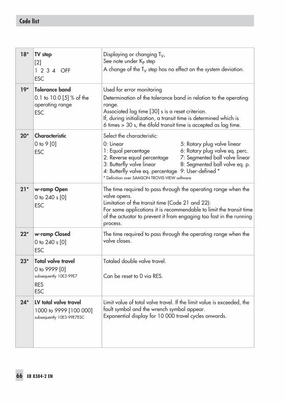
18* TV step[2]1 2 3 4 OFFESC
Displaying or changing TV,See note under KP stepA change of the TV step has no effect on the system deviation.
19* Tolerance band0.1 to 10.0 [5] % of theoperating rangeESC
Used for error monitoringDetermination of the tolerance band in relation to the operatingrange.Associated lag time [30] s is a reset criterion.If, during initialization, a transit time is determined which is6 times > 30 s, the 6fold transit time is accepted as lag time.
20* Characteristic0 to 9 [0]ESC
Select the characteristic:0: Linear 5: Rotary plug valve linear1: Equal percentage 6: Rotary plug valve eq. perc.2: Reverse equal percentage 7: Segmented ball valve linear3: Butterfly valve linear 8: Segmented ball valve eq. p.4: Butterfly valve eq. percentage 9: User-defined ** Definition over SAMSON TROVIS-VIEW software
21* w-ramp Open0 to 240 s [0]ESC
The time required to pass through the operating range when thevalve opens.Limitation of the transit time (Code 21 and 22):For some applications it is recommendable to limit the transit timeof the actuator to prevent it from engaging too fast in the runningprocess.
22* w-ramp Closed0 to 240 s [0]ESC
The time required to pass through the operating range when thevalve closes.
23* Total valve travel0 to 9999 [0]subsequently 10E3-99E7
RESESC
Totaled double valve travel.
Can be reset to 0 via RES.
24* LV total valve travel1000 to 9999 [100 000]subsequently 10E3-99E7ESC
Limit value of total valve travel. If the limit value is exceeded, thefault symbol and the wrench symbol appear.Exponential display for 10 000 travel cycles onwards.
66 EB 8384-2 EN
Code list
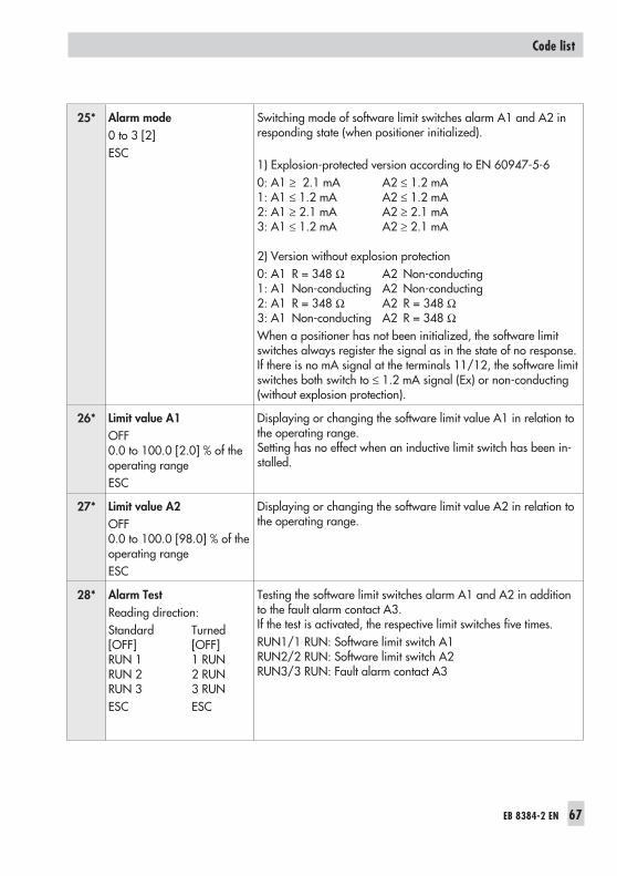
25* Alarm mode0 to 3 [2]ESC
Switching mode of software limit switches alarm A1 and A2 inresponding state (when positioner initialized).
1) Explosion-protected version according to EN 60947-5-60: A1 ≥ 2.1 mA A2 ≤ 1.2 mA1: A1 ≤ 1.2 mA A2 ≤ 1.2 mA2: A1 ≥ 2.1 mA A2 ≥ 2.1 mA3: A1 ≤ 1.2 mA A2 ≥ 2.1 mA
2) Version without explosion protection0: A1 R = 348 Ω A2 Non-conducting1: A1 Non-conducting A2 Non-conducting2: A1 R = 348 Ω A2 R = 348 Ω3: A1 Non-conducting A2 R = 348 ΩWhen a positioner has not been initialized, the software limitswitches always register the signal as in the state of no response.If there is no mA signal at the terminals 11/12, the software limitswitches both switch to ≤ 1.2 mA signal (Ex) or non-conducting(without explosion protection).
26* Limit value A1OFF0.0 to 100.0 [2.0] % of theoperating rangeESC
Displaying or changing the software limit value A1 in relation tothe operating range.Setting has no effect when an inductive limit switch has been in-stalled.
27* Limit value A2OFF0.0 to 100.0 [98.0] % of theoperating rangeESC
Displaying or changing the software limit value A2 in relation tothe operating range.
28* Alarm TestReading direction:Standard Turned[OFF] [OFF]RUN 1 1 RUNRUN 2 2 RUNRUN 3 3 RUNESC ESC
Testing the software limit switches alarm A1 and A2 in additionto the fault alarm contact A3.If the test is activated, the respective limit switches five times.RUN1/1 RUN: Software limit switch A1RUN2/2 RUN: Software limit switch A2RUN3/3 RUN: Fault alarm contact A3
EB 8384-2 EN 67
Code list
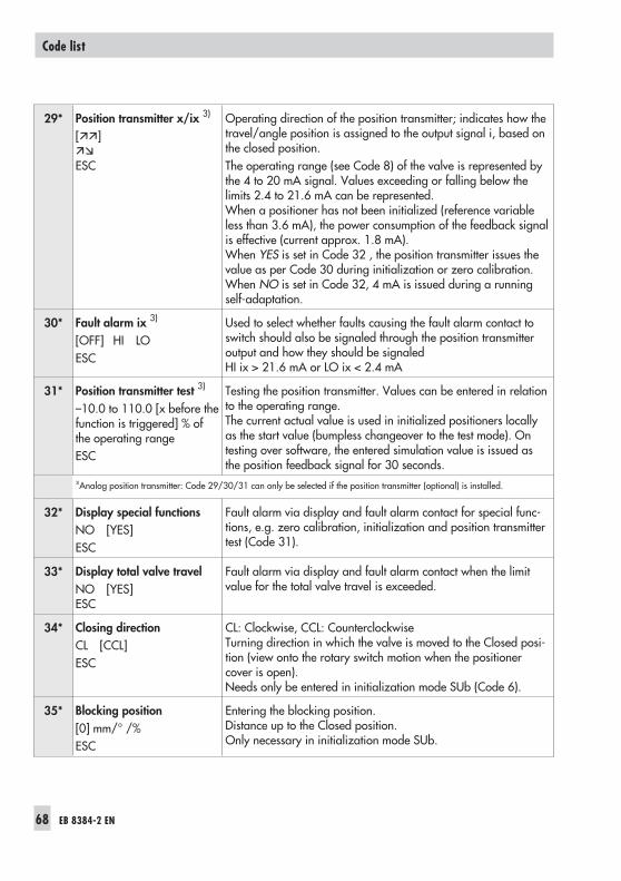
29* Position transmitter x/ix 3)
[]
ESC
Operating direction of the position transmitter; indicates how thetravel/angle position is assigned to the output signal i, based onthe closed position.The operating range (see Code 8) of the valve is represented bythe 4 to 20 mA signal. Values exceeding or falling below thelimits 2.4 to 21.6 mA can be represented.When a positioner has not been initialized (reference variableless than 3.6 mA), the power consumption of the feedback signalis effective (current approx. 1.8 mA).When YES is set in Code 32 , the position transmitter issues thevalue as per Code 30 during initialization or zero calibration.When NO is set in Code 32, 4 mA is issued during a runningself-adaptation.
30* Fault alarm ix 3)
[OFF] HI LOESC
Used to select whether faults causing the fault alarm contact toswitch should also be signaled through the position transmitteroutput and how they should be signaledHI ix > 21.6 mA or LO ix < 2.4 mA
31* Position transmitter test 3)
–10.0 to 110.0 [x before thefunction is triggered] % ofthe operating rangeESC
Testing the position transmitter. Values can be entered in relationto the operating range.The current actual value is used in initialized positioners locallyas the start value (bumpless changeover to the test mode). Ontesting over software, the entered simulation value is issued asthe position feedback signal for 30 seconds.
3)Analog position transmitter: Code 29/30/31 can only be selected if the position transmitter (optional) is installed.
32* Display special functionsNO [YES]ESC
Fault alarm via display and fault alarm contact for special func-tions, e.g. zero calibration, initialization and position transmittertest (Code 31).
33* Display total valve travelNO [YES]ESC
Fault alarm via display and fault alarm contact when the limitvalue for the total valve travel is exceeded.
34* Closing directionCL [CCL]ESC
CL: Clockwise, CCL: CounterclockwiseTurning direction in which the valve is moved to the Closed posi-tion (view onto the rotary switch motion when the positionercover is open).Needs only be entered in initialization mode SUb (Code 6).
35* Blocking position[0] mm/° /%ESC
Entering the blocking position.Distance up to the Closed position.Only necessary in initialization mode SUb.
68 EB 8384-2 EN
Code list
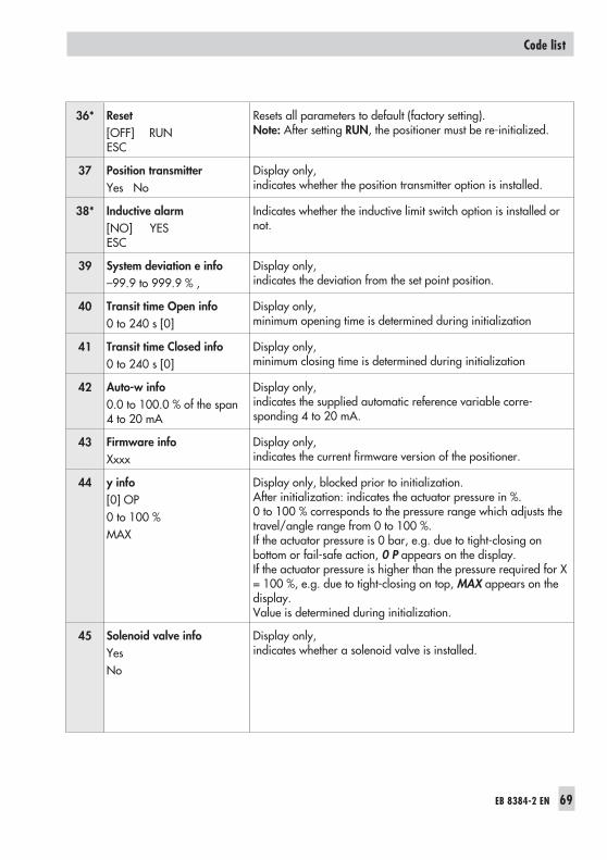
36* Reset[OFF] RUNESC
Resets all parameters to default (factory setting).Note: After setting RUN, the positioner must be re-initialized.
37 Position transmitterYes No
Display only,indicates whether the position transmitter option is installed.
38* Inductive alarm[NO] YESESC
Indicates whether the inductive limit switch option is installed ornot.
39 System deviation e info–99.9 to 999.9 % ,
Display only,indicates the deviation from the set point position.
40 Transit time Open info0 to 240 s [0]
Display only,minimum opening time is determined during initialization
41 Transit time Closed info0 to 240 s [0]
Display only,minimum closing time is determined during initialization
42 Auto-w info0.0 to 100.0 % of the span4 to 20 mA
Display only,indicates the supplied automatic reference variable corre-sponding 4 to 20 mA.
43 Firmware infoXxxx
Display only,indicates the current firmware version of the positioner.
44 y info[0] OP0 to 100 %MAX
Display only, blocked prior to initialization.After initialization: indicates the actuator pressure in %.0 to 100 % corresponds to the pressure range which adjusts thetravel/angle range from 0 to 100 %.If the actuator pressure is 0 bar, e.g. due to tight-closing onbottom or fail-safe action, 0 P appears on the display.If the actuator pressure is higher than the pressure required for X= 100 %, e.g. due to tight-closing on top, MAX appears on thedisplay.Value is determined during initialization.
45 Solenoid valve infoYesNo
Display only,indicates whether a solenoid valve is installed.
EB 8384-2 EN 69
Code list
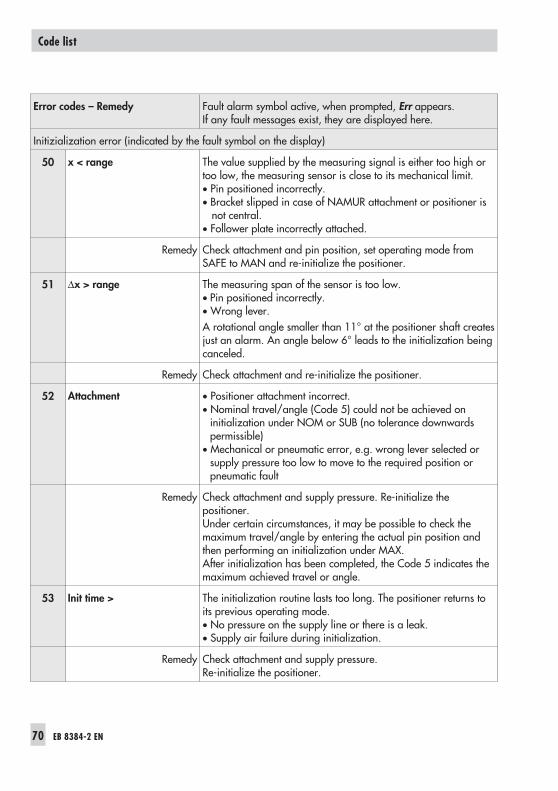
Error codes – Remedy Fault alarm symbol active, when prompted, Err appears.If any fault messages exist, they are displayed here.
Initizialization error (indicated by the fault symbol on the display)
50 x < range The value supplied by the measuring signal is either too high ortoo low, the measuring sensor is close to its mechanical limit.• Pin positioned incorrectly.• Bracket slipped in case of NAMUR attachment or positioner is
not central.• Follower plate incorrectly attached.
Remedy Check attachment and pin position, set operating mode fromSAFE to MAN and re-initialize the positioner.
51 x > range The measuring span of the sensor is too low.• Pin positioned incorrectly.• Wrong lever.A rotational angle smaller than 11° at the positioner shaft createsjust an alarm. An angle below 6° leads to the initialization beingcanceled.
Remedy Check attachment and re-initialize the positioner.
52 Attachment • Positioner attachment incorrect.• Nominal travel/angle (Code 5) could not be achieved on
initialization under NOM or SUB (no tolerance downwardspermissible)
• Mechanical or pneumatic error, e.g. wrong lever selected orsupply pressure too low to move to the required position orpneumatic fault
Remedy Check attachment and supply pressure. Re-initialize thepositioner.Under certain circumstances, it may be possible to check themaximum travel/angle by entering the actual pin position andthen performing an initialization under MAX.After initialization has been completed, the Code 5 indicates themaximum achieved travel or angle.
53 Init time > The initialization routine lasts too long. The positioner returns toits previous operating mode.• No pressure on the supply line or there is a leak.• Supply air failure during initialization.
Remedy Check attachment and supply pressure.Re-initialize the positioner.
70 EB 8384-2 EN
Code list
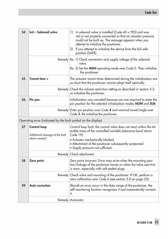
54 Init – Solenoid valve 1) A solenoid valve is installed (Code 45 = YES) and wasnot or not properly connected so that an actuator pressurecould not be built up. The message appears when youattempt to initialize the positioner.
2) If you attempt to initialize the device from the fail-safeposition (SAFE).
Remedy Re. 1) Check connection and supply voltage of the solenoidvalve.
Re. 2) Set the MAN operating mode over Code 0. Then initializethe positioner.
55 Transit time < The actuator transit times determined during the initialization areso short that the positioner cannot adapt itself optimally.
Remedy Check the volume restriction setting as described in section 5.2,re-initialize the positioner.
56 Pin pos. Initialization was canceled because you are required to enter thepin position for the selected initialization modes NOM and SUb.
Remedy Enter pin position over Code 4 and nominal travel/angle overCode 5. Re-initialize the positioner.
Operating error (indicated by the fault symbol on the display)
57 Control loop
Additional message at the faultalarm contact!
Control loop fault, the control valve does not react within the tol-erable times of the controlled variable (tolerance band alarmCode 19).• Actuator mechanically blocked.• Attachment of the positioner subsequently postponed.• Supply pressure not sufficient.
Remedy Check attachment.
58 Zero point Zero point incorrect. Error may arise when the mounting posi-tion/linkage of the positioner moves or when the valve seat trimis worn, especially with soft-sealed plugs.
Remedy Check valve and mounting of the positioner. If OK, perform azero calibration over Code 6 (see section 5.8 on page 53).
59 Auto correction Should an error occur in the data range of the positioner, theself-monitoring function recognizes it and automatically correctsit.
Remedy Automatic
EB 8384-2 EN 71
Code list
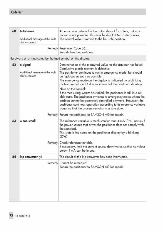
60 Fatal error
Additional message at the faultalarm contact!
An error was detected in the data relevant for safety, auto cor-rection is not possible. This may be due to EMC disturbances.The control valve is moved to the fail-safe position.
Remedy Reset over Code 36.Re-initialize the positioner.
Hardware error (indicated by the fault symbol on the display)
62 x signal
Additional message at the faultalarm contact!
Determination of the measured value for the actuator has failed.Conductive plastic element is defective.The positioner continues to run in emergency mode, but shouldbe replaced as soon as possible.The emergency mode on the display is indicated by a blinkingcontrol symbol and 4 dashes instead of the position indication.Note on the control:If the measuring system has failed, the positioner is still in a reli-able state. The positioner switches to emergency mode where theposition cannot be accurately controlled anymore. However, thepositioner continues operation according to its reference variablesignal so that the process remains in a safe state.
Remedy Return the positioner to SAMSON AG for repair.
63 w too small The reference variable is much smaller than 4 mA (0 %); occurs ifthe power source that drives the positioner does not comply withthe standard.This state is indicated on the positioner display by a blinkingLOW.
Remedy Check reference variable.If necessary, limit the current source downwards so that no valuesbelow 4 mA can be issued.
64 i/p converter (y) The circuit of the i/p converter has been interrupted.
Remedy Cannot be remedied.Return the positioner to SAMSON AG for repair.
72 EB 8384-2 EN
Code list
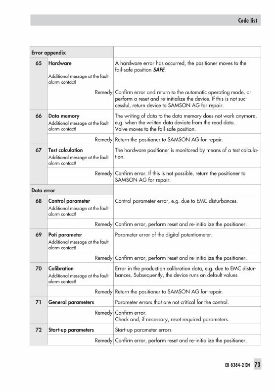
Error appendix
65 Hardware
Additional message at the faultalarm contact!
A hardware error has occurred, the positioner moves to thefail-safe position SAFE.
Remedy Confirm error and return to the automatic operating mode, orperform a reset and re-initialize the device. If this is not suc-cessful, return device to SAMSON AG for repair.
66 Data memoryAdditional message at the faultalarm contact!
The writing of data to the data memory does not work anymore,e.g. when the written data deviate from the read data.Valve moves to the fail-safe position.
Remedy Return the positioner to SAMSON AG for repair.
67 Test calculationAdditional message at the faultalarm contact!
The hardware positioner is monitored by means of a test calcula-tion.
Remedy Confirm error. If this is not possible, return the positioner toSAMSON AG for repair.
Data error
68 Control parameterAdditional message at the faultalarm contact!
Control parameter error, e.g. due to EMC disturbances.
Remedy Confirm error, perform reset and re-initialize the positioner.
69 Poti parameterAdditional message at the faultalarm contact!
Parameter error of the digital potentiometer.
Remedy Confirm error, perform reset and re-initialize the positioner.
70 CalibrationAdditional message at the faultalarm contact!
Error in the production calibration data, e.g. due to EMC distur-bances. Subsequently, the device runs on default values
Remedy Return the positioner to SAMSON AG for repair.
71 General parameters Parameter errors that are not critical for the control.
Remedy Confirm error.Check and, if necessary, reset required parameters.
72 Start-up parameters Start-up parameter errors
Remedy Confirm error, perform reset and re-initialize the positioner.
EB 8384-2 EN 73
Code list
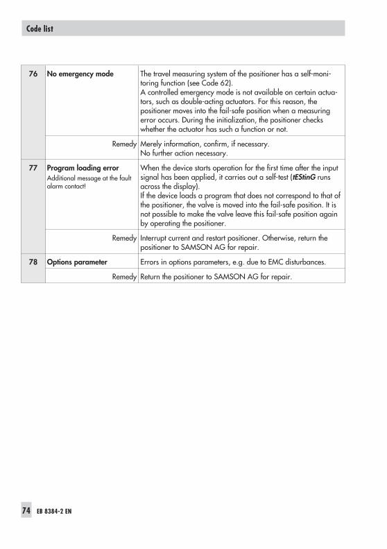
76 No emergency mode The travel measuring system of the positioner has a self-moni-toring function (see Code 62).A controlled emergency mode is not available on certain actua-tors, such as double-acting actuators. For this reason, thepositioner moves into the fail-safe position when a measuringerror occurs. During the initialization, the positioner checkswhether the actuator has such a function or not.
Remedy Merely information, confirm, if necessary.No further action necessary.
77 Program loading errorAdditional message at the faultalarm contact!
When the device starts operation for the first time after the inputsignal has been applied, it carries out a self-test (tEStinG runsacross the display).If the device loads a program that does not correspond to that ofthe positioner, the valve is moved into the fail-safe position. It isnot possible to make the valve leave this fail-safe position againby operating the positioner.
Remedy Interrupt current and restart positioner. Otherwise, return thepositioner to SAMSON AG for repair.
78 Options parameter Errors in options parameters, e.g. due to EMC disturbances.
Remedy Return the positioner to SAMSON AG for repair.
74 EB 8384-2 EN
Code list
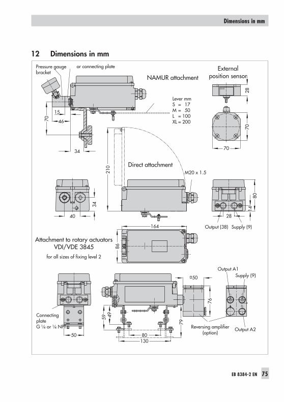
12 Dimensions in mm
EB 8384-2 EN 75
Dimensions in mm
or connecting plate
A1 Z
A2
40
34
210
28
1480
164 Output (38) Supply (9)
86
70
15
46
34 70
7028
Schild
Output A1
Output A2
Supply (9)
50 80130
4959
79
76
50
Direct attachment
NAMUR attachmentExternal
position sensor
Pressure gaugebracket
Lever mmS = 17M = 50L = 100XL = 200
ConnectingplateG ¼ or ¼ NPT Reversing amplifier
(option)
M20 x 1.5
Attachment to rotary actuatorsVDI/VDE 3845
for all sizes of fixing level 2
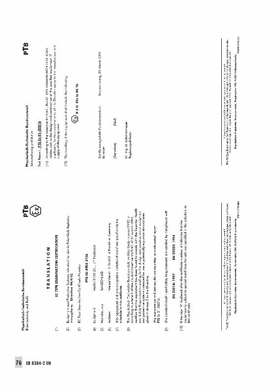
76 EB 8384-2 EN
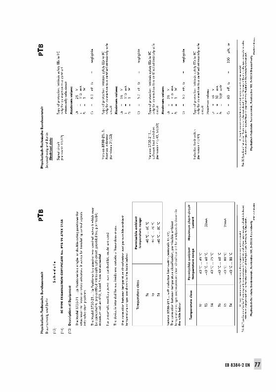
EB 8384-2 EN 77
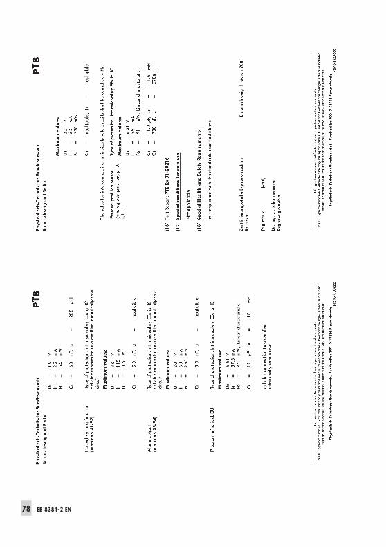
78 EB 8384-2 EN
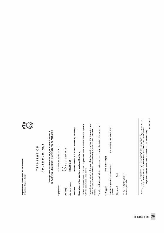
EB 8384-2 EN 79
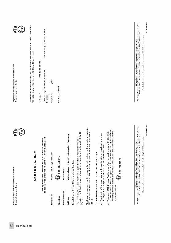
80 EB 8384-2 EN
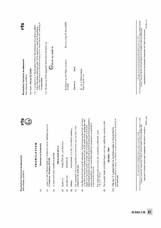
EB 8384-2 EN 81
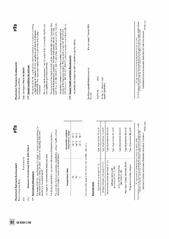
82 EB 8384-2 EN
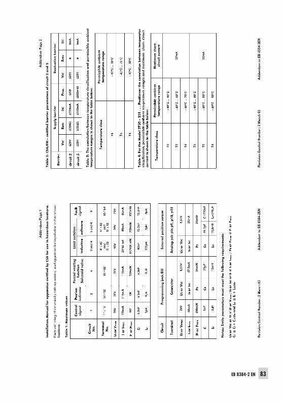
EB 8384-2 EN 83
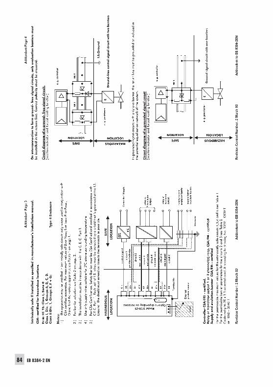
84 EB 8384-2 EN
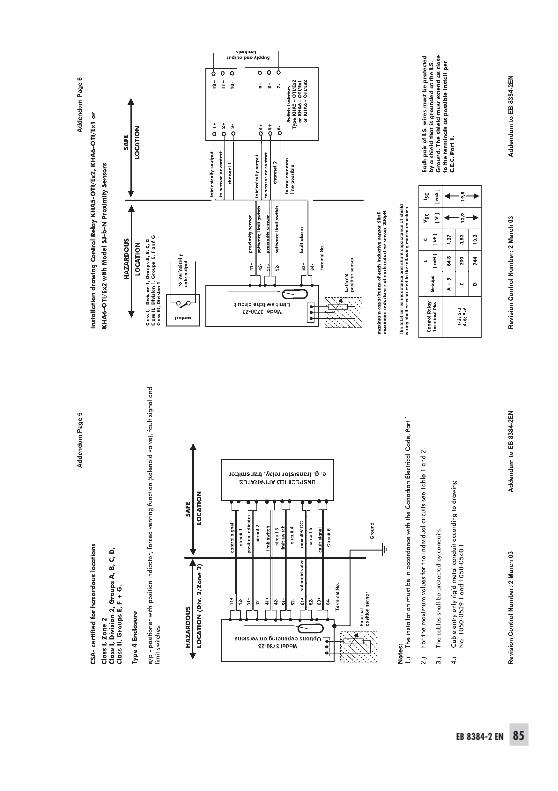
EB 8384-2 EN 85

86 EB 8384-2 EN

EB 8384-2 EN 87

SAMSON AG · MESS- UND REGELTECHNIKWeismüllerstraße 3 · 60314 Frankfurt am Main · GermanyPhone: + 49 69 4009-0 · Fax: +49 69 4009-1507Internet: http://www.samson.de EB 8384-2 EN S/
Z20
04-1
2