Embed Size (px)
Citation preview
787
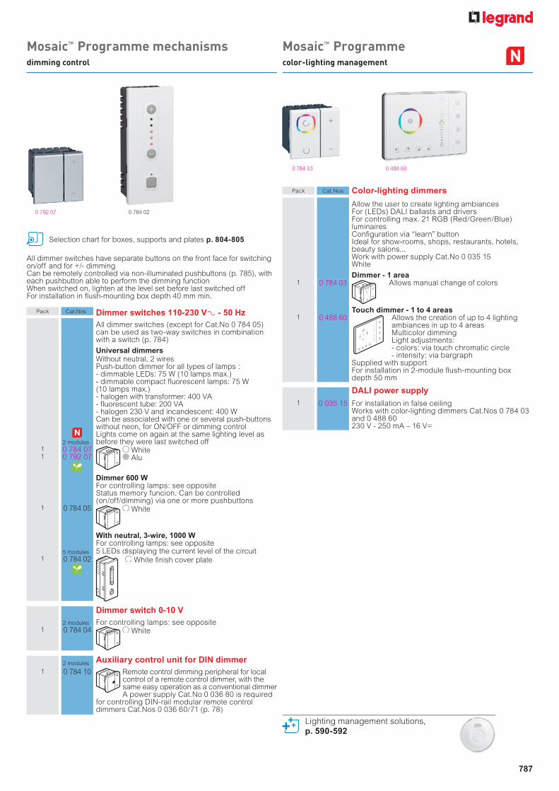
MosaicTM Programmecolor-lighting management
MosaicTM Programme mechanismsdimming control
Lighting management solutions,p. 590-592
0 792 07
0 784 03 0 488 60
0 784 02
Selection chart for boxes, supports and plates p. 804-805
All dimmer switches have separate buttons on the front face for switching on/off and for +/- dimmingCan be remotely controlled via non-illuminated pushbuttons (p. 785), with each pushbutton able to perform the dimming functionWhen switched on, lighten at the level set before last switched offFor installation in flush-mounting box depth 40 mm min.
Pack Cat.Nos Dimmer switches 110-230 V± - 50 HzAll dimmer switches (except for Cat.No 0 784 05) can be used as two-way switches in combination with a switch (p. 784)
Universal dimmers
2 modules
Without neutral, 2 wiresPush-button dimmer for all types of lamps :- dimmable LEDs: 75 W (10 lamps max.)- dimmable compact fluorescent lamps: 75 W(10 lamps max.)- halogen with transformer: 400 VA- fluorescent tube: 200 VA- halogen 230 V and incandescent: 400 WCan be associated with one or several push-buttons without neon, for ON/OFF or dimming controlLights come on again at the same lighting level as before they were last switched off
11
0 784 070 792 07
White Alu
Dimmer 600 WFor controlling lamps: see oppositeStatus memory funcion. Can be controlled (on/off/dimming) via one or more pushbuttons
1 0 784 05 White
With neutral, 3-wire, 1000 WFor controlling lamps: see opposite
5 modules 5 LEDs displaying the current level of the circuit1 0 784 02 White finish cover plate
Dimmer switch 0-10 V2 modules For controlling lamps: see opposite
1 0 784 04 White
2 modules Auxiliary control unit for DIN dimmer1 0 784 10 Remote control dimming peripheral for local
control of a remote control dimmer, with the same easy operation as a conventional dimmerA power supply Cat.No 0 036 80 is required
for controlling DIN-rail modular remote control dimmers Cat.Nos 0 036 60/71 (p. 78)
Pack Cat.Nos Color-lighting dimmers
Allow the user to create lighting ambiancesFor (LEDs) DALI ballasts and driversFor controlling max. 21 RGB (Red/Green/Blue) luminaires Confi guration via “learn” button Ideal for show-rooms, shops, restaurants, hotels, beauty salons...Work with power supply Cat.No 0 035 15White
Dimmer - 1 area1 0 784 03 Allows manual change of colors
Touch dimmer - 1 to 4 areas1 0 488 60 Allows the creation of up to 4 lighting
ambiances in up to 4 areas Multicolor dimmingLight adjustments:- colors: via touch chromatic circle- intensity: via bargraph
Supplied with supportFor installation in 2-module fl ush-mounting box depth 50 mm
DALI power supply1 0 035 15 For installation in false ceiling
Works with color-lighting dimmers Cat.Nos 0 784 03 and 0 488 60230 V - 250 mA – 16 V=
788
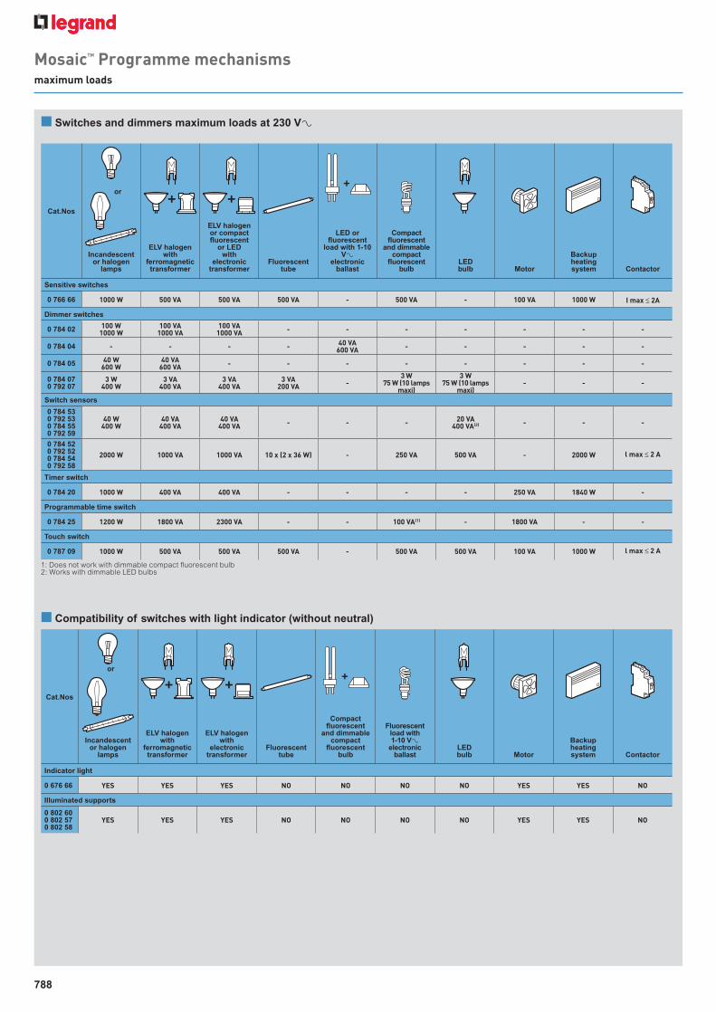
MosaicTM Programme mechanisms maximum loads
n Switches and dimmers maximum loads at 230 VA
n Compatibility of switches with light indicator (without neutral)
Cat.Nos
Incandescentor halogen
lamps
ELV halogenwith
ferromagnetictransformer
ELV halogenor compact fluorescent
or LEDwith
electronictransformer
Fluorescenttube
LED or fluorescent
load with 1-10 VA
electronicballast
Compactfluorescent
and dimmablecompact
fluorescentbulb
LEDbulb Motor
Backupheatingsystem Contactor
Sensitive switches
0 766 66 1000 W 500 VA 500 VA 500 VA - 500 VA - 100 VA 1000 W I max ≤ 2A
Dimmer switches
0 784 02 100 W1000 W
100 VA1000 VA
100 VA1000 VA - - - - - - -
0 784 04 - - - - 40 VA600 VA - - - - -
0 784 05 40 W600 W
40 VA600 VA - - - - - - - -
0 784 070 792 07
3 W400 W
3 VA400 VA
3 VA400 VA
3 VA200 VA -
3 W75 W (10 lamps
maxi)
3 W75 W (10 lamps
maxi)- - -
Switch sensors
0 784 530 792 530 784 550 792 59
40 W400 W
40 VA400 VA
40 VA400 VA - - - 20 VA
400 VA(2) - - -
0 784 520 792 520 784 540 792 58
2000 W 1000 VA 1000 VA 10 x (2 x 36 W) - 250 VA 500 VA - 2000 W l max ≤ 2 A
Timer switch
0 784 20 1000 W 400 VA 400 VA - - - - 250 VA 1840 W -
Programmable time switch
0 784 25 1200 W 1800 VA 2300 VA - - 100 VA(1) - 1800 VA - -
Touch switch
0 787 09 1000 W 500 VA 500 VA 500 VA - 500 VA 500 VA 100 VA 1000 W l max ≤ 2 A
Cat.Nos
Incandescentor halogen
lamps
ELV halogenwith
ferromagnetictransformer
ELV halogenwith
electronictransformer
Fluorescenttube
Compactfluorescent
and dimmablecompact
fluorescentbulb
Fluorescentload with 1-10 VA
electronicballast
LEDbulb Motor
Backupheatingsystem Contactor
Indicator light
0 676 66 YES YES YES NO NO NO NO YES YES NO
Illuminated supports
0 802 600 802 570 802 58
YES YES YES NO NO NO NO YES YES NO
1: Does not work with dimmable compact fluorescent bulb2: Works with dimmable LED bulbs
or
or
87045 LIMOGES CedexTelephone : 33 0 5 55 06 87 87 - Fax : 33 0 5 55 06 88 88
Cat. No(s): 784 05MosaicTM
Dimmer switch, 600 W
Technical sheet: F00483EN/01 Updated: 20/02/2009 Created: 14/11/2007
1/2
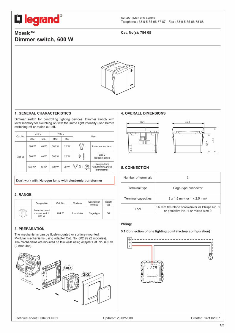
1. GENERAL CHARACTERISTICS
Dimmer switch for controlling lighting devices. Dimmer switch with level memory for switching on with the same light intensity used before switching off or mains cut-off.
2. RANGE
3. PREPARATION
The mechanisms can be flush-mounted or surface-mounted.Modular mechanisms using adapter Cat. No. 802 99 (2 modules).The mechanisms are mounted on thin walls using adapter Cat. No. 802 91 (2 modules).
4. OVERALL DIMENSIONS
5. CONNECTION
Wiring:
5.1 Connection of one lighting point (factory configuration)
Designation Cat. No. ModulesConnection
methodWeight
(g)
Remote-control dimmer switch
600 W784 05 2 modules Cage-type 56
40 mm min.
45.1 45.1
32.7 42
.9
Number of terminals 3
Terminal type Cage-type connector
Terminal capacities 2 x 1.5 mm2 or 1 x 2.5 mm2
Tool3.5 mm flat-blade screwdriver or Philips No. 1
or posidrive No. 1 or mixed size 0
< 2 s> 2 s
N
L
2 s
Don’t work with: Halogen lamp with electronic transformer
Cat. No.240 V 100 V
UseMax. Min. Max. Min.
784 05
600 W 40 W 300 W 20 W Incandescent lamp
600 W 40 W 300 W 20 W230 V
halogen lamps
600 VA 40 VA 300 VA 20 VAHalogen lamp
with ferromagnetic transformer
MosaicTM
Dimmer switch, 600 WCat. No(s): 784 05
Technical sheet: F00483EN/01 Updated: 20/02/2009 Created: 14/11/2007
2/2
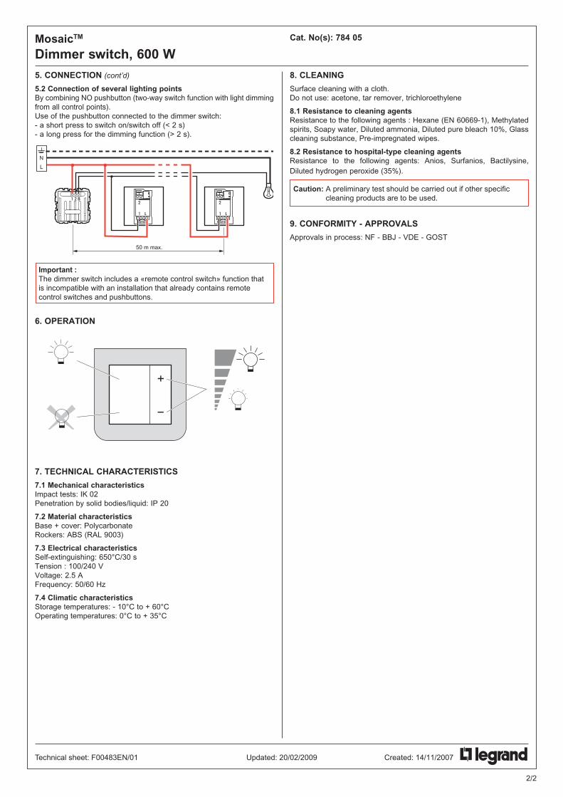
5. CONNECTION (cont’d)
5.2 Connection of several lighting points By combining NO pushbutton (two-way switch function with light dimming from all control points).Use of the pushbutton connected to the dimmer switch:- a short press to switch on/switch off (< 2 s)- a long press for the dimming function (> 2 s).
6. OPERATION
7. TECHNICAL CHARACTERISTICS
7.1 Mechanical characteristicsImpact tests: IK 02Penetration by solid bodies/liquid: IP 20
7.2 Material characteristicsBase + cover: Polycarbonate Rockers: ABS (RAL 9003)
7.3 Electrical characteristicsSelf-extinguishing: 650°C/30 s Tension : 100/240 V Voltage: 2.5 A Frequency: 50/60 Hz
7.4 Climatic characteristicsStorage temperatures: - 10°C to + 60°C Operating temperatures: 0°C to + 35°C
8. CLEANING
Surface cleaning with a cloth. Do not use: acetone, tar remover, trichloroethylene
8.1 Resistance to cleaning agentsResistance to the following agents : Hexane (EN 60669-1), Methylated spirits, Soapy water, Diluted ammonia, Diluted pure bleach 10%, Glass cleaning substance, Pre-impregnated wipes.
8.2 Resistance to hospital-type cleaning agentsResistance to the following agents: Anios, Surfanios, Bactilysine, Diluted hydrogen peroxide (35%).
9. CONFORMITY - APPROVALS
Approvals in process: NF - BBJ - VDE - GOST
< 2 s> 2 s
50 m max.
N
L
2 s
Important :The dimmer switch includes a «remote control switch» function that is incompatible with an installation that already contains remote control switches and pushbuttons.
Caution: A preliminary test should be carried out if other specific cleaning products are to be used.
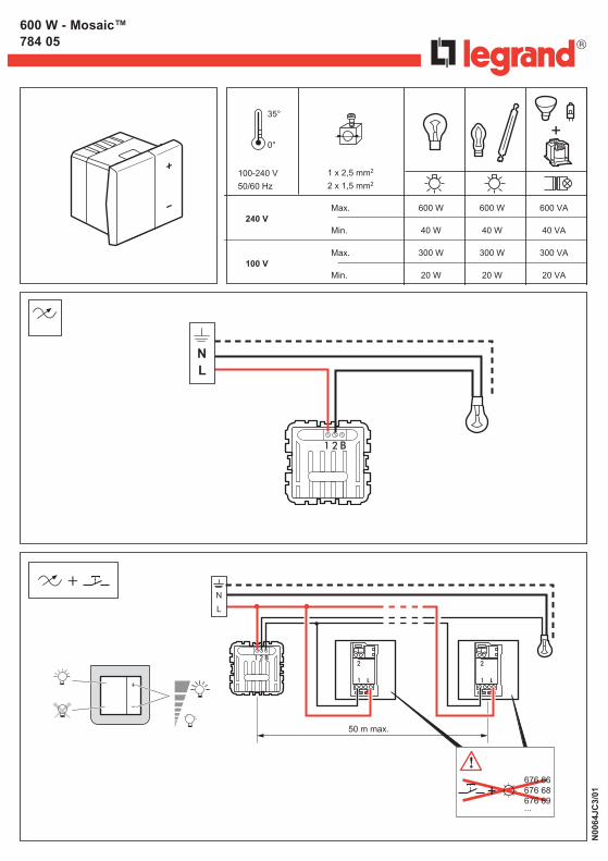
600 W - Mosaic™784 05
N00
64JC
3/01
35°
0°
100-240 V
50/60 Hz
1 x 2,5 mm2
2 x 1,5 mm2
Max.
Min.
Max.
Min.
600 W
40 W
300 W
20 W
600 W
40 W
300 W
20 W
600 VA
40 VA
300 VA
20 VA
240 V
100 V
N L
50 m max.
N
L
+676 66676 68676 69...
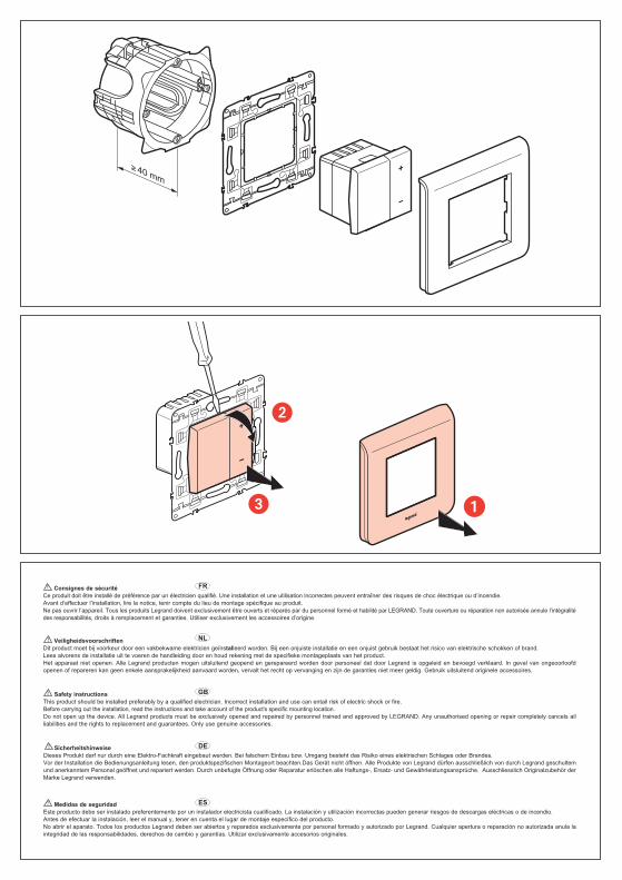
40 mm
VeiligheidsvoorschriftenDit product moet bij voorkeur door een vakbekwame elektricien geïnstalleerd worden. Bij een onjuiste installatie en een onjuist gebruik bestaat het risico van elektrische schokken of brand.Lees alvorens de installatie uit te voeren de handleiding door en houd rekening met de specifieke montageplaats van het product.Het apparaat niet openen. Alle Legrand producten mogen uitsluitend geopend en gerepareerd worden door personeel dat door Legrand is opgeleid en bevoegd verklaard. In geval van ongeoorloofdopenen of repareren kan geen enkele aansprakelijkheid aanvaard worden, vervalt het recht op vervanging en zijn de garanties niet meer geldig. Gebruik uitsluitend originele accessoires.
SicherheitshinweiseDieses Produkt darf nur durch eine Elektro-Fachkraft eingebaut werden. Bei falschem Einbau bzw. Umgang besteht das Risiko eines elektrischen Schlages oder Brandes. Vor der Installation die Bedienungsanleitung lesen, den produktspezifischen Montageort beachten.Das Gerät nicht öffnen. Alle Produkte von Legrand dürfen ausschließlich von durch Legrand geschultemund anerkanntem Personal geöffnet und repariert werden. Durch unbefugte Öffnung oder Reparatur erlöschen alle Haftungs-, Ersatz- und Gewährleistungsansprüche. Ausschliesslich Originalzubehör derMarke Legrand verwenden.
Safety instructionsThis product should be installed preferably by a qualified electrician. Incorrect installation and use can entail risk of electric shock or fire.Before carrying out the installation, read the instructions and take account of the product's specific mounting location.Do not open up the device. All Legrand products must be exclusively opened and repaired by personnel trained and approved by LEGRAND. Any unauthorised opening or repair completely cancels allliabilities and the rights to replacement and guarantees. Only use genuine accessories.
Medidas de seguridadEste producto debe ser instalado preferentemente por un instalador electricista cualificado. La instalación y utilización incorrectas pueden generar riesgos de descargas eléctricas o de incendio.Antes de efectuar la instalación, leer el manual y, tener en cuenta el lugar de montaje específico del producto.No abrir el aparato. Todos los productos Legrand deben ser abiertos y reparados exclusivamente por personal formado y autorizado por Legrand. Cualquier apertura o reparación no autorizada anula laintegridad de las responsabilidades, derechos de cambio y garantías. Utilizar exclusivamente accesorios originales.
ES
DE
GB
NL
Consignes de sécuritéCe produit doit être installé de préférence par un électricien qualifié. Une installation et une utilisation incorrectes peuvent entraîner des risques de choc électrique ou d’incendie.Avant d’effectuer l’installation, lire la notice, tenir compte du lieu de montage spécifique au produit.Ne pas ouvrir l’appareil. Tous les produits Legrand doivent exclusivement être ouverts et réparés par du personnel formé et habilité par LEGRAND. Toute ouverture ou réparation non autorisée annule l’intégralitédes responsabilités, droits à remplacement et garanties. Utiliser exclusivement les accessoires d’origine.
FR
��
�