Embed Size (px)
Citation preview

Moore Industries
CENTERProviding Instrumentation fastfrom our Quick-Ship Facilities!
STAR Center is Service, Technical Assistance and Repair.
If you need it today — It’s on its way!Call us TOLL FREE
United States1-800-999-2900
United Kingdom008 251928
• Signal Transmitters
• Temperature Transmitters
• I/P and P/I Converters
• Isolators and Converters
• Indicators and Displays
• Alarm Trips
• Integrators and Totalizers
• Power Transducers
• Instrument Power Supplies
• Racks, Rails and Enclosures
IN
STOCK
FAST
REPAIRS
TOO!
READY
TO
SHIP
CCS®
Page 1
The Interface Solution Experts
IntroductionMoore Industries’ Cable Concentrator System®, theCCS
®
, is an easy-to-use, highly cost-effective group ofdevices used to “concentrate” and transmit multipleprocess instrumentation signals from point to point.
According to the requirements of your application, theSystem may be configured to use a single twisted wirepair, modems, or fiber optics to link its communica-tions modules. This provides significant cost, mainte-nance, and space savings over bulky, conventionalmulti-conductor cabling.
This manual contains the information necessary to setjumpers, set system operating parameters, install,operate, maintain, and troubleshoot the CCS. It in-cludes a brief unit description, a table of performanceand operational specifications, and an explanation ofMoore Industries’ model number-based product datatracking system.
The following guidelines are used throughout themanual:
Warning – Hazardous procedure or condition thatcould injure or be fatal to the operator.
Caution – Hazardous procedure or condition that coulddamage or destroy the unit.
Note – Information that is essential for a procedure,condition, or operation of the unit.
Naming Conventions. In the remainder of thismanual, the UP and DOWN arrow pushbuttons arereferred to simply as UP and DOWN.
UP represents the membrane pushbutton,
and
DOWN represents the pushbutton.
Also, the “SELECT”, “ENTER”, and “ACK” push-but-tons are referred to as simply SELECT, ENTER, andACK.
In order to distinguish them from surrounding texts,references to readouts on the LCD will be made usinga special typeface. For example:
LCD READOUT
This font is not an exact replica of the actual LCD, butthe text accurately reflects the display on your mod-ules.
DescriptionThe Cable Concentrator System consists of an InputModule (IMM) and an Output Module (OMM).
The IMM collects and “concentrates” up to sixteeninputs, and transmits them as a single signal to theOMM. The OMM receives this signal from the IMM,then “separates” it and provides up to sixteen outputsin a customer-defined format.
Any IMM/OMM pair is capable of concentrating, trans-mitting, receiving, and separating up to sixteen inputsand outputs. By using a “daisy chain” serial connec-tion technique, up to eight units can be used on eitherend of a CCS link. This allows the user to accommo-date up to one-hundred and twenty-eight inputs andtheir respective outputs in a CCS system. Figure 1illustrates one type of daisy chain.

CCS®
Page 2
The Interface Solution Experts
As the figure shows, in a multi-module application, oneIMM must be configured as the System Master. Allother IMMs must be configured as “Slaves”. The set-ting of the Master/Slave operating parameter is de-scribed in the Communications Setup section of thismanual.
The CCS with the Modbus option allows the IMMs andOMMs to be connected independently to a DCS sys-tem in a peer-to-host arrangement. It uses ModbusRTU® protocol for communications. These units can-not be interchanged or combined with non-Modbusunits. Refer to the Specifications list and OrderingInformation Table for more information.
Data CommunicationsThe CCS can be ordered in either a peer-to-peer con-figuration, or with the –MBR option in a peer-to-hostsetup.
Communications in a peer-to-peer configuration use aRS-485 proprietary protocol. Peer-to-host CCS(-MBR option) use RS-485 with Modbus® RTU for com-munications between a PC or DCS and IMMs or OMMs.Refer to the Specifications list and Ordering Informa-tion Table, later in this manual, for more information onbaud rates, link length and the –MBR option.
Figure 1. Connecting the CCS in a “Daisy Chain” Application
Modbus RTU is a registered trademark of MODICON, Inc.,North Andover, MA 01845
IMM-1
IMM-2
IMM-3
IMM4
IMM-5
IMM-6
IMM-7
IMM-8
16 INPUTSANALOG/
DISCRETE
16 INPUTSANALOG/
DISCRETE
16 INPUTSANALOG/
DISCRETE
16 INPUTSANALOG/
DISCRETE
16 INPUTSANALOG/
DISCRETE
16 INPUTSANALOG/
DISCRETE
16 INPUTSANALOG/
DISCRETE
16 INPUTSANALOG/
DISCRETE
COMMLINK
FIE
LD D
EV
ICE
S
OMM-1
OMM-2
OMM-3
OMM-4
OMM-5
OMM-6
OMM-7
OMM-8
16 OUTPUTSANALOG/
DISCRETE
RE
AD
OU
T D
EV
ICE
S
SLA
VE
MASTER
16 OUTPUTSANALOG/
DISCRETE
16 OUTPUTSANALOG/
DISCRETE
16 OUTPUTSANALOG/
DISCRETE
16 OUTPUTSANALOG/
DISCRETE
16 OUTPUTSANALOG/
DISCRETE
16 OUTPUTSANALOG/
DISCRETE
16 OUTPUTSANALOG/
DISCRETE

CCS®
Page 3
The Interface Solution Experts
Special Compatibility NoteThis manual is intended for use with non-Modbus CCSmodules with module serial numbers 707795 andabove and Modbus units with version 1.0 firmware.
Operational and performance data in this manual maynot apply to Systems using earlier firmware releases.
The IMM and OMMCCS hardware modules are packaged in compact,aluminum DIN-style rail-mount housings. Refer to theInstallation section of this manual for the physical di-mensions of each housing style.
For applications requiring dust- or moisture-tight pro-tection, or corrosion resistance, enclosures areavailable. Contact your Moore Industries Sales Rep-resentative for more information.
The Discrete IMM. This type of module is configuredby the factory so that all of its sixteen channels acceptand process discrete inputs exclusively. The user canconfigure each channel to accept either contact clo-sure or transistor/transistor logic (TTL) inputs.
The Universal IMM. This type of module is capableof accepting and processing any combination of dis-crete or analog inputs. The user selects the type ofinput to be processed by each channel.
Analog-configured channels can be set to accept ei-ther current or voltage input. Discrete-configuredchannels, as in the Discrete version of the IMM, areselectable for either contact closure or TTL inputs.
The Discrete OMM. As in the Discrete IMM, thismodule is factory-set to process and output discretesignals exclusively. There are two types of DiscreteOMMs available.
One provides the user with the capability of configur-ing individual channels for either contact closure or TTLoutput. The other is set at the factory with contactclosure outputs exclusively. This second type can beordered with internal miniature power relays normallyopen or normally closed.
The Universal OMM. This type of module providesany user-selected combination of analog or discreteoutputs (miniature power relay output not available).
The Specification and Ordering Information tablescontain the operational and performance specificationsfor the CCS.
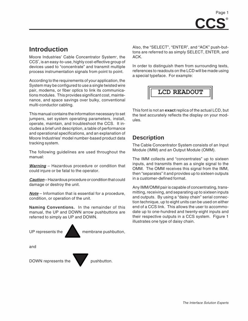
Figure 2 shows a generic front panel. On your System’sunits, the IMM or OMM designator appears in the upperleft corner of the panel.
CCS®
Page 4
The Interface Solution Experts
1 CH 1 CLOSED
24 VDC1 2 3 4 5 6 7 8 9 10 11 12 13 14 15 16
A B SLINK
A B SLINK
XMT RCV FAULT
ENTERSELECT
•PUTMODULE
CABLE CONCENTRATOR SYSTEMPATENT PENDING
•
®®
ACK
XMT RCV FAULT
ACK
24 VDC16A B S
LINKA B S
LINK
POWERHOOKUP
ACKNOWLEDGE ALARM,STOP FAULT LED FLASH,ACCESS ALARMS DISPLAY
FAULT LED,FLASHES TO INDICATELINK PROBLEM
LINK STATUSLEDS, INDICATE
SUCCESSFUL DATATRANSFER
LINKCONNECTIONS
FAULT CONTACTCONNECTION
Figure 2. CCS Modules’ Front Panel
CCS®
Page 5
The Interface Solution Experts
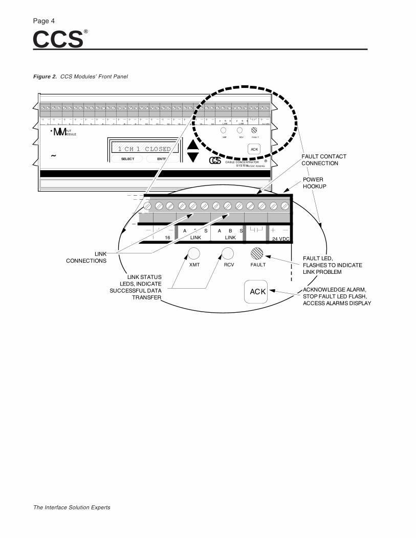
Ordering InformationUnit Input Output Power Options Housing
IMMInput Module (16channels permodule; 8 modulesper systemmaximum)OMMOutput Module (16channels permodule; 8 modulesper systemmaximum)
NOTE: For Peer-to-PeerSystems, IMM and OMMmodules must be orderedin pairs, with a maximumof eight pairs per system.
(See Table 1 for descriptions)
IMM INPUT MODULE:U 16 input channels configuredto accept any combination ofanalog and/or discrete signals;in Peer-to-Peer Systems, pairwith OMM with ÒUÓ outputtypeD 16 input channels acceptdiscrete signals; In Peer-to-PeerSystems, pair with OMM withÒRÓ or ÒTÓ output type
OMM OUTPUT MODULE:RS485 communication from amatching IMM module orcomputer-based host
(See Table 1 for descriptions)
IMM INPUT MODULE:RS485 to a matching OMM orcomputer-based host
OMM OUTPUT MODULE:U 16 output channelsconfigured to accept anycombination of analog and/ordiscrete signals; In Peer-to-PeerSystems, pair with IMM withÒUÓ input typeR 16 relay output channels(-NC or -NO option required)T 16 discrete output channelsdiscrete (contact closure)
18-30DC24Vdcnominal or24Vac,±10%,50/60Hz
NOTE: MooreIndustries DPS1200 and SMPPowerSupplies arerecommendedfor use withthe CCS. Askfor Datasheets11.1 and 11.3.
ÐMBRMODBUS RTUCommunicationlink for Peer-to-Host System (notavailable withPeer-to-PeerSystems)ÐNC Normallyclosed relays (R-type OMM only,see Table 1)ÐNO Normallyopen relays (R-type OMM only,See Table 1)
DIN AluminumDIN-style rail-mount housingmounts on32mm G-type(EN50035) and35mm Top Hat(EN50022) rails
(Single and multi-unitenclosures andcabinets available,call for details)
SpecificationsPerformance Calibration Capability:
±0.1% of maximum span foranalog input and ±0.1% ofmaximum span for analogoutputIsolation:IMM Input Module:Analog/TTL inputs isolatedto 175Vdc or ac peakbetween channels; 500Vacbetween inputs, power, anddata linkOMM Output Module:Analog outputs havecommon negative; discreteoutputs are isolated 500Vacbetween outputs/power/datalinkImpedance:IMM Voltage: 1M½IMM Current: 250½Drive Capability:OMM Analog: 0-20mA into0-850½; 0-10V outputlimited to 20mAOMM Discrete (OpenCollector): External power,42Vdc @ 100mASystem Fault Contact:120Vac @ 0.5A or 24Vdc @1A (non-inductive)Discrete OutputProtection:MOV protected on allcontact closure and relaychannels (discrete channelson Universal modules arenot protected)
COMM Link(Twisted
Wire Pair)
PowerSupply
Baud Rate: Any rate from 300through 19,200 is user-selectable.Modbus units: Any rate from 600through 19,200 is user-selectableCharacter FormatÐModbusUnits: Factory set, 1 start bit, 8data bits, 1 stop bit, no parityTransmission Range: Using24AWG twisted pair wiring,maximum of 2 miles (3.2km) @4800 baud or less; maximum of 1mile (1.6km) @ 9600 baud;maximum of 0.5 miles (0.8km) @19200 baud (modems andrepeaters are offered to increaseallowable transmission distances)Surge Protection: Order PartNumber 800-893-61 forcommunication link surgeprotector (see CCS Accessoriesfor details)
IMM Input Module (Currentconsumption @ 24Vdc,nominal):Analog Inputs: 175mADiscrete Inputs: 335mAMixed Inputs (Universal Module):335mA maximumOMM Output Module (currentconsumption @ 24Vdc,nominal):Analog Outputs: 500mADiscrete Outputs: 500mA with "R"output type, 335mA with "T" outputtypeMixed Outputs (Universal OMM):500mA
AmbientTemperature
Adjustments
Indicators
Weight
Operating Range: 0 to 65¡C (32 to 149¡F)Ambient TemperatureEffect: Less than±0.01%/¡C (analog inputsand outputs from 0 to65¡C)
Front PanelPushbuttons: Configureand calibrate modulechannels, configuremaster/slave, clearalarms, and activate/de-activate modem softwareInternal SolderlessJumpers: Configurechannels for analog(current or voltage) ordiscrete (contact closure)inputs/outputs
Integral Display:16 character LCD showsmodule identificationnumber, channel number,and process value duringconfiguration, calibration,and operationFront Panel LEDs:Indicate module istransmitting/receiving dataproperly, and when theunit is in a fault condition
2lbs., 14 oz. (1.3Kg) permodule
CCS®
Page 6
The Interface Solution Experts
Module TypeSignal
DirectionInput/Output Signal Possibilites
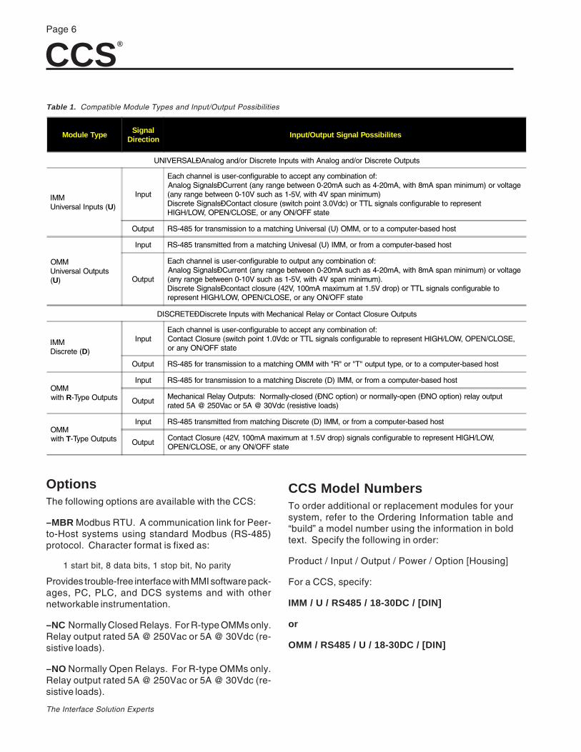
UNIVERSALÐAnalog and/or Discrete Inputs with Analog and/or Discrete Outputs
IMMUniversal Inputs (U)
Input
Each channel is user-configurable to accept any combination of:Analog SignalsÐCurrent (any range between 0-20mA such as 4-20mA, with 8mA span minimum) or voltage(any range between 0-10V such as 1-5V, with 4V span minimum)Discrete SignalsÐContact closure (switch point 3.0Vdc) or TTL signals configurable to representHIGH/LOW, OPEN/CLOSE, or any ON/OFF state
Output RS-485 for transmission to a matching Universal (U) OMM, or to a computer-based host
OMMUniversal Outputs(U)
Input RS-485 transmitted from a matching Univesal (U) IMM, or from a computer-based host
Output
Each channel is user-configurable to output any combination of:Analog SignalsÐCurrent (any range between 0-20mA such as 4-20mA, with 8mA span minimum) or voltage(any range between 0-10V such as 1-5V, with 4V span minimum).Discrete SignalsÐcontact closure (42V, 100mA maximum at 1.5V drop) or TTL signals configurable torepresent HIGH/LOW, OPEN/CLOSE, or any ON/OFF state
DISCRETEÐDiscrete Inputs with Mechanical Relay or Contact Closure Outputs
IMMDiscrete (D)
InputEach channel is user-configurable to accept any combination of:Contact Closure (switch point 1.0Vdc or TTL signals configurable to represent HIGH/LOW, OPEN/CLOSE,or any ON/OFF state
Output RS-485 for transmission to a matching OMM with "R" or "T" output type, or to a computer-based host
OMMwith R-Type Outputs
Input RS-485 for transmission to a matching Discrete (D) IMM, or from a computer-based host
OutputMechanical Relay Outputs: Normally-closed (ÐNC option) or normally-open (ÐNO option) relay outputrated 5A @ 250Vac or 5A @ 30Vdc (resistive loads)
OMMwith T-Type Outputs
Input RS-485 transmitted from matching Discrete (D) IMM, or from a computer-based host
OutputContact Closure (42V, 100mA maximum at 1.5V drop) signals configurable to represent HIGH/LOW,OPEN/CLOSE, or any ON/OFF state
Table 1. Compatible Module Types and Input/Output Possibilities
OptionsThe following options are available with the CCS:
–MBR Modbus RTU. A communication link for Peer-to-Host systems using standard Modbus (RS-485)protocol. Character format is fixed as:
1 start bit, 8 data bits, 1 stop bit, No parity
Provides trouble-free interface with MMI software pack-ages, PC, PLC, and DCS systems and with othernetworkable instrumentation.
–NC Normally Closed Relays. For R-type OMMs only.Relay output rated 5A @ 250Vac or 5A @ 30Vdc (re-sistive loads).
–NO Normally Open Relays. For R-type OMMs only.Relay output rated 5A @ 250Vac or 5A @ 30Vdc (re-sistive loads).
CCS Model NumbersTo order additional or replacement modules for yoursystem, refer to the Ordering Information table and“build” a model number using the information in boldtext. Specify the following in order:
Product / Input / Output / Power / Option [Housing]
For a CCS, specify:
IMM / U / RS485 / 18-30DC / [DIN]
or
OMM / RS485 / U / 18-30DC / [DIN]
CCS®
Page 7
The Interface Solution Experts
The CCS MenuThe CCS uses a simple hierarchical menu to set andcontrol both System-wide and individual module oper-ating parameters. The menu is displayed on modules’LCDs. The front panel membrane pushbuttons allowthe user to view and change the settings and status ofthe:
Communications Setup:MASTER/SLAVE (for IMMs only. Notavailable on MODBUS units )UNIT IDBAUD RATEandMODEM/NO MODEM (Not available onMODBUS units )
Configuration of Channels:(input for IMMs and output for OMMs)CONTACT CLOSURETTLVOLTAGEorCURRENT
Calibration of Channels:(relative to your application’s input andoutput)ZEROFULL SCALEINVERTED OUTPUTHIGH/OPEN or LOW/CLOSEDDEFAULT VALUEDEFAULT TO LAST VALUE (ENABLE/DISABLE)
Inverted output is possible with discrete-configuredchannels only. Zero and Full Scale input and outputsettings are available in Universal modules only. Volt-age and current are not available with discrete mod-ules configured by the factory.
AccessoriesThe link between IMM and OMM in a standard CCS isa single, RS-485 signal. This signal may be transmit-ted over a twisted wire pair for up to two miles, depend-ing upon the baud rate selected for use in your System(refer to specifications listing).
Incorporating Moore Industries Link Converter Mod-ule (LCM) or Link-to-Fiber Module (LFM) in the Sys-tem makes it possible, in some cases, to link modulesover greater distances using ordinary telephone linesor fiber optic communications cabling.
The following paragraphs comprise an overview ofthese, and other DIN-style accessories manufacturedby Moore Industries. See your Sales Representative,or contact Moore Industries for more information.
DIN-Style Power Supply, DPS-1200 – Solid-state,compact power supply with plug-in terminal connec-tors and snap-in mounting.
Link Converter Module, LCM – Compact unit forconverting the CCS’s RS-485 signal to standard RS-232C or RS-422 formats. Also available, Moore In-dustries’ Short Haul Modem (continuous link,non-switched), Dedicated Line Modem (leased lines),or Dial-up Modem (standard switched lines).
Two LCMs and two modems (up-link and down-link)are required for each CCS, if modem communicationsare desired (also requires MODEM configuration inSystem menu. See COMM SETUP section of thismanual).
Link-to-Fiber Module, LFM – DIN-style unit Con-verts the CCS’s RS-485 signal to communication-gradelight. If fiber-optic communications are required for yourapplication, two LFMs are required per CCS (up-linkand down-link).
Redundant Communication Link Module, RLM –Automatically switches the CCS signals to a second-ary link in the event of communications interruption onthe primary link. Two RLMs are required per CCS forup-link and down-link (can only be used in peer-to-peerconfigurations).
Supply Switching Module, SSM – Automaticallyswitches power supplies in the CCS in the event of afailure.

CCS®
Page 8
The Interface Solution Experts
DocumentationIncluded with each CCS, in addition to this User’sManual, you are shipped:
• A System Specification sheet
• Module Configuration Records (1 permodule)
• Module Configuration Record quick-reference Cards (also 1 per module)
The System Specification sheet documents how indi-vidual modules were configured within your CCS. TheModule Configuration Record lists the configuration ofeach channel in a given module. Both reference sheetslist the modules in your system by serial number, andmay be used to identify and keep track of, for example,which IMM is the Master, or which OMMs are config-ured for converting or inverting output values.
The Module Configuration quick-reference card is alsointended to function as an aid in keeping track ofchanges made to a Module’s operating parameters.Grease pencil or erasable marker can be used to noteoperating parameter selections or changes, and thecard may be stored in the compartment that comprisesthe unit’s bottom panel.
Setting ConfigurationJumpers/Bench CheckPrior to shipment, every CCS is subjected to rigoroustesting by our team of skilled technicians. Every prod-uct Moore Industries manufactures, sells and servicesis guaranteed to meet the strict quality standards thathave become synonymous with our name.
Before placing your CCS into service, a bench checkof basic operation is recommended to ensure that theunit hasn’t sustained any damage during transit.
Even if a unit has been configured to your specifica-tions by the factory (factory calibration), it is a goodidea to perform a simple bench check. The proce-dures provide a safe means to uncover any unit dam-age that may have occurred during shipping, and offersa familiarization with CCS operation in the safety of atesting environment, separate from the intended pro-cess or application.
Configuration Jumpers.The settings of jumpers on pc board 3 (PC3-See figure3) in each IMM or OMM determine the type of signalthat each of its channels will process, and the condi-tion (NO or NC) of its fault relay contacts.
Moore Industries records these jumper-dependentoperational characteristics on the Module Configura-tion Record, and packs a copy of this record inside thestorage compartment of each module.
The following sections describe the procedures fordisassembling CCS modules and setting the jumpersthat control channel configuration and fault relay con-tacts.
Before going on, check the Module ConfigurationRecord of each of the modules in your System. If theconfiguration of the channels, and the fault contactcondition on the IMMs and OMMs are correct, themodule need not be disassembled. Skip to the BenchCheck section of this manual.

CCS®
Page 9
The Interface Solution Experts
Figure 3. Disassembling the CCS Modules
NOTE:It is strongly recommended that a modulebe bench checked whenever any jumpers
are moved.
Module Disassembly. To verify or change the posi-tion of the CCS module configuration jumpers, the toppanel of the module housing must be removed. All ofthe customer-set jumpers in the CCS modules arelocated on PC board 3 (PC3).
It is recommended that the procedures in these sec-tions be performed at a technician’s bench or in a simi-lar laboratory setting. To complete the procedures, youwill need a small Phillips-head screwdriver and a pairof narrow, needle-nose pliers.
Figure 3 illustrates the disassembly of CCS modules,and the location of PC3. The style of housing employedby discrete OMMs equipped with miniature power re-lays is slightly different than the one depicted, but re-gardless of which style housing is being disassembled,the two top-most screws on each side panel must beremoved.
CAUTION:Remove any power connection before
disassembly.Electrostatic discharge can permanently
damage the module.
TOP PANEL
FRONT PANEL
PC-3
CABLE CONCENTRATOR
SYSTEM
÷
SCREWS(TYPICAL)

CCS®
Page 10
The Interface Solution Experts
For Universal IMM Install Jumper(s)
Voltage NONE (store all jumpers)
Current A
TTL NONE (store all jumpers)
Contact closure B, C, D
For Discrete IMM Install Jumper(s)
TTL NONE (store all jumpers)
Dry Contact Closure C, D
Externally PoweredContact Closure
D
Setting IMM Configuration JumpersThere are sixteen sets of labeled jumpers on PC3 ofthe IMM. Each set (four jumpers per set) correspondsto a channel in the IMM, and the sets are numbered J1through J16. The J1 jumper controls channel 1, J2controls channel 2, etc.
Figure 4 shows the first four sets of jumpers on theboard as they will appear when the unit is orientedupright with the LCD facing the operator. The posi-tions of the jumpers are designated as “A”, “B”, “C”,and “D”.
Refer to Table 2 to determine the configuration of eachIMM channel as required by your application, and usefigure 4 to set the jumpers. If a jumper is not set, itshould be stored on one pin only.
Figure 4. Setting IMM Configuration Jumpers
Table 2. Positioning IMM Configuration Jumpers
FRONT OF MODULE
LEFTSIDE
OF MODULE
J1 J2 J3 J4
VOLTAGEINPUTS
CURRENTINPUTS
(ALLSTORED)
(ALLSTORED)
TTLINPUTS
(UNIVERSAL IMM)
DCB
(A STORED)
DC
(A STORED)(NOT USED)
A
(D STORED)(C STORED)(B STORED)
CONTACTCLOSURE
INPUTS(UNIVERSAL
IMM)
CONTACTCLOSURE
INPUTS(DISCRETE
IMM)
TTLINPUTS
(DISCRETE IMM)
(NOT USED)(A STORED)
(D STORED)(C STORED)
D(C STORED)B
(A STORED)
EXTERNALLY POWEREDCONTACT CLOSURE
INPUTS (ALL IMM TYPES)

CCS®
Page 11
The Interface Solution Experts
Desired OMM Output Install Jumpers
Voltage B, C, D, F
Current A, C, F
Contact Closure A, E
TTL A, E, H
Setting Fault ContactConfiguration JumpersAll IMMs and OMMs are equipped with a fault relay.The output of the relay is accessible at the Fault Con-tact terminals on the front panel, and the setting of oneinternal jumper on PC3 determines how the relay con-tacts will operate.
Table 3. Positioning OMM Configuration Jumpers
Figure 5. Positioning OMM Configuration Jumpers
Setting OMM Configuration JumpersSixteen sets of OMM configuration jumpers are locatedon PC3. The jumper sets are not labeled on the OMMboard, but with the module front panel upright andfacing the operator, the left-most set corresponds tochannel 1 and the right-most set corresponds to chan-nel 16.
Figure 5 shows the first six sets of jumpers, and illus-trates the positioning required for the various outputconfigurations. Table 3 summarizes the installation.Unused jumpers can be stored on one pin.
NOTE:Discrete OMMs configured by the factory
for relay output do not use customer-selectable jumpers for channel
configuration.
Refer to the Specifications listing for dataon the output of the Discrete OMM.
(Stored)
VOLTAGEOUTPUT
B
F
CD
A
F
C
CURRENTOUTPUT
TTLOUTPUT
AE
H
(Stored)
CONTACTCLOSUREOUTPUT
A
E
(Stored)
(Stored)
CH
AN
NE
L 6
CH
AN
NE
L 1
CH
AN
NE
L 2
CH
AN
NE
L 3
CH
AN
NE
L 4
CH
AN
NE
L 5
FRONT OF MODULE
LEFTSIDEOF MODULE

CCS®
Page 12
The Interface Solution Experts
Module TypeDesired Fault RelayContact Operation
Install
IMM
OPENS in alarm orpower loss
J201
CLOSES in alarm orpower loss
J202
OMM
Closes in alarm or powerloss
J200
OPENS in alarm orpower loss
J201
DISCRETE OMMConfigured for
RELAY OUTPUT
OPENS in alarm orpower loss
J172
CLOSES in alarm orpower loss
J171
J172
J171
PC3 INDISCRETE OMM’sEQUIPPED W ITHRELAY OUTPUT(ROMM/TOMM)
RIGHT END OFFRONT PANEL
J201
J200
RIGHT END OFFRONT PANEL
J201
J202
PC3 INIMM
RIGHT END OFFRONT PANEL
PC 3 IN OMM
With the module front panel upright and facing theoperator, the jumper can be found on the front, right-most corner of the board.
Figure 6 shows the location of the Fault Contact Con-figuration jumper on PC3 of all three types of IMM andOMM.
Use Figure 6 and Table 4 to set the jumper for OPENor CLOSED in the event of a link problem or powerloss.
Table 4. Positioning Fault Contact Jumper
Figure 6. Positioning the CCS Modules’ Fault ContactConfiguration Jumpers

CCS®
Page 13
The Interface Solution Experts
Equipment Specifications
Signal Source Universal Modules: Capable of Voltage andCurrent output, accurate to within 0.01% ofspanDiscrete Modules: ON/OFF switch or similardevice
DigitalMultimeter
Fluke Model 8060 or equivalent; accurate towithin 0.01% of span
PowerSupplies (2)
Contact Closure-configured IMMs and OMMs:335mATTL-configured IMMs: 175mATTL-configured Discrete OMMs: 335mAUniversal IMMs: 335mAUniversal OMMs: 500mARTOMMs: 450mA
Screwdrivers Small Philips-headandSlotted type with head width no greater than2.54 mm (0.1 in)
Bench Check–Non-Modbus UnitsThis section provides the instructions for a simple testof the basic operation of the modules in your CCS. ForCCS systems using Modbus, refer to the Bench Checksection for Modbus units. With the Bench Check, theuser may verify operating levels and channel configu-ration settings, and become familiar with the basicconnection and operating techniques of the CCS in acontrolled environment, isolated from any actual appli-cation.
The equipment listed in Table 5 is needed when benchchecking the CCS. These items are not supplied byMoore Industries, but should be available in most test-ing labs.
Special Considerations – The IMM as Master orSlave. In Systems with only one IMM/OMM pair, thesetting for the IMM must be Master. In multi-IMMSystems, one IMM must be configured as a Master andall others as Slaves. Modbus units cannot be config-ured as Masters or Slaves.
Accordingly, the factory default setting in single-IMMSystems is “Master”. In multi-IMM Systems, the Sys-tem Specification sheet identifies the Master IMM.
Earlier versions of the CCS IMM used a jumper to controlthe unit’s functioning as a MASTER or SLAVE. TheSystem described in this manual uses the SystemMenu to control this operating parameter. The proce-dure for setting Master/Slave is outlined in the COMMSETUP section of this manual.
The Bench Check Procedure contains the instructionsfor connecting and bench checking a Slave IMM.
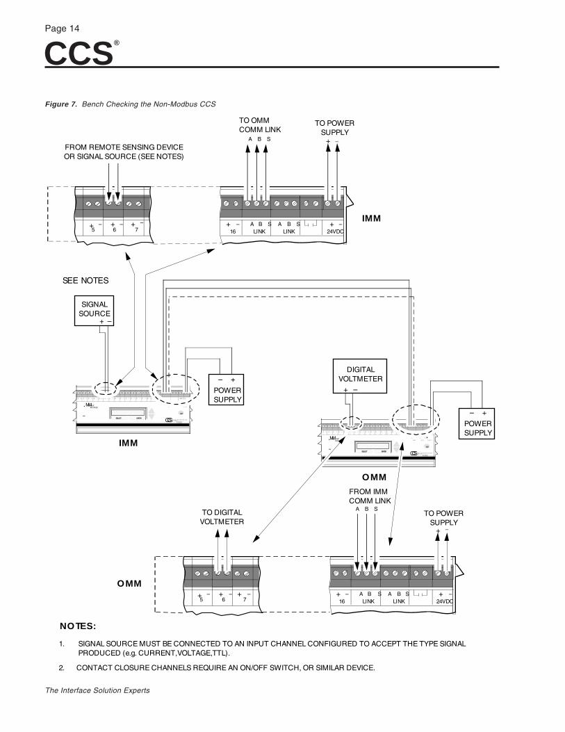
Figure 7 shows the Bench Check setup for non-Modbusunits. It depicts the connection of a Master IMM to anOMM. If you have a multiple-IMM CCS, use the Sys-tem Specification sheet to select the Master IMM.
CAUTION:Always make sure components and tools
are properly safeguarded againstaccidental electrostatic discharge.
To Setup for the Benchcheck:
Table 5. CCS Bench Check Equipment
CCS®
Page 14
The Interface Solution Experts
Figure 7. Bench Checking the Non-Modbus CCS
SIGNAL SOURCE MUST BE CONNECTED TO AN INPUT CHANNEL CONFIGURED TO ACCEPT THE TYPE SIGNALPRODUCED (e.g. CURRENT,VOLTAGE,TTL).
NOTES:
1.
2. CONTACT CLOSURE CHANNELS REQUIRE AN ON/OFF SWITCH, OR SIMILAR DEVICE.
IMM
+ –65 7
OMM
+ –24VDC+ –
16 LINK LINKA B S A B S
A B S
FROM IMMCOMM LINK
FROM REMOTE SENSING DEVICEOR SIGNAL SOURCE (SEE NOTES)
+ – + –
+ –65 7
+ – + –
+ –24VDC+ –
16 LINK LINKA B S A B S
A B S
TO OMMCOMM LINK
TO POWERSUPPLY
+ –
IMM
OMM
TO POWERSUPPLY
+ –
TO DIGITALVOLTMETER
POWERSUPPLY
+–
A B S A B S
X M T R C V F A U L T
ENTERSELECT
• PUTM O DULE•
ACK
P A T E N T P E N D IN G
C A B L E C O N C E N T R A T O R S Y S T E M
+ –
SIGNAL SOURCE
POWERSUPPLY
+–
1 2
A B S A B S
X M T R C V F A U L T
ENTERSELECT
•
ACK
P A T E N T P E N D IN G
C A B L E C O N C E N T R A T O R S Y S T E M
+ –
DIGITALVOLTMETER
• PUTM O DULE
SEE NOTES
CCS®
Page 15
The Interface Solution Experts
I I
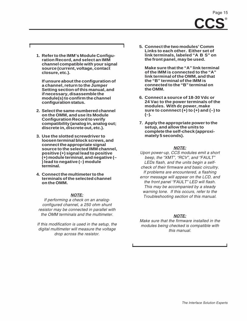
1. Refer to the IMM’s Module Configu-ration Record, and select an IMMchannel compatible with your signalsource (current, voltage, contactclosure, etc.).
If unsure about the configuration ofa channel, return to the JumperSetting section of this manual, andif necessary, disassemble themodule(s) to confirm the channelconfiguration status.
2. Select the same-numbered channelon the OMM, and use its ModuleConfiguration Record to verifycompatibility (analog in, analog out;discrete in, discrete out, etc.).
3. Use the slotted screwdriver toloosen terminal block screws, andconnect the appropriate signalsource to the selected IMM channel,positive (+) signal lead to positive(+) module terminal, and negative (–) lead to negative (–) moduleterminal.
4. Connect the multimeter to theterminals of the selected channelon the OMM.
NOTE:If performing a check on an analog-
configured channel, a 250 ohm shuntresistor may be connected in parallel with
the OMM terminals and the multimeter.
If this modification is used in the setup, thedigital multimeter will measure the voltage
drop across the resistor.
5. Connect the two modules’ CommLinks to each other. Either set oflink terminals, labeled “A B S” onthe front panel, may be used.
Make sure that the “A” link terminalof the IMM is connected to the “A”link terminal of the OMM, and thatthe “B” terminal of the IMM isconnected to the “B” terminal onthe OMM.
6. Connect a source of 18-30 Vdc or24 Vac to the power terminals of themodules. With dc power, makesure to connnect (+) to (+) and (–) to(–).
7. Apply the appropriate power to thesetup, and allow the units tocomplete the self-check (approxi-mately 5 seconds).
NOTE:Upon power-up, CCS modules emit a short
beep, the “XMT”, “RCV”, and “FAULT”LEDs flash, and the units begin a self-
check of their firmware and basic circuitry.If problems are encountered, a flashing
error message will appear on the LCD, andthe front panel “FAULT” LED will flash.This may be accompanied by a steady
warning tone. If this occurs, refer to theTroubleshooting section of this manual.
NOTE:Make sure that the firmware installed in themodules being checked is compatible with
this manual.
I I

CCS®
Page 16
The Interface Solution Experts
When power is applied to modules in the CCS, the firstreadout to appear on the LCD is the Module Type/Version Display. This display shows the version of thefirmware installed in the module.
To Bench check the CCS:
I I
1. Verify that the Channel StatusDisplay appears on the LCDs of theIMM and OMM being checked. Thefollowing is an example of aChannel Status Display:
1 CH 1 CLOSED
1 = The Module ID Number. 1-8 are possible.
CH 1 = The Channel Number. 1-16 are possible.
CLOSED = The Status of the channel being dis-played; closed, open, high, low, or a value that rep-resents a percentage of span.
2. Supply the signal to the IMM.
3. Press UP or DOWN on the IMM untilthe channel being checked isdisplayed on the LCD.
4. Press UP or DOWN on the OMMuntil the channel being checked isdisplayed on the LCD.
5. Observe the display on bothmodules, and use the multimeterand Module Configuration Recordsto verify that the type of signal atthe OMM terminals is appropriatefor the input on the IMM.
For example, analog input at theIMM should output as analogsignals on the OMM, ContactClosure “in” should produceContact Closure “out”, etc.
Module operations unaffected byinternal jumper positioning, such asinverted, scaled, or convertedoutputs, should be verified on theModule Configuration Record. Theprocedure for changing thesesettings will be discussed later inthis manual.
6. When these channels have beenbench checked, choose another pairof channels and repeat steps 1- 5until all channels are checked.
I I
To Bench Check Slave IMMs in a multi-module(“Daisy-Chained”) CCS, complete the procedure for theMaster IMM and its paired OMM first, then:
I I
1. Start with the setup depicted inFigure 7, with the Master IMM and itspaired OMM, then choose a slaveIMM and its paired OMM.
2. Connect the link terminals on theSlave IMM to the matching set on itspaired OMM; “A” to “A”, “B” to “B”,and “S” to “S”.
3. Connect the second set of OMM linkterminals to the remaining set of linkterminals on either the Master IMM ortiits paired OMM.
4. Connect a source of 18-30 Vdc or 24Vac to the power terminals of theSlave IMM and its OMM. If using dcpower, connect (+) to (+) and (–) to (–). Do not apply power to the setup atthis time.
5. Go to Step 2 of the Bench Check andperform the IMM operation on theSlave IMM. Where the instructionscall for an OMM, use the OMM that ispaired with the Slave IMM.
NOTE:During bench check, the “XMT” and “RCV”LEDs on the IMM and OMM will flash. This
indicates a data transfer.
I I

CCS®
Page 17
The Interface Solution Experts
Bench Check ExampleThe Module Configuration Record for a Master IMM
lists its Module ID number as 1, and channel 5 asconfigured for Contact Closure input.
A field device that supplies a dry Contact Closure sig-nal (>300 ohms open and <100 ohms closed) is con-nected to channel 5 of this IMM.
The Module Configuration Record for OMM #1 in thisSystem shows that it is factory-configured as a discreteOMM, and that it is equipped with the Normally OpenOption of the miniature power relay outputs (ROMM, -NO).
These modules are connected as described in theBench Check Setup. After appropriate power is ap-plied to both units and the firmware’s self-check iscompleted, the contact in the signal source is opened.
DOWN is pressed on both modules until the fol-lowing is displayed on the IMM:
1 CH 5 OPEN
And this appears on the LCD of the OMM:
1 CH 5 OPEN
The meter shows infinite (>300) ohms resistance.
When the signal source contacts are closed, the IMMwill display changes appropriately, and the OMM alsowill display the change in relay state. The multimeterindicates negligible (<100 ohms) resistance.
Bench Check–Modbus UnitsThis section provides the instructions for a simple testof the basic operation of the modules in your CCS. Withthe Bench Check, the user may verify operating levelsand channel configuration settings, and become fa-miliar with the basic connection and operating tech-niques of the CCS in a controlled environment, isolatedfrom any actual application.
This section is for CCS units equipped with Modbus.If your unit does not have the Modbus option, refer tothe bench check section for non-Modbus units earlierin this manual.
Figure 8 shows the Bench Check setup for Modbusunits. It depicts the connection of IMMs and OMMs toa PC. The IMMs and OMMs may be connected to thePC simultaneously during bench check, however onlyone module can be bench checked at a time.
CAUTION:Always make sure components and tools
are properly safeguarded againstaccidental electrostatic discharge.
NOTE:Make sure that the firmware installed in themodules being checked is compatible with
this manual.

CCS®
Page 18
The Interface Solution Experts
When power is applied to modules in the CCS, the firstreadout to appear on the LCD is the Module Type/Version Display. This display shows the version of thefirmware installed in the module.
To Bench Check the CCS:
I I
1. Connect the module(s) Comm linksto the PC. The “A” link terminalconnects to +Data (“A”, if using aconverter) and the “B” link terminalconnects to –Data (“B” , if using aconverter).
2. Connect a source of 18-30Vdc or24Vac to the power terminals of themodule(s). With dc power, makesure to connect (+) to (+) and (–) to(–).
3. Verify that the Channel StatusDisplay appears on the LCDs of theIMM and OMM being checked. Thefollowing is an example of aChannel Status Display:
1 CH 1 CLOSED
1 = The Module ID Number. 1-99 are possible.
CH 1 = The Channel Number. 1-16 are possible.
Figure 8. Bench Checking the Modbus-equipped CCS
CONVERTER(IF NEEDED)
UP TO 32 UNITS
RS232 RS485
CONNECT A TO +DATACONNECT B TO –DATA
+ DATA–DATA
24VDCPOWERSUPPLY
24VDCPOWERSUPPLY
+– +–
+–24VDC
POWERSUPPLY
+–24 VDCPOWERSUPPLY
FIELD DEVICES FIELD DEVICES
FIELD DEVICESFIELD DEVICES
X M T R C V F A U L T
ENTERSELECT
I NPUTM O DULE
ACK
P A T E N T P E N D IN G
C A B L E C O N C E N T R A T O R S Y S T E M
A B S A B S + –
X M T R C V F A U L T
ENTERSELECT
O UTPUTM O DULE
ACK
P A T E N T P E N D IN G
C A B L E C O N C E N T R A T O R S Y S T E M
A B S A B S
X M T R C V F A U L T
ENTERSELECT
I NPUTM O DULE
ACK
P A T E N T P E N D IN G
C A B L E C O N C E N T R A T O R S Y S T E M
A B S A B S
X M T R C V F A U L T
ENTERSELECT
O UTPUTM O DULE
ACK
P A T E N T P E N D IN G
C A B L E C O N C E N T R A T O R S Y S T E M
A B S A B S
IMM OMM
IMMIMM
CCS®
Page 19
The Interface Solution Experts
CLOSED = The Status of the channel being displayed;closed, open, high, low, or a value that represents apercentage of span.
4. Execute a Report Slave ID (Com-mand 17 or 11 HEX).
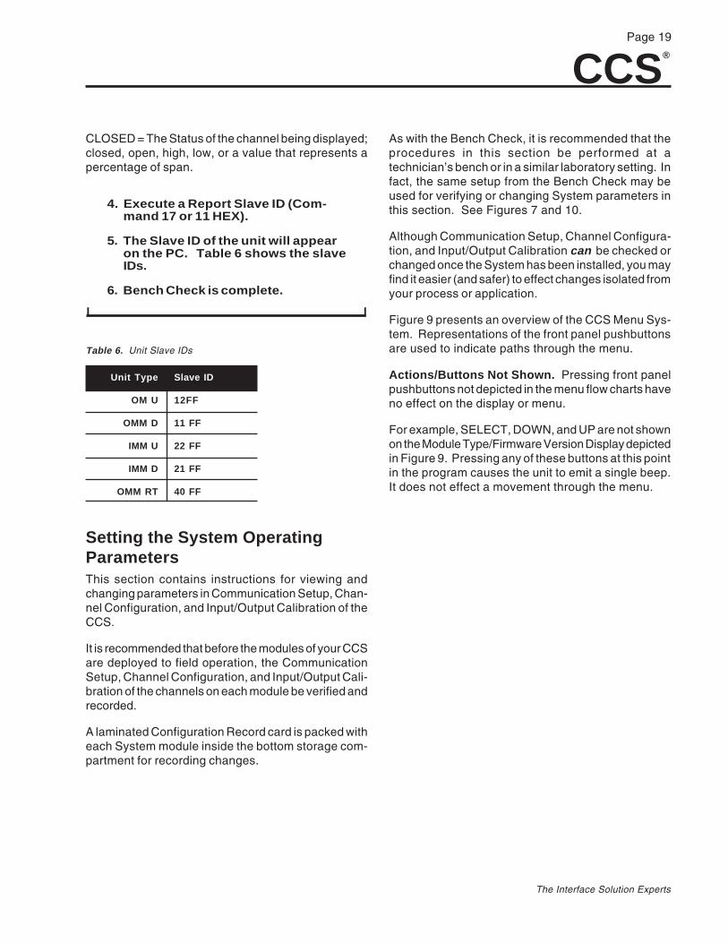
5. The Slave ID of the unit will appearon the PC. Table 6 shows the slaveIDs.
6. Bench Check is complete.
I I
As with the Bench Check, it is recommended that theprocedures in this section be performed at atechnician’s bench or in a similar laboratory setting. Infact, the same setup from the Bench Check may beused for verifying or changing System parameters inthis section. See Figures 7 and 10.
Although Communication Setup, Channel Configura-tion, and Input/Output Calibration can be checked orchanged once the System has been installed, you mayfind it easier (and safer) to effect changes isolated fromyour process or application.
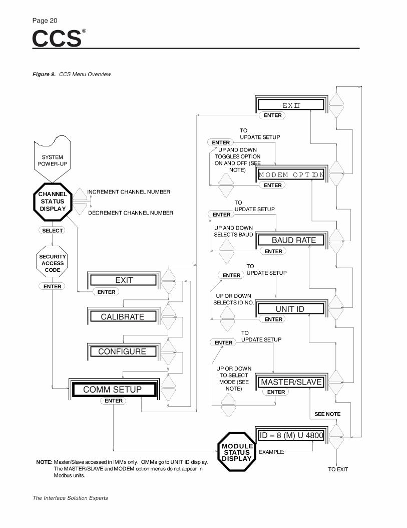
Figure 9 presents an overview of the CCS Menu Sys-tem. Representations of the front panel pushbuttonsare used to indicate paths through the menu.
Actions/Buttons Not Shown. Pressing front panelpushbuttons not depicted in the menu flow charts haveno effect on the display or menu.
For example, SELECT, DOWN, and UP are not shownon the Module Type/Firmware Version Display depictedin Figure 9. Pressing any of these buttons at this pointin the program causes the unit to emit a single beep.It does not effect a movement through the menu.
Table 6. Unit Slave IDs
Setting the System OperatingParametersThis section contains instructions for viewing andchanging parameters in Communication Setup, Chan-nel Configuration, and Input/Output Calibration of theCCS.
It is recommended that before the modules of your CCSare deployed to field operation, the CommunicationSetup, Channel Configuration, and Input/Output Cali-bration of the channels on each module be verified andrecorded.
A laminated Configuration Record card is packed witheach System module inside the bottom storage com-partment for recording changes.
Unit Type
OM U
OMM D
IMM U
IMM D
OMM RT
Slave ID
12FF
11 FF
22 FF
21 FF
40 FF
CCS®
Page 20
The Interface Solution Experts
Figure 9. CCS Menu Overview
INCREMENT CHANNEL NUMBER
DECREMENT CHANNEL NUMBER
MODULESTATUS
DISPLAY
M O D EM O P T IO N
EXIT
SYSTEMPOWER-UP
CHANNELSTATUSDISPLAY
SECURITYACCESS
CODE
EXAMPLE:
TO EXIT
UP OR DOWN TO SELECTMODE (SEE
NOTE)
TOUPDATE SETUP
UP OR DOWN SELECTS ID NO.
TOUPDATE SETUP
UP AND DOWN SELECTS BAUD
TOUPDATE SETUP
UP AND DOWN TOGGLES OPTIONON AND OFF (SEE
NOTE)
TOUPDATE SETUP
ENTER
SELECT
ENTER
ENTER
ENTER
ENTER
ENTER
ENTER
ENTER
ENTER
ENTER
ENTER
ENTER
SEE NOTE
NOTE: Master/Slave accessed in IMMs only. OMMs go to UNIT ID display.The MASTER/SLAVE and MODEM option menus do not appear in Modbus units.
EXIT
CALIBRATE
CONFIGURE
COMM SETUP
BAUD RATE
UNIT ID
MASTER/SLAVE
ID = 8 (M) U 4800
CCS®
Page 21
The Interface Solution Experts
SLAVE IMM #2
PAIRED OMM #2
POWERSUPPLY
+–
+ –
SIGNAL SOURCE
X M T R C V F A U L T
ENTERSELECT
• PUTM O DULE•
ACK
P A T E N T P E N D IN G
C A B L E C O N C E N T R A T O R S Y S T E M
A B SA B S
POWERSUPPLY
+–
1 2
X M T R C V F A U L T
ENTERSELECT
•
ACK
P A T E N T P E N D IN G
C A B L E C O N C E N T R A T O R S Y S T E M
+ –
DIGITALVOLTMETER
• PUTM O DULE
A B S A B S
PAIRED OMM#1
IMM #1(MASTER)
SEE FIGURE 7
From the Module Type/Firmware Version Display,ENTER is the only pushbutton that will permit accessany other point in the menu.
Special ACK Functions. During normal operation andwhile viewing or changing operating parameters, the“FAULT” LED on the front panel will begin to flash toindicate a problem with the link. If the firmware is at theChannel Status Display point in the menu, pressingACK accesses the Fault Status portion of the SystemMenu.
Pressing ACK at any other point in the menu will stopthe “FAULT” indicator’s flashing; causing it instead toglow steadily.
Also, from the Security Access Code display, pressingACK then ENTER before entering the correct codewill bring up the Fault Status portion of the SystemMenu.
Units with MBR option. Every IMM and OMM Chan-nel will have a register (one word) associated with it.The IMM has input registers and the OMM has holdingregisters. These registers will be addressed 0-15 forchannels 1-16 respectively.
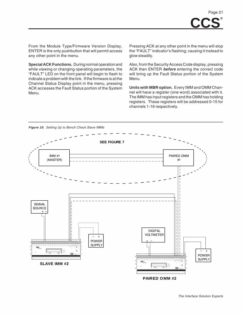
Figure 10. Setting Up to Bench Check Slave IMMs
CCS®
Page 22
The Interface Solution Experts
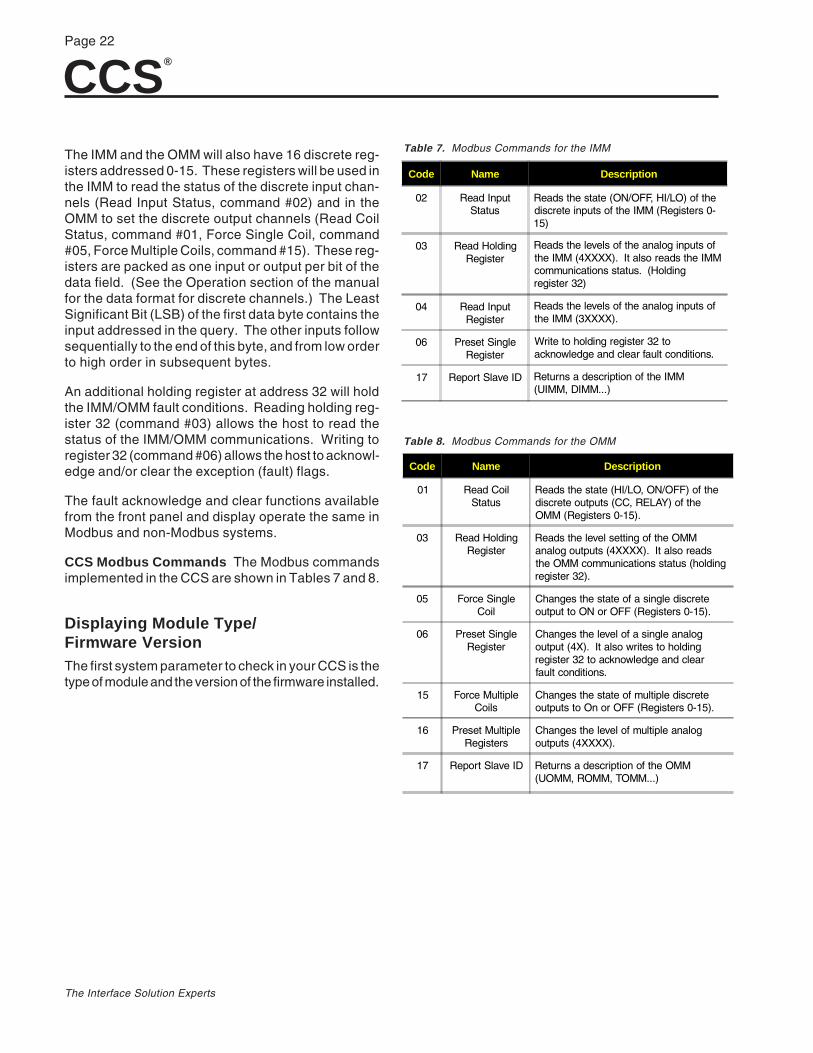
Code Name Description
01 Read CoilStatus
Reads the state (HI/LO, ON/OFF) of thediscrete outputs (CC, RELAY) of theOMM (Registers 0-15).
03 Read HoldingRegister
Reads the level setting of the OMManalog outputs (4XXXX). It also readsthe OMM communications status (holdingregister 32).
05 Force SingleCoil
Changes the state of a single discreteoutput to ON or OFF (Registers 0-15).
06 Preset SingleRegister
Changes the level of a single analogoutput (4X). It also writes to holdingregister 32 to acknowledge and clearfault conditions.
15 Force MultipleCoils
Changes the state of multiple discreteoutputs to On or OFF (Registers 0-15).
16 Preset MultipleRegisters
Changes the level of multiple analogoutputs (4XXXX).
17 Report Slave ID Returns a description of the OMM(UOMM, ROMM, TOMM...)
Code Name Description
02 Read InputStatus
Reads the state (ON/OFF, HI/LO) of thediscrete inputs of the IMM (Registers 0-15)
03 Read HoldingRegister
Reads the levels of the analog inputs ofthe IMM (4XXXX). It also reads the IMMcommunications status. (Holdingregister 32)
04 Read InputRegister
Reads the levels of the analog inputs ofthe IMM (3XXXX).
06 Preset SingleRegister
Write to holding register 32 toacknowledge and clear fault conditions.
17 Report Slave ID Returns a description of the IMM(UIMM, DIMM...)
The IMM and the OMM will also have 16 discrete reg-isters addressed 0-15. These registers will be used inthe IMM to read the status of the discrete input chan-nels (Read Input Status, command #02) and in theOMM to set the discrete output channels (Read CoilStatus, command #01, Force Single Coil, command#05, Force Multiple Coils, command #15). These reg-isters are packed as one input or output per bit of thedata field. (See the Operation section of the manualfor the data format for discrete channels.) The LeastSignificant Bit (LSB) of the first data byte contains theinput addressed in the query. The other inputs followsequentially to the end of this byte, and from low orderto high order in subsequent bytes.
An additional holding register at address 32 will holdthe IMM/OMM fault conditions. Reading holding reg-ister 32 (command #03) allows the host to read thestatus of the IMM/OMM communications. Writing toregister 32 (command #06) allows the host to acknowl-edge and/or clear the exception (fault) flags.
The fault acknowledge and clear functions availablefrom the front panel and display operate the same inModbus and non-Modbus systems.
CCS Modbus Commands The Modbus commandsimplemented in the CCS are shown in Tables 7 and 8.
Displaying Module Type/Firmware VersionThe first system parameter to check in your CCS is thetype of module and the version of the firmware installed.
Table 7. Modbus Commands for the IMM
Table 8. Modbus Commands for the OMM
CCS®
Page 23
The Interface Solution Experts
This manual is intended for use with CCS modulesusing Moore Industries’ Version 1.7 (and above) of theUniversal and Discrete IMM, the Universal OMM, theversion of the Discrete OMM not fitted with miniaturepower relays (the DOMM) and units with Modbus soft-ware. Texts and figures also apply to the Discrete OMMsusing version 1.0 (and above) of the firmware for mod-ules equipped with power relays, or using the powerrelay pc board.
These programs were first installed in units with serialsnumbers of 707795. Instructions and descriptions inthe following sections may not apply to Systems usingearlier firmware releases.
To check the firmware version, refer to Figure 9. Applythe appropriate power to the System, and after the CCSmodules execute a brief self-check, the first steadydisplay to come up on the LCDs is the Channel StatusDisplay.
To check the firmware version:
I I
1. From the Channel Status Display,press ENTER.
Listen for the tone that confirmsinstruction receipt. As shown infigure 9, the LCD will show theModule Type/Version Display. Anexample follows.
CCS UIMM V1.7
UIMM = The Module Type (UIMM, UOMM, DIMM,DOMM, or RTOMM) will appear.
V1.7 = The version of Moore Industries’ proprietarySystem firmware installed; 1.7 or higher for all butRTOMMs and Modbus, for which 1.0 or higher willappear. A Modbus example follows.
CCS UIMM V1.00
2. Press ENTER once again. Thedisplay will return to the ChannelStatus Display.
NOTE:If your modules do not bring up the
displays described here, you may be usingthe wrong user’s manual. Contact MooreIndustries’ Customer Service Department
for assistance.
I I
Entering the Security Access CodeTo register changes to any of the parameters in theSystem Menu, the user must enter the Security Ac-cess Code. This extra step is provided to help avoidaccidental or unauthorized changing of operating pa-rameters, which could result in false readings or erro-neous indications.
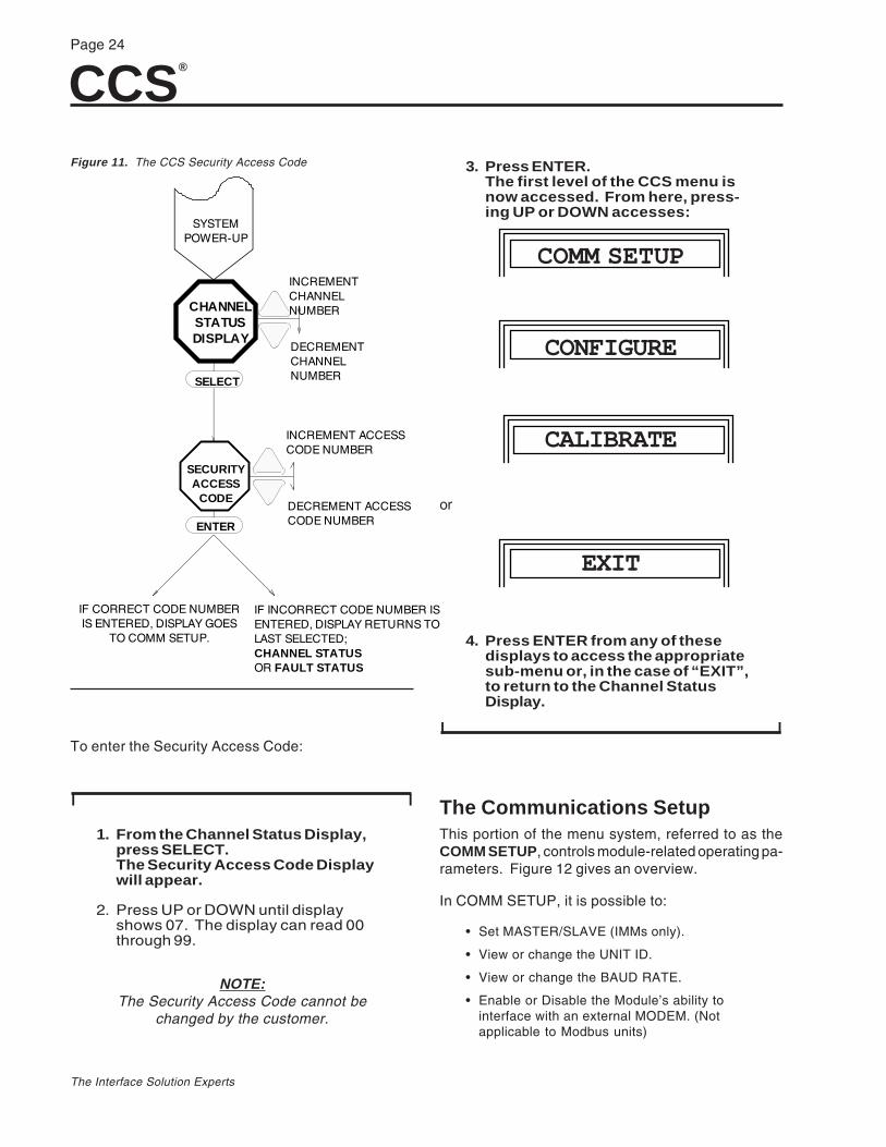
Figure 11 illustrates the procedure for bringing up andentering the Security Access Code.
CCS®
Page 24
The Interface Solution Experts
SECURITYACCESS
CODE
SYSTEMPOWER-UP
CHANNELSTATUSDISPLAY
IF INCORRECT CODE NUMBER IS ENTERED, DISPLAY RETURNS TO LAST SELECTED;CHANNEL STATUSOR FAULT STATUS
INCREMENT ACCESS CODE NUMBER
DECREMENT ACCESS CODE NUMBER
IF CORRECT CODE NUMBER IS ENTERED, DISPLAY GOES
TO COMM SETUP.
ENTER
SELECT
INCREMENT CHANNEL NUMBER
DECREMENT CHANNEL NUMBER
To enter the Security Access Code:
I I
1. From the Channel Status Display,press SELECT.The Security Access Code Displaywill appear.
2. Press UP or DOWN until displayshows 07. The display can read 00through 99.
NOTE:The Security Access Code cannot be
changed by the customer.
3. Press ENTER.The first level of the CCS menu isnow accessed. From here, press-ing UP or DOWN accesses:
COMM SETUP
CONFIGURE
CALIBRATE
or
EXIT
4. Press ENTER from any of thesedisplays to access the appropriatesub-menu or, in the case of “EXIT”,to return to the Channel StatusDisplay.
I I
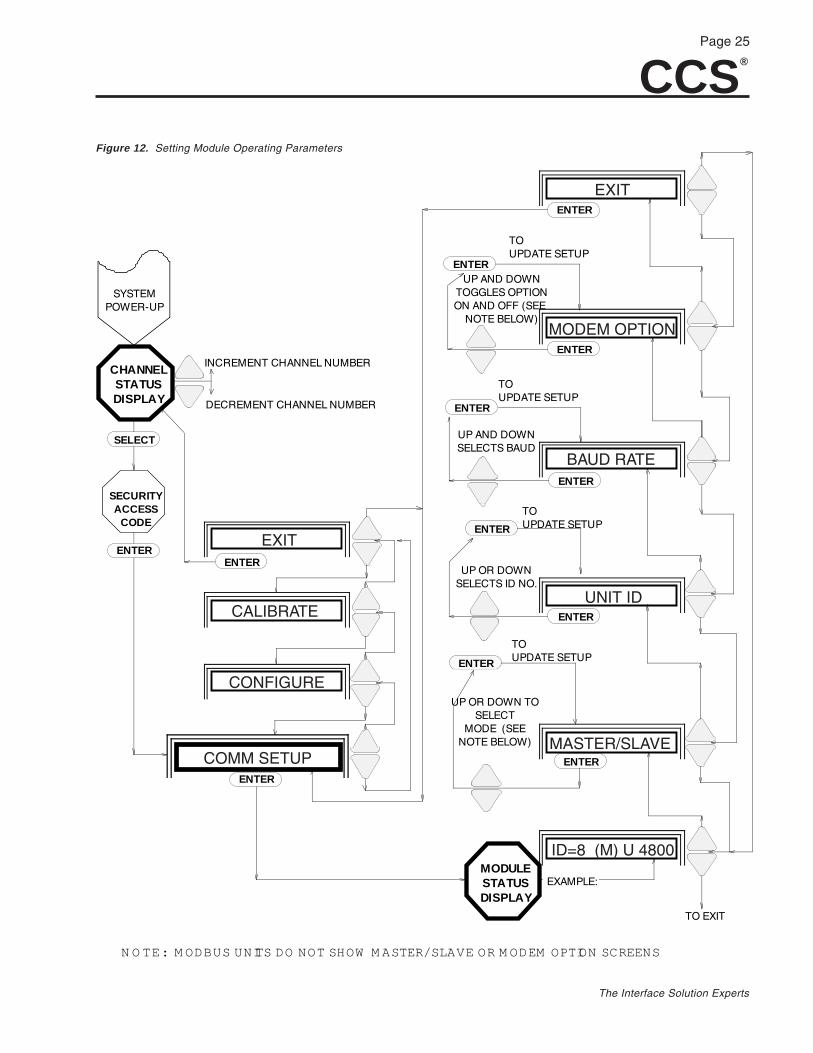
The Communications SetupThis portion of the menu system, referred to as theCOMM SETUP, controls module-related operating pa-rameters. Figure 12 gives an overview.
In COMM SETUP, it is possible to:
• Set MASTER/SLAVE (IMMs only).
• View or change the UNIT ID.
• View or change the BAUD RATE.
• Enable or Disable the Module’s ability tointerface with an external MODEM. (Notapplicable to Modbus units)
Figure 11. The CCS Security Access Code
CCS®
Page 25
The Interface Solution Experts
INCREMENT CHANNEL NUMBER
DECREMENT CHANNEL NUMBER
MODULESTATUSDISPLAY
SYSTEMPOWER-UP
CHANNELSTATUSDISPLAY
SECURITYACCESS
CODE
EXAMPLE:
TO EXIT
UP OR DOWN TO SELECT
MODE (SEE NOTE BELOW)
TOUPDATE SETUP
UP OR DOWN SELECTS ID NO.
TOUPDATE SETUP
UP AND DOWN SELECTS BAUD
TOUPDATE SETUP
UP AND DOWN TOGGLES OPTIONON AND OFF (SEE
NOTE BELOW)
TOUPDATE SETUP
ENTER
SELECT
ENTER
ENTER
ENTER
ENTER
ENTER
ENTER
ENTER
ENTER
ENTER
ENTER
ENTER
N O TE: M ODBUS UNITS DO NOT SHOW M ASTER/SLAVE OR M ODEM OPTION SCREENS
CALIBRATE
EXIT
CONFIGURE
COMM SETUP
ID=8 (M) U 4800
MASTER/SLAVE
UNIT ID
BAUD RATE
MODEM OPTION
EXIT
Figure 12. Setting Module Operating Parameters
CCS®
Page 26
The Interface Solution Experts
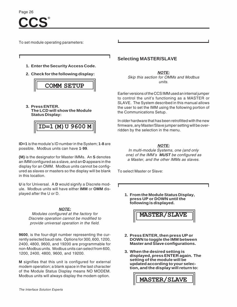
To set module operating parameters:
I I
1. Enter the Security Access Code.
2. Check for the following display:
COMM SETUP
3. Press ENTER.The LCD will show the ModuleStatus Display:
ID=1(M)U 9600 M
ID=1 is the module’s ID number in the System; 1-8 arepossible. Modbus units can have 1-99.
(M) is the designator for Master IMMs. An S denotesan IMM configured as a slave, and an O appears in thedisplay for an OMM. Modbus units cannot be config-ured as slaves or masters so the display will be blankin this location.
U is for Universal. A D would signify a Discrete mod-ule. Modbus units will have either IMM or OMM dis-played after the U or D.
NOTE:Modules configured at the factory for
Discrete operation cannot be modified toprovide universal operation in the field.
9600, is the four-digit number representing the cur-rently selected baud rate. Options for 300, 600, 1200,2400, 4800, 9600, and 19200 are programmable fornon-Modbus units. Modbus units can select from 600,1200, 2400, 4800, 9600, and 19200.
M signifies that this unit is configured for externalmodem operation; a blank space in the last characterof the Module Status Display means NO MODEM.Modbus units will always display the modem option.
I I
Selecting MASTER/SLAVE
NOTE:Skip this section for OMMs and Modbus
units.
Earlier versions of the CCS IMM used an internal jumperto control the unit’s functioning as a MASTER orSLAVE. The System described in this manual allowsthe user to set the IMM using the following portion ofthe Communications Setup.
In older hardware that has been retrofitted with the newfirmware, any Master/Slave jumper setting will be over-ridden by the selection in the menu.
NOTE:In multi-module Systems, one (and only
one) of the IMM’s MUST be configured asa Master, and the other IMMs as slaves.
To select Master or Slave:
I I
1. From the Module Status Display,press UP or DOWN until thefollowing is displayed.
MASTER/SLAVE
2. Press ENTER, then press UP orDOWN to toggle the IMM betweenMaster and Slave configurations.
3. When the desired setting isdisplayed, press ENTER again. Thesetting of the module will beupdated according to your selec-tion, and the display will return to:
MASTER/SLAVE
CCS®
Page 27
The Interface Solution Experts
4. Press UP or DOWN to access EXIT,or the next desired sub-menu, thenpress ENTER.
I I
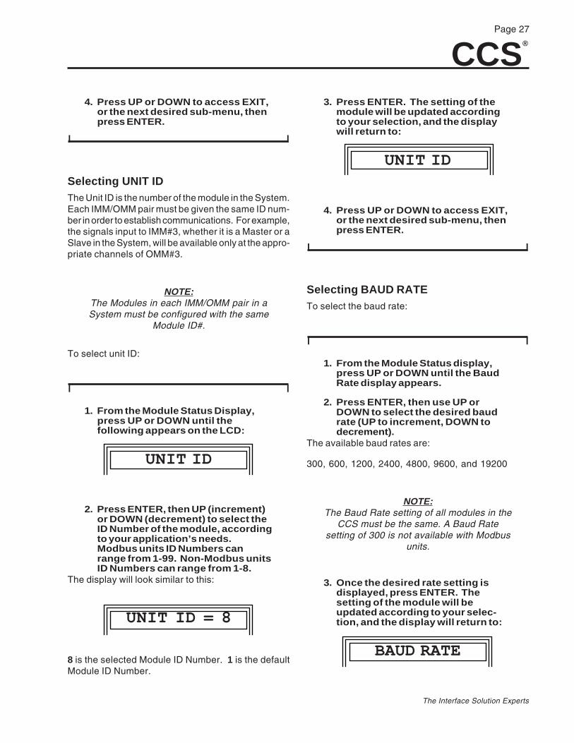
Selecting UNIT IDThe Unit ID is the number of the module in the System.Each IMM/OMM pair must be given the same ID num-ber in order to establish communications. For example,the signals input to IMM#3, whether it is a Master or aSlave in the System, will be available only at the appro-priate channels of OMM#3.
NOTE:The Modules in each IMM/OMM pair in aSystem must be configured with the same
Module ID#.
To select unit ID:
I I
1. From the Module Status Display,press UP or DOWN until thefollowing appears on the LCD:
UNIT ID
2. Press ENTER, then UP (increment)or DOWN (decrement) to select theID Number of the module, accordingto your application’s needs.Modbus units ID Numbers canrange from 1-99. Non-Modbus unitsID Numbers can range from 1-8.
The display will look similar to this:
UNIT ID = 8
8 is the selected Module ID Number. 1 is the defaultModule ID Number.
3. Press ENTER. The setting of themodule will be updated accordingto your selection, and the displaywill return to:
UNIT ID
4. Press UP or DOWN to access EXIT,or the next desired sub-menu, thenpress ENTER.
I I
Selecting BAUD RATETo select the baud rate:
I I
1. From the Module Status display,press UP or DOWN until the BaudRate display appears.
2. Press ENTER, then use UP orDOWN to select the desired baudrate (UP to increment, DOWN todecrement).
The available baud rates are:
300, 600, 1200, 2400, 4800, 9600, and 19200
NOTE:The Baud Rate setting of all modules in the
CCS must be the same. A Baud Ratesetting of 300 is not available with Modbus
units.
3. Once the desired rate setting isdisplayed, press ENTER. Thesetting of the module will beupdated according to your selec-tion, and the display will return to:
BAUD RATE
CCS®
Page 28
The Interface Solution Experts
4. Press UP or DOWN to EXIT, or thenext desired sub-menu, then pressENTER. The module will transmitand receive at that rate.
I I
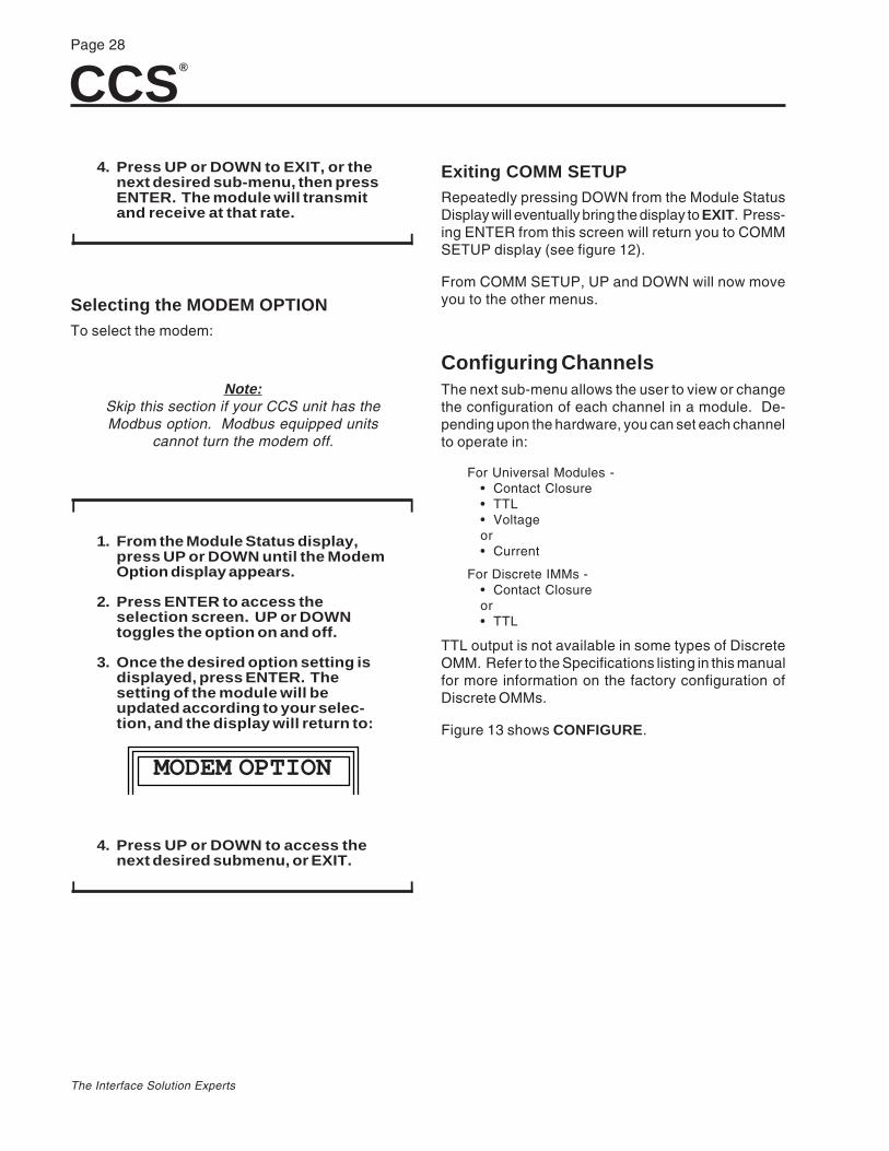
Selecting the MODEM OPTIONTo select the modem:
Note:Skip this section if your CCS unit has theModbus option. Modbus equipped units
cannot turn the modem off.
I I
1. From the Module Status display,press UP or DOWN until the ModemOption display appears.
2. Press ENTER to access theselection screen. UP or DOWNtoggles the option on and off.
3. Once the desired option setting isdisplayed, press ENTER. Thesetting of the module will beupdated according to your selec-tion, and the display will return to:
MODEM OPTION
4. Press UP or DOWN to access thenext desired submenu, or EXIT.
I I
Exiting COMM SETUPRepeatedly pressing DOWN from the Module StatusDisplay will eventually bring the display to EXIT. Press-ing ENTER from this screen will return you to COMMSETUP display (see figure 12).
From COMM SETUP, UP and DOWN will now moveyou to the other menus.
Configuring ChannelsThe next sub-menu allows the user to view or changethe configuration of each channel in a module. De-pending upon the hardware, you can set each channelto operate in:
For Universal Modules -• Contact Closure• TTL• Voltageor• Current
For Discrete IMMs -• Contact Closureor• TTL
TTL output is not available in some types of DiscreteOMM. Refer to the Specifications listing in this manualfor more information on the factory configuration ofDiscrete OMMs.
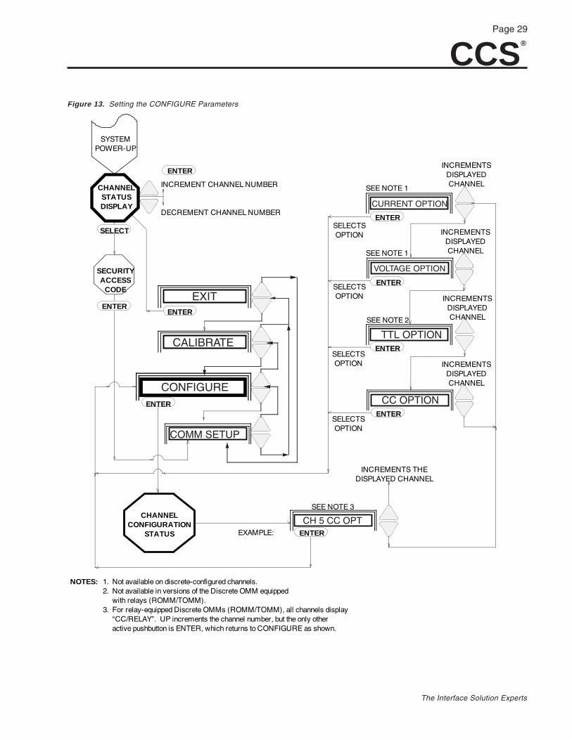
Figure 13 shows CONFIGURE.
CCS®
Page 29
The Interface Solution Experts
SYSTEMPOWER-UP
CHANNELSTATUSDISPLAY
SECURITYACCESS
CODE
CHANNELCONFIGURATION
STATUS EXAMPLE:
INCREMENTS THEDISPLAYED CHANNEL
INCREMENTSDISPLAYEDCHANNEL
INCREMENTSDISPLAYEDCHANNEL
INCREMENTSDISPLAYEDCHANNEL
INCREMENTSDISPLAYEDCHANNEL
SELECTSOPTION
SELECTSOPTION
SELECTSOPTION
SELECTSOPTION
SEE NOTE 1
SEE NOTE 1
SEE NOTE 2
ENTER
INCREMENT CHANNEL NUMBER
DECREMENT CHANNEL NUMBER
SELECT
ENTERENTER
ENTER
ENTER
1. Not available on discrete-configured channels. 2. Not available in versions of the Discrete OMM equipped with relays (ROMM/TOMM). 3. For relay-equipped Discrete OMMs (ROMM/TOMM), all channels display “CC/RELAY”. UP increments the channel number, but the only other active pushbutton is ENTER, which returns to CONFIGURE as shown.
NOTES:
ENTER
ENTER
ENTER
ENTER
SEE NOTE 3
EXIT
CALIBRATE
CONFIGURE
COMM SETUP
CC OPTION
TTL OPTION
VOLTAGE OPTION
CURRENT OPTION
CH 5 CC OPT
Figure 13. Setting the CONFIGURE Parameters
CCS®
Page 30
The Interface Solution Experts
To configure the channels:
I I
1. After power-up, input the SecurityAccess Code.
2. Press UP or DOWN until the LCDshows:
CONFIGURE
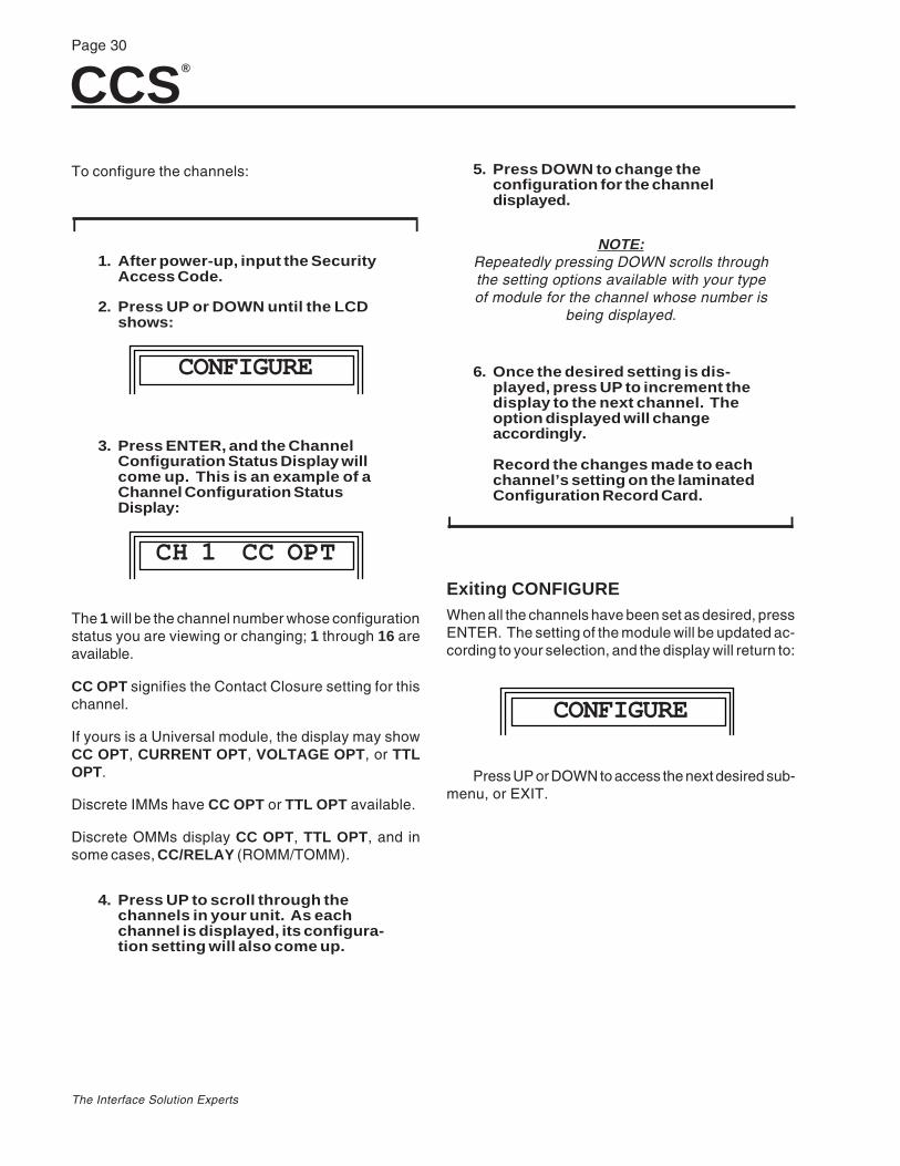
3. Press ENTER, and the ChannelConfiguration Status Display willcome up. This is an example of aChannel Configuration StatusDisplay:
CH 1 CC OPT
The 1 will be the channel number whose configurationstatus you are viewing or changing; 1 through 16 areavailable.
CC OPT signifies the Contact Closure setting for thischannel.
If yours is a Universal module, the display may showCC OPT, CURRENT OPT, VOLTAGE OPT , or TTLOPT.
Discrete IMMs have CC OPT or TTL OPT available.
Discrete OMMs display CC OPT, TTL OPT, and insome cases, CC/RELAY (ROMM/TOMM).
4. Press UP to scroll through thechannels in your unit. As eachchannel is displayed, its configura-tion setting will also come up.
5. Press DOWN to change theconfiguration for the channeldisplayed.
NOTE:Repeatedly pressing DOWN scrolls throughthe setting options available with your typeof module for the channel whose number is
being displayed.
6. Once the desired setting is dis-played, press UP to increment thedisplay to the next channel. Theoption displayed will changeaccordingly.
Record the changes made to eachchannel’s setting on the laminatedConfiguration Record Card.
I I
Exiting CONFIGUREWhen all the channels have been set as desired, pressENTER. The setting of the module will be updated ac-cording to your selection, and the display will return to:
CONFIGURE
Press UP or DOWN to access the next desired sub-menu, or EXIT.
CCS®
Page 31
The Interface Solution Experts
Converting OutputsIt is possible to convert the signals processed by themodules in your CCS. Current input can be presentedas voltage output, and vice-versa. It is suggested thatthe Module Configuration Record be used to note anyconverting.
Channel CalibrationThis sub-menu is the means by which the user setsthe zero and full scale values of analog channels (cur-rent and voltage), along with the default value of outputsignals in the OMM.
From CALIBRATE , the user can:
• Set default values or conditions that the outputchannels assume if the communication link islost.
• Set current or voltage to any desired valuewithin the range of the signal (refer to theSpecifications listing in this manual).
• Invert the outputs of discrete channels andunits.
Discrete IMMs, and the discrete-configured channelsof Universal IMMs have no options in the calibrate mode.They are input to the IMM as either high or low (for TTL),or opened or closed (for contact closure).
Discrete channels can be set for default conditions inthe OMM, but the channels are either on or off.
In the IMM, if a channel which has been configured forTTL or contact closure signals is selected for calibra-tion, the display will read:
NO OPTION
NOTES:Use the setup described in the Bench
Check of this manual when executing theInput/Output Calibration procedures.
The last changes made in the calibrationmode are retained in memory whenever
power is removed from the modules.
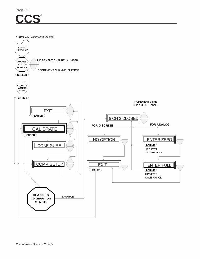
Figure 14 illustrates the CALIBRATE procedures forIMMs.
CCS®
Page 32
The Interface Solution Experts
EXIT
SYSTEMPOWER-UP
CHANNELSTATUSDISPLAY
SECURITYACCESS
CODE
CHANNELSCALIBRATION
STATUS
EXAMPLE:
INCREMENTS THEDISPLAYED CHANNEL
FOR DISCRETE FOR ANALOG
UPDATESCALIBRATION
UPDATESCALIBRATION
ENTER
SELECT
INCREMENT CHANNEL NUMBER
DECREMENT CHANNEL NUMBER
ENTER
ENTER
ENTER ENTER
ENTER
CALIBRATE
CONFIGURE
COMM SETUP
5 CH 2 CLOSED
NO OPTION
EXIT
ENTER ZERO
ENTER FULL
Figure 14. Calibrating the IMM
CCS®
Page 33
The Interface Solution Experts
Calibrating Analog IMM ChannelsTo calibrate Analog IMM Channels:
I I
1. To calibrate current or voltage inputchannels on Universal IMMs, enterthe security sequence and incre-ment the main menu to CALIBRATE.Press ENTER. The menu will bringup the Channel Calibration StatusDisplay. For example:
1 CH 1 65.4%
On your unit, the 1 represents the module ID number(1 through 8 or 01 through 99 for MODBUS units); CH1 is the channel number (1 through 16); and 65.4%represents the input signal as a percent of span (dis-crete channels display HIGH, LOW, OPEN orCLOSED).
2. Press UP to scroll through chan-nels.
3. To view the calibration options forthe displayed channel, pressDOWN. The display should show:
ENTER ZERO
If it shows:
NO OPTION
then this channel has been configured for discreteoperation.
a. To access the display for otherchannels, return to the ChannelCalibration Status Display. PressDOWN (to EXIT), then DOWN again,then go to Step 2 of this procedure.
4. Set the analog input signal to zeropercent of span. Press ENTER.
The zero value is based on the inputvalue present at the terminals whenENTER is pressed. The displayreturns to the Channel CalibrationStatus Display. It will show, forexample:
1 CH 1 00.0%
5. From the Channel Calibration Status Display, pressDOWN twice; the display will show:
ENTER FULL
6. Set the analog input signal to thefull scale value, and press ENTER.
The full scale value is based on theinput value present at the terminalswhen ENTER is pressed. Thedisplay will return to the ChannelCalibration Status Display.
7. To calibrate another analogchannel, press UP until the desiredchannel is displayed and repeatsteps 3 - 6.
NOTE:The Full Scale value should always be
higher than the Zero value.
I I
Calibrating Universal OMM ChannelsFigure 15 shows the procedure to calibrate universalOMM channels. To calibrate current or voltage outputchannels, enter the Security Access Code and pressDOWN until the CALIBRATE display appears, thenpress ENTER. The menu will bring up the ChannelCalibration Status Display.
To calibrate universal OMM channels:
CCS®
Page 34
The Interface Solution Experts
SYSTEMPOWER-UP
CHANNELSTATUSDISPLAY
SECURITYACCESS
CODE
CHANNELSCALIBRATION
STATUS
EXAMPLE:
ENTER
INCREMENTS THEDISPLAYED CHANNEL
UPDATESCALIBRATION
UPDATESCALIBRATION
UPDATESCALIBRATION
ENABLESFEATURE
FOR DISCRETE FOR ANALOG
INCREMENTSZERO
DECREMENTS
ZERO
INCREMENTSFULL SCALE
DECREMENTSFULL SCALE
UPDATESCALIBRATION
UPDATESCALIBRATION
INCREMENTSDEFAULT OUTPUT
UPDATESCALIBRATION
DECREMENTSDEFAULT OUTPUT
(SEE NOTE 1)
(SEE NOTE 1)
(SEE NOTE 1)
(SEE NOTE 1)
(SEE NOTE 1)
(SEE NOTE 1)
(SEE NOTE 2)
(SEE NOTE 3)
ENTER
SELECT
INCREMENT CHANNEL NUMBER
DECREMENT CHANNEL NUMBER
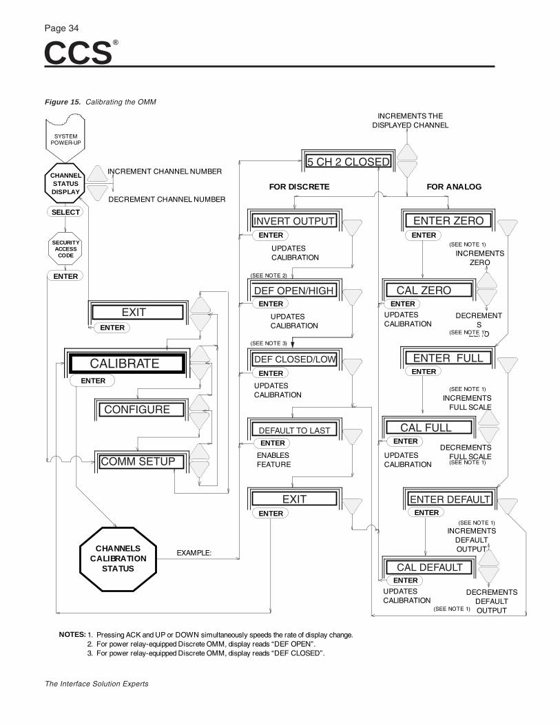
1. Pressing ACK and UP or DOWN simultaneously speeds the rate of display change. 2. For power relay-equipped Discrete OMM, display reads “DEF OPEN”. 3. For power relay-equipped Discrete OMM, display reads “DEF CLOSED”.
NOTES:
ENTER
ENTER
ENTER
ENTER
ENTER
ENTER ENTER
ENTER
ENTER
ENTER
ENTER
ENTER
EXIT
CALIBRATE
CONFIGURE
COMM SETUP
5 CH 2 CLOSED
INVERT OUTPUT
EXIT
DEF OPEN/HIGH
DEF CLOSED/LOW
DEFAULT TO LAST
ENTER ZERO
CAL ZERO
ENTER FULL
CAL FULL
ENTER DEFAULT
CAL DEFAULT
Figure 15. Calibrating the OMM
CCS®
Page 35
The Interface Solution Experts
I I
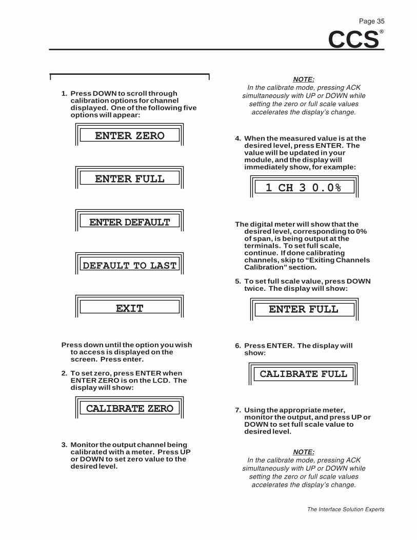
1. Press DOWN to scroll throughcalibration options for channeldisplayed. One of the following fiveoptions will appear:
ENTER ZERO
ENTER FULL
ENTER DEFAULT
DEFAULT TO LAST
EXIT
Press down until the option you wishto access is displayed on thescreen. Press enter.
2. To set zero, press ENTER whenENTER ZERO is on the LCD. Thedisplay will show:
CALIBRATE ZERO
3. Monitor the output channel beingcalibrated with a meter. Press UPor DOWN to set zero value to thedesired level.
NOTE:In the calibrate mode, pressing ACK
simultaneously with UP or DOWN whilesetting the zero or full scale valuesaccelerates the display’s change.
4. When the measured value is at thedesired level, press ENTER. Thevalue will be updated in yourmodule, and the display willimmediately show, for example:
1 CH 3 0.0%
The digital meter will show that thedesired level, corresponding to 0%of span, is being output at theterminals. To set full scale,continue. If done calibratingchannels, skip to “Exiting ChannelsCalibration” section.
5. To set full scale value, press DOWNtwice. The display will show:
ENTER FULL
6. Press ENTER. The display willshow:
CALIBRATE FULL
7. Using the appropriate meter,monitor the output, and press UP orDOWN to set full scale value todesired level.
NOTE:In the calibrate mode, pressing ACK
simultaneously with UP or DOWN whilesetting the zero or full scale valuesaccelerates the display’s change.

CCS®
Page 36
The Interface Solution Experts
8. When the measured value is at thedesired level, press ENTER. Thevalue will be updated in yourmodule, and the display willimmediately show 100% of inputspan. For example:
1 CH 3 100%
9. To calibrate another analogchannel, press UP until the desiredchannel is displayed. Repeat steps2 through 8.
I I
Setting Default ValuesWith the desired analog channel displayed on theChannel Calibration Status, press DOWN until the dis-play shows:
ENTER DEFAULT
To calibrate default values:
I I
1. Press ENTER. The display shows:
CALIBRATE DEF
2. Monitor output channel with theappropriate meter, and press UP orDOWN to set the full scale value todesired level.
NOTE:In the calibrate mode, pressing ACK
simultaneously with UP or DOWN whilesetting the zero or full scale valuesaccelerates the display’s change.
3. Press ENTER when the correctvalue is displayed.Menu will display, for example:
1 CH 3 50. 0%
4. To set the default value of anotheranalog channel, press UP untildesired channel is displayed, thenrepeat steps 1 through 4.
I I
Enabling Default to LastWith this feature, the module uses the signal levelpresent at time of communication fault as the defaultuntil communications are restored. This is useful formaintaining a “status quo” until the link problem canbe fixed.
I I
1. Press UP until the desired analogchannel is displayed.
2. Press DOWN until the displayshows:
DEFAULT TO LAST
3. Press ENTER. The Menu will returnto the Channel Calibration StatusDisplay.
I I
Whenever a link failure occurs, the levels at all chan-nels with the Default to Last parameter “enabled” willbe maintained until the communications link is restored.
Until communications are restored, the display and theoutput will consist of this last value, and include a D toindicate the level being maintained is the default. Forexample:
CCS®
Page 37
The Interface Solution Experts
1 CH 3 25.0% D
The FAULT LED on the front panel will also flash. Re-fer to the Troubleshooting Section of this manual forinstructions on clearing alarms.
Upon re-establishment of the link, the System will re-turn to normal operating conditions as determined bythe configuration parameters set prior to the link fail-ure.
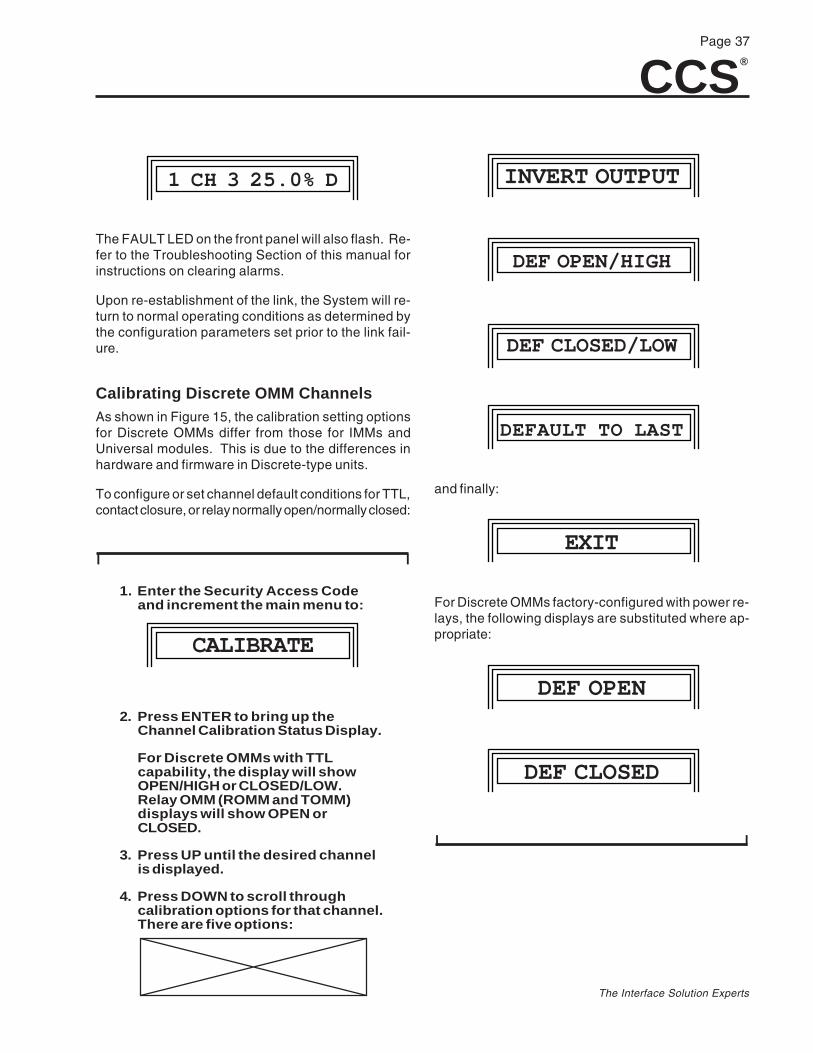
Calibrating Discrete OMM ChannelsAs shown in Figure 15, the calibration setting optionsfor Discrete OMMs differ from those for IMMs andUniversal modules. This is due to the differences inhardware and firmware in Discrete-type units.
To configure or set channel default conditions for TTL,contact closure, or relay normally open/normally closed:
I I
1. Enter the Security Access Codeand increment the main menu to:
CALIBRATE
2. Press ENTER to bring up theChannel Calibration Status Display.
For Discrete OMMs with TTLcapability, the display will showOPEN/HIGH or CLOSED/LOW.Relay OMM (ROMM and TOMM)displays will show OPEN orCLOSED.
3. Press UP until the desired channelis displayed.
4. Press DOWN to scroll throughcalibration options for that channel.There are five options:
INVERT OUTPUT
DEF OPEN/HIGH
DEF CLOSED/LOW
DEFAULT TO LAST
and finally:
EXIT
For Discrete OMMs factory-configured with power re-lays, the following displays are substituted where ap-propriate:
DEF OPEN
DEF CLOSED
I I
CCS®
Page 38
The Interface Solution Experts
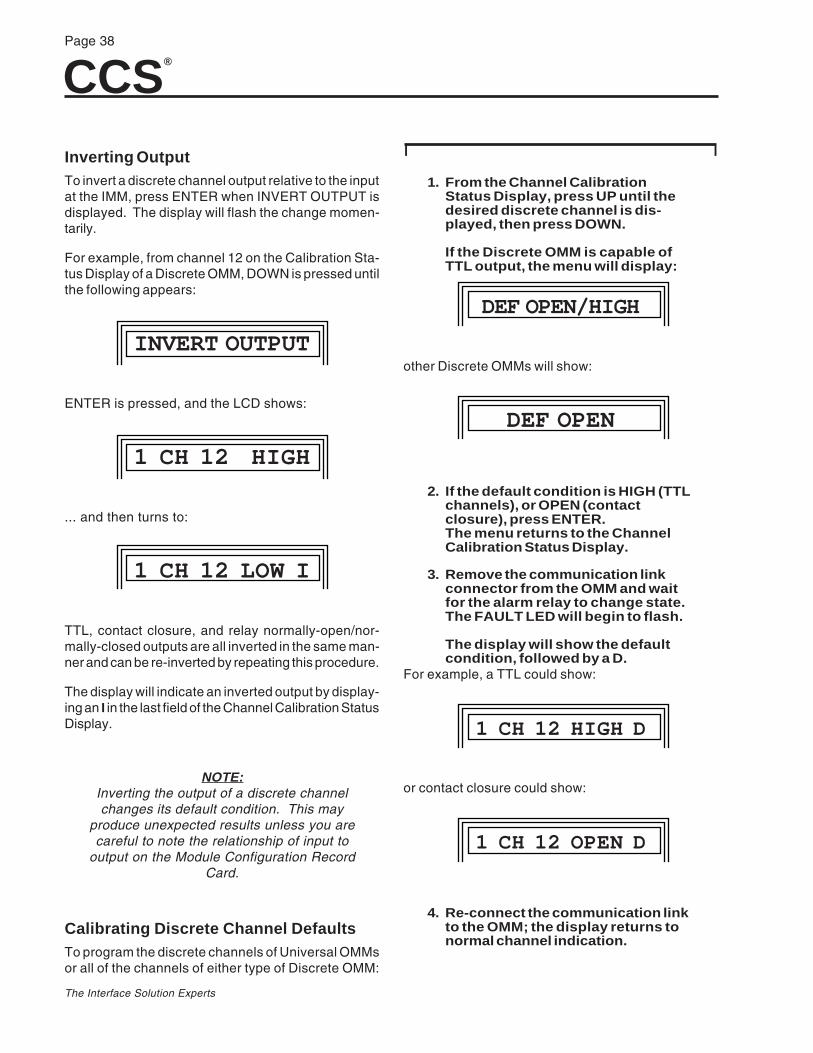
Inverting OutputTo invert a discrete channel output relative to the inputat the IMM, press ENTER when INVERT OUTPUT isdisplayed. The display will flash the change momen-tarily.
For example, from channel 12 on the Calibration Sta-tus Display of a Discrete OMM, DOWN is pressed untilthe following appears:
INVERT OUTPUT
ENTER is pressed, and the LCD shows:
1 CH 12 HIGH
... and then turns to:
1 CH 12 LOW I
TTL, contact closure, and relay normally-open/nor-mally-closed outputs are all inverted in the same man-ner and can be re-inverted by repeating this procedure.
The display will indicate an inverted output by display-ing an I in the last field of the Channel Calibration StatusDisplay.
NOTE:Inverting the output of a discrete channelchanges its default condition. This may
produce unexpected results unless you arecareful to note the relationship of input to
output on the Module Configuration RecordCard.
Calibrating Discrete Channel DefaultsTo program the discrete channels of Universal OMMsor all of the channels of either type of Discrete OMM:
I I
1. From the Channel CalibrationStatus Display, press UP until thedesired discrete channel is dis-played, then press DOWN.
If the Discrete OMM is capable ofTTL output, the menu will display:
DEF OPEN/HIGH
other Discrete OMMs will show:
DEF OPEN
2. If the default condition is HIGH (TTLchannels), or OPEN (contactclosure), press ENTER.The menu returns to the ChannelCalibration Status Display.
3. Remove the communication linkconnector from the OMM and waitfor the alarm relay to change state.The FAULT LED will begin to flash.
The display will show the defaultcondition, followed by a D.
For example, a TTL could show:
1 CH 12 HIGH D
or contact closure could show:
1 CH 12 OPEN D
4. Re-connect the communication linkto the OMM; the display returns tonormal channel indication.
CCS®
Page 39
The Interface Solution Experts
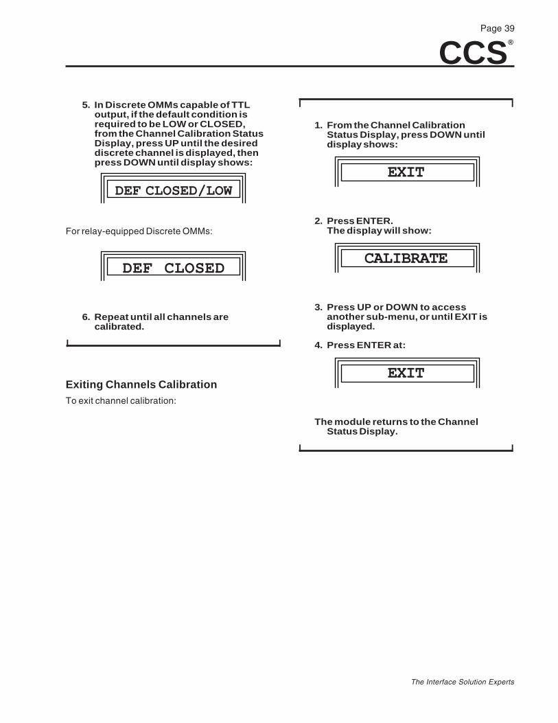
5. In Discrete OMMs capable of TTLoutput, if the default condition isrequired to be LOW or CLOSED,from the Channel Calibration StatusDisplay, press UP until the desireddiscrete channel is displayed, thenpress DOWN until display shows:
DEF CLOSED/LOW
For relay-equipped Discrete OMMs:
DEF CLOSED
6. Repeat until all channels arecalibrated.
I I
Exiting Channels CalibrationTo exit channel calibration:
I I
1. From the Channel CalibrationStatus Display, press DOWN untildisplay shows:
EXIT
2. Press ENTER.The display will show:
CALIBRATE
3. Press UP or DOWN to accessanother sub-menu, or until EXIT isdisplayed.
4. Press ENTER at:
EXIT
The module returns to the ChannelStatus Display.
I I
CCS®
Page 40
The Interface Solution Experts
1 2 3 24 VDCA B S A B S LINK
XMT RCV FAULT
ACK
222.25 mm(8.75 in)
91.45 mm(3.60 in)
116.85 mm(4.60 in)
91.45 mm(3.60 in)
127 mm(5.00 in)
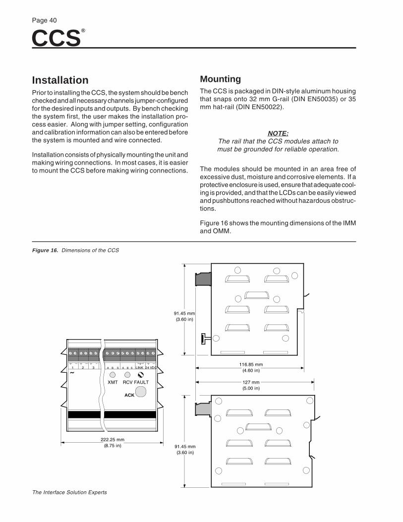
InstallationPrior to installing the CCS, the system should be benchchecked and all necessary channels jumper-configuredfor the desired inputs and outputs. By bench checkingthe system first, the user makes the installation pro-cess easier. Along with jumper setting, configurationand calibration information can also be entered beforethe system is mounted and wire connected.
Installation consists of physically mounting the unit andmaking wiring connections. In most cases, it is easierto mount the CCS before making wiring connections.
MountingThe CCS is packaged in DIN-style aluminum housingthat snaps onto 32 mm G-rail (DIN EN50035) or 35mm hat-rail (DIN EN50022).
NOTE:The rail that the CCS modules attach tomust be grounded for reliable operation.
The modules should be mounted in an area free ofexcessive dust, moisture and corrosive elements. If aprotective enclosure is used, ensure that adequate cool-ing is provided, and that the LCDs can be easily viewedand pushbuttons reached without hazardous obstruc-tions.
Figure 16 shows the mounting dimensions of the IMMand OMM.
Figure 16. Dimensions of the CCS
CCS®
Page 41
The Interface Solution Experts
Wiring ConnectionsAll wiring connections are made with removable termi-nal plugs that are “shaped” to prevent insertion in thewrong orientation. The terminal plugs accept wire sizes14 to 30 AWG. A shielded, twisted pair of 24 AWGcopper wires is recommended for the communicationlink.
All terminal plugs can be easily removed and reinserted.Power should be removed from a module before con-necting or disconnecting any terminal plugs.
CAUTION:Ensure that only input or output signals are
connected to input/output channels. DONOT connect DC power to channel
terminals; damage will result.
Each CCS set has two LINK terminals. Either LINKterminal can be used to make a single communicationlink. Each link uses a three-terminal plug, and in eachmodule, each link is electrically identical; pin A is wiredto pin A, B is wired to B, and S to S.
To link an IMM to an OMM, a shielded, twisted-wirepair is required and would be connected to terminalsA and B with the shield connected to the S terminal ateither or both modules. In a multi-IMM connectionscenario, or “daisy chain”, both terminals are used.
The fault contact terminal has a single two-connectorterminal plug for connection to external alarm circuits.Power is supplied to each module via a single two-connector terminal plug.
If the application uses a dc power source, connect thepositive (+) power connection to the “+” CCS moduleterminal and the negative (–) power connection to the“–” CCS module terminal.
Refer to the Ordering Information Table for specifica-tions.
Figure 17 shows a typical hookup diagram for an IMM.Figure 18 illustrates a typical hookup diagram for anOMM. Figure 19 shows a typical hookup diagram forIMMs and OMMs with Modbus.
Input and output devices will vary from those shown inthese figures.
Figures 20 through 31 illustrate hookups for systemsthat use various types of field devices.
These are provided for instructional purposes only.Your field devices and the method of connection maydiffer.

CCS®
Page 42
The Interface Solution Experts
+ –
1
+ –
24VDC
+ –
16 LINK LINKA B S A B S
117VAC (TYPICAL)
IPT–
+
A B S
POWERSUPPLY–
+
TO REMOTE DEVICE3–15 psig
SUPPLY20psi
ALARM
FAULTCONTACT
FROM IMMCOMM LINKSEE NOTES
NOTES: 1. Either comm link may be used.2. For the comm link, a twisted-wire pair must be used (minimum).
If a shielded twisted-wire pair is used, connect the shieldto the "S" terminal at either or both modules.
+ –
1
+ –
24VDC
+ –
16 LINK LINKA B S A B S
COMM LINK(TO OMM)
117VAC(TYPICAL)
RBX+
A B S
POWERSUPPLY
+
POWERSUPPLY +
117VAC
RTD
ALARM
SEENOTE 1
FAULTCONTACT
NOTES: 1. Either comm link may be used.2. For the comm link, a twisted-wire pair must be used (minimum).
If a shielded twisted-wire pair is used, connect the shieldto the "S" terminal at either or both modules.
Figure 17. Connecting the IMM
Figure 18. Connecting the OMM

CCS®
Page 43
The Interface Solution Experts
INTERNAL CIRCUITRY
4-20mA
FIELD WIRING
+ IN
– IN
IMM ANALOGCURRENT
INPUTFIELD TRANSMITTING
DEVICE
LOOPPOWERED
TRANSMITTER
250½
RBX– OUT
+ OUT
A
B
RTD
DPS– +
AC ACC
ANALOG MUXCHIP
CONVERTER(IF NEEDED)
UP TO 32 UNITS
RS232 RS485
CONNECT A TO +DATACONNECT B TO –DATA
+ DATA–DATA
24VDCPOWERSUPPLY
24VDCPOWERSUPPLY
+– +–
+–24VDC
POWERSUPPLY
+–24 VDCPOWERSUPPLY
FIELD DEVICES FIELD DEVICES
FIELD DEVICESFIELD DEVICES
X M T R C V F A U L T
ENTERSELECT
I NPUTM O DULE
ACK
P A T E N T P E N D IN G
C A B L E C O N C E N T R A T O R S Y S T E M
A B S A B S + –
X M T R C V F A U L T
ENTERSELECT
O UTPUTM O DULE
ACK
P A T E N T P E N D IN G
C A B L E C O N C E N T R A T O R S Y S T E M
A B S A B S
X M T R C V F A U L T
ENTERSELECT
I NPUTM O DULE
ACK
P A T E N T P E N D IN G
C A B L E C O N C E N T R A T O R S Y S T E M
A B S A B S
X M T R C V F A U L T
ENTERSELECT
O UTPUTM O DULE
ACK
P A T E N T P E N D IN G
C A B L E C O N C E N T R A T O R S Y S T E M
A B S A B S
IMM OMM
IMMIMM
Figure 19. Connecting Multiple IMM and OMM Modules with Modbus
Figure 20. Connecting IMM Analog Current Input (Loop Powered Field Device)
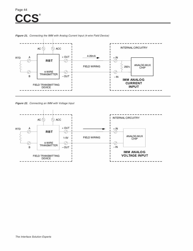
CCS®
Page 44
The Interface Solution Experts
FIELD WIRING
+ IN
– IN
IMM ANALOGVOLTAGE INPUTFIELD TRANSMITTING
DEVICE
4-WIRETRANSMITTER
RBT+ OUT
– OUT
A
B
RTD
ANALOG MUXCHIP
AC ACC
1-5V
INTERNAL CIRCUITRY
4-20mA
FIELD WIRING
+ IN
– INIMM ANALOG
CURRENT INPUT
FIELD TRANSMITTINGDEVICE
4-WIRETRANSMITTER
RBT+ OUT
– OUT
A
B
RTD
ANALOG MUXCHIP
AC ACC INTERNAL CIRCUITRY
250½
Figure 21. Connecting the IMM with Analog Current Input (4-wire Field Device)
Figure 22. Connecting an IMM with Voltage Input
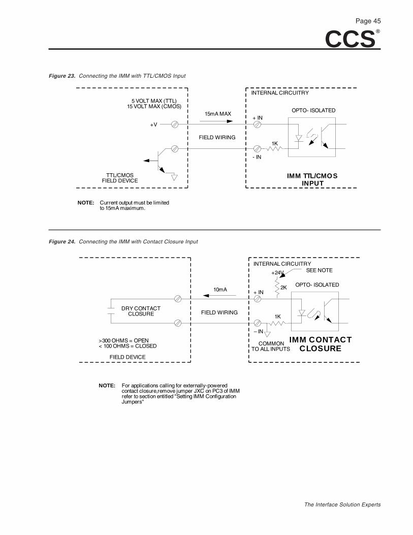
CCS®
Page 45
The Interface Solution Experts
INTERNAL CIRCUITRY
10mA
FIELD WIRING
+ IN
– IN
IMM CONTACT CLOSURE
OPTO- ISOLATED
FIELD DEVICE
DRY CONTACTCLOSURE
+24V
2K
1K
COMMONTO ALL INPUTS
>300 OHMS = OPEN< 100 OHMS = CLOSED
SEE NOTE
NOTE: For applications calling for externally-poweredcontact closure,remove jumper JXC on PC3 of IMMrefer to section entitled "Setting IMM ConfigurationJumpers"
INTERNAL CIRCUITRY
15mA MAX
FIELD WIRING
+ IN
- IN
IMM TTL/CMOSINPUT
OPTO- ISOLATED
TTL/CMOSFIELD DEVICE
5 VOLT MAX (TTL)15 VOLT MAX (CMOS)
+V
1K
NOTE: Current output must be limitedto 15mA maximum.
Figure 23. Connecting the IMM with TTL/CMOS Input
Figure 24. Connecting the IMM with Contact Closure Input
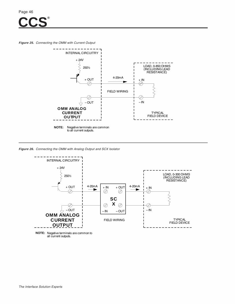
CCS®
Page 46
The Interface Solution Experts
INTERNAL CIRCUITRY
4-20mA
FIELD WIRING
+ IN
– IN
TYPICALFIELD DEVICE
OMM ANALOGCURRENT OUTPUT
– OUT
+ OUT
+ 24V
LOAD, 0-300 OHMS(INCLUDING LEAD
RESISTANCE)
4-20mA + IN
– IN
+ OUT
– OUT
SCX
250½
NOTE: Negative terminals are common toall current outputs.
4-20mA
FIELD WIRING
+ IN
– IN
LOAD, 0-850 OHMS(INCLUDING LEAD
RESISTANCE)
TYPICALFIELD DEVICE
INTERNAL CIRCUITRY
OMM ANALOGCURRENT OUTPUT
– OUT
+ OUT
+ 24V
250½
NOTE: Negative terminals are commonto all current outputs.
Figure 25. Connecting the OMM with Current Output
Figure 26. Connecting the OMM with Analog Output and SCX Isolator
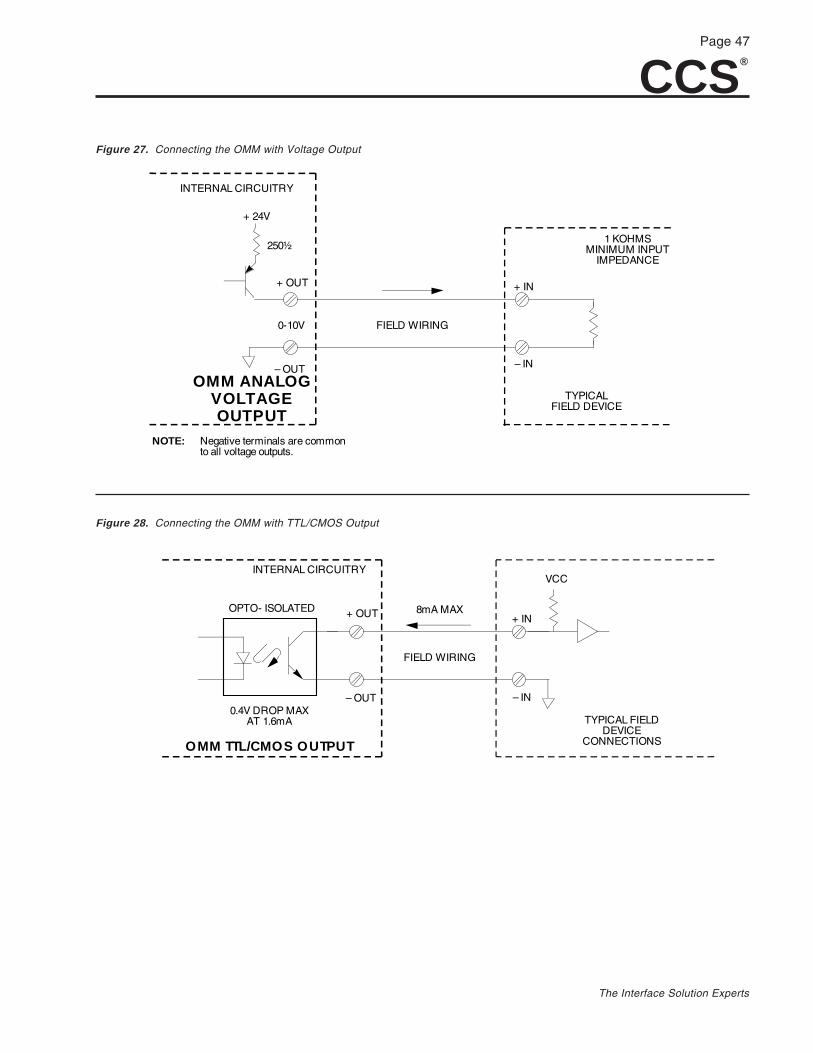
CCS®
Page 47
The Interface Solution Experts
8mA MAX
FIELD WIRING
+ IN
TYPICAL FIELDDEVICE
CONNECTIONS
OPTO- ISOLATED
0.4V DROP MAXAT 1.6mA
INTERNAL CIRCUITRYVCC
+ OUT
OMM TTL/CMOS OUTPUT
– IN– OUT
INTERNAL CIRCUITRY
FIELD WIRING
+ IN
– IN
TYPICALFIELD DEVICE
OMM ANALOGVOLTAGE OUTPUT
– OUT
+ OUT
0-10V
+ 24V
250½
NOTE: Negative terminals are commonto all voltage outputs.
1 KOHMSMINIMUM INPUT
IMPEDANCE
Figure 27. Connecting the OMM with Voltage Output
Figure 28. Connecting the OMM with TTL/CMOS Output
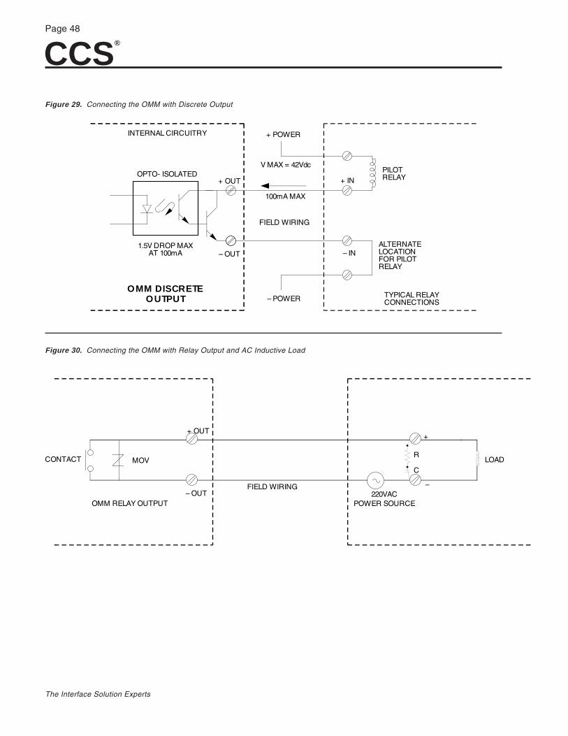
CCS®
Page 48
The Interface Solution Experts
PILOTRELAY
100mA MAX
FIELD WIRING
+ IN
– IN
TYPICAL RELAYCONNECTIONS
OPTO- ISOLATED
1.5V DROP MAXAT 100mA
INTERNAL CIRCUITRY
+ OUT
– OUT
OMM DISCRETE OUTPUT
+ POWER
V MAX = 42Vdc
– POWER
ALTERNATELOCATIONFOR PILOTRELAY
Figure 29. Connecting the OMM with Discrete Output
Figure 30. Connecting the OMM with Relay Output and AC Inductive Load
+
– – OUT
+ OUT
CONTACT
OMM RELAY OUTPUT
FIELD WIRING220VAC
POWER SOURCE
MOVC
RLOAD
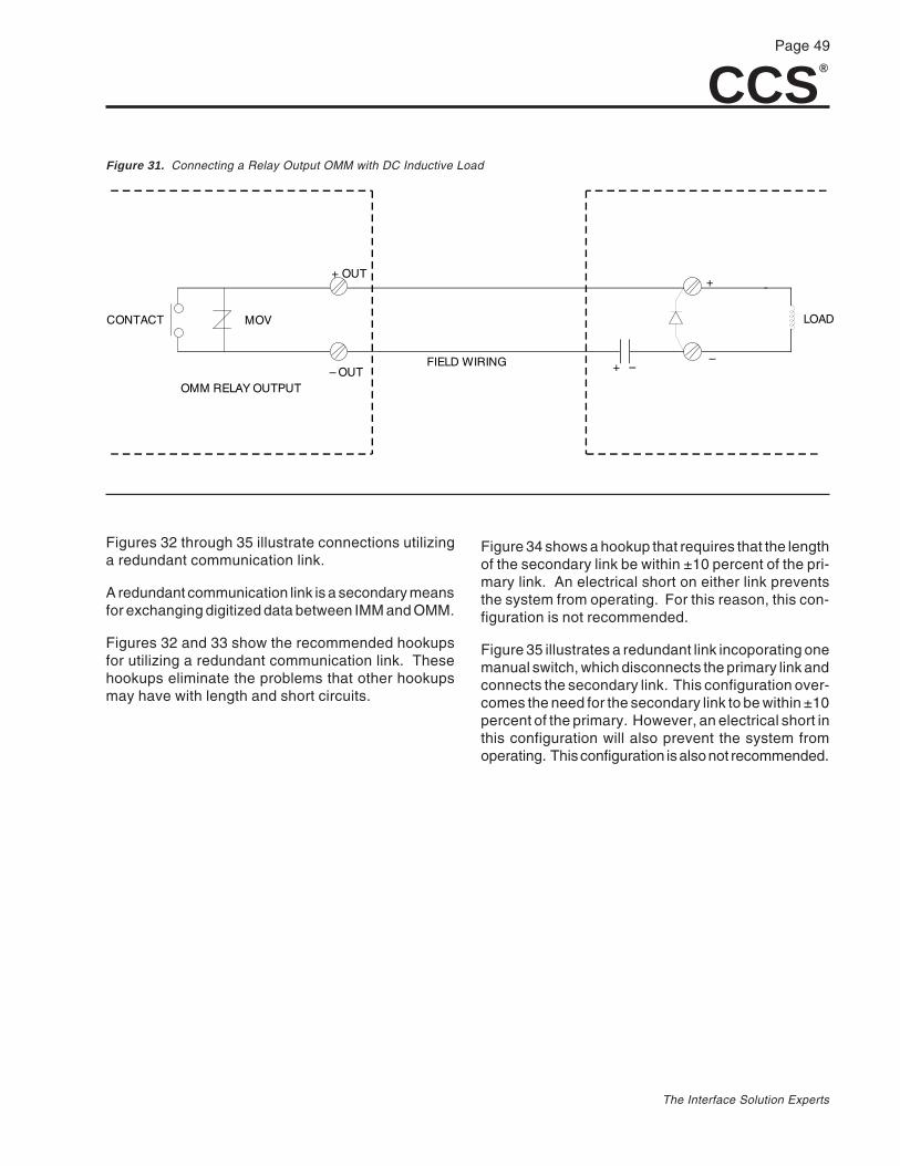
CCS®
Page 49
The Interface Solution Experts
+
– – OUT
+ OUT
CONTACT
OMM RELAY OUTPUT
FIELD WIRING
MOV LOAD
+ –
Figures 32 through 35 illustrate connections utilizinga redundant communication link.
A redundant communication link is a secondary meansfor exchanging digitized data between IMM and OMM.
Figures 32 and 33 show the recommended hookupsfor utilizing a redundant communication link. Thesehookups eliminate the problems that other hookupsmay have with length and short circuits.
Figure 31. Connecting a Relay Output OMM with DC Inductive Load
Figure 34 shows a hookup that requires that the lengthof the secondary link be within ±10 percent of the pri-mary link. An electrical short on either link preventsthe system from operating. For this reason, this con-figuration is not recommended.
Figure 35 illustrates a redundant link incoporating onemanual switch, which disconnects the primary link andconnects the secondary link. This configuration over-comes the need for the secondary link to be within ±10percent of the primary. However, an electrical short inthis configuration will also prevent the system fromoperating. This configuration is also not recommended.

CCS®
Page 50
The Interface Solution Experts
A B S
REDUNDANT LINK
IMM
OMMA B S
MAIN LINK
R
L
M
R
L
M
24VDC
24VDC
A B S A B S
MAIN LINK
REDUNDANT LINK
IMM OMM
Figure 32. Connecting Dual Manual Switches in a Redundant Communication Link
Figure 33. Connecting an Automatically Switched Redundant Communications Link
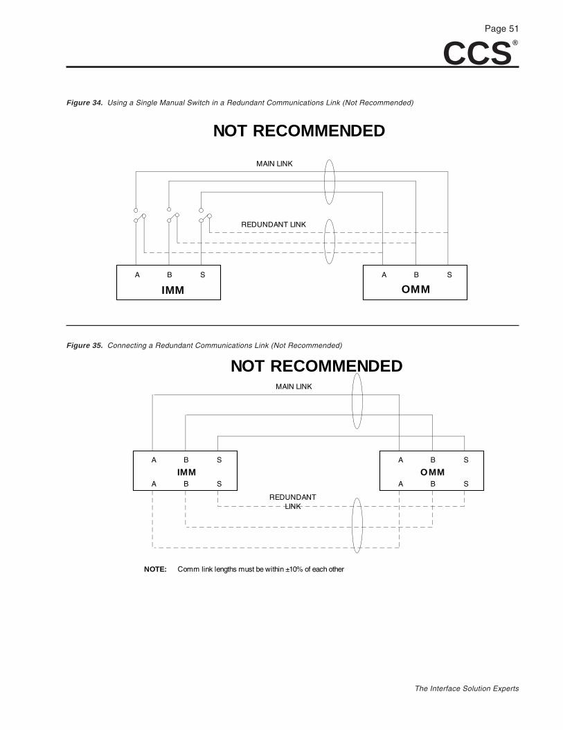
CCS®
Page 51
The Interface Solution Experts
MAIN LINK
REDUNDANT LINK
A B S A B S
A B S A B S
OMMIMM
NOT RECOMMENDED
NOTE: Comm link lengths must be within ±10% of each other
A B S A B S
MAIN LINK
REDUNDANT LINK
IMM OMM
NOT RECOMMENDED
Figure 34. Using a Single Manual Switch in a Redundant Communications Link (Not Recommended)
Figure 35. Connecting a Redundant Communications Link (Not Recommended)

CCS®
Page 52
The Interface Solution Experts
OperationOnce installed, the CCS operates unattended. TheSystem Menu displays on the IMM and OMM providesignal value/condition information for each channelused.
On power-up, all OMM outputs are initialized to zero oropen, according to the hardware being used. The OMMthen maintains zero or open until the first data mes-sage is received from its paired IMM. If a communica-tion failure timeout occurs, the outputs are set to defaultvalues.
Range Limits. The range of default values that can bedisplayed for analog-configured channels is from -5%to 105%. When actual values from the application ex-ceed this range, the LCD will begin to flash the mini-mum (-5%) or maximum (105%), indicating under orover range, respectively.
Data Format for Modbus UnitsIMMs and OMMs equipped with Modbus use a differ-ent data format. They use the 16-bit, signed, two’scomplement format with a data range of –32768 to+32767. When queried, a register will produce a two’scomplement number. Using a calculator, you canconvert the two’s complement to hex and then to deci-mal to obtain the value of the reading, representingpercent of scale multiplied by 100.
The CCS data string follows this format:
s ddd dddd dddd dddd
s = Sign bit: 0 = positive; 1 = negatived = data. The data is the binary equivalent in two’scomplement format of percent times 100 (% x 100).Data is clamped between: –5.00%(FE0CH) and+105.00%(2904H).
For example:
–1% = –(1x100) = –(100) = –(64H) = FF9CH
or
75.00% = 75x100 = 7500 = 1D4CH
For reference, the following is the data representationof the 16-bit, signed, two’s complement format:
+327670 1111111 1111 1111 7FFF
.
.
+2 0 0000000 0000 0010 0002
+1 0 0000000 0000 0001 0001
0 0 0000000 0000 0000 0000
–1 1 1111111 1111 1111 FFFF
–2 1 1111111 1111 1110 FFFE
.
.–327681 0000000 0000 0000 8000
Data Format for Discrete ChannelsThis is the data format for discrete channels (Registers0-15) on Modbus equipped IMMs and OMMs:
dddd dddd dddd dddd
The bits are numbered in ascending order. The leastsignificant bit represents channel one. The bit defini-tion for OMMs and IMMs is different. For OMMs:
0 = OFF = LOW = Inactive
1 = ON = HIGH = Active
For IMMs:
1 = Contact Closure is ON
TroubleshootingWhen an IMM or OMM is powered up, it runs a self-testroutine. The display shows the following messages insuccession:
CCS UIMM V1.7
(or some similar Module Type/Version Display)
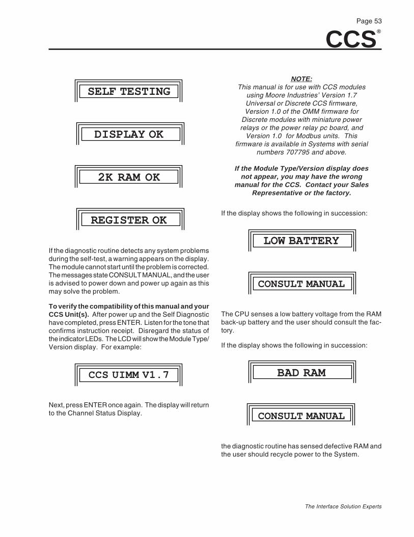
CCS®
Page 53
The Interface Solution Experts
SELF TESTING
DISPLAY OK
2K RAM OK
REGISTER OK
If the diagnostic routine detects any system problemsduring the self-test, a warning appears on the display.The module cannot start until the problem is corrected.The messages state CONSULT MANUAL, and the useris advised to power down and power up again as thismay solve the problem.
To verify the compatibility of this manual and yourCCS Unit(s). After power up and the Self Diagnostichave completed, press ENTER. Listen for the tone thatconfirms instruction receipt. Disregard the status ofthe indicator LEDs. The LCD will show the Module Type/Version display. For example:
CCS UIMM V1.7
Next, press ENTER once again. The display will returnto the Channel Status Display.
NOTE:This manual is for use with CCS modules
using Moore Industries’ Version 1.7Universal or Discrete CCS firmware,Version 1.0 of the OMM firmware for
Discrete modules with miniature powerrelays or the power relay pc board, and
Version 1.0 for Modbus units. Thisfirmware is available in Systems with serial
numbers 707795 and above.
If the Module Type/Version display doesnot appear, you may have the wrong
manual for the CCS. Contact your SalesRepresentative or the factory.
If the display shows the following in succession:
LOW BATTERY
CONSULT MANUAL
The CPU senses a low battery voltage from the RAMback-up battery and the user should consult the fac-tory.
If the display shows the following in succession:
BAD RAM
CONSULT MANUAL
the diagnostic routine has sensed defective RAM andthe user should recycle power to the System.
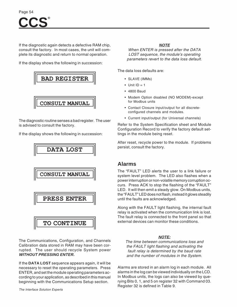
CCS®
Page 54
The Interface Solution Experts
If the diagnostic again detects a defective RAM chip,consult the factory. In most cases, the unit will com-plete its diagnostic and return to normal operation.
If the display shows the following in succession:
BAD REGISTER
CONSULT MANUAL
The diagnostic routine senses a bad register. The useris advised to consult the factory.
If the display shows the following in succession:
DATA LOST
CONSULT MANUAL
PRESS ENTER
TO CONTINUE
The Communications, Configuration, and ChannelsCalibration data stored in RAM may have been cor-rupted. The user should recycle System powerWITHOUT PRESSING ENTER.
If the DATA LOST sequence appears again, it will benecessary to reset the operating parameters. PressENTER, and set the module operating parameters ac-cording to your application, as described in this manualbeginning with the Communications Setup section.
NOTEWhen ENTER is pressed after the DATALOST sequence, the module’s operating
parameters revert to the data loss default.
The data loss defaults are:
• SLAVE (IMMs)
• Unit ID = 1
• 4800 Baud
• Modem Option disabled (NO MODEM)-exceptfor Modbus units
• Contact Closure input/output for all discrete-configured channels and modules.
• Current input/output (for Universal channels)
Refer to the System Specification sheet and ModuleConfiguration Record to verify the factory default set-tings in the module being reset.
After reset, recycle power to the module. If problemspersist, consult the factory.
AlarmsThe “FAULT” LED alerts the user to a link failure orsystem level problem. The LED also flashes when apower interruption or non-volatile memory corruption oc-curs. Press ACK to stop the flashing of the “FAULT”LED. It will then emit a steady glow. On Modbus units,the “FAULT” LED does not flash, instead it glows steadilyuntil the faults are acknowledged.
Along with the FAULT light flashing, the internal faultrelay is activated when the communication link is lost.The fault relay is connected to the front panel so thatexternal devices can monitor these conditions.
NOTE:The time between communications loss andthe FAULT light flashing and activating thefault relay is determined by the baud rate
and the number of modules in the System.
Alarms are stored in an alarm log in each module. Allalarms in the log can be viewed individually on the LCD.In Modbus units, the logs can also be viewed by que-rying Bits 0, 1, and 5 on register 32 with Command 03.Register 32 is defined in Table 9.

CCS®
Page 55
The Interface Solution Experts
Bit # Read Write Command Description
0 RD 03 Communication error (checksum/CRC, cleared when read?)
1 RD 03 Power was OFF
2 RD 03
3 RD 03
4 RD 03
5 RD 03 Configuration data lost
6 RD 03
7 03
8 WR 06 Acknowledge fault conditions (Fault LED is glowing steadily. Set bit toacknowledge)
9 WR 06 Clear all alarms (Set bit to clear)
10 06
11 06
12 06
13 06
14 06
15 06
Note: Communication error is defined as five consecutive CRC errors.
Table 9. Defining Register 32
Once an alarm is displayed, it can be erased from thelog. The same is true for the entire log; it can be clearedand allowed to log future alarms. Modbus units do awrite command 06 on Bit 9 of register 32 to clear allalarms.
Alarms are numbered in the log in the order of theiroccurrence. The first alarm is number “01”. The sec-ond alarm is number “02”. This process is continuedup to the tenth alarm.
When the eleventh alarm occurs, the previous tenth iserased, and succeeding alarms are logged as number10. Modbus equipped units can log up to 99 alarmsbut only 10 can be viewed. Multiple faults can be viewedon the front panel as they occur.
The display has a two digit field that identifies thenumber of each alarm presently stored in the log.
The display shows 10 alarm conditions, in order of theiroccurrence. If ten or fewer alarms have occurred sincethe last time the log was cleared, they can be viewedindividually and are numbered 01 through 10. Shouldmore than 10 alarms be logged, the display shows thefirst nine individually, and the last alarm registered isthe tenth.
Modbus units log up to 99 alarm conditions. Multiplefaults can be logged as they occur and viewed from thefront panel. However, only 10 faults can be viewed.For example, if the CCS has logged 23 alarm condi-tions, then the log will reflect alarms 1-9 and number23. Alarm 23 must be cleared to read Alarm 22 andeach successive alarm must be cleared to read theprevious one in the series. Reading holding register32 will not indicate multiple occurences of the samefault condition.
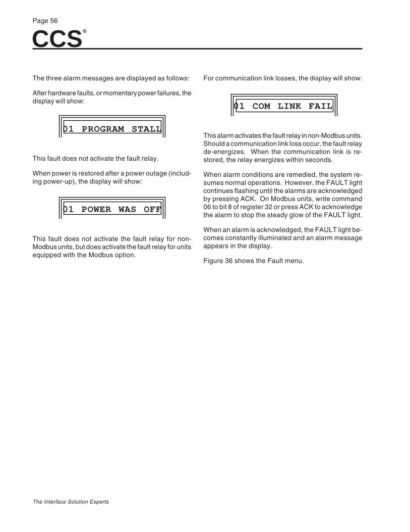
CCS®
Page 56
The Interface Solution Experts
The three alarm messages are displayed as follows:
After hardware faults, or momentary power failures, thedisplay will show:
01 PROGRAM STALL
This fault does not activate the fault relay.
When power is restored after a power outage (includ-ing power-up), the display will show:
01 POWER WAS OFF
This fault does not activate the fault relay for non-Modbus units, but does activate the fault relay for unitsequipped with the Modbus option.
For communication link losses, the display will show:
01 COM LINK FAIL
This alarm activates the fault relay in non-Modbus units.Should a communication link loss occur, the fault relayde-energizes. When the communication link is re-stored, the relay energizes within seconds.
When alarm conditions are remedied, the system re-sumes normal operations. However, the FAULT lightcontinues flashing until the alarms are acknowledgedby pressing ACK. On Modbus units, write command06 to bit 8 of register 32 or press ACK to acknowledgethe alarm to stop the steady glow of the FAULT light.
When an alarm is acknowledged, the FAULT light be-comes constantly illuminated and an alarm messageappears in the display.
Figure 36 shows the Fault menu.
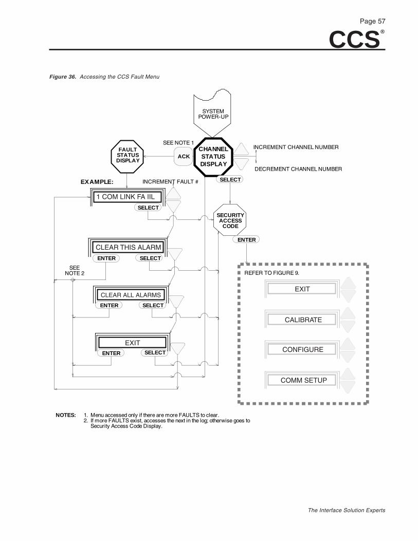
CCS®
Page 57
The Interface Solution Experts
FAULTSTATUSDISPLAY
ACK
SYSTEMPOWER-UP
CHANNELSTATUSDISPLAY
SECURITYACCESS
CODE
INCREMENT CHANNEL NUMBER
DECREMENT CHANNEL NUMBER
SEE NOTE 1
EXAMPLE: INCREMENT FAULT #
SEENOTE 2
1. Menu accessed only if there are more FAULTS to clear.2. If more FAULTS exist, accesses the next in the log; otherwise goes to Security Access Code Display.
NOTES:
ENTER SELECT
SELECT
SELECT
ENTER SELECT
ENTER SELECT
ENTER
REFER TO FIGURE 9.
1 COM LINK FA IIL
CLEAR THIS ALARM
CLEAR ALL ALARMS
EXIT
EXIT
CALIBRATE
CONFIGURE
COMM SETUP
Figure 36. Accessing the CCS Fault Menu

CCS®
Page 58
The Interface Solution Experts
Customer SupportMoore Industries is recognized as the industry leaderin delivering top quality to its customers in productsand services. We perform a battery of stringent qualityasurance checks on every unit we ship. If any MooreIndustries product fails to perform up to rated specifi-cations, call us for help. Our highly skilled staff of trainedtechnicians and engineers pride themselves on theirability to provide timely, accurate, and practical answersto your process instrumentation questions. Factoryphone numbers are on the back cover.
If problems involve a particular CCS, there are severalpieces of information you can gather before you callthe factory that will help our staff get you answers moreefficiently. When you call, please have:
• The model number of the unit in question.
• The serial number of the unit in question.
• The job number (if available).
• The purchase order under which the unit wasshipped (if available).

CCS®
Page 59
The Interface Solution Experts
Index
A
Accessories 7DIN-Style Power Supply, DPS-1200 7Link-to-Fiber Module, LFM 7Redundant Communication Link Module, RLM 7Supply Switching Module, SSM 7
alarms 54Fault Menu 57Messages 56Register 32 54, 55
B
baud rate 27Bench Check–Modbus Units 17
Connection Drawing 18Procedure 17Unit Slave IDs 19
Bench Check–Non-Modbus Units 13equipment 13Example 17Procedure 16SetupSlave IMMs 16
C
CALIBRATE (see also Channel Calibration) 31Caution 1CC OPT 30CC/RELAY 30Channel Calibration 31
Analog IMM Channels 33ENTER FULL 33ENTER ZERO 33NO OPTION 33
Invert output 7, 31NO OPTION 31Set current or voltage 31Set default values 31Universal OMM Channels 33
CALIBRATE FULL 35CALIBRATE ZERO 35DEFAULT TO LAST 35ENTER ZERO 35ENTER FULL 35ENTER DEFAULT 35EXIT 35
Channel Configuration (see Configure Channels)Channel Status Display, example 16Commands
#01 22#02 22#03 22#05 22#06 22#15 22Force Multiple Coils 22Force Single Coil 22Read Coil Status 22Read Input Status 22
Communications Setup 7, 24Baud rate 27COMM SETUP 26Exiting 28Master/Slave 26Menu 12Modem Option 28Set parameters 26Unit ID 27
Compatibility 3, 6Configuration Jumpers 8
Setting IMM Configuration Jumpers 10Setting OMM Configuration Jumpers 11
CONFIGURE 30configure channels 28, 30
CONFIGURE 30CC OPT 30CC/RELAY 30CURRENT OPT 30Exiting 30Parameters 29
Connecting (see also wiring connections)IMM 42OMM 42
Contact closure 45Converting Outputs 30CURRENT OPT 30Current or voltage, setting 31Customer Support 58
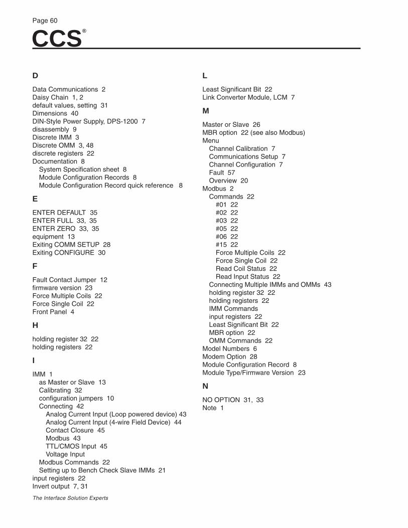
CCS®
Page 60
The Interface Solution Experts
D
Data Communications 2Daisy Chain 1, 2default values, setting 31Dimensions 40DIN-Style Power Supply, DPS-1200 7disassembly 9Discrete IMM 3Discrete OMM 3, 48discrete registers 22Documentation 8
System Specification sheet 8Module Configuration Records 8Module Configuration Record quick reference 8
E
ENTER DEFAULT 35ENTER FULL 33, 35ENTER ZERO 33, 35equipment 13Exiting COMM SETUP 28Exiting CONFIGURE 30
F
Fault Contact Jumper 12firmware version 23Force Multiple Coils 22Force Single Coil 22Front Panel 4
H
holding register 32 22holding registers 22
I
IMM 1as Master or Slave 13Calibrating 32configuration jumpers 10Connecting 42
Analog Current Input (Loop powered device) 43Analog Current Input (4-wire Field Device) 44Contact Closure 45Modbus 43TTL/CMOS Input 45Voltage Input
Modbus Commands 22Setting up to Bench Check Slave IMMs 21
input registers 22Invert output 7, 31
L
Least Significant Bit 22Link Converter Module, LCM 7
M
Master or Slave 26MBR option 22 (see also Modbus)Menu
Channel Calibration 7Communications Setup 7Channel Configuration 7Fault 57Overview 20
Modbus 2Commands 22
#01 22#02 22#03 22#05 22#06 22#15 22Force Multiple Coils 22Force Single Coil 22Read Coil Status 22Read Input Status 22
Connecting Multiple IMMs and OMMs 43holding register 32 22holding registers 22IMM Commandsinput registers 22Least Significant Bit 22MBR option 22OMM Commands 22
Model Numbers 6Modem Option 28Module Configuration Record 8Module Type/Firmware Version 23
N
NO OPTION 31, 33Note 1
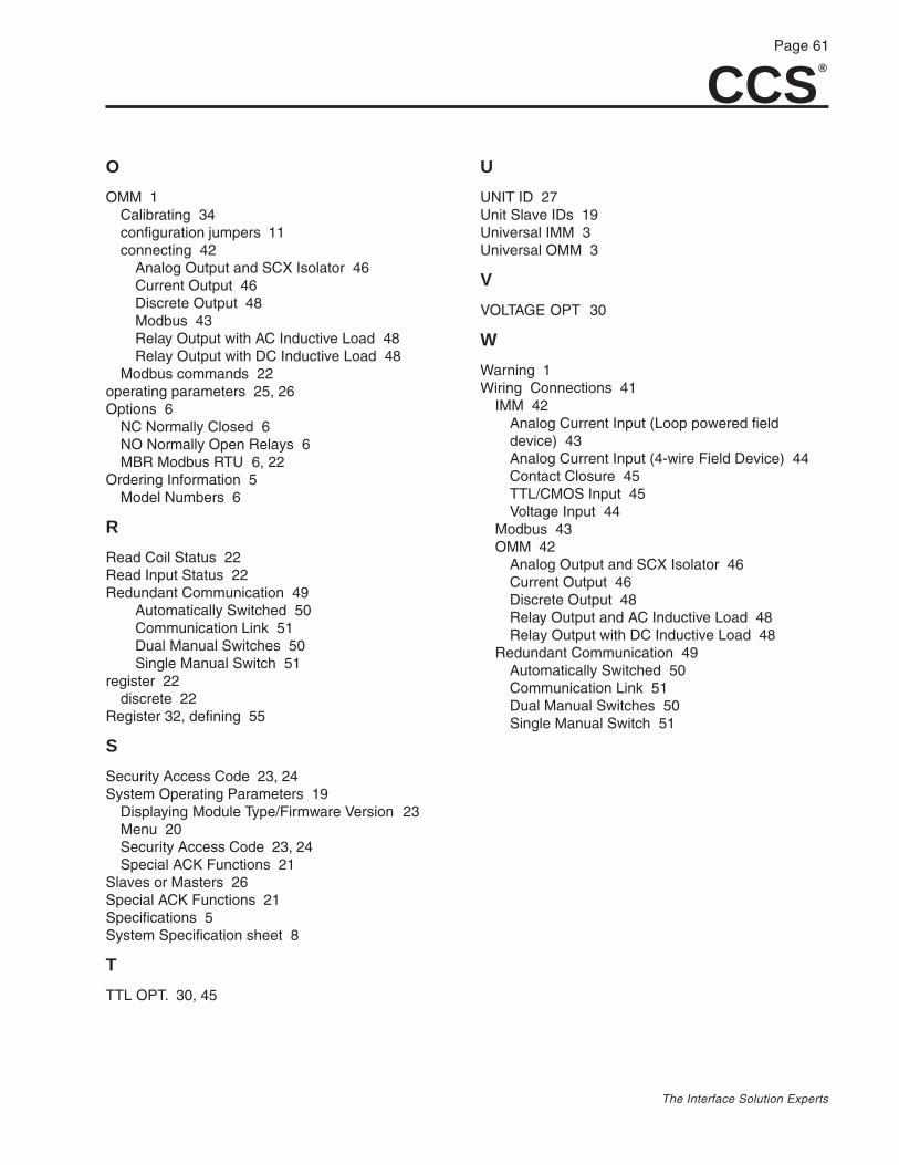
CCS®
Page 61
The Interface Solution Experts
O
OMM 1Calibrating 34configuration jumpers 11connecting 42
Analog Output and SCX Isolator 46Current Output 46Discrete Output 48Modbus 43Relay Output with AC Inductive Load 48Relay Output with DC Inductive Load 48
Modbus commands 22operating parameters 25, 26Options 6
NC Normally Closed 6NO Normally Open Relays 6MBR Modbus RTU 6, 22
Ordering Information 5Model Numbers 6
R
Read Coil Status 22Read Input Status 22Redundant Communication 49
Automatically Switched 50Communication Link 51Dual Manual Switches 50Single Manual Switch 51
register 22discrete 22
Register 32, defining 55
S
Security Access Code 23, 24System Operating Parameters 19
Displaying Module Type/Firmware Version 23Menu 20Security Access Code 23, 24Special ACK Functions 21
Slaves or Masters 26Special ACK Functions 21Specifications 5System Specification sheet 8
T
TTL OPT. 30, 45
U
UNIT ID 27Unit Slave IDs 19Universal IMM 3Universal OMM 3
V
VOLTAGE OPT 30
W
Warning 1Wiring Connections 41
IMM 42Analog Current Input (Loop powered fielddevice) 43Analog Current Input (4-wire Field Device) 44Contact Closure 45TTL/CMOS Input 45Voltage Input 44
Modbus 43OMM 42
Analog Output and SCX Isolator 46Current Output 46Discrete Output 48Relay Output and AC Inductive Load 48Relay Output with DC Inductive Load 48
Redundant Communication 49Automatically Switched 50Communication Link 51Dual Manual Switches 50Single Manual Switch 51

CCS®
Page 62
The Interface Solution Experts

To return equipment to Moore Industries for repair, follow these four steps:
1. Call Moore Industries and request a Returned Material Authorization (RMA) number.
Warranty Repair –If you are unsure if your unit is still under warranty, we can use the unit’s serial numberto verify the warranty status for you over the phone. Be sure to include the RMAnumber on all documentation.
Non-Warranty Repair –If your unit is out of warranty, be prepared to give us a Purchase Order number whenyou call. In most cases, we will be able to quote you the repair costs at that time.The repair price you are quoted will be a “Not To Exceed” price, which means that theactual repair costs may be less than the quote. Be sure to include the RMA number onall documentation.
2. Provide us with the following documentation:
a) A note listing the symptoms that indicate the unit needs repairb) Complete shipping information for return of the equipment after repair
c) The name and phone number of the person to contact if questions arise at the factory
3. Use sufficient packing material and carefully pack the equipment in a sturdy shippingcontainer.
4. Ship the equipment to the Moore Industries location nearest you.
The returned equipment will be inspected and tested at the factory. A Moore Industriesrepresentative will contact the person designated on your documentation if more information isneeded. The repaired equipment, or its replacement, will be returned to you in accordance withthe shipping instructions furnished in your documentation.
WARRANTY DISCLAIMERTHE COMPANY MAKES NO EXPRESS, IMPLIED OR STATUTORY WARRAN-TIES (INCLUDING ANY WARRANTY OF MERCHANTABILITY OR OF FITNESSFOR A PARTICULAR PURPOSE) WITH RESPECT TO ANY GOODS OR SER-VICES SOLD BY THE COMPANY. THE COMPANY DISCLAIMS ALL WARRAN-TIES ARISING FROM ANY COURSE OF DEALING OR TRADE USAGE, ANDANY BUYER OF GOODS OR SERVICES FROM THE COMPANY ACKNOWL-EDGES THAT THERE ARE NO WARRANTIES IMPLIED BY CUSTOM ORUSAGE IN THE TRADE OF THE BUYER AND OF THE COMPANY, AND THATANY PRIOR DEALINGS OF THE BUYER WITH THE COMPANY DO NOT IM-PLY THAT THE COMPANY WARRANTS THE GOODS OR SERVICES IN ANYWAY.
ANY BUYER OF GOODS OR SERVICES FROM THE COMPANY AGREESWITH THE COMPANY THAT THE SOLE AND EXCLUSIVE REMEDIES FORBREACH OF ANY WARRANTY CONCERNING THE GOODS OR SERVICESSHALL BE FOR THE COMPANY, AT ITS OPTION, TO REPAIR OR REPLACETHE GOODS OR SERVICES OR REFUND THE PURCHASE PRICE. THECOMPANY SHALL IN NO EVENT BE LIABLE FOR ANY CONSEQUENTIAL ORINCIDENTAL DAMAGES EVEN IF THE COMPANY FAILS IN ANY ATTEMPTTO REMEDY DEFECTS IN THE GOODS OR SERVICES , BUT IN SUCH CASETHE BUYER SHALL BE ENTITLED TO NO MORE THAN A REFUND OF ALLMONIES PAID TO THE COMPANY BY THE BUYER FOR PURCHASE OF THEGOODS OR SERVICES.
RETURN PROCEDURES
ANY CAUSE OF ACTION FOR BREACH OF ANY WARRANTY BY THECOMPANY SHALL BE BARRED UNLESS THE COMPANY RECEIVESFROM THE BUYER A WRITTEN NOTICE OF THE ALLEGED DEFECT ORBREACH WITHIN TEN DAYS FROM THE EARLIEST DATE ON WHICH THEBUYER COULD REASONABLY HAVE DISCOVERED THE ALLEGED DE-FECT OR BREACH, AND NO ACTION FOR THE BREACH OF ANY WAR-RANTY SHALL BE COMMENCED BY THE BUYER ANY LATER THANTWELVE MONTHS FROM THE EARLIEST DATE ON WHICH THE BUYERCOULD REASONABLY HAVE DISCOVERED THE ALLEGED DEFECT ORBREACH.
RETURN POLICYFor a period of thirty-six (36) months from the date of shipment, and undernormal conditions of use and service, Moore Industries ("The Company") willat its option replace, repair or refund the purchase price for any of its manu-factured products found, upon return to the Company (transportation chargesprepaid and otherwise in accordance with the return procedures establishedby The Company), to be defective in material or workmanship. This policyextends to the original Buyer only and not to Buyer's customers or the usersof Buyer's products, unless Buyer is an engineering contractor in which casethe policy shall extend to Buyer's immediate customer only. This policy shallnot apply if the product has been subject to alteration, misuse, accident, ne-glect or improper application, installation, or operation. THE COMPANYSHALL IN NO EVENT BE LIABLE FOR ANY INCIDENTAL OR CONSE-QUENTIAL DAMAGES.
Specifications and Information subject to change without notice.© 2005 Moore Industries-International, Inc.
United States • [email protected]: (818) 894-7111 • FAX: (818) 891-2816
Australia • [email protected]: (02) 8536-7200 • FAX: (02) 9525-7296
Belgium • [email protected]: 03/448.10.18 • FAX: 03/440.17.97
The Netherlands • [email protected]: (0)344-617971 • FAX: (0)344-615920
China • [email protected]: 86-21-62491499 • FAX: 86-21-62490635
United Kingdom • [email protected]: 01293 514488 • FAX: 01293 536852