Embed Size (px)
Citation preview

STZFunctional Safety Dual Input
Smart HART® Temperature Transmitter
Mounting choices include field enclosures with display, no display compact connection heads and a high-density DIN-style housing. STZ-DIN model with -AIS option is shown with blue terminals.
*High-accuracy measurements are achieved by using a 4-wire, 1000 ohm platinum RTD with a span of 100°F (50°F minimum) calibrated in our sensor-matching calibration bath.
October 2017
Page 1
DescriptionPart of Moore Industries’ FS Functional Safety Series, the SIL 2 and SIL 3 capable STZ Functional Safety Dual Input Smart HART® Temperature Transmitters for your SIS (Safety Instrumented System) configures quickly and easily to accept a single or dual input from a wide array of sensors and analog devices located in hazardous and non-hazardous areas: • 14 RTD Types
• 9 Thermocouple Types
• Resistance and Potentiometer Devices
• Direct Millivolt Sources These 2-wire (loop-powered) transmitters provide an isolated and linear 4-20mA output proportional to the input. This signal is ready for direct interface with HART or non-HART based Safety System, DCS, PLC and other computer-based SCADA systems. FMEDA (Failure Mode Effects and Diagnostic Analysis) reports are available with the required safety data to ensure that the STZ meets the requirements of each Safety Instrumented Function (SIF).
Features• exida certified to IEC 61508:2010. Certified by exida
to IEC 61508 for systematic integrity up to SIL 3 and for random integrity up to SIL 2. This means that an STZ is approved for single use in Safety Instrumented Systems (SIS) up to SIL 2 and in a redundant architecture (1oo2, 2oo3, etc.) up to SIL 3.
• Comprehensive FMEDA certified safety data. Upon request, exida-certified FMEDA data is available for a functional safety practitioner to use in determining the STZ’s applicability in specific safety-related applications.
• AIS option allows direct connection of sensors located in hazardous locations without the requirement of an intrinsically safe barrier. This option has blue terminals, DIN housing only.
• Dual sensor input for Backup and Failover Protection, Average and Differential measurement and Low or High Select.
• Device Intelligence including Sensor Drift and Corrosion Detection, Smart Range Alarms, High-availability option, and Input Simulation capability.
• HART 7 compliant with exception-based reporting and dynamic variable mapping.
• HART Access Control. To prevent unauthorized or accidental reconfiguration of the STZ while it’s performing it’s safety function, it has an added security feature to allow users to set HART communication into a Read Only or Off mode.
• Input-to-output analog accuracy of up to ±0.014°C (±0.025°F)* is the absolute best in the industry.
• 20-bit input resolution delivers exceptional digital accuracy of ±0.1°C (±0.18°F) with all Pt RTDs or up to ±0.05°C (±0.09°F)* for Pt1000 RTDs.
• HART & DTM Programmable with user-oriented basic configuration for fast and accurate setup. HART configurable via any HART handheld configurator or HART compatible host. Additionally program or monitor with any FDT compliant host or program, such as PACTware, utilizing our DTM.
235-710-22C© 2017 Moore Industries-International, Inc.
All product names are registered trademarks of their respective companies. HART® is a registered trademark of FieldComm Group.
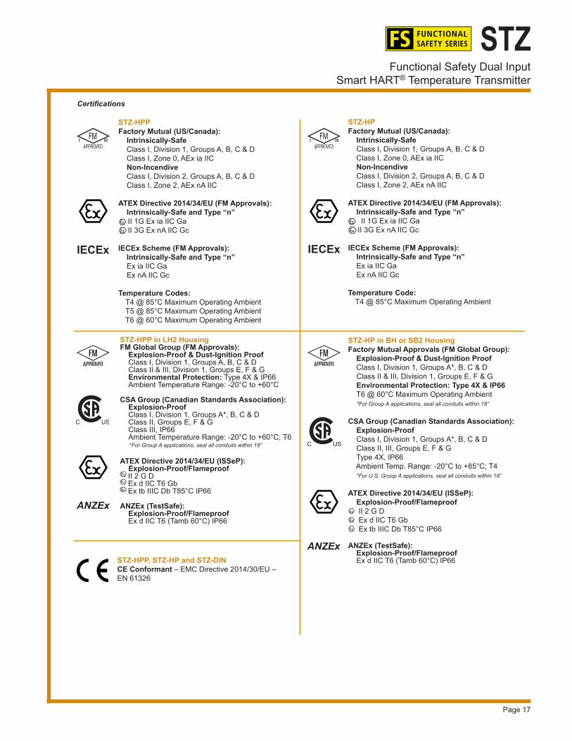
Certifications (see Page 17 for details)
IEC61508

Page 2
STZFunctional Safety Dual InputSmart HART® Temperature Transmitter
SISLogic Solver
STZ
Sensor 1(Primary)
Sensor Failover/Backup Enabled
Sensor 2(Secondary)
Reactor
Logic Solver(Single Loop
or Safety PLC)
Sensor
Dual Sensor Input(Backup/Failover
Protection)
Final Element
Figure 2. The STZ can be applied as the temperature sensor/transmitter in a typical SIS loop.
Certified to IEC 61508 The STZ has been certified, by exida to IEC61508 for systematic integrity up to SIL 3 and for single use in Safety Instrumented Systems (SIS) up to SIL 2. It has been designed and developed in strict compliance with IEC 61508 standards to provide the highest level of system integrity and reliability. Internal diagnostics provide protection against dangerous failures during operation. Approval by exida means that you can have confidence when selecting the STZ that is the right instrument for your safety needs. You don’t have to worry about documenting and tracking Proven-In-Use data as you would with non-IEC 61508-approved instruments.
Dual Sensor Input Gives You Expanded Measurement Capability and Protection for your Safety SystemsWith Dual Input sensors, the SIL 2 and SIL 3 capable STZ has advanced features that give you far more control over temperature measurements (see Figure 1) in your traditional loops and Safety Instrumented Systems (SIS). Each sensor is individually selectable and programmable.
• Backup and Fail-Over Protection allows either of the sensors or inputs to be designated as the primary measurement, with the secondary input acting as the backup sensor in case of primary sensor failure.
• Average and Differential Measurement allows you to average the two input measurements or select the differential (A-B or B-A) or absolute differential between the two inputs.
• High-Select and Low-Select Feature enables the transmitter to continuously monitor two separate inputs and designate either the highest or lowest input to represent the analog output.
• Dynamic Variable Mapping permits the user to assign either input or the calculated result of inputs to any of the four HART variables (PV, SV, TV or QV) that can be read by any HART-compatible host system.
Figure 1. Temperature is often a critical measurement in reactors, especially processes with the potential for thermal runaways due to exothermic reactions. Utilizing the failover/backup feature with dual sensor input on the STZ can help your Safety Instrumented System (SIS) mitigate potentially dangerous situations.

Page 3
STZFunctional Safety Dual Input
Smart HART® Temperature Transmitter
STZ Status
READOUTOR ALARM
4-WireRTD
Broken RTDWire #2
Sensor Error Message
PC ConfigurationSoftware
(partial window shown)
Upscale orDownscale Driveon Sensor Failure
In the Figure 4 (below), the actual sensor curve is used in place of the ideal RTD curve between 20°C and 27°C. This provides incredible precision over a limited portion of span, while measuring the remainder of the span with the STZ’s usual outstanding accuracy.
Program 128-Point Custom Curves Beyond trimming curves, you can create up to four custom curves and apply them to any available device variables in the STZ. You can program several properties for each curve including:
• The number of active points in the custom curve• Units of the inbound data to be processed by the
curve (X values)• Units of the outbound data that is the result of
processing by the curve (Y values)
Precise Linearization and RJC The STZ uses an advanced linearization method to minimize the conformance error. Its Reference (Cold) Junction Compensation techniques produce stable readings even in fluctuating ambient temperature conditions. For non-linear inputs, you can create custom linearization curves using our DTM with any FDT-compliant host.
Total Sensor Diagnostics These transmitters perform continuous sensor diagnostics (Figure 3). This patented Moore Industries feature can save you from costly lost production time and hours of troubleshooting. If the sensor breaks or otherwise stops sending a signal during operation, the transmitter sends the output upscale or downscale to warn of trouble, and provides a HART digital error message that can be read by a HART communicator, computer-based system or PC. If the sensor being utilized is a RTD, the STZ instantly displays the type and location of the error.
Trims to Respond to Specific Sensor Curve Segments Most transmitters’ zero and full values can be calibrated to measure a specific range within a sensor’s overall curve capability. However, for even greater measurement accuracy, our transmitter trim capabilities go much further. The STZ can be trimmed with two data points within the selected zero and full measurement range. This advantage allows a complete process range to be monitored, while placing measurement emphasis on a specific segment of the range most critical to the process.
Figure 3. Patented Total Sensor Diagnostics saves troubleshooting time.
Lower(Zero)Range
Upper(Full)
Range
Ideal RTD Curve(Used by Default)
ActualSensorCurve
10098
10
°C
Upper TrimPoint #2
Lower TrimPoint #1
27
20
Captured20°C-27°C
Figure 4. The STZ can be set to measure the segment most critical to the process.

Page 4
STZFunctional Safety Dual InputSmart HART® Temperature Transmitter
4-20mA Analog with Digital HARTSuperimposed
HARTCommunicator
(Secondary Master)
–
–
++
Functional SafetySmart HART
Temperature TransmitterHART Slave Device
(STZ in HPP Enclosure shown)
SISLogic Solver
ORBPCS
HARTPrimary Masteror Non-HART
Communicating Device
PowerSupply
NOTE:The HART Communicator or PC with Smart HARTInterface Cable may be connected at any terminationpoint on the signal loop. The HART Communicatorand the signal loop must have between a 250and 1100 ohm load for proper communications.
HART Master/Slave StructureTo implement two-way communications between the transmitter and the device configuring or receiving its information, the transmitter operates in a HART Master/Slave structure. The STZ is a Slave (or Slaves in a multidrop network). There can be two Masters per system: a Primary Master and a Secondary Master. In the majority of applications, the Primary Master is a HART-based host or control system and the Second- ary Master is typically a hand-held configurator. Operating in HART’s Poll/Response (Normal) Mode, the HART Master polls the transmitter two times per second to access the current process variable status, send setup data to the transmitter, or remotely view its identification, configuration and diagnostic data.
Device Intelligence for Smarter Monitoring and ControlThe advanced features we have built into the STZ give you the ability to simulate sensor input before you commit to installation, alert you to faulty sensor conditions and prevent unwanted alarms which help increase your process uptime and availability.
• Sensor Drift and Corrosion Detection checks and alerts you when the sensor is drifting out of your preset range or when sensor resistance levels drastically change, which can be an early indication of sensor failure.
• Smart Range Alarms offer four HART alarms set to any input or calculated input that detect when the variable is within or outside user preset limits.
• High Availability Option enables the user to select how the AO behaves when there is an input failure or out-of-range value detected by the transmitter. This prevents nuisance alarms on startups or batch process shutdowns.
• Input Simulation Capability allows the user to manually input a direct or calculated value, in effect simulating a real input to test the AO or any HART diagnostic and range alarms.
Set Up with HART Host, Communicator or FDT-Compliant Host or Program (No HART Modem Required) The STZ Functional Safety Smart HART Transmitters are HART and DTM programmable. They can be programmed quickly and easily and interrogated at anytime from anywhere on the 4-20mA loop (see Figure 5). You can use a standard hand-held HART Communicator, a HART compatible host, or you can program or monitor with any FDT compliant host or program such as PACTware utilizing our DTM.
• HART Communications Security Feature sets HART communications to Read Only Mode (STZ responds to HART commands to access device variables and diagnostic status but does not allow changes to the unit’s configuration) or Off Mode (no HART messages are sent from the STZ and all HART message sent to the unit are ignored). This security feature prevents unauthorized or accidental reconfiguration of the STZ while it is performing safety functions.
• Program Input Type and Range—Full, zero and input type values are all programmable.
Figure 5. From any termination point on the 4-20mA loop, you can view, test and change the transmitter’s operating parameters using a HART Communicator or from a PC using our DTM with PACTware or other FDT compliant program (a HART modem is not required for PC setup).

Page 5
STZFunctional Safety Dual Input
Smart HART® Temperature Transmitter
Large, configurable
display shows input(s), output
or toggles between both
The HART address is displayed for
easily identifying the unit's place
on the loop
Incredible accuracydisplayed with up to three decimal places
Alphanumeric characters display standardor custom engineering units or (when an error occurs), the location and typeof problem
• Adjust Sensor Trim Offset—Set an offset to compensate for measurement errors that are caused when a temperature sensor is not performing to its rated curve specifications.
• Set Damping Time—Eliminate imprecise readings caused by noise and other insignificant process fluctuations by setting a damping time between 0-60 seconds.
• View Real-Time Process Values—View the existing process value (in the appropriate engineering unit), zero and full range values, actual output current and output current as a percentage of output span.
• Choose Sensor Failure Mode—If the input is lost, you have the choice of the output going upscale (to 23.6mA), downscale (to 3.6mA) or holding its last value. For safety applications, the STZ default is to fail low.
• Select Device Identification and Data—Tag number (Long Tags up to 32 characters supported in HART 7), configuration date, unit location code (16 characters), a message (32 characters) and polling address (0-63) are selectable.
• Fix Output Current (Loop Test)—To assist in calibrating your system, the transmitter’s current output can be fixed to a known value so you can check it against the value being read by your receiving device.
Non-Volatile Memory If power to the transmitter is lost, the unit resumes normal operation using the parameters that were configured, upon reapplication of power. Point-to-Point Loops Deliver Analog Simplicity with Remote Programmability In the majority of applications, the STZ is installed on a point-to-point 4-20mA process loop like a regular analog transmitter (see Figure 5). A HART Communicator, HART-based system or PC is used to configure and view the transmitter’s operating parameters and diagnostic data from any point on the loop.
Figure 6. The STZ features a standard process display that shows input(s), output or toggles intermittently between both.
Easy-to-Read, Customizable Display The STZ transmitter comes standard with a large display that features easy-to-read alphanumeric characters. Set the display to show input status, output status or toggle between both. It can even be custom-scaled to display an engineering unit of your choice (see Figure 6). STZ Device Description (DD) Moore Industries’ Device Description (DD) is the device-specific programming information that is loaded into a standard HART Communicator or Host. It allows access to all of the unit’s programming functions except the custom linearization table function.
How to Determine if Your HART Communicator Has a STZ Device Description Hand-held HART Communicators typically feature a list of companies in a DD library. The letters “STZ” will appear under Moore Industries if you have the proper DD installed. If the handheld does not have the proper DD, contact the nearest regional sales and service office. Also Programs with the Generic HART DD Even if your communicator is not up to date, most of the important programming features can be accessed without the STZ DD by using the “Generic” HART DD available on HART Communicators. Or you can order the unit factory-configured by Moore Industries.
Set Up (Continued)

Page 6
STZFunctional Safety Dual InputSmart HART® Temperature Transmitter
FREE PACTware Configuration Software with Versatile Programming Options Download PACTware software for FREE from our website which allows you to set up all transmitter settings utilizing our DTM easy to use pull down menus.
No HART Modem Required—Using the Moore Industries PC Interface Cable, the transmitter is programmed via a communication port located on the front of the unit. A HART modem is not required to connect the PC to the transmitter.
Remote PC Programming With a HART Modem With PACTware—For programming from any access point on the loop, a HART-to-USB Smart Interface Cable (modem) can be purchased separately (see Ordering Information for details) to access the STZ programming options. The HART modem can also be connected directly to the transmitter.
Once a setup is created, it can be downloaded to multiple transmitters. Just a few of the time saving and performance enhancing features include:
Quick and Intuitive Setup
Set Up Safeguards—It is nearly impossible to make incompatible configuration selections.Quick Transmitter/Configuration Upload/Download—PACTware offers one button uploading and downloading of transmitter configuration.Toolbar for Frequently Used Commands— A conveniently located toolbar provides quick access to often used configuration functions.Real-Time Process Readout—The process measurement and the communication status between the transmitter and PACTware can be viewed in a one-page window.Precise Digital Output Trimming—This essentially eliminates the impact of measurement errors introduced by inaccurate readout devices.Selectable Under Range, Over Range and Sensor Failure Values—By setting different default values for each condition, you can distinguish between the failure modes when they occur.Store, E-mail, Download and Print Files—The configuration record you’ve created may be downloaded to any number of transmitters, saved, e-mailed, or printed for record keeping.

Page 7
STZFunctional Safety Dual Input
Smart HART® Temperature Transmitter
Hazardous AreaClass I, Div 1/Zone 0, 1 Safe Area
or Class I, Div 2/Zone 2
4-20mA w/HART
Logic SolverSen1
Sen2
SMART HART TEMPERATURE TRANSMITTER
DUAL SENSOR
COM
STZ Associated ApparatusA traditional Intrinsically Safe (IS) system installation requires a barrier or associated apparatus interface between the temperature sensor located in the hazardous area and the monitoring equipment located in the safe area. Its function is to limit the energy to the hazardous area such that, even under a fault condition, there cannot be enough electrical or thermal energy released from the safe area into the hazardous area to ignite an explosive atmosphere.
One method of protection is to use temperature sen-sor Zener Diode barriers which are simple passive devices comprised of Zener diodes, resistors and fuses that serve to limit the voltage, current, and power available to the hazardous area sensor or device. This design requires the use of a dedicated IS earth ground connection maintained at less than 1Ω, which can sometimes be hard to locate or guarantee.
Another protection method is to install Isolated barriers for your temperature sensors located in hazardous areas. These are active devices that incorporate galvanic isolation, thus eliminating the requirement for a very low impedance and high integrity earth ground. However, these barriers require auxiliary operating power and cost more than passive Zener barriers.
The disadvantage of these separate IS barriers is the installation and maintenance costs. Many of these costs can be drastically reduced if an associated ap-paratus like the STZ-DIN with the -AIS option is used.
Associated I.S. Input WiringFigure 7. The STZ-DIN with -AIS option is an associated appara-tus, which includes a built-in IS barrier in its front end, allowing the connected sensors to be located in a hazardous area.
Since the STZ-DIN is an associated apparatus, which includes a built-in IS barrier in its front end, there is no need for the additional cost of a barrier, cabinet space, a high integrity clean ground connection, separate power supply or custom vendor backplane. This dramatically reduces the cost of purchase, installation and long-term maintenance.
The STZ-DIN with the -AIS Option is an associated apparatus which is suitable for installation in Non-Hazardous or Class I Division 2/Zone 2 areas with direct connection to temperature sensors located in Class I Div 1/Zone 0/1 locations.
See the white paper: “Associated Apparatus: The Safe and Most Affordable IS Solution” for a more detailed overview of Associated IS Apparatus.
Figure 8. The STZ-DIN with -AIS option Entity Parameters.
Entity Parameters PRG (Terminals 1, 2, 3, 4, 5)
Temperature Class:T4 Tamb = -40°C to +85°C
All field wiring shall berated for +90°C
GasGroup
Uo (Voc)V
Io (Ioc)mA
PomW
Co (Ca)μF
Lo (La)/RomH/Ohm
Lo (La)mH
IIC (A,B)
IIB (C)
IIA (D)
7.94
7.94
7.94
71.43
71.43
71.43
141.8
141.8
141.8
8.32
27.87
55.74
250.74
999.92
99.92
6.96
1002.97
2005.95

Page 8
STZFunctional Safety Dual InputSmart HART® Temperature Transmitter
SpecificationsHART
Specifications Address Range: 0-63 (1-63 are for multidrop loops) Transmission Speed: 1200 bps Character Format: 1 Start Bit - 8 Data Bits - 1 Odd Parity Bit - 1 Stop Bit Input Accuracy: Refer to Table 1 Output Range: 4-20mA Analog Output Accuracy: 3µA (0.019% of 4-20mA Span) Overall Accuracy: The overall accuracy of the unit is the combined input and output accuracy. It includes the combined effects of linearity, hysteresis, repeatability and adjustment resolution. It does not include ambient temperature effect. For T/C input only, add the Reference Junction Compensation error Reference (Cold) Junction Compensation: ±0.25°C (±0.45°F); DIN ±0.45°C (±0.81°F) Stability: Refer to Table 2 Isolation: STZ HPP, DIN and DIN –RF: 500Vrms input-to-output continuous; will withstand a 1350Vac dielectric strength test for one minute with no breakdown input-to-output to case; STZ HP: 500Vrms input-to-output continuous, will withstand a 500Vac dielectric strength test for one minute with no breakdown input-to-output to case. Response (Rise) Time: 100msec maximum for the output to change from 10% to 90% for an input step change of 0% to 100% Step Response Time: 460msec (single),650msec (dual) typical from the time an input is applied until the output reaches 90% of its final value
Ripple: 10mVp-p measured across a 250 ohm load resistor at frequencies up to 120Hz Input Over-voltage Protection: ±3Vdc peak to peak, maximum Digital Input Filter: User-programmable; 50/60Hz Power Supply Effect: ±0.002% of span per 1V change Load Effect: Negligible within specified power limits Load Capability: (500 ohms@24V)
Burnout Protection: User-programmable, Upscale 23.6mA; Downscale 3.6mA; preset value or hold-last output Output Current Limiting: User-programmable, 3.6 to 4.0mA and 20 to 23.6mA for input under/over range; 24mA, maximum (hardware limit) T/C Input Impedance: 40Mohms, nominal RTD & Ohms Excitation: 250 microamps, ±10% RTD Lead Wire Resistance Maximum: RTD resistance + 2X lead wire resistance < 4000 ohms; Damping: User set; 0-60 seconds Resolution: Input, 20-bit; Output, 16-bit Power Supply Requirement: 12-30Vdc for I.S. version; 12-42Vdc for standard version
Performance (Continued)
0.024ASupply Voltage - 12V = Ohms
Performance
Type: LCD; Top Row, 10mm (0.4 in) high black digits on a reflective background; Bottom Row, 6mm (0.225 in) high digits on a reflective background; Two-digit HART address indicator Format: Two rows of five alphanumeric characters Decimal Points: Allowed decimal places: Auto, 1, 2 or 3 Range: -99999 to 99999 Minimum Display Span: 1.00 Operating Range: -40°C to +85°C (-40°F to +185°F) Storage Range: -40°C to +85°C (-40°F to +185°F) Relative Humidity: 0-95%, non-condensing Ambient Temperature Effect: See Table 3 Effect on Reference (Cold) Junction Compensation: ±0.005% per °C change of ambient temperature Startup Time: The system output reaches 90% of its value based on input in less than 5 seconds after power up Noise Rejection: Common mode, 100dB@50/60Hz; Normal Mode: Refer to Table 4 RFI/EMI Immunity: 20 V/m @ 80-1000 MHz, 1kHz AM for STZ HP and STZ DIN and 10 V/m @ 80-1000 MHz, 1kHz AM for STZ HPP when tested according to IEC61000-4-3
STZ DIN: 221g (7.9 oz) STZ HPP: 91g (3.2 oz) STZ HPP in LH2: 644g (22.9 oz) STZ HP: 182g (6.4 oz) STZ HP in BH: 1.4kg (50.2 oz) STZ HP in SB: 3.2kg (113 oz)
Display
Ambient Temperature
Weight

Page 9
STZFunctional Safety Dual Input
Smart HART® Temperature Transmitter
100
200
300
400
500
1000
100
200
400
500
1000
100
120
9.035
0-4000 ohms
n/a
n/a
n/a
n/a
n/a
n/a
n/a
n/a
n/a
n/a
-200 to 850°C -328 to 1562°F
-100 to 650°C -148 to 1202°F
-200 to 510°C -328 to 950°F -80 to 320°C -112 to 608°F -50 to 250°C -58 to 482°F 0-4000 ohms
0-100%
-180 to 760°C -292 to 1400°F
-150 to 1370°C -238 to 2498°F
-170 to 1000°C -274 to 1832°F
-170 to 400°C -274 to 752°F
0 to 1760°C 32 to 3200°F
0 to 1760°C 32 to 3200°F
400 to 1820°C 752 to 3308°F
-130 to 1300°C -202 to 2372°F
0 to 2300°C 32 to 4172°F
-50 to 1000mV
Table 1. Input and Accuracy Table (RTD, T/C, Ohm, mV and Potentiometer Input Model)
-240 to 960°C -400 to 1760°F
-150 to 720°C -238 to 1328°F
-240 to 580°C -400 to 1076°F -100 to 360°C -148 to 680°F -65 to 280°C -85 to 536°F 0-4095 ohms
0-100%
-210 to 770°C -346 to 1418°F
-270 to 1390°C -454 to 2534°F
-270 to 1013°C
-454 to 1855.4°F
-270 to 407°C -454 to 764.6°F
-50 to 1786°C
-58 to 3246.8°F
-50 to 1786°C -58 to 3246.8°F
200 to 1836°C
392 to 3336.8°F
-270 to 1316°C -454 to 2400.8°F
0 to 2338°C
32 to 4240.4°F
-50 to 1000mV
Direct Resistance
Potentiometer J
K E T R S B N C
DC
Input Type α∗ Ohms Conformance Range
Minimum Span
Input Accuracy
Maximum Range
10°C
(18°F)
10 ohms
10%
35°C 63°F
40°C 72°F
35°C 63°F
35°C 63°F
50°C 90°F
50°C 90°F
75°C 135°F
45°C 81°F
100°C 180°F
4mV
Ohms
Platinum
Nickel
Copper
0.003850
0.003902
0.003916
0.00672
0.00427
n/a
n/a
n/a
n/a
n/a
n/a
n/a
n/a
n/a
n/a
n/a
±0.1°C (±0.18°F)
±0.85°C
(±1.53°F) ±0.4 ohms
±0.1%
±0.25°C
(±0.45°F)
±0.3°C (±0.54°F)
±0.2°C
(±0.36°F)
±0.25°C (±0.45°F)
±0.55°C
(±0.99°F)
±0.55°C (±0.99°F)
±0.75°C
(±1.35°F)
±0.4°C (±0.72°F)
±0.8°C
(±1.44°F)
30 microvolts
T/C
RTD
Sensor-to-Transmitter Matching
Up to ±0.014°C (±0.025°F) system accuracy*.
*High-accuracy measurements are achieved by using a 4-wire, 1000 ohm platinum RTD with a span of 100°F (50°F minimum) calibrated in our sensor-matching calibration bath. See page 9 or contact our factory for additional information.
mV
125, 250, 500, 1k, 2k, 4k ohms

Page 10
STZFunctional Safety Dual InputSmart HART® Temperature Transmitter
Complete Temperature AssembliesFree yourself from the hassle of looking around for pieces and parts by ordering a complete assembly. To complement our high-quality transmitters, we carry complete lines of RTDs, thermocouples, thermowells, connection heads and fittings. Get the quality you need and the options you require with the ease of just one ordering number! For the best accuracy, have your transmitter and sensor calibrated together in our sensor-matching calibration bath. See our Ready-to-Install Temperature Transmitter Assemblies data sheets for details. Sensor-to-Transmitter Matching Our sensor matching process starts by immersing the temperature sensor into stabilized temperature baths in our calibration lab. The transmitter captures two points from the sensor and stores them in non-volatile memory. It then uses them to compensate for deviations between a sensor’s stated linearization curve and its actual measurements. Sensor matching provides you with incredible accuracy at an affordable price. Accuracy varies with the sensor, so contact the factory for information on your sensor type.
Table 4. Normal Mode Rejection Ratio Table (RTD, T/C, Ohm, mV and Potentiometer Input Models)
Table 2. Long-Term Stability Table (RTD, T/C, Ohm, mV and Potentiometer Input Model)
5 yrs
0.019
0.104
Stability (% of maximum
span)
T/C, mV
RTD, Ohm, Potentiometer
1 yr
0.08
0.09
Input to Output Input to HART
3 yrs
0.14
0.16
5 yrs
0.18
0.21
1 yr
0.008
0.047
3 yrs
0.015
0.081
Table 3. Ambient Temperature Effects Table (RTD, T/C, Ohm, mV and Potentiometer Input Model)
Sensor Type
RTD
All T/C
T/C: B
Millivolt
Ohm
Analog Accuracy per 1°C (1.8°F)
change in Ambient
0.001% of span (16mA)
0.001% of span (16mA)
0.001% of span (16mA)
0.001% of span (16mA)
0.001% of span (16mA)
Digital Accuracy per 1°C (1.8°F)
change in Ambient
0.003°C
0.0003°C + 0.0015% of reading
0.003°C + 0.0015%
of reading
0.0005mV + 0.0015% of reading
0.002 ohms + 0.0015%
of reading
Sensor Type Max. p-p Voltage Injection for 70dB at 50/60Hz
T/C ET/C J, K, N, CT/C T, R, S, B100 ohm Pt RTD200 ohm Pt RTD300, 400, 500, 1000 ohm Pt RTD1000 ohm Pt RTD120 ohm Ni RTD9.03 ohm Cu RTDResistance 4Kohm/mV 1000mVResistance 2Kohm/mV 500mVResistance 1Kohm/mV 250mVResistance 500ohm/mV 125mVResistance 250ohm/mV 62.5mVResistance 125ohm/mV 31.25mV
120mV60mV30mV
120mV200mV400mV800mV200mV30mV
800mV400mV200mV120mV50mV30mV

Page 11
STZFunctional Safety Dual Input
Smart HART® Temperature Transmitter
Versatile Housing, Enclosure and Mounting Choices
Model Features Dimensions
STZ in LH2 Aluminum Connection Head Field-MountEnclosure
STZ in HPP Encapsulated Housing
• Small size and protected, encapsulated electronics make this model ideal for integrating into industrial machinery, machine tools, facility monitoring systems and similar production and process equipment.
• For retrofit applications, standard diameter and mounting hole dimensions allow easy integration into installed thermowell and remote-mounted connection heads.
• Compact, lightweight connection head mounts right on the thermowell/sensor assembly, or in a convenient remote location from the sensor.
• Encapsulated electronics resist the harmful effects of moisture and humidity that enter though the conduit connections.
• Explosion-proof/Flameproof, NEMA 4X, IP66 rated.
Page 13
Page 13
Page 14
Page 14
Page 14
• The -AIS Option allows direct connection of sensors from hazardous areas
• Only 25mm (1-inch) wide, this compact model is perfect for mounting in a control room, high-density instrument cabinet or
field-mounted enclosure.
• Mounting bracket easily snaps on and off of 35mm Top Hat DIN-rails and standard relay tracks.
STZ in DIN Rail Mount Housing
STZ in HP Hockey-Puck Housing with Display
• Mounts on a surface, G-type or top hat rails and on relay track when on site display is needed in a control room, cabinet or enclosure.
• Replacement transmitter installs in a Moore Industries BH or SB housings.
STZ in BH Aluminum Field-Mount Enclosure
• Perfect choice when reliable field protection and on site indication are required.
• Modular transmitter electronics can be rotated 360 degrees to accomodate any viewing angle and easily removed without disturbing the enclosure or sensor assembly.
• Explosion-proof/Flameproof, NEMA 4X, IP66 rated.
STZ in SB 316 Stainless Steel Field-Mount Enclosure
Page 12
STZFunctional Safety Dual InputSmart HART® Temperature Transmitter
Ordering Information
STZ Functional Safety Dual Input Smart HART Temperature Transmitter
PRG Programmable with standard HART communicator or HART compatible host; program or monitor with any FDT compliant host or program, such as PACTware, utilizing our DTM. RTD 2-, 3-, 4-Wire Platinum, Copper, Nickel Thermocouple (J, K, E, T, R, S, B, N, C) 0-4000 ohms -50-1000mV (see Table 1 for additional information)
Unit Input Output Power Options Housing
4-20MA Scalable to narrower ranges
12-42DC* 12-30DC Intrinsically- Safe (I.S.) applications
* Non-incendive (Class 1 Div 2, Zone 2) by default
None HPP Hockey-puck housing for mounting in standard connection heads LH2NS(*) or (‡) Aluminum Explosion-proof/Flameproof connection head with two entry ports: ½-inch NPT cable and process–black metal cover LH2MS(*) or (‡) Aluminum Explosion-proof/Flameproof connection head with two entry ports: M20 cable and ½-inch NPT process–black metal cover
* Either A or E suffix (comes supplied with 2” pipe mount hardware) A suffix indicates ANZEx/TestSafe (Ex d) Flameproof approvals (i.e. LH2NSA) E suffix indicates ATEX (Ex d and tD) Flameproof approvals (i.e. LH2NSE) ‡ P suffix indicates enclosure comes equipped with base plate and U-bolts for mounting on a 2-inch pipe (i.e. LH2NSP)
See LH datasheet for additional information.
To order, specify: Unit / Input / Output / Power / [Housing] Model Number Example: STZ / PRG / 4-20MA / 12-30DC / [LH2NS]
STZ Functional Safety Dual Input Smart HART Temperature Transmitter
PRG Programmable with standard HART communicator or HART compatible host; program or monitor with any FDT compliant host or program, such as PACTware, utilizing our DTM. RTD 2-, 3-, 4-Wire Platinum, Copper, Nickel Thermocouple (J, K, E, T, R, S, B, N, C) 0-4000 ohms -50-1000mV (see Table 1 for additional information)
Unit Input Output Power Housing
4-20MA Scalable to narrower ranges
12-42DC DIN DIN-style aluminum housing mounts on 35mm Top Hat (EN50022) rails
FLB Flange bracket with top/bottom mounting holes
To order, specify: Unit / Input / Output / Power / [Housing] Model Number Example: STZ / PRG / 4-20MA / 12-42DC /-AIS [DIN]
Field Mount Unit
DIN-Style Mount UnitOptions
-AIS Includes IS barrier protection allowing direct connection of sensors located in Class I Div 1 & Zone 0/1 hazardous locations - includes blue input terminals

Page 13
STZFunctional Safety Dual Input
Smart HART® Temperature Transmitter
Ordering Information
Unit Input Output Power Options Housing
STZ Functional Safety Dual Input Smart HART Temperature Transmitter
PRG Programmable with standard HART communicator or HART compatible host; program or monitor with any FDT compliant host or program, such as PACTware, utilizing our DTM. RTD 2-, 3-, 4-Wire Platinum, Copper, Nickel Thermocouple (J, K, E, T, R, S, B, N, C) 0-4000 ohms -50-1000mV (see Table 1 in Section 7 for additional information)
4-20MA Scalable to narrower ranges
12-42DC* 12-30DC Intrinsically- Safe (I.S.) applications
*Non-Incendive (Class 1 Div 2, Zone 2) by default
None
HP Hockey puck housing and spring clips DN Snap-in mounting for HP case on TS-32 DIN-rail FL Mounting flanges on HP for relay track or screw mounting FLD Mounting flanges on HP for 3½” relay track mounting BH2NG (*) or (‡) Aluminum Explosion-proof/Flameproof enclosure with two 1/2-inch NPT entry ports and a glass cover BH2TG (*) or (‡) Aluminum Explosion-proof/Flameproof enclosure with two 3/4-inch NPT entry ports and a glass cover BH2MG (*) or (‡) Aluminum Explosion-proof/Flameproof enclosure with two M20 x 1.5 NPT entry ports and a glass cover BH3NG (*) or (‡) Aluminum Explosion-proof/Flameproof enclosure with three 1/2-inch NPT entry ports BH3TG (*) or (‡) Aluminum Explosion-proof/Flameproof enclosure with two 3/4-inch side-entry NPT ports, one 1/2” bottom port, and a glass cover BH3MG (*) or (‡) Aluminum Explosion-proof/Flameproof enclosure with two, M20 x 1.5 side-entry ports, one 1/2” bottom-entry port, and a glass cover SB2NG (*) or (‡) 316 Stainless Steel 2-Hub, Explosion-proof/Flameproof enclosure with two, ½-inch NPT entry ports and a glass cover SB2MG (*) or (‡) 316 Stainless Steel 2-Hub, Explosion-proof/Flameproof enclosure with two, M20 x 1.5 entry ports and a glass cover * Either A or E suffix A suffix indicates ANZEx/TestSafe (Ex d) Flameproof approvals (i.e. BH2MGA) E suffix indicates ATEX (Ex d and tD) Flameproof approvals (i.e. BH2MGE) ‡ P suffix indicates enclosure comes equipped with base plate and U-bolts for mounting on a 2-inch pipe (i.e. BH2NGP)
See BH and SB datasheets for additional information.
Additional PartsThe communications cables must be purchased separately: P/N 804-030-26–Non-Isolated Fuse Protected USB Communication Cable (required by IECEx and ATEX for products installed in Intrinsically- Safe areas)
P/N 803-040-26–Non-Isolated Serial Configuration Cable for 2-Wire Instruments
P/N 804-021-26–HART-to-USB Smart Interface Cable with HART Modem.
To order, specify: Unit / Input / Output / Power / [Housing]Model Number Example: STZ / PRG / 4-20MA / 12-42DC / [BH2NGP]
Field Mount Unit With Display
Page 14
STZFunctional Safety Dual InputSmart HART® Temperature Transmitter
72mm DIA.(2.85 in)
86mm(3.42 in)
InstrumentMounting
Holes33mm
(1.30 in)
I.D. 62mm x 19mm Deep(2.44 in X 0.75 in Deep)
Ground
Not Used
Not Used
M4.0 x 0.7(x4 Plcs)
30mm(1.20 in)
93mm(3.68 in)
89mm(3.50 in)
9mm(0.35 in)
ConduitEntry Port
TOP VIEW
FRONT VIEW BOTTOM VIEW
2-INCH PIPE MOUNTING HARDWARE
SIDE VIEW
Process Connection1/2-in NPT
(N and M models)or G½ (BSP)(C models)
61mm(2.40 in)
10-32Mounting
Holes (x2)
51mm(2.01 in)
85mm(3.36 in)
MetalTag
32mm1.27in
48mm1.90in
33mm1.30in
51mm2.04in
23°
4-40 ThreadsInserts x 2 PLCS
51mm2.04in
33mm1.30in
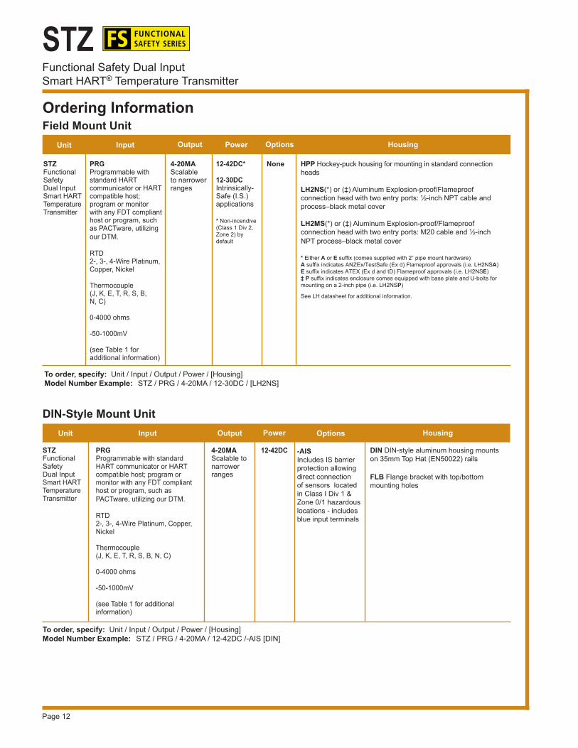
Figure 9. Dimensions for the STZ in the HPP hockey-puck housing.
Figure 10. Dimensions for the STZ in the LH2 connection head.
Note: Make sure to calibrate and bench check the instruments prior to installation. Also, install all instruments in their intended application and on their rail before making any electrical connections. Allow enough room for pivoting instruments vertically on the rail for removal in applications involving multiple banks of STZ transmitters.

Page 15
STZFunctional Safety Dual Input
Smart HART® Temperature Transmitter
134.6mm(5.30 in)
102.6mm(4.04 in)
SMART HART TEMPERATURE TRANSMITTER
DUAL SENSOR
28mm(1.11 in)
+PS -PS 1 2 3 4
68mm(2.68 in)
GND
1/2 NPT
102mm(4.02 in)
84mm(3.31 in)
68mm(2.68 in)
64mm(2.52 in)
10mm(0.38 in)
124mm(4.88 in)
25mm(1.00 in)
102mm(4.02 in)
119mm(4.69 in)
76mm(2.99 in)57mm
(2.24 in)22mm
(0.87 in)
SIDE VIEW
TOP VIEW
ADDRADDRADDRADDR
STZ
62mm(2.45 in)
75mm(2.97 in)
63.5mm(2.50 in)
ADDRADDADDRR
STZ
Figure 11. Dimensions for the STZ in BH field-mount enclosure.
Figure 12. Dimensions for the STZ in an aluminum DIN housing Figure 13. Dimensions for the STZ in an aluminum HP display housing.
Page 16
STZFunctional Safety Dual InputSmart HART® Temperature Transmitter
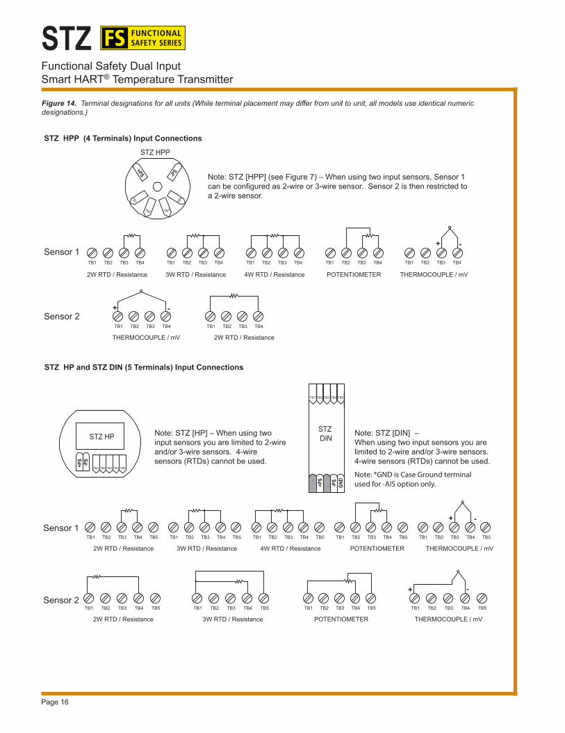
Figure 14. Terminal designations for all units (While terminal placement may differ from unit to unit, all models use identical numeric designations.)
TB1 TB2 TB3 TB4
2W RTD / Resistance 3W RTD / Resistance
TB1 TB2 TB3 TB4
4W RTD / Resistance
TB1 TB2 TB3 TB4
POTENTIOMETER
TB1 TB2 TB3 TB4
2W RTD / Resistance
TB1 TB2 TB3 TB4
POTENTIOMETER
TB1 TB2 TB3 TB4 TB5
POTENTIOMETER
TB1 TB2 TB3 TB4 TB5
4W RTD / Resistance
TB1 TB2 TB3 TB4 TB5
3W RTD / Resistance
TB1 TB2 TB3 TB4 TB5
2W RTD / Resistance
TB1 TB2 TB3 TB4 TB5
THERMOCOUPLE / mV
TB1 TB2 TB3 TB4 TB5
+ -
TB1 TB2 TB3 TB4
THERMOCOUPLE / mV
+ -
TB1 TB2 TB3 TB4 TB5
2W RTD / Resistance
THERMOCOUPLE / mV
TB1 TB2 TB3 TB4
+ -
TB1 TB2 TB3 TB4 TB5
THERMOCOUPLE / mV
+ -
Sensor 1
Sensor 1
Sensor 2
Sensor 2
TB1 TB2 TB3 TB4 TB5
3W RTD / Resistance
-PS
+PS
-PS
+PS
STZ HPP
STZ DINSTZ HP
TB1 TB2 TB3 TB4 TB5
TB2 TB3
TB4TB1
-PS
+PS
TB1 TB2 TB3 TB4 TB5
STZ HPP (4 Terminals) Input Connections
STZ HP and STZ DIN (5 Terminals) Input Connections
Note: STZ [HPP] (see Figure 7) – When using two input sensors, Sensor 1 can be configured as 2-wire or 3-wire sensor. Sensor 2 is then restricted to a 2-wire sensor.
Note: STZ [DIN] – When using two input sensors you are limited to 2-wire and/or 3-wire sensors. 4-wire sensors (RTDs) cannot be used.
Note: STZ [HP] – When using two input sensors you are limited to 2-wire and/or 3-wire sensors. 4-wire sensors (RTDs) cannot be used.
GND
Note: *GND is Case Ground terminal used for -AIS option only.
Page 17
STZFunctional Safety Dual Input
Smart HART® Temperature Transmitter
STZ-HP in BH or SB2 Housing Factory Mutual Approvals (FM Global Group): Explosion-Proof & Dust-Ignition Proof Class I, Division 1, Groups A*, B, C & D Class II & III, Division 1, Groups E, F & G Environmental Protection: Type 4X & IP66 T6 @ 60°C Maximum Operating Ambient *For Group A applications, seal all conduits within 18”
CSA Group (Canadian Standards Association): Explosion-Proof Class I, Division 1, Groups A*, B, C & D Class II, III, Groups E, F & G Type 4X, IP66 Ambient Temp. Range: -20°C to +85°C; T4 *For U.S. Group A applications, seal all conduits within 18”
ATEX Directive 2014/34/EU (ISSeP): Explosion-Proof/Flameproof
II 2 G D Ex d IIC T6 Gb Ex tb IIIC Db T85°C IP66
ANZEx (TestSafe): Explosion-Proof/Flameproof Ex d IIC T6 (Tamb 60°C) IP66
STZ-HPP in LH2 HousingFM Global Group (FM Approvals): Explosion-Proof & Dust-Ignition Proof Class I, Division 1, Groups A, B, C & D Class II & III, Division 1, Groups E, F & G Environmental Protection: Type 4X & IP66 Ambient Temperature Range: -20°C to +60°C
CSA Group (Canadian Standards Association): Explosion-Proof Class I, Division 1, Groups A*, B, C & D Class II, Groups E, F & G Class III, IP66 Ambient Temperature Range: -20°C to +60°C; T6 *For Group A applications, seal all conduits within 18”
ATEX Directive 2014/34/EU (ISSeP): Explosion-Proof/Flameproof II 2 G D
Ex d IIC T6 GbEx tb IIIC Db T85°C IP66
ANZEx (TestSafe): Explosion-Proof/Flameproof Ex d IIC T6 (Tamb 60°C) IP66
Certifications
IECEx
STZ-HPP, STZ-HP and STZ-DINCE Conformant – EMC Directive 2014/30/EU – EN 61326
STZ-HPP Factory Mutual (US/Canada): Intrinsically-Safe Class I, Division 1, Groups A, B, C & D Class I, Zone 0, AEx ia IIC Non-Incendive Class I, Division 2, Groups A, B, C & D Class I, Zone 2, AEx nA IIC ATEX Directive 2014/34/EU (FM Approvals): Intrinsically-Safe and Type “n” II 1G Ex ia IIC Ga II 3G Ex nA IIC Gc
IECEx Scheme (FM Approvals): Intrinsically-Safe and Type “n” Ex ia IIC Ga Ex nA IIC Gc
Temperature Codes: T4 @ 85°C Maximum Operating Ambient T5 @ 85°C Maximum Operating Ambient T6 @ 60°C Maximum Operating Ambient
IECEx
STZ-HPFactory Mutual (US/Canada): Intrinsically-Safe Class I, Division 1, Groups A, B, C & D Class I, Zone 0, AEx ia IIC Non-Incendive Class I, Division 2, Groups A, B, C & D Class I, Zone 2, AEx nA IIC ATEX Directive 2014/34/EU (FM Approvals): Intrinsically-Safe and Type “n”
II 1G Ex ia IIC Ga II 3G Ex nA IIC Gc
IECEx Scheme (FM Approvals): Intrinsically-Safe and Type “n” Ex ia IIC Ga Ex nA IIC Gc
Temperature Code: T4 @ 85°C Maximum Operating Ambient

Page 18
STZFunctional Safety Dual InputSmart HART® Temperature Transmitter
Certifications
STZ-DIN (-AIS Option only)
IECEx
Factory Mutual – FM Approvals – US/Canada Associated Apparatus providing Intrinsically Safe connections to: Class I, II, III, Division 1, Groups A-G Class I, Zone 0, [AEx ia] IIC Non-Incendive/Non-sparking Class I, Division 2, Groups A-D providing I.S. connections to Class I, II, & III, Division 1, Groups A-G ATEX Directive 2014/34/EU (FM Approvals): Associated Intrinsically-Safe Non-Sparking with Intrinsically Safe Outputs II (1) G [Ex ia Ga] IIC II 3 (1) G Ex nA [ia Ga] IIC Gc
IECEx Scheme (FM Approvals): Associated Intrinsically-Safe Non-Sparking with Intrinsically Safe Outputs [Ex ia Ga] IIC Ex nA [ia Ga] IIC Gc Temperature Code: T4 @ 85°C Maximum Operating Ambient
STZ-DINFactory Mutual (US/Canada): Non-Incendive Class I, Division 2, Groups A, B, C & D
Temperature Code: T4 @ 85°C Maximum Operating Ambient
The exida® certified SIL 2/3 capable STA Safety Trip Alarm performs as a logic solver and acts on potentially hazardous process conditions in your SIS. The STA models accept a signal input from transmitters, temperature sensors and a wide array of other monitor-ing and control instruments.
Features:■ Dual process alarms, one fault alarm■ Site-programmable with password protection■ Combined alarm trip and transmitter■ Large 5-digit process and status readout
More Functional Safety Product Solutions
STA Functional Safety Trip Alarm

Page 19
STZFunctional Safety Dual Input
Smart HART® Temperature Transmitter
The exida® certified SIL 2 capable SRM Safety Relay Module provides a high level of availability for safety-critical applications within your SIS. The SRM is a relay repeater that accepts a single contact closure input from a logic solver, such as the STA Safety Trip Alarm, and provides three relay outputs per alarm input. This allowsyou to simply and cost effectively add additional alarm contacts to your safety system.
Features■ Visual front panel diagnostic information■ Internal input snubbing diode■ Fuse protected input power and relays
These exida® certified SIL 2/3 capable 2-wire and 4-wire Isolators and Splitter provide isolation and signal splitting for your SIS needs. These units protect and enhance loops and also pass valuable HART® data from the field transmitter to host systems and vice-versa. They isolate your SIS from your Basic Process Control System or monitoring system so disconnections or failures to these secondary systems don’t affect your safety system.
Features■ 1500Vrms isolating capability■ Built-in HART pass-through technology■ SST Splitter provides two fully isolated outputs■ SST includes Transmitter Excitation
More Functional Safety Product Solutions
SSX and SST Functional Safety Isolators and Splitter
SRM Functional Safety Relay Module

Page 20
STZFunctional Safety Dual InputSmart HART® Temperature Transmitter
United States • [email protected]: (818) 894-7111 • FAX: (818) 891-2816
Australia • [email protected]: (02) 8536-7200 • FAX: (02) 9525-7296
Belgium • [email protected]: 03/448.10.18 • FAX: 03/440.17.97The Netherlands • [email protected]
Tel: (0)344-617971 • FAX: (0)344-615920
China • [email protected]: 86-21-62491499 • FAX: 86-21-62490635
United Kingdom • [email protected]: 01293 514488 • FAX: 01293 536852
Specifications and information subject to change without notice.
More Functional Safety Product Solutions
The SFY Functional Safety SIL 2/3 capable Frequency-to-DC Transmitter with Display monitors frequency, pe-riod, high or low pulse width, and contact closure signals and converts the input signal to a proportional, input-to-output isolated 4-20mA output ready for direct interface with a Safety System, readout instrument, recorder, PLC, DCS, SCADA system.
Features:■ Versatile frequency range input choices■ Programmable moving average filter■ Quick and easy configuration from your PC
The SIL 3 capable Moore Industries’ SLD Safety Programmable Loop Display features a large integral display that shows real-time process status in mA, percent, or any designated 5-character Engineering Units (EGU). SLD is used in a Safety Instrumented Function to display critical process data at eye level for plant personnel. The SLD is a non-interference device that can be taken out of the loop with the –LMD option (Loop Maintenance Diode) without affecting the integrity of the SIF.
Features:■ Easy-to-read, customizable display■ 360°, flexible mounting at any angle in nearly any environment■ Low voltage drop allows the SLD to be installed on burdened loops■ Create custom curves or import directly from Excel ■ Can be removed from the loop for maintenance without interrupting your safety function
SFY Functional Safety Frequency-to-DC Transmitter
SLD Functional Safety Programmable Loop Display


![PIH Installation Manual - Moore Industries · 2019-01-29 · PIH User Manual Field Mount Pressure-to-Current Transmitter 123-723 00C January 2018 [2] Moore Industries-International,](https://img.pdfslide.us/doc/110x75/5f372a487a73c57bf450f464/pih-installation-manual-moore-industries-2019-01-29-pih-user-manual-field-mount.jpg)