Embed Size (px)
Citation preview

NET Concentrator System®
Process Control and Distributed I/O
NCS
• Superior 20-bit input and 18-bit output resolution. Matches or exceeds the accuracy of the most precise process transmitters on the market, easily surpassing the specifications claimed by other I/O systems.
• Installs in harsh ambient temperature conditions. An operating range of -40°C to +85°C (-40°F to +185°F) permits installation in locations well outside the capabilities of comparable systems.
• Quick and simple programming. Using the Internet Explorer web browser or Moore Industries’ free Intelligent PC Configuration Software, operating parameters can be viewed, selected, and set in minutes.
• Industry-standard OPC interface. Delivers plug-and-play integration with popular PC-based HMI and SCADA automation software packages.
• Isolation and RFI/EMI protection. Eliminates unpredictable ground loops and protects against the harmful effects of plant electrical “noise”.
• Peer-to-Host and Peer-to-Peer operation. Flexible architecture options provide versatile application possibilities.
• Transmit any distance, over any terrain. Use a twisted wire pair, Ethernet cabling, wireless, fiber optics, or telephone modem data link to overcome rugged, long-distance, normally impassable, and hazardous environments.
• Data logging capabilities. Up to 64,000 points of time-stamped data can be stored and retrieved.
Designed specifically for demanding industrial applications, the NET Concentrator System® (NCS) provides a real-time signal gateway between the field or factory floor and your control strategy.
Complete Monitoring and Control Networks The NCS is the ideal solution when you need to network new and existing “legacy” process sensors, instruments and final control elements with computer-based monitoring and control systems. Universal and modular, it programs to handle a wide range of signal input and control output possibilities:
• Current • Voltage • Discrete • Relay • RTD • Thermocouple • Resistance • Potentiometer
Features
Description
Page 1© 2017 Moore Industries-International, Inc. 288-710-01J
Rugged metal construction delivers superior RFI/EMI protection and stands up to the daily rigors of demanding process and factory automation applications.
November 2017
Figure 1. The NCS links new and existing “legacy” process equipment with DCS, PLC and PC-based HMI/SCADA strategies.
Certifications (see Page 16)
DCS, PLC,or PC with HMI/SCADA(with NET ConcentratorSystemOPC Server)
NET ConcentratorSystem (NCS)
Simultaneous Ethernet and/or Dual MODBUS RTU Networks*
Distributed Field Devices
Process Variable TransmittersTemperature Sensors
Control ValvesDiscrete Devices
Relays
ModuleNumber
ModuleNumber
*Simultaneous Communicationson Separate Physical Data Links
Simultaneous Ethernet and Dual MODBUS RTU (Master/Slave) Communications The NCS comes standard with one Ethernet (MODBUS/TCP) port and dual, independent MODBUS RTU (RS-485) ports. One or both of the MODBUS ports can be configured as MODBUS master ports. This allows the NCS to poll other MODBUS RTU slaves with all of the network polling functions of a typical MODBUS master.

NET Concentrator System® Process Control and Distributed I/O
NCS
Page 2
New Installations and “Legacy” Retrofit Applications
The NET Concentrator System (NCS) is ideal for creating new monitoring and control networks. It is also perfect when you want to leave existing “legacy” sensors, analog instruments and valves in place, yet still take advantage of digital signal transmission. The NCS can be used to send just a few, or hundreds, of process signals between the field and your control system. Industrially-hardened and configurable I/O stations mount throughout a site or in dispersed locations throughout the world to provide cost-effective distributed data acquisition and control.
Save Thousands on Installation CostsThe NCS saves time and money when used in place of hard-wired schemes. Concentrate just a few, or hundreds, of process signals onto a single digital data link. You’ll save the cost of cable, conduit, connection and wire tray costs. You can even use an existing Ethernet network and eliminate the time and expense of creating a new network. The NCS also simplifies overall system design, installation and maintenance.
NET Concentrator System networks are made up of one or more stand-alone I/O stations consisting of one EMM Ethernet/MODBUS Interface Module, combined with Input and/or Output Modules. Any combination of Input and Output Modules may be used within a NET Concentrator System network. The NCS comes standard with one Ethernet (MODBUS/TCP) port and dual MODBUS RTU (RS-485) ports. The system will work in both Peer-to-Host and Peer-to-Peer Systems.
Peer-to-Host SystemsPeer-to-Host Systems provide a cost-effective method to transfer monitoring and control signals to and from a host DCS, PLC or PC-based system. In this architecture, NET Concentrator System stations are distributed along an Ethernet (MODBUS/TCP) network and/or one or two MODBUS RTU serial networks. Once the data is delivered to the host system, third-party HMI or SCADA software packages can be used to create user interface strategies that may include data acquisition, alarm summary and management, data logging and reporting, historical data collection and trending and supervisory control functions. Ethernet (IEEE 802.3) Networks The number of NET Concentrator System (NCS) stations that can be used on an Ethernet (MODBUS/TCP) network is limited only by the architecture of a specific network*. Standard industrial Ethernet switches or hubs are available to interconnect large numbers of NCS stations. Ethernet switches also minimize message collisions, improving determinism in the NCS Ethernet network (Figure 2).
Standard Dual MODBUS RTU Networks When the NCS uses MODBUS RTU (RS-485) for communications, each of the dual MODBUS RTU ports can be programmed to act as a master or slave within a network (each port is configured by the factory as a MODBUS slave port). Up to 32 (without repeaters) NET Concentrator System slave stations and/or third- party slave devices per dual port can be distributed throughout a plant multidropped on the MODBUS RTU data link(s). The NCS will handle up to 64 slave devices if both MODBUS ports are used. Depending on the type of I/O modules used, a station can accommodate as few as four or as many as 128 points**.
System Architecture
System Architectures
Peer-to-Host Systems
Peer-to-Peer Systems
MODBUS Master Systems
System Advantages
Module Types
Ordering Information
Specifications
EMM Ethernet/MODBUS Interface Module
AIM Analog Input Module
AOM Analog Output Module
TIM Temperature Input Module
DIM Discrete Input Module (Contact Closure or Voltage)
ROM Relay Output Module
CPM Concentrator Power Supply Module
Advanced Control and Math Functions
Data Link Options
Installation Dimensions
Agency Certifications
System Accessories
2-4
2-3
4
5
6
7
8
9-15
9
10
11
12-13
14
14
15
10
11
15
16
16
Table of Contents
*Taking into account the physical limitations of Ethernet. Consult the factory for details.
** The number of available channels differs from NCS module to module. See “Ordering Information” on Page 7 for details.
NET Concentrator System®
Process Control and Distributed I/O
NCS
Page 3
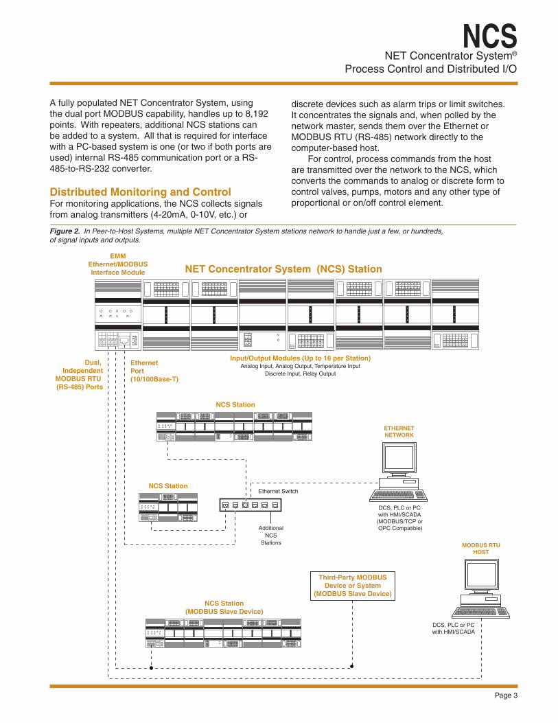
Figure 2. In Peer-to-Host Systems, multiple NET Concentrator System stations network to handle just a few, or hundreds, of signal inputs and outputs.
NET Concentrator System (NCS) Station
DCS, PLC or PC with HMI/SCADA
(MODBUS/TCP or OPC Compatible)
ETHERNETNETWORK
EthernetPort(10/100Base-T)
Dual, Independent
MODBUS RTU (RS-485) Ports
Additional NCS
Stations
Ethernet SwitchNCS Station
NCS Station
NCS Station(MODBUS Slave Device)
Third-Party MODBUSDevice or System
(MODBUS Slave Device)
MODBUS RTUHOST
DCS, PLC or PC with HMI/SCADA
ModuleNumber
ModuleNumber
ModuleNumber
ModuleNumber
ModuleNumber
ModuleNumber
ModuleNumber
Input/Output Modules (Up to 16 per Station)Analog Input, Analog Output, Temperature Input
Discrete Input, Relay Output
EMM Ethernet/MODBUSInterface Module
discrete devices such as alarm trips or limit switches. It concentrates the signals and, when polled by the network master, sends them over the Ethernet or MODBUS RTU (RS-485) network directly to the computer-based host. For control, process commands from the host are transmitted over the network to the NCS, which converts the commands to analog or discrete form to control valves, pumps, motors and any other type of proportional or on/off control element.
A fully populated NET Concentrator System, using the dual port MODBUS capability, handles up to 8,192 points. With repeaters, additional NCS stations can be added to a system. All that is required for interface with a PC-based system is one (or two if both ports are used) internal RS-485 communication port or a RS-485-to-RS-232 converter. Distributed Monitoring and Control For monitoring applications, the NCS collects signals from analog transmitters (4-20mA, 0-10V, etc.) or
NET Concentrator System® Process Control and Distributed I/O
NCS
Page 4
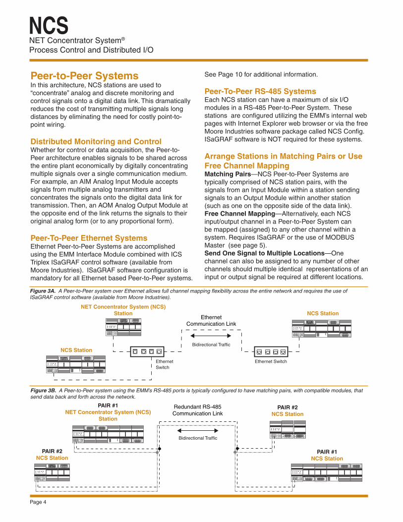
Peer-to-Peer Systems In this architecture, NCS stations are used to “concentrate” analog and discrete monitoring and control signals onto a digital data link. This dramatically reduces the cost of transmitting multiple signals long distances by eliminating the need for costly point-to-point wiring.
Distributed Monitoring and ControlWhether for control or data acquisition, the Peer-to-Peer architecture enables signals to be shared across the entire plant economically by digitally concentrating multiple signals over a single communication medium. For example, an AIM Analog Input Module accepts signals from multiple analog transmitters and concentrates the signals onto the digital data link for transmission. Then, an AOM Analog Output Module at the opposite end of the link returns the signals to their original analog form (or to any proportional form).
Peer-To-Peer Ethernet SystemsEthernet Peer-to-Peer Systems are accomplished using the EMM Interface Module combined with ICS Triplex ISaGRAF control software (available from Moore Industries). ISaGRAF software configuration is mandatory for all Ethernet based Peer-to-Peer systems.
See Page 10 for additional information.
Peer-To-Peer RS-485 SystemsEach NCS station can have a maximum of six I/O modules in a RS-485 Peer-to-Peer System. These stations are configured utilizing the EMM’s internal web pages with Internet Explorer web browser or via the free Moore Industries software package called NCS Config. ISaGRAF software is NOT required for these systems.
Arrange Stations in Matching Pairs or Use Free Channel MappingMatching Pairs—NCS Peer-to-Peer Systems aretypically comprised of NCS station pairs, with thesignals from an Input Module within a station sendingsignals to an Output Module within another station(such as one on the opposite side of the data link).Free Channel Mapping—Alternatively, each NCS input/output channel in a Peer-to-Peer System can be mapped (assigned) to any other channel within a system. Requires ISaGRAF or the use of MODBUS Master (see page 5).Send One Signal to Multiple Locations—One channel can also be assigned to any number of other channels should multiple identical representations of an input or output signal be required at different locations.
Figure 3A. A Peer-to-Peer system over Ethernet allows full channel mapping flexibility across the entire network and requires the use of ISaGRAF control software (available from Moore Industries).
NCS StationNET Concentrator System (NCS)
Station
ModuleNumber
EthernetSwitch
NCS Station
ModuleNumber
EthernetCommunication Link
Ethernet Switch
Bidirectional Traffic
Figure 3B. A Peer-to-Peer system using the EMM’s RS-485 ports is typically configured to have matching pairs, with compatible modules, that send data back and forth across the network.
PAIR #1NCS Station
PAIR #1NET Concentrator System (NCS)
Station
PAIR #2NCS Station
ModuleNumber
Redundant RS-485Communication Link
ModuleNumber
ModuleNumber
ModuleNumber
PAIR #2NCS Station
ModuleNumber
ModuleNumber
Bidirectional Traffic

NET Concentrator System®
Process Control and Distributed I/O
NCS
Page 5
MODBUS Master SystemsThe two RS-485 ports on the EMM Interface Module can act as independent MODBUS RTU slaves, masters, or in Peer-to-Peer mode. The NCS MODBUS Master mode only applies to the MODBUS RTU ports. It is not applicable to the MODBUS/TCP (Ethernet) port.
Simple Setup and ConfigurationConfiguration of MODBUS Master capability is accomplished by using the EMM’s internal web pages with Internet Explorer web browser or via the free Moore Industries software package called NCS Config. Additionally a text file named “Schedule.ini” has to be created and uploaded to the EMM. The Schedule.ini file is a simple text file, created with any text editor such as Notepad, that instructs the NCS where and what data to read/write using the MODBUS RTU RS-485 port(s).
MODBUS Data TransferWith its MODBUS Master capability, the NCS allows:
MODBUS RTU slave data acquisition, dynamic channel mapping, control, and even gateway functions.
Data Acquisition—Any MODBUS RTU slave devicefrom Moore Industries or any other vendor can bepolled by the NCS utilizing either one or both of the two RS-485 ports.Channel Mapping—Read/Write any data to and from any MODBUS RTU device; on either of the EMM’s RS-485 ports. Control—If any connected MODBUS RTU slave device has relay or analog output capability the NCS can write process values down to that device for control or alarming applications.Gateway Functions—Often newer host systems can communicate via MODBUS/TCP over Ethernet but not MODBUS RTU. The MODBUS Master feature allows the EMM to act as a MODBUS/TCP to MODBUS RTU gateway by bi-directionally sharing data between the two different networks.
Figure 4. The built-in MODBUS Master capability allows the NCS to read and write any process variable data points to and from MODBUS RTU slave devices.
Ethernet (10/100Base-T)
NCS Station(MODBUS RTU Master& MODBUS/TCP Slave)
MODBUS/TCPHOST
ModuleNumber Ethernet Switch
COM
HCSREADY
INPUT
+PS -PS 1 2 3 4
TDZ
ADDR
ModuleNumber
TCMTemperature Concentrator
Module
STATUS
TEMPERATURECONCENTRATORMODULE
COM
HMCHART-to-MODBUS
Converter
INPUT
READY
FAULT 1
FAULT 2
HARTMODBUSCONVERTER
COM
microNCS MODBUS RTU Master and Distributed I/O System HCSHART-to-MODBUSGateway
MicroNCSMODBUS RTU I/O System NCS Station
Field TransmitterMODBUS RTU Slave
RS-485MODBUS RTU
RS-485MODBUS RTU
16 InputsAny Combination
RTDThermocouple
ResistanceMillivolts
Inputs/Outputs
Since the NCS supports MODBUS MasterCapability, process data from all field
MODBUS RTU devices can be viewed here.Valves and other equipment can also be
be controlled from here
HART Field Devices
READYSTATUS
NET Concentrator System® Process Control and Distributed I/O
NCS
Page 6
Fast and Simple Set Up—The NET ConcentratorSystem includes a Web server utility that allows configuration and real time viewing of process data via Internet Explorer Web browser over your Intranet (or Internet) from any PC, with proper security password clearance. Alternatively our free Intelligent PC configuration software, NCS Config, can also be used for programming and viewing of real time process data via the Ethernet port.
Standard OPC Server—When installed on a PC, our OPC (OLE for Process Control) data server acts as a centralized location for communicating with local NCS stations and remote
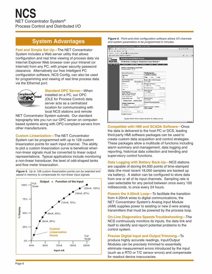
NET Concentrator System subnets. Our standard topography lets you run our OPC server on computer-based systems along with OPC-compliant servers from other manufacturers. Custom Linearization—The NET Concentrator System can be programmed with up to 128 custom linearization points for each input channel. The ability to plot a custom linearization curve is beneficial when non-linear signals must be converted to linear output representations. Typical applications include monitoring a non-linear transducer, the level of odd-shaped tanks and flow meter linearization.
Figure 6. Point-and-click configuration software allows I/O channels and system parameters to be programmed in minutes. System Advantages
Figure 5. Up to 128 custom linearization points can be selected and saved in memory to compensate for non-linear input signals.
8mA 12mA 16mA 20mA4mA
Input mA
0%
25%
50%
75%
100%
% D
isp
lay
FullScale
FullScale
(6mA, 35%)
(8mA, 50%)
(12mA, 70%)
(16mA, 87%)
(20mA, 100%)
Output = Function of the Input
Compatible with HMI and SCADA Software—Once the data is delivered to the host PC or DCS, leading third-party HMI software packages can be used to create custom data acquisition and control strategies. These packages allow a multitude of functions including alarm summary and management, data logging and reporting, historical data collection and trending and supervisory control functions. Data Logging with Battery Back-Up—NCS stations are capable of storing 64,000 points of time-stamped data (the most recent 18,000 samples are backed up via battery). A station can be configured to store data from one or all of its input channels. Sampling rate is user-selectable for any period between once every 100 milliseconds, to once every 24 hours. Powers the 4-20mA Loop—To facilitate the transition from 4-20mA wires to digital communications, the NET Concentrator System’s Analog Input Module (AIM) supplies power to existing or new 2-wire analog transmitters that must be powered by the process loop.
On-Line Diagnostics Speeds Troubleshooting—The NCS continuously monitors its inputs, the data link and itself to identify and report potential problems to the control system.
Precise Digital Input and Output Trimming—To produce highly accurate readings, Input/Output Modules can be precisely trimmed to essentially eliminate measurement errors introduced by the input (such as a RTD or T/C sensor errors) and compensate for readout device inaccuracies.
Custom Linearization Points

NET Concentrator System®
Process Control and Distributed I/O
NCS
Page 7
NET Concentrator System (NCS) networks are made up of one or more stand alone stations consisting of one Interface Module, combined with just one, or up to 16, Input and/or Output Modules. Any combination of Input and Output Modules may be used in a NCS network. Modular and Expandable To provide maximum flexibility and expandability, the NCS’s modular design allows any combination of Input and Output Modules to be matched with an Interface Module (up to 16 I/O Modules per Interface Module). To accommodate changing site requirements, I/O Modules can be added or removed from a NCS, and additional stations can be added to a network at any time. “Hot Swappable” I/O Modules Should an Input/Output Module need to be replaced, simply program a new module, remove the old module from the mounting base, snap in the new one, and you’re up and running.
Figure 8. NET Concentrator System stations consist of one Interface Module combined with up to 16 Input/Output Modules.
Module TypesFigure 7. Modular design allows quick and simple “hot swap” replacement of plug-in Input and Output Module electronics.
Input/Output Module
Electronics
Input/Output Module Mounting Base
Module "keying" prevents Input/Output Module types from being inserted into a Mounting Base intended for a different
I/O Module type
Plug-InElectronics Mounting
Rail
InterfaceModule
Input or Output Module NET Concentrator
System Station
ModuleNumber
Input or OutputModule
(Not Required)
Typical NET Concentrator System Station
ModuleNumber
ModuleNumber
InterfaceModule
CPM PowerSupply Module
ModuleNumber
InputModule
InputModule
OutputModule
InputModule
Input Module
OutputModule
InputModule
OutputModule
ModuleNumber
The CPM may be installed at any position within an NCS station.It works in conjunction with the EMM Interface Module to power NCS stations of up to eight I/O Modules. If 16 I/O Modules are usedin an NCS station, two CPMs will be needed. The CPM will onlypower units that are mounted to its left (from the user’s front viewperspective, this would be the right side of the CPM).
+ + =Up to 16 Input/OutputModules per Interface Module
NOTE: 1. Terminal blocks can accommodate 12-28 AWG (2.08-0.33 mm2) solid wiring. 2. Tighten terminals to 4 in-lb (0.45 Nm), maximum.
Important Note: The EMM Ethernet/MODBUS Interface Module provides power for up to two Input and/or Output Modules. If more than two I/O Modules will be connected to the Interface Module, a CPM Concentrator Power Module is required. The CPM may be installed at any position within an NCS station. It works in conjunction with the Interface Module to power NCS stations of up to eight I/O Modules. If 16 I/O Modules are used in an NCS station, two CPMs will be needed. The CPM will only power units that are mounted to its left (from the user’s front view perspective, this would be the right side of the CPM).
NET Concentrator System® Process Control and Distributed I/O
NCS
Page 8
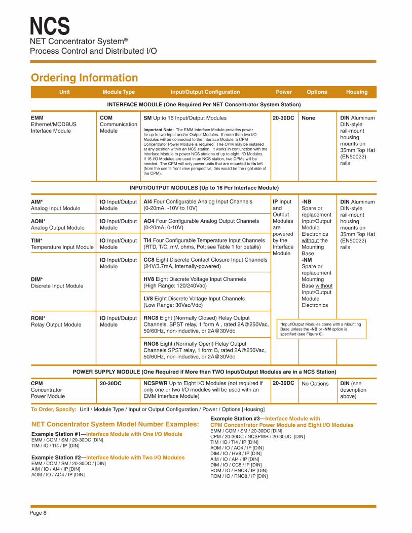
Ordering Information Unit Module Type Input/Output Configuration Power Options Housing
EMM Ethernet/MODBUS Interface Module
AIM* Analog Input Module
AOM* Analog Output Module
TIM* Temperature Input Module
DIM* Discrete Input Module
ROM* Relay Output Module
CPM Concentrator Power Module
COM Communication Module
IO Input/Output Module IO Input/Output Module IO Input/Output Module IO Input/Output Module
IO Input/Output Module
20-30DC
20-30DC
IP Input and Output Modules are powered by the Interface Module
20-30DC
DIN Aluminum DIN-style rail-mount housing mounts on 35mm Top Hat (EN50022) rails
DIN Aluminum DIN-style rail-mount housing mounts on 35mm Top Hat (EN50022) rails
DIN (see description above)
None
-NB Spare or replacement Input/Output Module Electronics without the Mounting Base -NM Spare or replacement Mounting Base without Input/Output Module Electronics
No Options
INTERFACE MODULE (One Required Per NET Concentrator System Station)
INPUT/OUTPUT MODULES (Up to 16 Per Interface Module)
POWER SUPPLY MODULE (One Required if More than TWO Input/Output Modules are in a NCS Station)
*Input/Output Modules come with a Mounting Base unless the -NB or -NM option is specified (see Figure 6).
Example Station #1—Interface Module with One I/O Module EMM / COM / SM / 20-30DC [DIN] TIM / IO / TI4 / IP [DIN] Example Station #2—Interface Module with Two I/O Modules EMM / COM / SM / 20-30DC / [DIN] AIM / IO / AI4 / IP [DIN] AOM / IO / AO4 / IP [DIN]
NET Concentrator System Model Number Examples:
To Order, Specify: Unit / Module Type / Input or Output Configuration / Power / Options [Housing]
Example Station #3—Interface Module with CPM Concentrator Power Module and Eight I/O Modules EMM / COM / SM / 20-30DC [DIN] CPM / 20-30DC / NCSPWR / 20-30DC [DIN] TIM / IO / TI4 / IP [DIN] AOM / IO / AO4 / IP [DIN] DIM / IO / HV8 / IP [DIN]AIM / IO / AI4 / IP [DIN]DIM / IO / CC8 / IP [DIN]ROM / IO / RNC8 / IP [DIN]ROM / IO / RNO8 / IP [DIN]
SM Up to 16 Input/Output Modules Important Note: The EMM Interface Module provides power for up to two Input and/or Output Modules. If more than two I/O Modules will be connected to the Interface Module, a CPM Concentrator Power Module is required. The CPM may be installed at any position within an NCS station. It works in conjunction with the Interface Module to power NCS stations of up to eight I/O Modules. If 16 I/O Modules are used in an NCS station, two CPMs will be needed. The CPM will only power units that are mounted to its left (from the user’s front view perspective, this would be the right side of the CPM).
AI4 Four Configurable Analog Input Channels (0-20mA, -10V to 10V) AO4 Four Configurable Analog Output Channels (0-20mA, 0-10V) TI4 Four Configurable Temperature Input Channels (RTD, T/C, mV, ohms, Pot; see Table 1 for details) CC8 Eight Discrete Contact Closure Input Channels (24V/3.7mA, internally-powered) HV8 Eight Discrete Voltage Input Channels (High Range: 120/240Vac)
LV8 Eight Discrete Voltage Input Channels (Low Range: 30Vac/Vdc) RNC8 Eight (Normally Closed) Relay Output Channels, SPST relay, 1 form A , rated 2A@250Vac, 50/60Hz, non-inductive, or 2A@30Vdc
RNO8 Eight (Normally Open) Relay Output Channels SPST relay, 1 form B, rated 2A@250Vac, 50/60Hz, non-inductive, or 2A@30Vdc
NCSPWR Up to Eight I/O Modules (not required if only one or two I/O modules will be used with an EMM Interface Module)
NET Concentrator System®
Process Control and Distributed I/O
NCS
Page 9
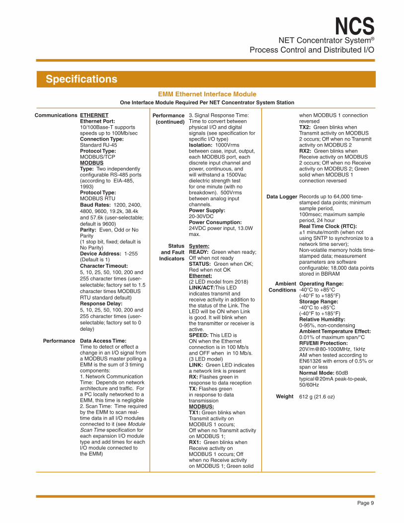
SpecificationsEMM Ethernet Interface Module
One Interface Module Required Per NET Concentrator System Station
Performance (continued)
Data Logger
Ambient Conditions
Weight
Communications ETHERNET Ethernet Port: 10/100Base-T supports speeds up to 100Mb/sec Connection Type: Standard RJ-45 Protocol Type: MODBUS/TCP MODBUS Type: Two independently configurable RS-485 ports (according to EIA-485, 1993) Protocol Type: MODBUS RTUBaud Rates: 1200, 2400, 4800, 9600, 19.2k, 38.4k and 57.6k (user-selectable; default is 9600) Parity: Even, Odd or No Parity (1 stop bit, fixed; default is No Parity) Device Address: 1-255 (Default is 1) Character Timeout: 5, 10, 25, 50, 100, 200 and 255 character times (user-selectable; factory set to 1.5 character times MODBUS RTU standard default) Response Delay: 5, 10, 25, 50, 100, 200 and 255 character times (user-selectable; factory set to 0 delay) Data Access Time: Time to detect or effect a change in an I/O signal from a MODBUS master polling a EMM is the sum of 3 timing components: 1. Network Communication Time: Depends on network architecture and traffic. For a PC locally networked to a EMM, this time is negligible2. Scan Time: Time required by the EMM to scan real-time data in all I/O modules connected to it (see Module Scan Time specification for each expansion I/O module type and add times for each I/O module connected to the EMM)
3. Signal Response Time: Time to convert between physical I/O and digital signals (see specification for specific I/O type) Isolation: 1000Vrms between case, input, output, each MODBUS port, each discrete input channel and power, continuous, and will withstand a 1500Vac dielectric strength test for one minute (with no breakdown). 500Vrms between analog input channels. Power Supply: 20-30VDCPower Consumption: 24VDC power input, 13.0W max. System: READY: Green when ready;Off when not ready STATUS: Green when OK;Red when not OKEthernet:(2 LED model from 2018)LINK/ACT:This LED indicates transmit and receive activity in addition to the status of the Link. The LED will be ON when Link is good. It will blink when the transmitter or receiver is active. SPEED: This LED is ON when the Ethernet connection is in 100 Mb/s and OFF when in 10 Mb/s.(3 LED model) LINK: Green LED indicates a network link is present RX: Flashes green in response to data reception TX: Flashes green in response to data transmissionMODBUS: TX1: Green blinks when Transmit activity on MODBUS 1 occurs; Off when no Transmit activity on MODBUS 1; RX1: Green blinks when Receive activity on MODBUS 1 occurs; Off when no Receive activity on MODBUS 1; Green solid
Status and Fault
Indicators
when MODBUS 1 connection reversedTX2: Green blinks when Transmit activity on MODBUS 2 occurs; Off when no Transmit activity on MODBUS 2RX2: Green blinks when Receive activity on MODBUS 2 occurs; Off when no Receive activity on MODBUS 2; Green solid when MODBUS 1 connection reversed
Records up to 64,000 time-stamped data points; minimum sample period, 100msec; maximum sample period, 24 hour Real Time Clock (RTC):±1 minute/month (when not using SNTP to synchronize to a network time server); Non-volatile memory holds time-stamped data; measurement parameters are software configurable; 18,000 data points stored in BBRAM Operating Range: -40°C to +85°C (-40°F to +185°F) Storage Range:-40°C to +85°C (-40°F to +185°F) Relative Humidity: 0-95%, non-condensingAmbient Temperature Effect: 0.01% of maximum span/°C RFI/EMI Protection: 20V/m@80-1000MHz, 1kHz AM when tested according to EN61326 with errors of 0.5% or span or lessNormal Mode: 60dB typical@20mA peak-to-peak, 50/60Hz
612 g (21.6 oz)
Performance

NET Concentrator System® Process Control and Distributed I/O
NCS
Page 10
Specifications (continued)AIM Analog Input Module (4 Channels)
Up to 16 Per Interface Module
Performance
Performance (continued)
Status and Fault
Indicators
Ambient Conditions
Weight
Input Ranges: Programmable for any range within: Current, 0-25mA (4mA minimum span) or Voltage, -10V to +10V (1V minimum span) Accuracy: ±0.01% of maximum spanInput Resolution: 20-bit Stability (% of max. span): Current: 1-year, 0.047%; 3-year, 0.081%; 5-year, 0.11%Voltage: 1-year, 0.066%; 3-year, 0.11%; 5-year, 0.15%Isolation: 500Vrms, continuous, from channel to channel, from each channel to case, and from each channel to terminals of other attached NCS modules; will withstand 1000Vrms dielectric strength test for one minute, with no breakdown, from each channel to case, and from each channel to terminals of other attached NCS modules Scan Time: The time required for the Interface Module to access process variable and status data from all four channels of the AIM is 16ms
Response Time: 60msInput Impedance: Current, 20ohms; Voltage, 1MohmMaximum Input Overrange: Current, ±100mA; Voltage, ±30VPower Supply: Power is supplied by the Interface Module, 4W maximum Input Filter: User-Programmable for 50Hz or 60Hz noise rejection Linearization Capability: Custom curve tables can be configured with up to 128 points using Internet Explorer web pages or PC-based software Transmitter Excitation: 21V/24mA excitation for powering a 2-wire transmitter Diagnostic Information: Status data available when polling channels includes A/D saturated; input signal out of linearized range; EEPROM failure; A/D converter failure; and run-time failure
One red/green LED per channel indicates proper channel operation (green) or that the channel is in a fault condition (red)
Operating Range: -40°C to +85°C (-40°F to +185°F) Storage Range:-40°C to +85°C (-40°F to +185°F) Ambient Temperature Effect: 0.01% of maximum span/°C Relative Humidity: 0-95%, non-condensing RFI/EMI Protection: 20V/m @20-1000MHz, 1kHz AM when tested according to ENC61000-4-3-1996. Common Mode Rejection: 100dB@50/60Hz Normal Mode Rejection: Current, 60dB typical@10mA peak-to-peak; Voltage, 60dB typical@1V peak-to-peak, 50/60Hz
As defined by SAMA PCM 31.1, field mounted category 562 g (19.8 oz)
Vibration
Advanced Control and MathUsing ISaGRAF Control Engine Software from ICS Triplex, the NET Concentrator System can be configured to deliver additional architecture, control, computation and functional capabilities including: • The ability to act as a single or multiple PID loop controller with
simple, cascade, split action and inverse capabilities.
• Sequential control language programmability based on IEC 61131-3, including ladder, function block diagram and structured text.
• Complex math capabilities including add, subtract, multiply and divide; absolute value; square root; integrate and totalize; exponential; natural logarithm; base10 logarithm; comparison; sine, cosine and tangent; arc sine, arc cosine and arc tangent.
• Highly functional peer-to-peer* configurations that allow “Free Channel Mapping” and “Sending a Process Signal to Multiple Locations.”
The ISaGRAF workbench software is available from Moore Industries for use in configuring custom applications. Alternatively, Moore Industries provides application development services for cost-effective integration of the ISaGRAF functions with the NCS. Consult the factory for details.
* Ethernet Peer-to-Peer Systems are accomplished using the EMM Interface Module combined with ICS Triplex ISaGRAF control software (available from Moore Industries). MODBUS Peer-to-Peer Systems are configured via the EMM Interface Module internal Internet Explorer Web browser or using the Moore Industries software package called NCS Config. MODBUS RTU Master (and Slave) serial port setups use the EMM configuration tools. MODBUS RTU Master additionally uses the ‘schedule.ini’ file.

NET Concentrator System®
Process Control and Distributed I/O
NCS
Page 11
Versatile Data Link OptionsIn addition to Ethernet or twisted wire pair (for MODBUS RTU), our versatile communication link options overcome long-distance, normally impassable, and hazardous environments (see Page 16 for additional information).
Wireless (Radio)—Where wires can’t be run for practical or economic reasons, spread spectrum wireless radio (RF) communication provides accurate and reliable connectivity between sites. Distances between modems can be up to 20 miles, and repeaters can extend coverage even further. Telephone Modem—Inexpensively transmit process data unlimited distances over leased or dial-up telephone lines. We offer modems and RS-485 to RS-232C/RS-422 (for modem) converters.
Fiber Optic Cable—For hazardous or exceptionally noisy environments, light is an effective strategy. We offer fiber optic converters and other accessories needed for implementing fiber optic networks.
Redundant Communication Links—For applications whereyou can’t afford to lose data, the NET Concentrator SystemEMM Interface Module provides redundant RS-485 communication links as standard for connecting a backup digital communications link. The redundant link can be implemented in both peer-to-host systems and peer-to-peer systems. The secondary communications link is independent of the primary link. If the primary link is severed or otherwise compromised, data transmission will continue within the NET Concentrator System network.
AOM Analog Output Module (4 Channels) Up to 16 per Interface Module
Specifications (continued)
Performance (continued)
Performance (continued)
Status and Fault
Indicators
Ambient Conditions
Weight
Performance Output Ranges: Programmable for any range within: Current (sink or source), 0-23.6mA or Voltage, 0-11VAccuracy: ±0.015% of maximum span Output Resolution: 18-bit Stability (% of max. span): Current: 1-year, 0.012%; 3-year, 0.020%; 5-year, 0.026%Voltage: 1-year, 0.066%; 3-year, 0.11%; 5-year, 0.15% Isolation: 500Vrms, continuous, from channel to channel, from each channel to case, and from each channel to terminals of other attached NCS modules; will withstand 1000Vrms dielectric strength test for one minute, with no breakdown, from each channel to case, and from each channel to terminals of other attached NCS modules Scan Time: The time required for the Interface Module to access process variable and status data from all four channels of the AOM is 16msResponse Time: 50ms to 90% of final value on a step input
Output Damping: Increases response time by adjusting filter time constant from 0-30 secondsRipple: Current, 10mV peak-to-peak measured across a 250ohm load resistor; Voltage, 50mV peak-to-peak maximum Load Capability: Current, 0-1000ohms (source), 42V maximum (sink) 1500ohms; Voltage, 0-5mA (2000ohms minimum load)Output Limiting: Current output is guaranteed up to 21.6mA (or 10% of full scale above the programmed full value) and limits at 23.6mA; Voltage output accuracy is guaranteed up to 10.5V (or 5% of full scale above the programmed full value) and limits at 11.0V Load Effect (current outputs): 0.01% of span from 0 to maximum load resistance on current outputOutput Failure Mode: Outputs are programmable to either hold last value or go to a pre-defined value on error upon lost communication with the Interface Module or upon receiving invalid primary variable data
Power Supply: Power is supplied by the Interface Module, 4W maximum Diagnostic Information: Status data available when polling channels includes ROM failure; RAM failure; EEPROM; open current output; EEPROM checksum error One red/green LED per channel indicates proper channel operation (green) or that the channel is in a fault condition (red)
Operating Range: -40°C to +85°C (-40°F to +185°F) Storage Range:-40°C to +85°C (-40°F to +185°F) Ambient Temperature Effect: 0.01% of maximum span/°C Relative Humidity: 0-95%, non-condensing RFI/EMI Protection: 20V/m@20-1000MHz, 1kHz AM when tested according to ENC61000-4-3-1996
As defined by SAMA PCM 31.1, field mounted category 765 g (27 oz)
Vibration

NET Concentrator System® Process Control and Distributed I/O
NCS
Page 12
Operating Range: -40°C to +85°C (-40°F to +185°F) Storage Range:-40°C to +85°C (-40°F to +185°F) Ambient Temperature Effect: See Table 1 Effect on Reference Junction Compensation: ±0.005°C/°C Relative Humidity: 0-95%, non-condensing RFI/EMI Immunity: 20V/m @20-1000MHz, 1kHz AM when tested according to ENC6100-4-3-1996; Effect on RTD/ohms Input: 0.4°C/0.1ohms, maximum; Effect on Thermocouple/Millivolt Input: 1.0°C/40µV, maximum Common Mode Rejection: 100dB@50/60Hz Normal Mode Rejection: 50dB [email protected] peak-to-peak, 50/60Hz
As defined by SAMA PCM 31.1, field mounted category 589 g (20.7 oz)
Specifications (continued)TIM Temperature Input Module (4 Channels)
Up to 16 Per Interface Module
Temperature Measurement Advantages We’ve drawn on years of temperature measurement experience to produce the most stable, accurate and functional measurements available from an I/O system. “Total Sensor Diagnostics”—This patented Moore Industries feature can save you from costly lost production time and hours of troubleshooting. If the sensor breaks or otherwise stops sending a signal during operation, data is made available in the OPC server via the MODBUS registers. The NCS also provides a plain-English error message that can be read from the system’s PC web pages. If the sensor being utilized is an RTD, the web pages will display the type and location of the error. Trims to Read Specific Sensor Curve Segments—Most temperature measurement devices can be calibrated to measure a specific range within
a sensor’s overall curve capability. However, for even greater measurement accuracy, our interface’s trim capabilities go much further. The NET Concentrator System’s temperature input channels can be trimmed with two data points within the selected zero and span measurement range. This advantage allows a complete process range to be monitored, while placing measurement emphasis on a specific segment of the range most critical to the process. Precise Linearization and RJC—The NCS uses an advanced linearization method to minimize the conformance error. Its Reference (Cold) Junction Compensation techniques produce stable readings even in fluctuating ambient temperature conditions. For non-linear inputs, create custom linearization curves using our web-based software.
Performance
Weight
Performance (continued)
Status and Fault
Indicators
Ambient Conditions
Input Ranges: See Table 1Accuracy: See Table 1 Reference Junction Compensation Accuracy: ±0.45°C Input Resolution: 20-bit Stability (% of max. span): RTD: 1-year, 0.013%; 3-year, 0.023%; 5-year, 0.029%Thermocouple: 1-year, 0.0084%; 3-year, 0.015%; 5-year, 0.019% Isolation: 500Vrms, continuous, from channel to channel, from each channel to case, and from each channel to terminals of other attached NCS modules; will withstand 1000Vrms dielectric strength test for one minute, with no breakdown, from each channel to case, and from each channel to terminals of other attached NCS modules Scan Time: The time required for the Interface Module to access process variable and status data from all four channels of the TIM is 16msResponse Time: 150ms
Input Impedance (T/C): 40Mohms, nominalMaximum Input Overrange: ±5Vdc peak, maximumExcitation Current (RTD and Ohms): 250 microamps nominal Power Supply: Power is supplied by the Interface Module, 1.5W maximum Linearization Capability: Custom curve tables can be configured with up to 128 points using Internet Explorer web pages or PC-based software Input Filter: Programmable for 50 or 60Hz noise rejection Diagnostic Information: Status data available when polling channels includes A/D saturated; input signal out of linearized range; broken RJC; broken sensor wire (#1, #2, #3, or #4); run-time failure; EEPROM failure; A/D converter fail
One red/green LED per channel indicates proper channel operation (green) or that the channel is in a fault condition (red)
Vibration
NET Concentrator System®
Process Control and Distributed I/O
NCS
Page 13
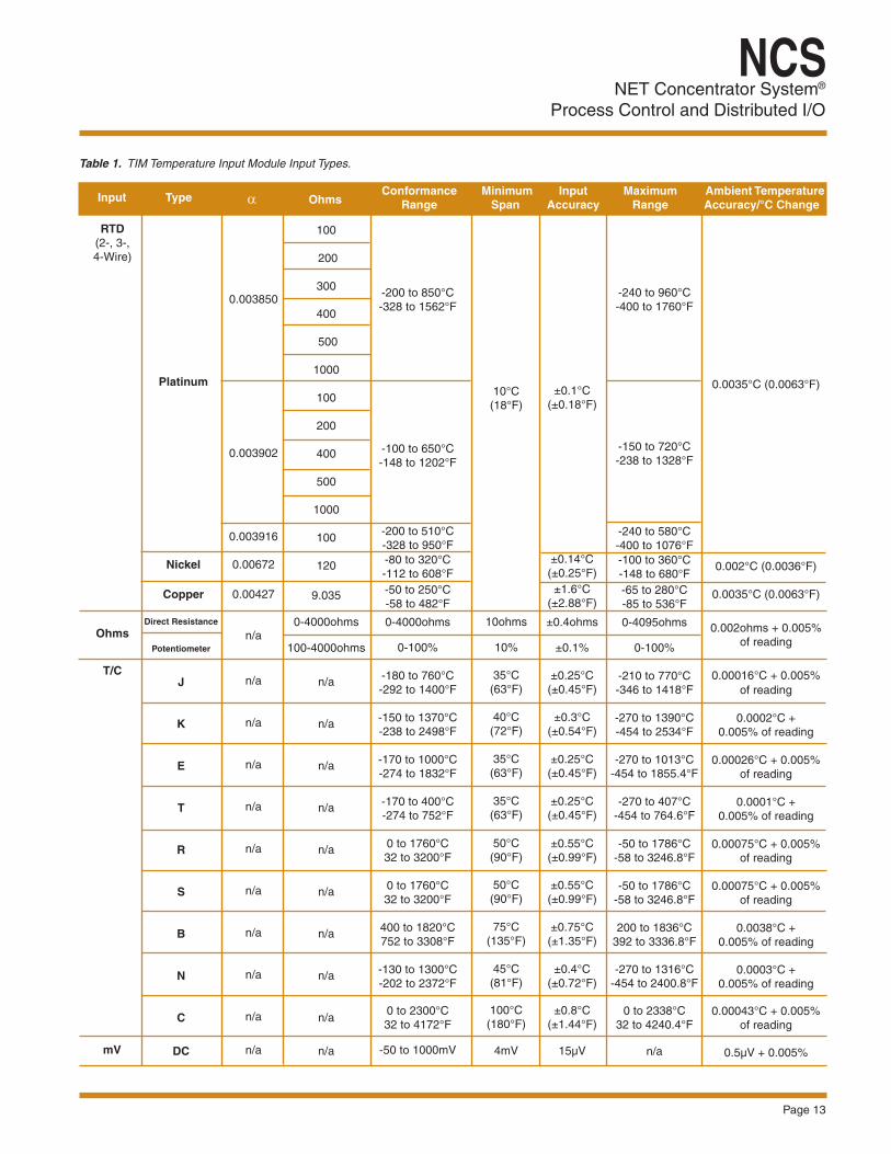
Table 1. TIM Temperature Input Module Input Types.
0.0035°C (0.0063°F)
0.002°C (0.0036°F)
0.0035°C (0.0063°F)
0.002ohms + 0.005% of reading
0.00016°C + 0.005% of reading
0.0002°C +
0.005% of reading
0.00026°C + 0.005% of reading
0.0001°C +
0.005% of reading
0.00075°C + 0.005% of reading
0.00075°C + 0.005%
of reading
0.0038°C + 0.005% of reading
0.0003°C +
0.005% of reading
0.00043°C + 0.005% of reading
0.5µV + 0.005%
±0.1°C (±0.18°F)
±0.14°C (±0.25°F)
±1.6°C (±2.88°F) ±0.4ohms
±0.1%
±0.25°C
(±0.45°F)
±0.3°C (±0.54°F)
±0.25°C
(±0.45°F)
±0.25°C (±0.45°F)
±0.55°C
(±0.99°F)
±0.55°C (±0.99°F)
±0.75°C
(±1.35°F)
±0.4°C (±0.72°F)
±0.8°C
(±1.44°F)
15µV
0.003850
0.003902
0.003916
0.00672
0.00427
n/a
n/a
n/a
n/a
n/a
n/a
n/a
n/a
n/a
n/a
n/a
100
200
300
400
500
1000
100
200
400
500
1000
100
120
9.035
0-4000ohms
100-4000ohms
n/a
n/a
n/a
n/a
n/a
n/a
n/a
n/a
n/a
n/a
-200 to 850°C -328 to 1562°F
-100 to 650°C -148 to 1202°F
-200 to 510°C -328 to 950°F -80 to 320°C -112 to 608°F -50 to 250°C -58 to 482°F 0-4000ohms
0-100%
-180 to 760°C -292 to 1400°F
-150 to 1370°C -238 to 2498°F
-170 to 1000°C -274 to 1832°F
-170 to 400°C -274 to 752°F
0 to 1760°C 32 to 3200°F
0 to 1760°C 32 to 3200°F
400 to 1820°C 752 to 3308°F
-130 to 1300°C -202 to 2372°F
0 to 2300°C 32 to 4172°F
-50 to 1000mV
-240 to 960°C -400 to 1760°F
-150 to 720°C -238 to 1328°F
-240 to 580°C -400 to 1076°F -100 to 360°C -148 to 680°F -65 to 280°C -85 to 536°F 0-4095ohms
0-100%
-210 to 770°C -346 to 1418°F
-270 to 1390°C -454 to 2534°F
-270 to 1013°C
-454 to 1855.4°F
-270 to 407°C -454 to 764.6°F
-50 to 1786°C
-58 to 3246.8°F
-50 to 1786°C -58 to 3246.8°F
200 to 1836°C
392 to 3336.8°F
-270 to 1316°C -454 to 2400.8°F
0 to 2338°C
32 to 4240.4°F
n/a
Direct Resistance
Potentiometer J
K E T R S B N C
DC
Input Type Input Accuracy
Maximum Range
Ohms
Platinum
Nickel
Copper
T/C
RTD (2-, 3-, 4-Wire)
mV
Ambient Temperature Accuracy/°C Changeα Conformance
Range Minimum
SpanOhms
10°C (18°F)
10ohms
10%
35°C (63°F)
40°C
(72°F)
35°C (63°F)
35°C
(63°F)
50°C (90°F)
50°C
(90°F)
75°C (135°F)
45°C
(81°F)
100°C (180°F)
4mV
NET Concentrator System® Process Control and Distributed I/O
NCS
Page 14
DIM Discrete Voltage Input Module (8 Channels) Up to 16 Per Interface Module
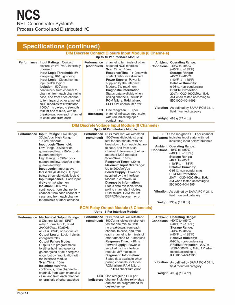
Specifications (continued)DIM Discrete Contact Closure Input Module (8 Channels)
Up to 16 Per Interface Module
Input Ratings: Contact closure, 24V/3.7mA, internally poweredInput Logic Threshold: 8V low-going; 16V high-going Input Logic: Closed contact input yields logic 1 Isolation: 500Vrms, continuous, from channel to channel, from each channel to case, and from each channel to terminals of other attached NCS modules; will withstand 1000Vrms dielectric strength test for one minute, with no breakdown, from each channel to case, and from each
Performance channel to terminals of other attached NCS modules Scan Time: 16ms Response Time: <12ms with contact debounce disabledPower Supply: Power is supplied by the Interface Module, 3W maximum Diagnostic Information: Status data available when polling channels, includes: ROM failure; RAM failure; EEPROM checksum error
One red/green LED per channel indicates input state, with red indicating open contact input
Ambient Conditions
Performance (continued)
Weight
ROM Relay Output Module (8 Channels) Up to 16 Per Interface Module
Mechanical Output Ratings: 8-Channel Model: SPST relay, 1 form A or B, rated 2A@250Vac, 50/60Hz, or 2A@30Vdc, non-inductive Output Logic: Logic 1 yields energized relay Output Failure Mode: Outputs are programmable to either hold last value, or go energized or de-energized upon lost communication with the interface moduleScan Time: 16msIsolation: 500Vrms, continuous, from channel to channel, from each channel to case, and from each channel to terminals of other attached
Performance
LED Indicators
NCS modules; will withstand 1000Vrms dielectric strength test for one minute, with no breakdown, from each channel to case, and from each channel to terminals of other attached NCS modulesResponse Time: <10msPower Supply: Power is supplied by the interface module, 3W maximum Diagnostic Information: Status data available when polling channels, includes: ROM failure; RAM failure; EEPROM checksum error
One red/green LED per channel indicates relay state and can be programmed for desired sense
Performance (continued)
Ambient Conditions
Operating Range: -40°C to +85°C (-40°F to +185°F) Storage Range:-40°C to +85°C (-40°F to +185°F) Relative Humidity: 0-95%, non-condensing RFI/EMI Protection: 20V/m @20-1000MHz, 1kHz AM when tested according to IEC1000-4-3-1995
As defined by SAMA PCM 31.1, field mounted category 493 g (17.4 oz)
Performance LED Indicators
Performance (continued)
Ambient Conditions
Weight
Input Ratings: Low Range, 30Vac/Vdc; High Range: 120/240Vac/VdcInput Logic Threshold: Low Range: <9Vac or dc guaranteed low, >15Vac or dc guaranteed high; High Range: <55Vac or dc guaranteed low, >90Vac or dc guaranteed high Input Logic: Input above threshold yields logic 1; Input below threshold yields logic 0 Input Impedance: Each input draws <4mA when on Isolation: 500Vrms, continuous, from channel to channel, from each channel to case, and from each channel to terminals of other attached
NCS modules; will withstand 1000Vrms dielectric strength test for one minute, with no breakdown, from each channel to case, and from each channel to terminals of other attached NCS modules Scan Time: 16ms Response Time: <30msMaximum Input Overrange: Up to 260Vac/VdcPower Supply: Power is supplied by the Interface Module, 1W maximum Diagnostic Information: Status data available when polling channels, includes: ROM failure; RAM failure; EEPROM checksum error
One red/green LED per channel indicates input state, with red indicating input below threshold
Operating Range: -40°C to +85°C (-40°F to +185°F) Storage Range:-40°C to +85°C (-40°F to +185°F) Relative Humidity: 0-95%, non-condensing RFI/EMI Protection: 20V/m @20-1000MHz, 1kHz AM when tested according to IEC1000-4-3-1995
As defined by SAMA PCM 31.1, field mounted category
536 g (18.8 oz)
Operating Range: -40°C to +85°C (-40°F to +185°F) Storage Range:-40°C to +85°C (-40°F to +185°F) Relative Humidity: 0-95%, non-condensing RFI/EMI Protection: 20V/m @20-1000MHz, 1kHz AM when tested according to IEC1000-4-3-1995
As defined by SAMA PCM 31.1, field mounted category
493 g (17.4 oz)
Weight
LED Indicators
Vibration
Vibration
Vibration

NET Concentrator System®
Process Control and Distributed I/O
NCS
Page 15
Inputs (Power): 20-30VdcOutput (Power): Each CPM provides power to up to eight NCS I/O modules Isolation: 500Vrms, continuous, and will withstand 1000Vrms dielectric strength test for 1 minute with no breakdown, between power input, each MODBUS port, case and terminals of other attached NCS modules Startup Time: 10ms Power Consumption: 40W maximum
Power LED: A green LED turns on to indicate that power is being supplied to the power terminals. Status LED: A green LED turns on to indicate that power is available at the CPM module’s output
Operating Range: -40°C to +85°C (-40°F to +185°F) Storage Range:-40°C to +85°C (-40°F to +185°F)
Relative Humidity: 0-95%, non-condensing RFI/EMI Protection: 20V/m@20-1000MHz, 1kHz AM when tested according to ENC61000-4-3-1996
As defined by SAMA PCM 31.1, field mounted category 585 g (20.7 oz)
CPM Power Supply Module One Or More Required Per NET Concentrator System Station if There Are More Than Two Input/Output Modules
Ambient Conditions (continued)
Weight
Performance
Figure 9. Installation Dimensions.
Specifications (continued)
Power and Status
Indicators
Ambient Conditions
Vibration
149mm(5.9 in)
117mm(4.6 in)
229mm(9.0 in)
69mm(2.7 in)
75mm(2.9 in)
Input Module Output Module
FRONT VIEW
135mm(5.3 in)
Input Modules
135mm(5.3 in)
SIDE VIEW
SIDE VIEW
Output Modules
75mm(2.9 in)
EMM Interface Module
CHANNEL 1
CHANNEL 2
CHANNEL 3
CHANNEL 4
CHANNEL 1
CHANNEL 2
CHANNEL 3
CHANNEL 4
ModuleNumber
POWER RS-485 ETHERNET
ETHERNET/MODBUS MODULEEMM
ModuleNumber
SIDE VIEW
91mm(3.6 in)
135mm(5.3 in)
87mm(3.4 in)
Lorem ipsum
READY
STATUS RX2 TX2
TX1RX1 LINK/ACT
SPEEDETHERLINKRS-485

NET Concentrator System® Process Control and Distributed I/O
NCS
Industrial Ethernet Switches Intelligent multi-port communications switches automatically determine and remember where a NET Concentrator System Station is located, and routes messages only through the appropriate port to that Station. This minimizes network loading and improves deterministic communications over Ethernet. Ethernet Routers Connects multiple NET Concentrator System segments or sub-networks, forwards messages from one network to another, and provides message traffic isolation between segments.
RS-485 to RS-232C/RS-422 Converter For MODBUS (RS-485) networks, converts the RS-485 signal to either RS-232C or RS-422 standard to allow direct interface with a modem or computer-based systems, such as a PC.
RS-485 to Fiber Optics Converter Converts the NCS’s RS-485 signal to light for signal transmission over a fiber optic cable.
Ethernet/RS-485 Repeater Extends the NCS’s (MODBUS models) transmission distance an additional 10,000 feet over its limit.
System AccessoriesWireless RF Modems Where wires can’t be run for practical or economic reasons, spread spectrum wireless radio (RF) communication provides accurate and reliable connectivity between sites. Distances between modems can be up to 20 miles, and repeaters can extend coverage even further.
Short Haul Modem For MODBUS (RS-485) networks, the Short Haul Modem extends the NCS’s allowable transmission distance to 10 miles (16km).
Dial-Up Modem The Dial-Up (or Dedicated Modem) permits unlimited transmission distances over a regular switched telephone line or leased dedicated line.
Data Line (Surge) Protectors Mounts next to the NCS to protect the data link from damaging voltage and current surges caused by lightning, welding, heavy electrical equipment and switch gears.
Instrument Power Supplies Moore Industries offers a complete line of instrument power supplies for mounting alongside and powering the NET Concentrator System.
Redundant Power Supply DIN-style, rail-mount module accepts two power supply inputs and provides an uninterrupted power source by passing the highest voltage.
Certifications
Factory Mutual – FM Approvals – cFMus (US/Canada), Non-Incendive – Class I, Division 2, Groups A, B, C, DT4A@40°C, T4@60°C, T3C@85°C Max. Op. Ambient For use in General Locations and/or Hazardous ‘Classified’ Locations when mounted in protective and suitable enclosures
CE Conformant – EMC Directive 2014/30/EU EN61326; Low Voltage Directive 2014/35/EU EN61010
United States • [email protected]: (818) 894-7111 • FAX: (818) 891-2816
Australia • [email protected]: (02) 8536-7200 • FAX: (02) 9525-7296
Belgium • [email protected]: 03/448.10.18 • FAX: 03/440.17.97The Netherlands • [email protected]
Tel: (0)344-617971 • FAX: (0)344-615920
China • [email protected]: 86-21-62491499 • FAX: 86-21-62490635
United Kingdom • [email protected]: 01293 514488 • FAX: 01293 536852
Specifications and information subject to change without notice. Page 16


![PIH Installation Manual - Moore Industries · 2019-01-29 · PIH User Manual Field Mount Pressure-to-Current Transmitter 123-723 00C January 2018 [2] Moore Industries-International,](https://img.pdfslide.us/doc/110x75/5f372a487a73c57bf450f464/pih-installation-manual-moore-industries-2019-01-29-pih-user-manual-field-mount.jpg)