Embed Size (px)
Citation preview
Montara H1 ST1 End of Well Report
( Approval Schlumberger QC
Name Signature Date
Contents
1. General Information
2. Geomagnetic Data and Survey Reference Criteria
3. Definitive Survey
4. Well Plot
5. Drilling & MWDILWD Run Summary
6. BHA Reports
7. Drilling Parameter Sheets
8. Drilling Tool Run Reports
9. Dull Bit Grading
10. Service Quality Issues
11. Depth Control Summary
Schlumberger
Schlumberger
1. General Information
Schlumberger
Well Name:
Rig:
Field:
Location:
Country:
Cell Members:
General Information
Montara H1 ST1
West Atlas
Montara
AClL7
Australia
David Gibson Charlie Maramara Rika Kartorahardjo
LWD Engineer LW0 Engineer LWD Engineer
Jody Leahey Mat t Blacker
Town Contacts: Dave Rapp H. Spoljaric Dave Wallace
Company Representatives: Noel Treasure Lindsey Wishardt Paul O'Shea Craig Klumpp
Dave Hartney Mike Woodmansee
Directional Driller Directional Driller
Location Manager Drilling Services Manager R&M Supervisor Perth
Company Man Company Man Company M a n Company Man
Wellsite Geologist Wellsite Geologist
2. Geomagnetic Data and Survey Reference Criteria
--
Schlum ber ger
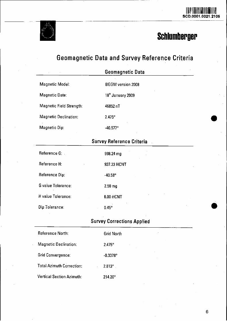
Geomagnetic Data and Survey Reference Criteria
Geomagnetic Data
Magnetic Model: BGGM version 2008
Magnetic Date: 18" January 2009
Magnetic Field Strength: 46852 nT
Magnetic Declination: 2.475" 0 Magnetic Dip: -40.577"
Survey Reference Criteria
Reference G: 998.24 mg
Reference H: 937.23 HCNT
Reference Dip: -40.58"
G value Tolerance: 2.50 mg
H value Tolerance:
Dip Tolerance:
6.00 HCNT
0.45"
Survey Corrections Applied
Reference North: Grid North
Magnetic Declination: 2.475"
Grid Convergence: -0.3378"
Total Azimuth Correction: 2.81 3"
Vertical Section Azimuth: 214.20"
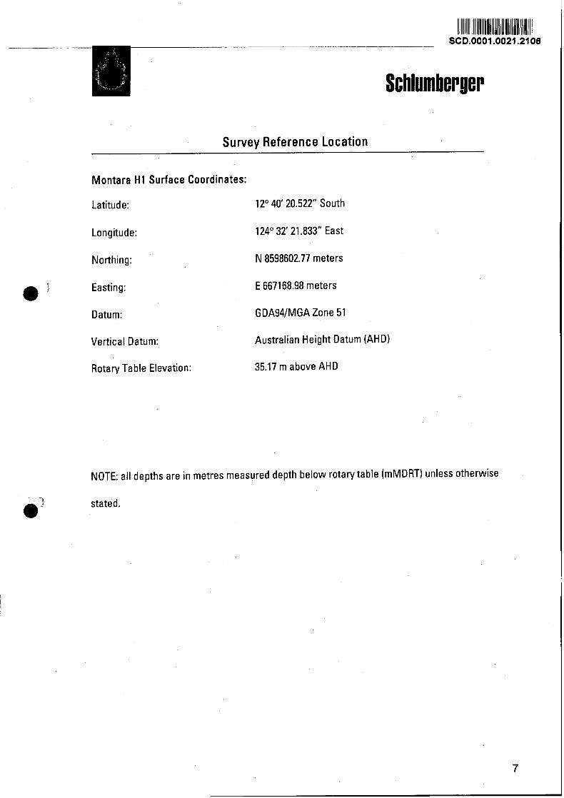
Survey Reference Location
Montara H1 Surface Coordinates:
Latitude: 12" 40' 20.522" South
Longitude:
Northing:
Easting:
124' 32' 21.833" East
N 8598602.77 meters
E 667168.98 meters
Datum: GDA94lMGA Zone 51
Vertical Datum: Australian Height Datum (AHD)
Rotary Table Elevation: 35.17 m above AHD
NOTE: all depths are in metres measured depth below rotary table (mMDRT) unless otherwise
stated.
Schlumber ger
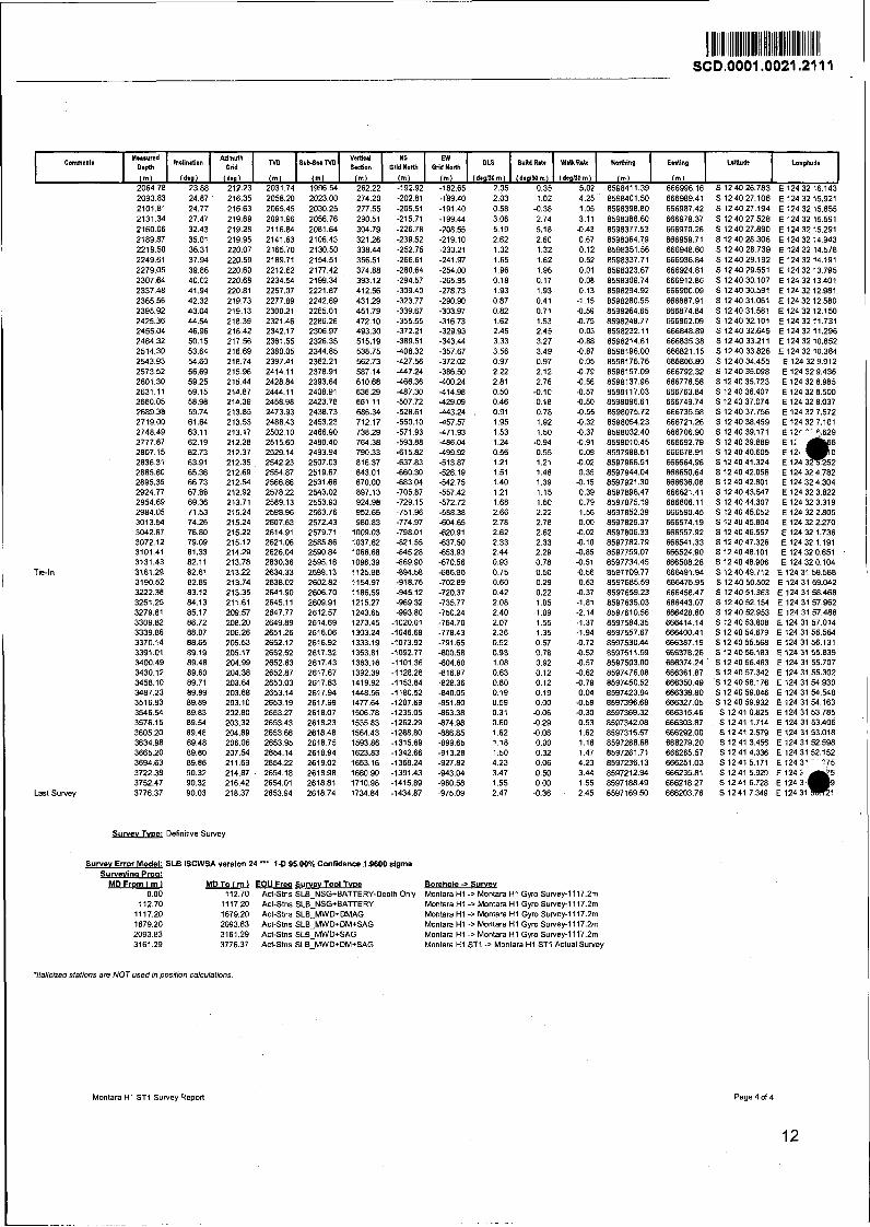
3. Definitive Survey
Montara H1 ST1 Survev Report
112.00 0.45
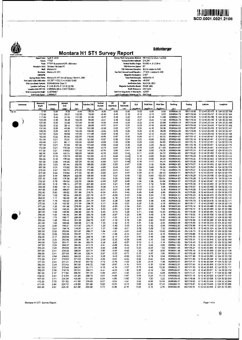
Montara H1 S T 1 Survey Report
R.@ Dab: April 18.2W9 Client PTTEF Field: PTTW AustralasidACRL-YMonlara
htnuturs Islot: Monlara l Monlara H1 Well: Monlara H I
B o n b b : Montara H1 S11 UWAPI:
s v m y Name l D I : Montara H I STl Actual Survey I March 4.2009 TorllAHDIDDIIEI(Dr.ri.: 150.W7~11752.11m/6.089100660
Grld Coordlnrta Spbm: GOA94lMGA94 Zone 51 Losltlon bVLong: S 12 40 20.470, E 124 32 22158
k s t l o n G M WE YIX: N 859W4.3W m, E 667178.BOO m Odd Cormrpnse An+: 0.33780481'
Orid Suh Factor 0,99994577
Page l of 4
- Sunny I DLS CompuhLn Mdhod: Minimum Curvature I Lubinski
VsBcrl Section MmuLh: 214.2Ml. VarUcaI S*ctkn Orlgln: N O.WO m, E O.OW m ND Rd*nncs Datum: RT
TVD Rderanse Elsvrtlon: 35.2 m relal'we to AHO Sal Bed IGmund bnl Ehvdon: -77.W m relative l0 AHD
MwnsUc DwlruUon: 2.467' Tots1 Field Sbmgh: 46854.910 nT
M r p d k Dip: 40.569' DcdlnNen Dab: March M. 2009
Magnls Dulination Modal: BGGM 2008 N& Refmnea: Grid North
Total Con Hag Notth* Grld Now +2.805' k r l Coodlnlln Rduenced To: Well Head
Inclination 2 2.72
2.75 2.82 2.86 2.97 3.04 3.01 3.07 3.19 3.27 3.36 3.37 3.41 3.42 3.43 3.52 3.57 3.61 3.66 3.76 3.90 4.04 4.16 4.22 4.32 4.39 4.43 4.48 4.51 4.56 4.61 4.66 4.67 4.71 4.76 4.79 4.76 4.80 4.84 4.94 4.95 5.00 5.10 5.19 5.19 5.22 5.23 5.28 5.38 5.34 5.27 5.32 5.39 5.39 5.41 5.47 5.52 5.65 5.47 5.47 5.37 5.34 5.34 5.29 5.28 5.32 5.25 5.20 5.25 5.27 5.07 5.21 5.21 5.13 5.08 5.06 5.04 5.08 5.14 5.16 5.18 5.22 5.26 5.26 5.36 5.37
Grid N w t h Grid Notth 3-J -5.53 -2.46 -5.69 -2.64 -5.86 -2.81 6.03 -2.99 6.20 -3.18 6.38 -3.37 6.55 -3.57 4.73 -3.77 6.90 -3.98 -7.08 -4.20 -7.26 -4.42 -7.44 -4.66 -7.62 -4.89 -7.80 -5.13 -7.98 -5.37 -8.17 -5.61 -8.36 -5.85 -8.55 -6.10 -8.74 -6.35 -8.94 -6.60 -9.15 -6.86 -9.37 -7.13 -9.60 -7.40 -9.84 -7.68
-10.08 -7.97 -10.32 -8.26 -10.57 -8.55 -10.82 -8.85 -11.07 -9.15 -11.32 -9.46 -1 1.58 -9.76 -1 1.83 -10.07 -12.09 -10.39 -12.35 -10.71 -12.61 -11.03 -12.87 -11.36 -13.13 -11.68 -13.38 -12.01 -13.65 -12.34 -13.91 -12.67 -14.19 -13.00 -14.46 -13.34 -14.74 -13.67 -15.03 -14.02 -15.33 -14.36 -15.62 -14.70 -15.92 -15.05 -16.22 -15.40 -16.52 -15.75 -16.82 -16.11 -17.12 -16.46 -17.42 -16.81 -17.73 -17.16 -18.03 -17.52 -18.34 -17.88 -18.65 -18.24 -18.96 -18.60 -19.28 -18.97 -19.59 -19.34 -19.90 -19.70 -20.20 -20.06 -20.50 -20.42 -20.80 -20.78 -21.10 -21.13 -21.39 -21.49 -21.68 -21.85 -21.97 -22.20 -22.26 -22.55 -22.56 -22.90 -22.85 -23.25 -23.14 -23.60 -23.42 -23.95 -23.71 -24.30 -24.00 -24.64 -24.28 -24.98 -24.57 -25.33 -24.85 -25.66 -25.13 -26.00 -25.41 -26.35 -25.70 -26.69 -25.99 -27.04 -26.28 -27.38 -26.58 -27.73 -26.88 -28.07 -27.18 -28.43 -27.49 -28.78
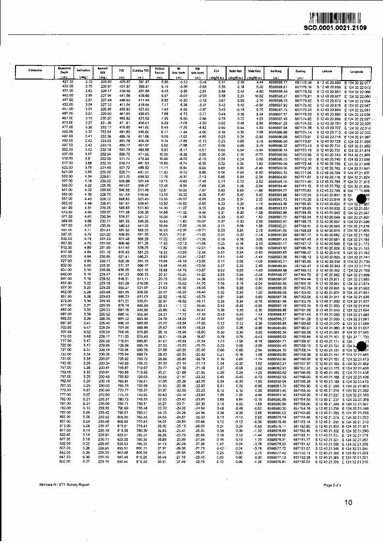
Montara H1 ST1 Survey Report Page 2 of 4
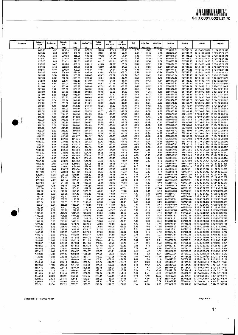
Montara H1 ST1 Survey Report Page 3 of 4
CCmrmenlr ND Sub-SmND GOriklh Gd&dh
I m l ( m ) ( m ) ( m ) ( m ) 857.00 5.37 229.34 855.42 820.22 39.36 -27.79 -29.13 0.11 0.00 1.20 8598576.51 667149.67 S 12 40 21.380 E 124 32 21.198
tlorthlng
(m1
DLS
( d e p o m )
Ewling
I m l
Build FMe
( d a m m )
WnLR*
( d e g l ~ m )
L.(iib Longitude
2093.83 2101.81 2131.34 2160.06 2189.87 221 9.50 2249.61 2279.05 2307.64 2337.48 2365.56 2395.92 2425.36 2455.04 2484.32 2514.30 2543.93 2573.52 2601.30 2631.11 2660.05 2689.38 2719.00 2748.49 2777.87 2807.15 2836.31 2865.80 2895.35 2924.77 2954.69 2984.05 3013.54 3042.67 3072.12 3101.41 3131.43
Tie-In 3161.29 3190.52 3222.38 3251.25 3279.81 3309.82 3339.86 3370.14 3391.01 3400.49 3430.12 3458.10 3487.23 3516.83 3546.54 3576.15 3605.20 3634.98 3665.20 3694.63 3722.38 3752.47
Last Survey 3776.37
Survev T v ~ e : Definitive Survey
Commmls
Survev Ermr Model: SLB ISCWSA version 24 ** 1-D 95.00% Confidence 1.9600 slgma
2064.78 23.88 212.23 2031 74 1996.54 262.22 -192.92 -182.65 2.05 0.35 5.02 859841 1.39 666996.16 S 12 40 26.783 E 124 32 16.143 ( m )
Survevins Proa: MD From l m l MD To ( m l EOU Freq Survev Tool T v ~ e Borehole * Survey
0.00 112.70 Act-Stns SLB-NSG+BATTERY-Depth Only Montara H1 -> Montara H1 Gyro Survey-l117.2m
Inclination
I d ~ l
112.70 1 1 17.20 ~ c t - ~ t n s SLB:NSG+BATTERY Montara H1 -> Monlara H1 Gyro Survey-1117.2m 1117.20 1679.20 Act-Stns SLB-MWD+DMAG Montara H1 -> Montara H1 Gyro Survey-1117.2m 1679.20 2093.83 Act-Stns SLB-MWD+DM+SAG Montara H1 -> Montara H1 Gyro Suney-1117.2m 2093.83 3161.29 Act-Stns SLB-MWDcSAG Montaa H1 -> Montara H1 Gyro Survey-1117.2m 3161 29 3776.37 Act-Stns SLB-MWD+DM+SAG Montaa H1 SS1 -> Montara H1 ST1 Actual Survey
(den)
'Malicized stations are NOT used in position calculations
ND
( m 1
Montara H1 S71 Survey Report
SuMuTVD
( m 1
Page 4 of 4
12
( m ) ( m ) ( m )
Build Rat*
IdtglMrn)
OLS
(d.glMm)
WdkRaLr
IdeglJDm)
Nofing
( m )
Earting
( m )
W i d e Lon&ds
Schlumber ger
4. Well Plot
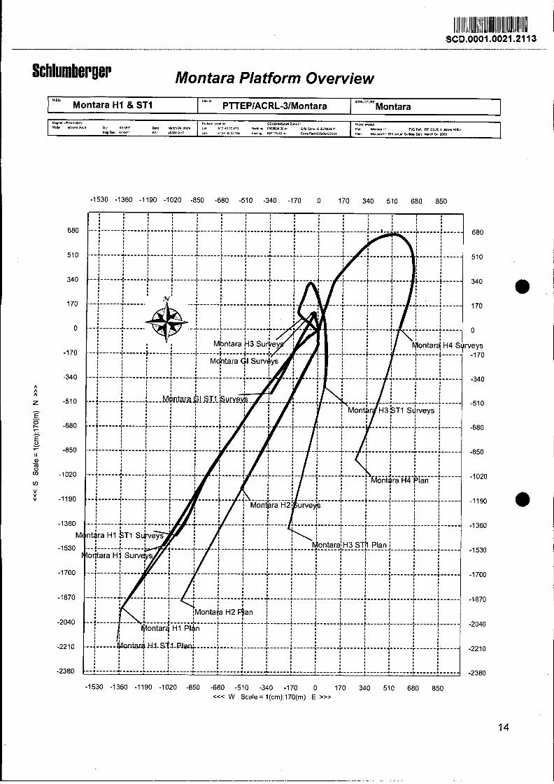
Montara Platform Overview
0
veys -1 70
-1530 -1360 -1190 -1020 -850 -680 -510 -340 -170 0 170 340 510 680 850 c<< W Scale =' l(cm):170(rn) E >>>
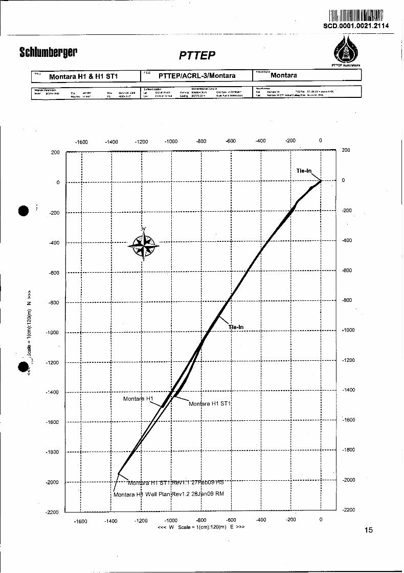
PTTEP P T E P AultnIaSIa
S R W T V R E
Montara H1 8 H1 ST1 I "" PTTEPIACRL-3IMontara Montara 1
-1600 -1400 -1200 -1000 -800 -600 -400 -200 0
<<< W Scale = l(cm):120(rn) E >>>
PTTEP
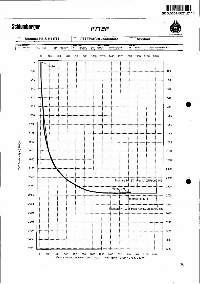
0 180 360 540 720 900 1080 1260 1440 1620 1800 1980 2160 2340 Vertical Section (m) Azim = 214.24 Scale = l(cm) :180(m) Origin = 0 NI-S, 0 El-W
5. Drilling & MWDILWD Run Summary
Sc hlum ber !er PTTEP Australasia
Montara H1 ST1
End of Well Drilling Summary 1 ath Fe b 2009 t o 5'h M a r 2009
Montara H1 ST1 Objectives:
After drilling Montara H1 the decision was made, based on geological data obtained while
drilling, to POOH to run cement plugs and sidetrack. The 311mm (12-114") section was to
be re-drilled to intersect and land within the reservoir to enable drilling the subsequent
section within the reservoir.
BHA # 1 : Run 1: 311mm (12 W') Rotary Steerable Assembly (3130m -
The Xceed ARC and PowerPulse from previous runs were picked up and run in hole:
12 g'' Hycalog RSX616-A16 PDC Bit with 6 x13 jets Xceed 900 (0.6 deg) ARC8 PowerPulse Crossover 8 N M Drill Collar 8" Jar Crossover 5 112" HWDP (12 joints) 5-112" Drillpipe to surface
Drillina Summary
The top of the cement plug was encountered at 3130m. At this point the Xceed was
downlinked into a 100% setting at -60TF. From 3130111 to 3142111 the BHA was control drilled
at 10mIhr and 6ORPMs. No weight was taken by the cement/formation while using these
parameters, indicating that the cement plug was not sufficiently hard for kicking off. From -
3142111 to 3212m penetration rate was maximized in order to try to force weight to the bit,
forcing the BHA to kickoff from the theoretically harder cement to the softer formation.
This was executed with various toolface settings, and proved unsuccessful for
sidetracking.
From 3212111 to 3271m the wel l was time-drilled with penetration rates beginning at 0.5mIhr
and finishing at 4m/hr. The initial toolface setting was 100% at 180 degrees, and finished
with 100% at -96 degrees. Time drilling proved successful and the well was kicked off
from the original hole.
Schlumberger From 3271m to 3388m the well was control drilled with penetration rates from 20rnIhr to
35mlhr. Various TF settings were used to slowly bring the trajectory around to the left and
build inclination towards 90 degrees according to the directional plan.
From 3388m poor directional response was noted from the Xceed. At 341 1 m, after trouble-
shooting the tool, it was determined to have failed.
As it was impossible to meet the directional objectives of the run with a failed steering
tool, TD was called at 341 1m to pull out and change the Xceed. . a During the trip out of the hole, a washout was discovered in one of the drill pipes.
A tight section with significant overpull was encountered at 3120111. The topdrive was
screwed in, circulation broke, and the BHA was reamed out through the section. The rest
of the trip out was uneventful.
The failed Xceed was laid out and replaced. The bit was in good condition, and re-
attached to be used in the next run. It graded:
MWD Run #l
The wellsite geologist informed the engineers that the ADN8 would not be required in this
run as sufficient bulk density & porosity data had already been acquired. ARC was
programmed with the same 6 second configuration as used on previous runs. It was
initialized on deck prior to running in hole. A Float was installed into Xceed before making
up the 12.25in PDC bit. The remaining BHA was then made up and run into the hole to the
first heavy weight drillpipe. A t this point a successful shallow hole test of the tools was
conducted, confirming their functionality. Running in then continued until the cement was
tagged.
Time drilling commenced in order to successfully side track the wel.1. After sidetrack was
confirmed the ROP was slowly built up. Drilling of the 311mm (12-114") section proceeded
as per directional driller's instruction. At approximately 3412mMD, Xceed stopped
responding to DD's downlink commands. The directional drillers attempted,
unsuccessfully, to mitigate; however, the inclination began to dropping. At this point the
client was advised to POOH in order to change out the Xceed.
POOH to the surface commenced shortly after. Once at the surface a washout in one of
0 ; the drillpipe was detected. This was not visible in the log. The Xceed was laid down on the
deck and a back up was picked up in its place. The ARC, PowerPulse, Crossover and Jar
were racked back in the derrick while this was occurring. At the client's request the ARC
RM data was not downloaded from the tool to ensure as short a time as possible out of
the hole. The real time data was presented to the client prior to coming reaching the
surface.
BHA # 3: Run 2: 31 1mm (12 X") Rotary Steerable Assembly (1644m -
l787rn)
The following 31 1mm (12 V) XceedIMWD assembly was made up and run in hole:
12 %" Hycalog RSX616M-AlOPDC Bit with 6 X l 3 jets Xceed 900 (0.6 deg) ARC8 ILS with 9 V sleeve PowerPulse ADN8 8 114" Drill Collar (3 joints) 11 3/4" String Stabilizer 8 %" Drill Collars (3 joints) Jar 8 114" Drill Collar (2 joints) Crossover 5 112" HWDP (12 joints) 5-112 " Drillpipe to surface
Drillina Summary
The cement was tagged at 1612m and the floats, cement and shoe drilled out to 1637m
using seawater. The hole was displaced to Aquadril mud before drilling out the shoe. After
cleaning out the rathole from 1637m to 1644m, new hole was drilled from1644m to 16471-11
where an FIT was conducted to 1.25sg.
After drilling to 1651m the Xceed was downlinked to OoGTF 130% to continue the build
from 12". The assembly showed a slow right hand walk so at 1705111 the tool was set to -
24"GTF l 30%.
Partial loss of returns occurred at approximately 1712m with losses estimated at 300
bbllhr. At 1727m the well was displaced with seawater and drilling continued from 1727m
Schlum berger to 1786m, through the Puffin sands. Increased torque and vibration was seen while drilling
with seawater so the string RPM was reduced to 100 which reduced the vibration. The
ADN8 failed while drilling with the reduced shocks. The downhole losses appeared to
decrease so at 1787m the hole was displaced back to Aquadril mud. Downhole mud
losses while circulating at 750 gpm were measured at 120 bbllhr. Instructions were
received to trip out to set a cement plug over the loss zone.
The BHA was racked back and the bit graded 1-1-CT-A-X-I-DEL-HP. ' Drillpipe was run in and a cement plug set from 1787m to 1616m and approximately 20bbls
was squeezed into the formation. The hole was displaced back to seawater before
tripping out.
MWD Run #2
The ARC & PowerPulse were picked up from the derrick and made up to the back up
Xceed. The ARC was re-run with the same 6 second configuration as used previously. A
successful SHT was conducted at the first HWDP and the assembly was run in hole.
The bottom was tagged at 341 ImMD and drilling proceeded with very high stick slip (both
on bottom and off bottom) for the first few stands. This may have been a result of pumping
up to 1100 gpm on the lasttr ip out of the hole and the mudcake may have been washed
away. The client and directional driller were made aware and they did all they could to
mitigate the problem, but with limited success. After a while however, the stick slip
abated suddenly after a connection. Drilling continued as per the directional driller's
instructions with out further incident.
Sc hlumber !er At 3796rnMD TD was declared based on a resistivity spike on the LWD real-time log,
which indicated the GOC. Several bottoms up were circulated before reaming out of the
hole to ensure a safe trip. At approximately 3400m the assembly was pulled on elevators.
The trip out was smooth. Once at the surface when the connection between the
PowerPulse lower saver sub and the ARC uphole box was broken, a washout on the
threads was seen along with some minor erosion on the shoulder of the connections. The
tools were then laid out on the deck and the recorded mode data dumped, processed and
presented to the client in good time. a Further inspection of the BHA components revealed that the wear-bands on the ARC
suffered significant wear on the facing and downhole surfaces, indicative of a very harsh
drilling environment. A new ARC & PowerPulse lower saver sub will be picked up in the
next run for Montara H4.
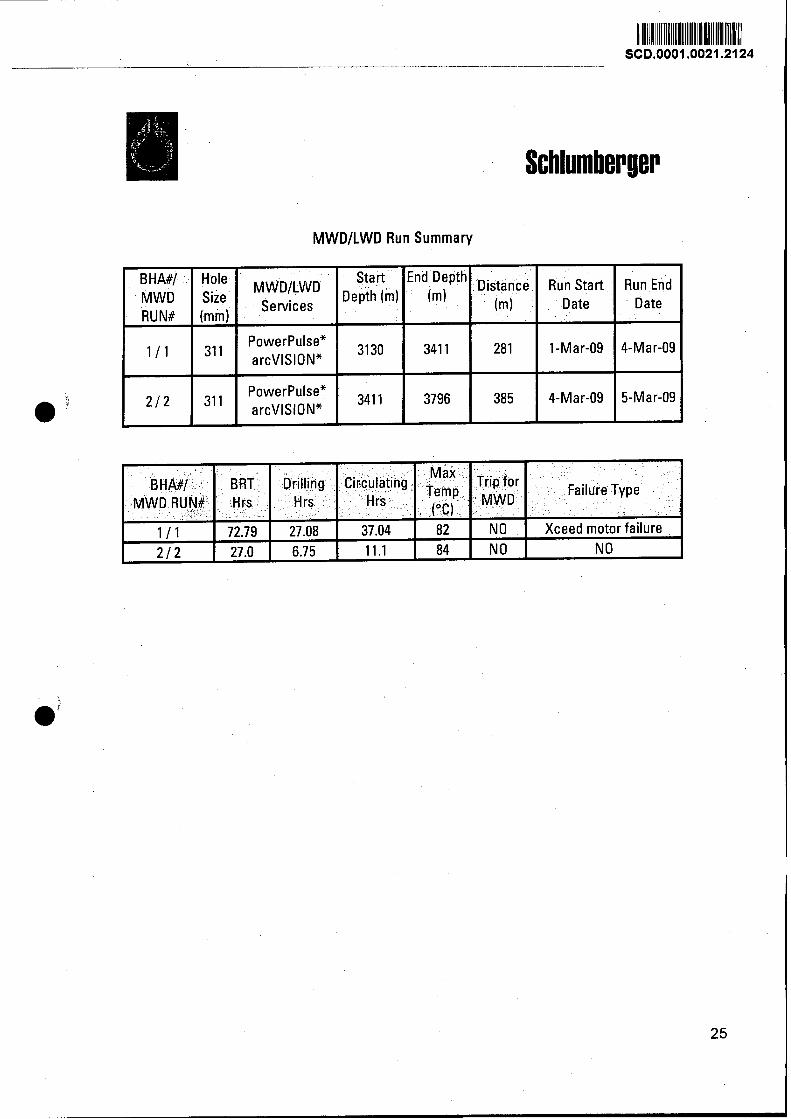
MWDILWD Run Summary
Start End Depth
Size Services
311 1 PowerPulse* arcVISION* 1 3 1 3 0 1 3 4 1 1
PowerPulse* 1 3411 1 311 1 arcVISIONX
3796
Distance (m)
Run Start Date
Run End Date
Failure Type
Xceed motor failure NO
Trip for M W D -
NO NO
Max Temp
. ("C) 82 84
Circulating Hrs
37.04 11.1
Drilling H rs
27.08 6.75
BHA#I M W D RUN#
111 212
BRT Hrs
72.79 27.0

6. BHA Reports
Sc hlumber ger
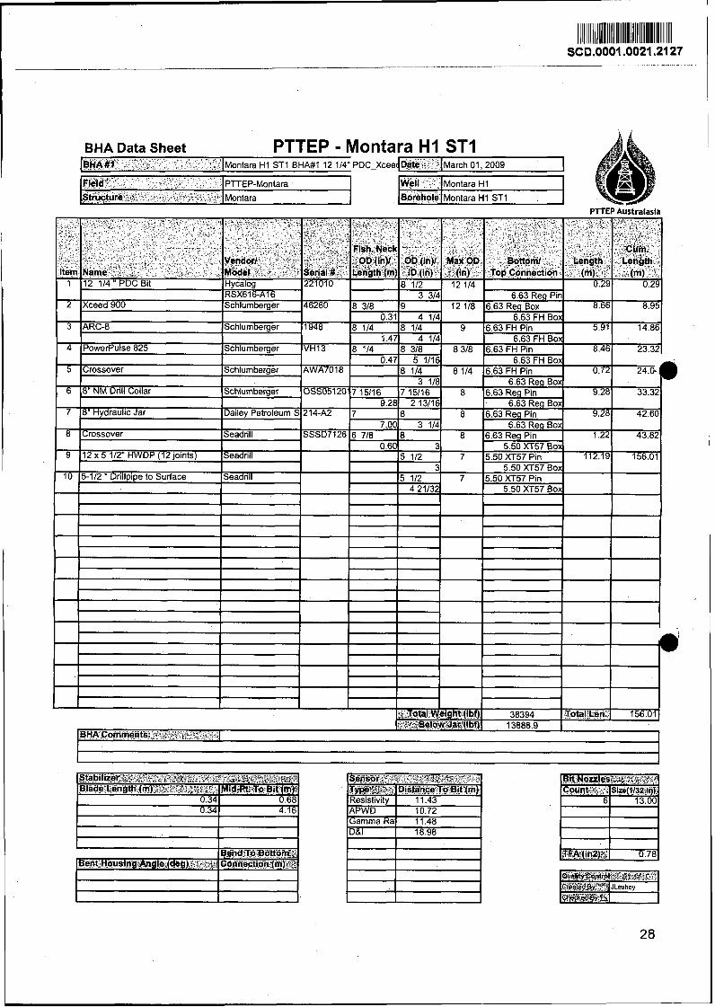
BHA Data Sheet PTTEP - Montara H I ST1 IBHA" ' ". I~ontara H1 ST1 BHA#l 12 114" PDC-Xcee Date I ~ a r c h 01,2009 I Field. . I PITEP-Montara Well l~ontara H1
Structure ' % - -"- - l~ontara A ~oreholel~ontara H1 ST1 - -
PlTEP Australasia
P
Bend To Bottom', Bent Housing Angle (deg) - . , Connection (m) f
5-112 " Drillpipe
12 X 5 112" HWDP (12 joints)
Crossover
8" Hydraulic Jar
8" NM Drill Collar
Crossover
PowerPulse 825
Xceed 900
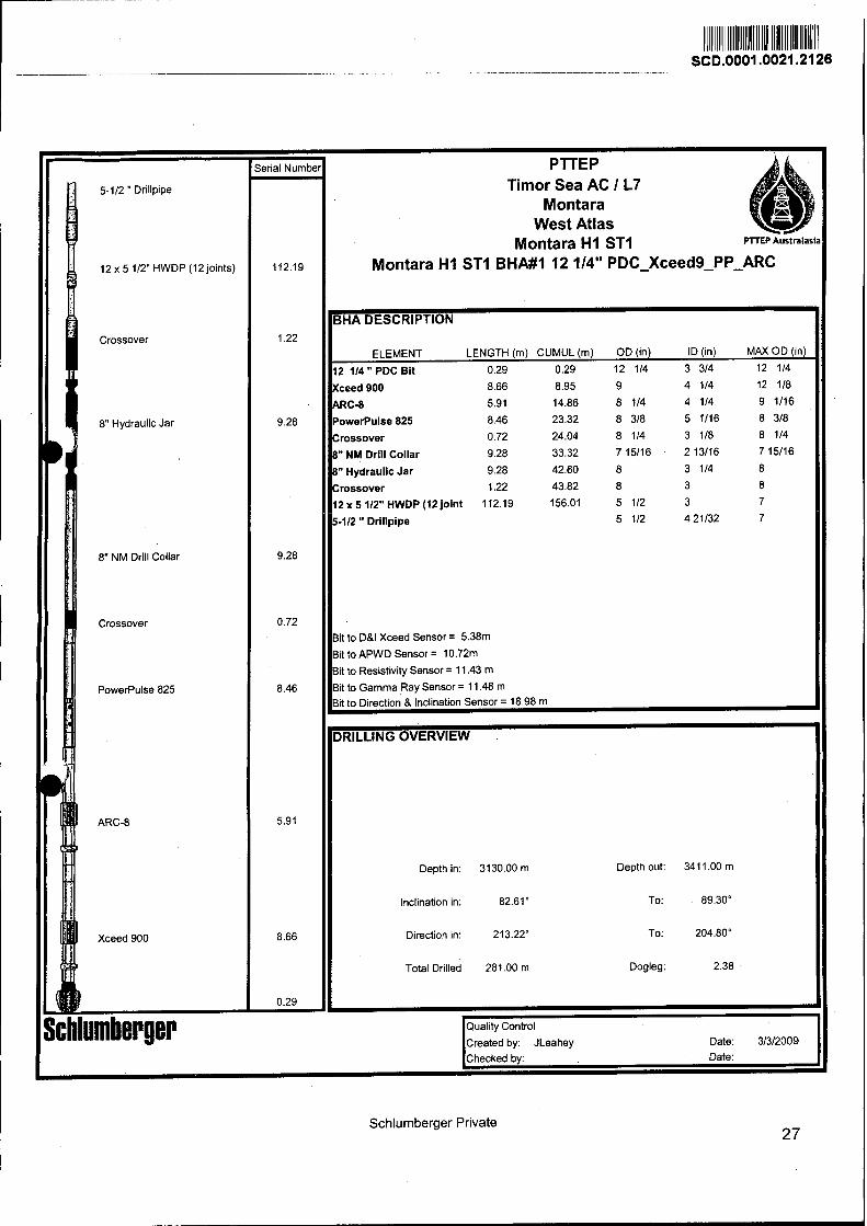
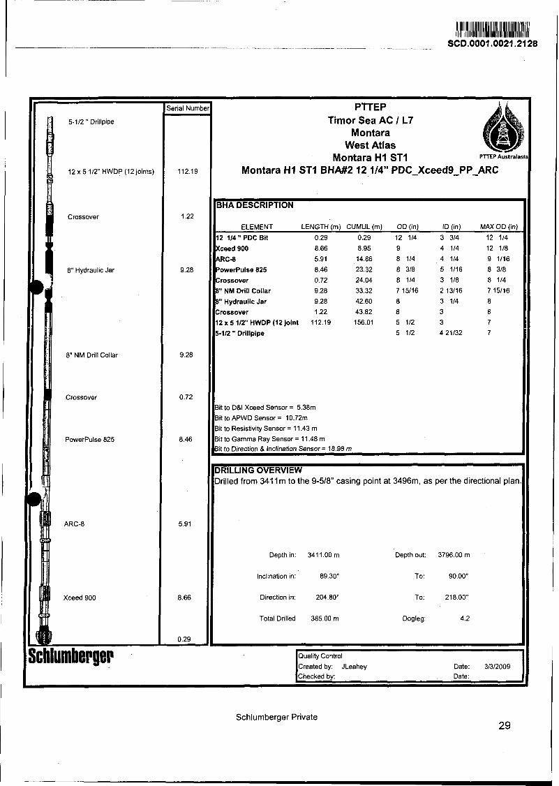
;erial Numb PTTEP Timor Sea AC l L7
Montara West Atlas
Montara H1 ST1 FTTEP Australasl,
Montara H1 ST1 BHA#2 12 114" PDC-Xceed9-PP-ARC
BHA DESCRIPTION I l
ELEMENT LENGTH (m) CUMUL (m) OD (in) ID (in) MAX OD (in)
12 l14 " PDC Bit 0.29 0.29 12 114 3 314 12 114
Xceed 900 8.66 8.95 9 4 114 12 118
ARC-8 5.91 14.86 8 114 4 114 9 1116
PowerPulse 825 8.46 23.32 8 318 5 1116 8 318
Crossover 0.72 24.04 8 114 3 118 8 114
8" NM Drill Collar 9.28 33.32 715116 213116 7 15116
8" Hydraulic Jar 9.28 42.60 8 3 114 8
Crossover 1.22 43.82 8 3 8 12 X 5 112" HWDP (12 joint 112.19 156.01 5 112 3 7
5-112 " Drillpipe
Bit to DBI Xceed Sensor = 5.3811-1
Bit to APWD Sensor = 10.72m
3it to Resistivity Sensor = 11.43 m
Bit to Gamma Ray Sensor = 11.48 m 3it to Direction & lnclination Sensor = 18.98 m
DRILLING OVERVIEW Drilled from 341 1 m to the 9-518 casing point at 3496m, as per the directional plan.
Depth in: 341 1 .OO m Depth out: 3796.00 m I Inclination in: 89.30" To: 90.00"
Direction in: 204.80" To: 218.00" I Total Drilled 385.00 m Dogleg: 4.2
I Quality Control
Created by: JLeahey Date: 3/3/2009 I
Schlurnberger Private 29
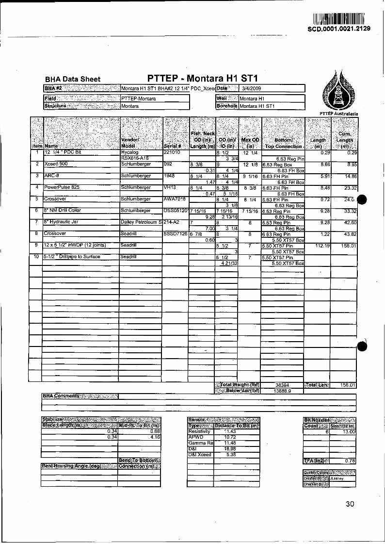
BHA Data Sheet - .
PTTEP - Montara H1 ST1 BHA #2 ' - T-
" Montara H1 ST1 BHA#2 12 114" PDC-Xceec Dare 3/4/2009
&Id -~ . PTTEP-Montara Well - Montara H1
Strjucture Montara sorehole Montara H1 ST1
Sc hlum ber ger
7. Drilling Parameter Sheets
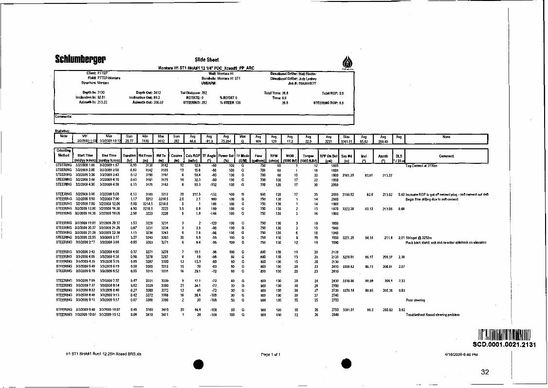
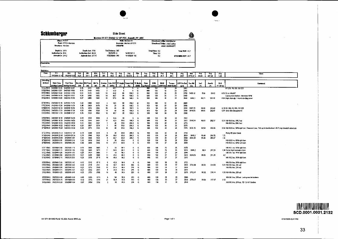
Schlumberger Slide Sheet Montara H1 ST1 B H M I 12 114" PDC-Xceed9-PP-ARC mm..-.-
I Cllent: PTEP Well: Montara H1 Dimctional Drllbr: Matt Blacker
I Reld: PTEPMontara Sln~cturn: Montara
Borehole: Montlra H1 ST1 Dlnctional Driller: Jody Leahey UWIIAW Job I: WAWA0077
1 Depth In: 3130 Depth Out: 3412 Tot Distance: 282 Total Tlme: 28.8 Total ROP: 9.8 Inclination In: 82.61 lncllnaion Out: 89.2 ROTATE: 0 % ROTAT 0 llme: 0.0
Mmuth In: 213.22 Mmuth Out: 205.02 STEERING: 282 % STEER 100 28.8 STEERING ROP: 9.8 I Statlsucs:
None None l Orienting Method StartThne Endllme D u d o n g* Power Set TF Mode Flow RPM WOE Torque SPP On Bot Svy Md lncl Comment
(mldlyv h:mm) (mldlyy h:mm) (hr) l% (GIM) (nalhnln) (dminl (1000 bfl (1060 Rbf) (psi) (m) STEERING 3/2/2009 l:W 3/2/2009 157 0.95 3130 3142 12 12.6 -60 100 G 750 60 1 12 1800 Tag Cement at 3130m STEERING31212009200 312/20092:50 0.83 3142 3155 13 15.6 -60 100 G 700 60 1 18 1800 STEERlNG312120093:36 31212009343 0.12 3155 3161 6 51.4 -60 loo G 700 60 15 22 1800 3161.29 82.61 213.22 STEERING 3/2/2009 3:44 3/2/20094:10 0.43 3161 3175 14 32.3 -60 100 G 700 100 17 22 1950 STEERING 31212009430 312/20094:39 0.15 3175 3183 8 53.3 -132 100 G 700 120 17 30 2000
STEERING 3/2/2009 500 3/2/2009 5:08 STEERING 31212009 550 3/2/2009 7:00 STEERING 3/2/2009 7:00 3/2/2009 1200 STEERING 3/2/2009 12:OO 3/2/2009 16:30 STEERING 3/2/2009 1630 3/2/2009 1905
2000 3190.52 82.9 213.52 0.43 lmrease ROP to get off cement plug - sofl cement not defl 2000 Begin time dnlling due to roRcemen1 1900 1870 3222.38 83.13 213.06 0.48 1900
STEERING 3/2/2009 1905 3/2/2009 2037 STEERING 3/2/2009 20:37 3/2/2009 21:29 STEERING 3/2/2009 21:29 3/2/2009 2238 STEERING 3/2/2009 2255 31312009 L17 STEERING 3/3/2009 237 3/3/2009 308
l800 1940 1940 1950 3251.25 84.14 211.4 2.01 Stdnger@ 3252111 1990 Rack backstand, exit and re-enter sidetrack on elevators
STEERING 31312009 3:43 313120094:05 0.37 3271 3278 7 19.1 -96 100 G 800 130 15 20 2120 STEERING 3/3/2009 405 31312009 4:35 0.50 3278 3287 9 18 -96 60 G 800 130 15 20 2120 3279.81 85.17 209.37 2.38 STEERING 31312009435 31312009 526 0.85 3287 3300 13 15.3 4 0 60 G 800 130 15 20 2130 STEERING 3/3/2009 549 31312009 6:19 0.50 3300 3315 15 30 -60 60 G 850 130 20 23 2410 3309.82 86.73 208.01 2.07 STEERING 3/3120096:19 31312009652 0.55 3315 3331 16 29.1 -72 60 G 850 130 20 23 2410
STEERING 31312W97:W 313120097337 0.47 3331 3339 B 17.1 -72 60 G 850 130 20 24 2430 3339.86 88.08 206.1 2.33 STEERING 31312009 7:37 36112009 8:14 0.62 3339 3360 21 34.1 -72 30 G 900 130 30 26 2700 STEERING 31312009 8:32 31312009 8:48 0.27 3360 3372 12 45 -72 30 G 900 130 30 27 2720 3370.14 88.65 205.35 0.93 STEERING 3/3120098:48 3/3/2009 913 0.42 3372 3388 16 38.4 -108 30 G 900 130 30 27 2740 STEERING 313120099:13 3/3/20099:17 0.07 3388 3390 2 30 -108 50 G 900 130 35 25 27% Poor steering
STEERING 313120099:40 31312009 10:07 0.45 3390 3410 20 44.4 -108 50 G 900 130 35 26 2750 3391.01 89.2 205.02 0.92 STEERING 31312009 10:07 31312009 1012 0.08 3410 3411 l 24 -108 100 G 900 130 22 26 2840 Troubleshoot Xceed steering pmMem
H1 ST1 BHM1 Run1 12.25in Xceed BRS.xls Page 1 of 1

Schlumberger
8. Drilling Tool Run Reports
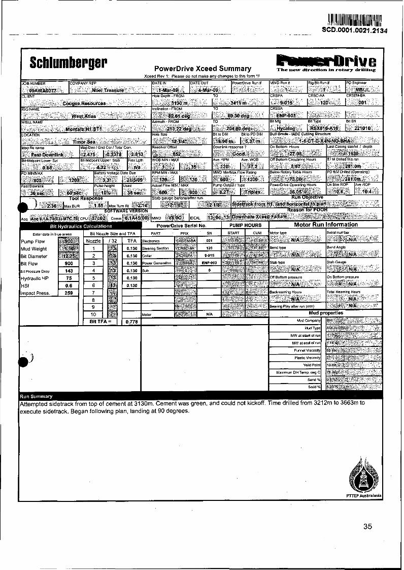
PowerDrive Xceed Summary The new dlrecllon in rotary drilling Xceed Rev 1 Please do not make any changes to thls foml 1 1 1
xecute sidetrack. Began following plan, landing at 90 degrees.
,,L -.. Coogee Resources
PD Englneer
. MBlJL - 8 IENT lHnb Omth - FROM TO ICRSPA CRSC-AA CRSEMBA
Ilnclnahan - FROM TO ICRSSA
- 3130 m I 3411 m ,
MWD Run #
~ ~ , > l +
R I ~ 611 Run # A - - %;'l .
DATE OUT
4-~a"r-09 DATE IN
,t-rular& ,,
JOB NUMBER
09AW~0077
9-015
PowerDnve Run #
I , l S* -. - COMPANY REP ".
c Noel Treasure
120-- I 001
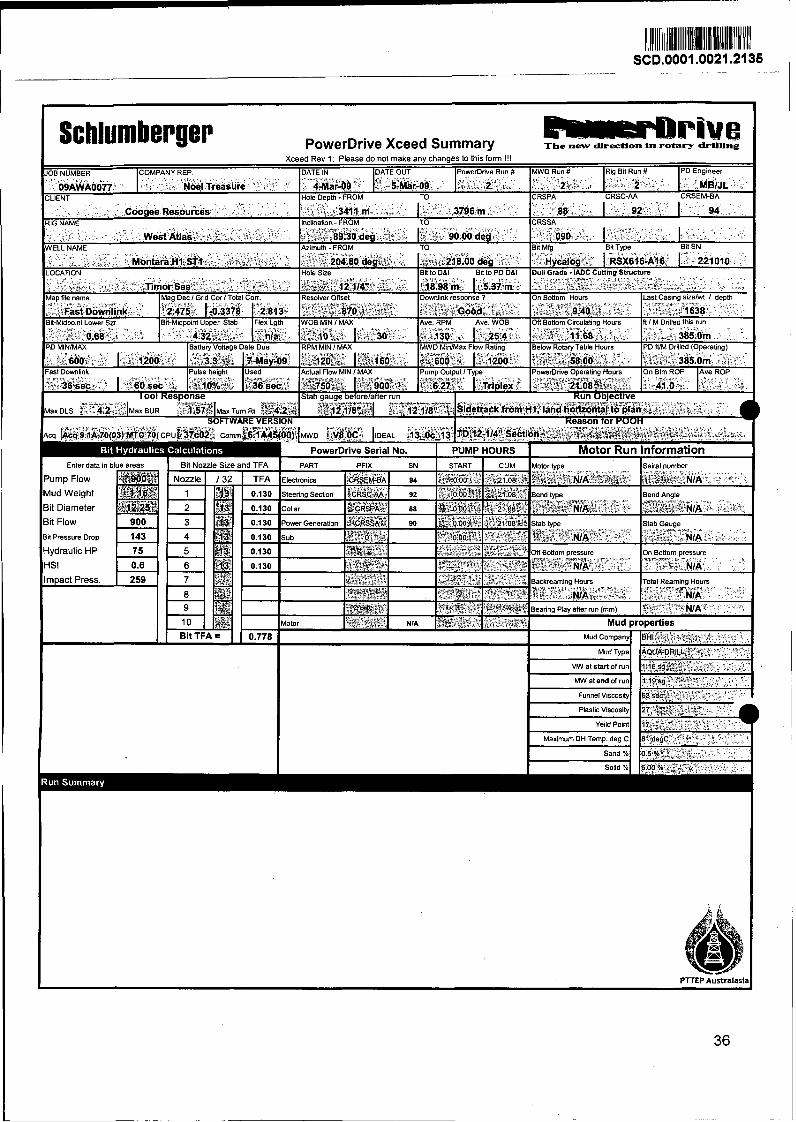
Schlumberger PowerDrive Xceed Summary k r r e P B ~ h t 0 The new .., directlon .. + Ln rotary drtl-
3it Diameter
lit Pressure Dmp
I Funnel Viscosity
Maximum DH Temp. deg C
Sand % U
P T E P Australasia

9. Dull Bit Grading
Schlum ber ger
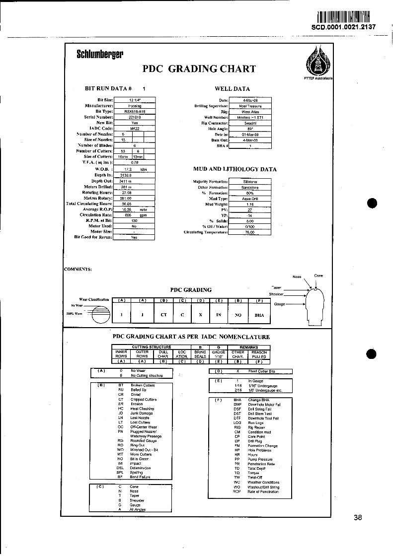
Schlurnberger PDC GRADING CHART
BIT RUN DATA # 1 WELL DATA
Bi t S i x
Manufacturer: Date:
Serial Number: Well Number: Montara H I ST1
Rig Contractor:
Hole Angle: Number o f Nozzles: Date in: 01-Mar49
Size o f Nozzles: Date Out: 4-Mar49
Number o f Blades: BHA #
Number o f Cutters:
Size o f Cutters:
T.F.A. ( sq ins ):
W.O.B. :
Depth In:
Depth Out:
Meters Drilled:
Rotating Hours:
Metres Rotary:
o ta l Circulating Hours:
Average R.0.P:
Circulation Rate:
R.P.M. a t Bit:
Mo to r Used:
M o t o r Size:
B i t Good for Rerun:
MUD AND LITHOLOGY DATA
Majority Formation: Siltstone
80%
Mud Type: Aqua-Drill
Mud Weighf:
PV: YP:
% Solids: 5.00
% Oil / Water: 011 W :ulating Temperature: 76.00
3MMENTS:
Nose
PDC GRADING CHART AS PER IADC NOMENCLATURE
PDC GRADING Taper . Shoulder
Wear Cisrsification ( A )
No Wear
30% Worn
Broken Cutters BU Balled Up CR Cored CT Chipped Cutters ER Erosion HC Heat Checking JD Junk Damage LN Lost Nozzle LT Lost Cutters OC oftKenter Wear PN Plugged Noulel
Waterway Passage RG Rounded Gauge R 0 Ring Out WO Washed Out - Bit WT Wom Cutters NO Bit is Green IM Impact
DEL Delaminatmn SPL Spalling BF Bond Failure
1 C T C X I N N O BHA ' F ) G a u g e z D
( A )
CUlTlNGSTRUCTURE
I I - "
2/16 118" Undergauge etc.
B BRING SEALS
INNER ROWS
( C ) C Cone N Nose T Taper S Shoulder G Gauge A All Angles
( B )
OUTER DULL LOC ROWS CHAR. ATION.
( A U A F
( F ) BHA Change BHA DMF Domhole Motor Fall DSF Drill String Fail DST Dnll Stem Test DTF Downhole Tool Fail LOG Run Logs RIG Rig Repair CM Condiiion mud CP Core Point DP Drill Plug - FM Formation Change HP Hole Problems HR Hours PP Pump Pressure PR Penetration Rate TD Total Depth TQ Torque TW Twist-oft WC Weather Conditions WO WashouffDrill String ROP Rate of Penetration
G GAUGE
1116"
( A ) 0 NoWear 8 No Cutting structure
( C )
m) X Fixed Cutter Bits 1
REMARKS
I ( E l 1 In Gauae 1
( 0 )
OTHER CHAR.
REASON PULLED
( E ) ( B )
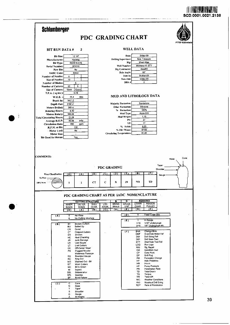
Schlumberger PDC GRADING CHART
BIT RUN DATA # 2 WELL DATA
Bit Size: Manufacturer:
Bit Type: Serial Number:
New Bit: IADC Code:
Number of Nodes: Size of Nozzles:
Number of Blades: Number of Cutters:
Sim of Cutters: T.F.A. ( sq ins ):
W.O.B. : Depth In:
Depth Out: Meters Drilled:
Rotating Hours: Metres Rotary:
'otal Circulating Hours: Average R.0.P:
Circulation Rate: R.P.M. at Bit:
Motor Used: Motor SW:
Bit Good for ~ e r u n : l Yes
OMMENTS:
Date:
Rig ~0ntractor:I S;: 1 Hole Angle:
Date Out: BHA U
MUD AND LITHOLOGY DATA
Other ~ormation:l SiRstOne 1 % Formation: 1M)%
Majority Formation:
Mud ~ ~ ~ e : l Aqua-Drill j
Sandstone
Mud Weight:
o,& s o ~ d ~ ~ ~
% Oil l Water: 011 00
Circulating Temperature: 81.00
PDC GRADING
m Australasl
Nose 'One
CT ER HC JD LN LT OC PN
RG R0 WO WT NO IM
DEL SPL BF
( B )
Chipped Cutters Erosion Heat Checking Junk Damage Lost Nozzle Lost Cutters Off-Center Wear Plugged Noulel Waterway Passage Rounded Gauge Ring Out Washed Out - Bit Wom Cutters Bit is Green impact Delaminatton Spailing Bond Failure
( E )
L
Taper Shoulder
G Gauge
( D )
m*/. worn 3. Wear Clasrificallon No \Venr
REMARKS CURING STRUCTURE
( F ) BHA Change BHA DMF Downhole Motor Fail
B BRING SEALS
( D )
OTHER CHAR.
DULL CHAR.
PDC GRADING CHART AS PER IADC NOMENCLATURE
( F )
G GAUGE
1 1
( E )
REASON PULLED
LOC ATION.
DSF Drill String Fail DST Drill Stem Test DTF Downhole TWl Fail LOG Run Logs RIG Rig Repair CM Condition mud CP Core Point DP Drill Plug FM Formation Change HP Hole Problems HR Hours PP Pump Pressure PR Penetrati~n Rate TD Total Depth TQ Toque TW Twist-Off WC Weather Conditions WO WashouVDrill String ROP Rate of Penetration
TD
( C )
( B ) I ( F ) ( B ) I ( C ) .
( A ) o NO Wear 1 c D ) X Flxed Cuner Bits 1 8 No Cutting structure
( E ) 1 In Gauge
NO
( B (A )
( B ) BT Broken Cutters BU Balled Up CR Cored
IN
( A )
1116 1116" Undergauge 2/16 118" Undergauge etc.
X C CT 1 1
10. Service Quality Issues
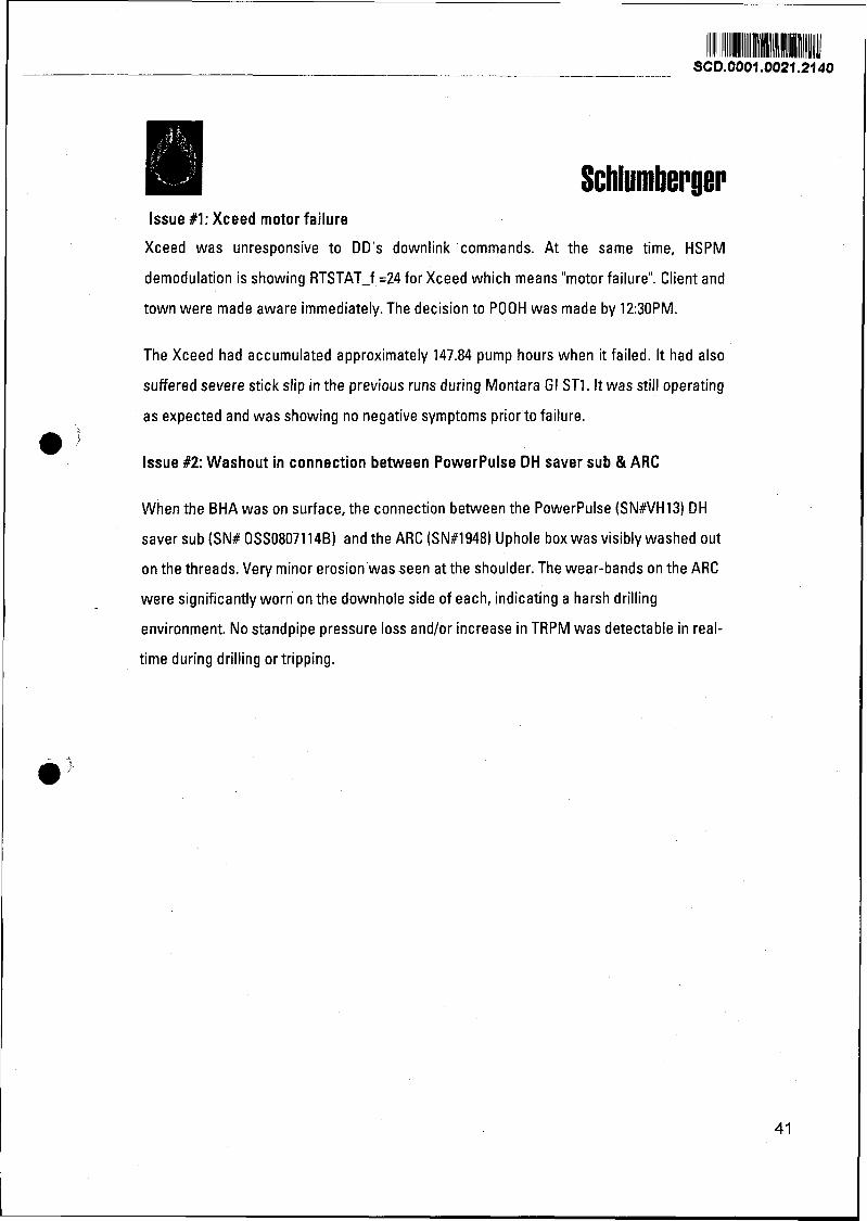
lssue #l: Xceed motor failure
Xceed was unresponsive to DD's downlink commands. At the same time, HSPM
demodulation is showing RTSTAT-f =24 for Xceed which means "motor failure". Client and
town were made aware immediately. The decision to POOH was made by 12:30PM.
The Xceed had accumulated approximately 147.84 pump hours when it failed. It had also
suffered severe stick slip in the previous runs during Montara GI ST1. It was still operating
as expected and was showing no negative symptoms prior to failure.
lssue #2: Washout in connection between PowerPulse DH saver sub & ARC
When the BHA was on surface, the connection between the PowerPulse (SN#VH13) DH
saver sub (SN# OSSO8071 l4B) and the ARC (SN#1948) Uphole box was visibly washed out
on the threads. Very minor erosion was seen at the shoulder. The wear-bands on the ARC
were significantly worn on the downhole side of each, indicating a harsh drilling
environment. No standpipe pressure loss andlor increase in TRPM was detectable in real-
time during drilling or tripping.
Schlum berger
11. Depth Control Summary
Schlumberger Depth Control Summary
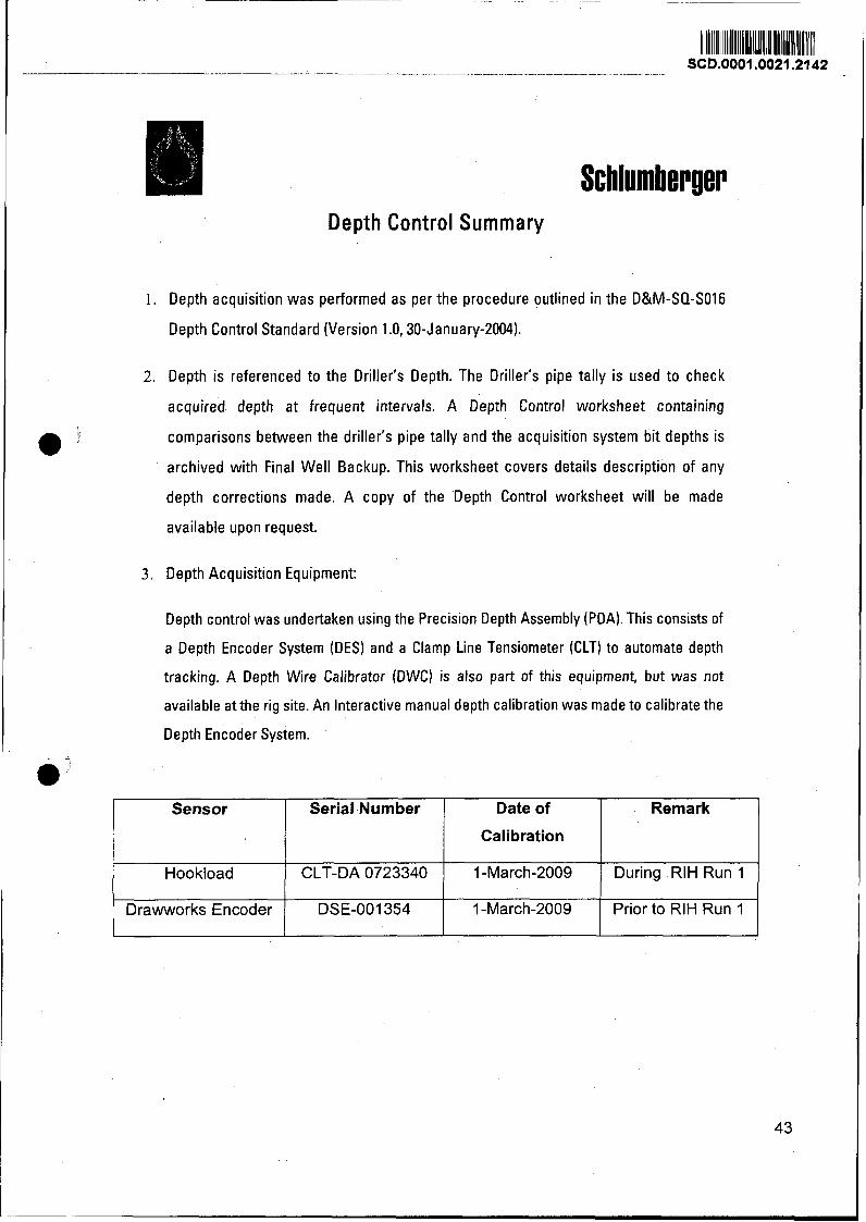
1. Depth acquisition was performed as per the procedure outlined in the D&M-SO-SO16
Depth Control Standard (Version 1 .O, 30-January-2004).
2. Depth is referenced to the Driller's Depth. The Driller's pipe tally is used to check ~ acquired depth at frequent intervals. A Depth Control worksheet containing
0 ' comparisons between the driller's pipe tally and the acquisition system bit depths is
archived with Final Well Backup. This worksheet covers details description of any
depth corrections made. A copy of the Depth Control worksheet wil l be made
available upon request.
3. Depth Acquisition Equipment:
I Depth control was undertaken using the Precision Depth Assembly (PDA). This consists of
a Depth Encoder System (DES) and a Clamp Line Tensiometer (CLT) to automate depth
tracking. A Depth Wire Calibrator (DWC) is also part of this equipment, but was not
I available at the rig site. An Interactive manual depth calibration was made to calibrate the
I Depth Encoder System. l
mi Sensor
Hook load
Drawworks Encoder
Date of
Calibration
1 -March-2009
1 -March-2009
Serial Number
CLT-DA 0723340
DSE-001354
Remark
Dur ing R I H R u n 1
Pr ior t o R I H R u n 1
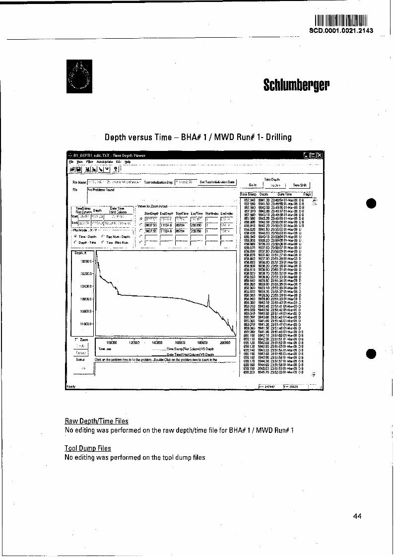
Depth versus Time - BHA# 1 / MWD Run# l - Drilling
[ r Zoom
9
Raw Deothnime Files No editing was performed on the raw depthltime file for BHA# 1 / MWD Run# l
Tool Dump Files No editing was performed on the tool dump files
Schlumberger
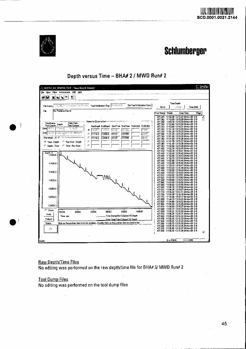
Depth versus Time - BHA# 2 / M W D Run# 2
me Stanpr Depth Dale Tme Flqls
4772m1119040131527MMar-09DB r
Raw Deothnime Files No editing was performed on the raw depthhime file for BHA# 31 MWD Run# 2
Tool Dumo Files No editing was performed on the tool dump files
Schlumber ~ e r
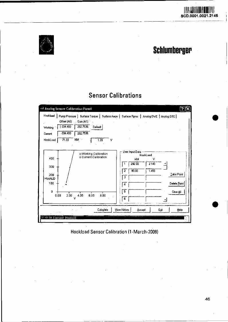
Sensor Calibrations
P- --
h ~ k ~ o a d 1 Pump Pressure I Surface Torque 1 Surface Amps 1 Surface Rpms Analog DWE 1 Analog GTE ) Offset [AO) Gain [All
HookLoad 1- klbf 11.39 V
/ o Working Calibration
400 -- o Current Calibration
300 --
200 -- HookLD
100 --
0 I I l l
0.00 2.00 4.00 6.00 8.00 v
lake Po~nt 1
Calcglate 1 Y i w History 1 Accept I E+ I Help I
Hookload Sensor Calibration (1-March-2009)
Schlumberger
Hookload Pump Pressure f Surface Torque ) Sudacehps 1 Surface Rprns 1 Analog DWE 1 Analog GTE 1 , I l
Offset (AO] Gain (AI)
Working Default /
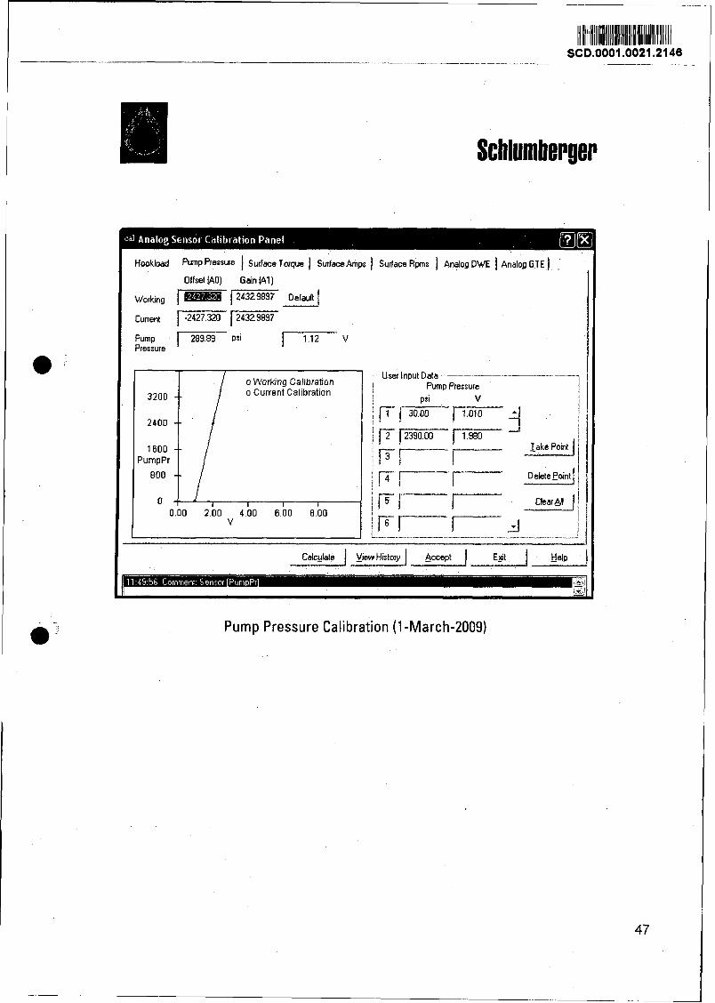
Pump 1 psi Pressure
o Working Callbratton o Current Calibrat~on
1600 PumpPr
F I ' clear AII J
Calcble I yieu History / Accept Egt I Help
- P -
Pump Pressure Calibration (1-March-2009)
Schlum ber ger
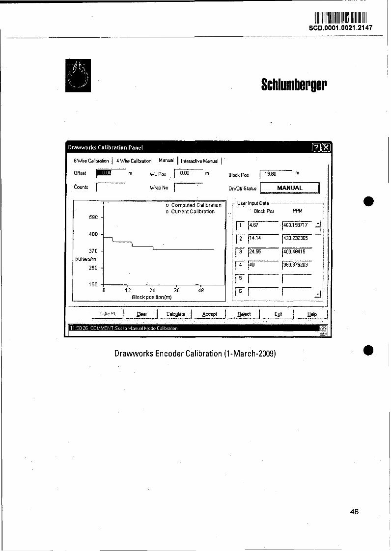
6 Wire Calibration 1 4 Wire Calibration Manual 1 Interactive Manual f
e t 1- m WLPOS p- m BIOCL POS 1- m
WrapNo I-" Ontoff Status MANUAL Counts 1
o Computed Callbration o Current Calibration
1 '2 2'4 36 4'8 I
Block ~ositiontm)
User Input Data
Block Pos PPM
Drawworks Encoder Calibration (1 -March-2009)
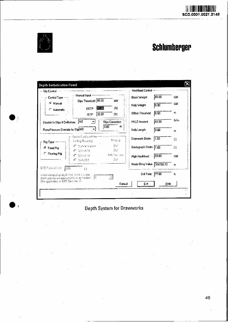
Slip Control ,.. Manual Input
1.. Control Type ---7 I i i / Slips Threshold 185.DD klbf 1 c Manual ! :
! i -. -I--..--.--i
Disable In Slips If OnBottom: NO Slips Correction i ' f i m j
~ump~ressure override f o ~ s l i p [ , -. -- - - -.-v . .. - -- - v-., .- .... -
Rig Type I
@ Fixed Rig j Floating Rig I
-
r Hookload Control
i Block Weight [ klbf l
1 Kelly Weight I i
1 Offbot Threshold 1050 m i
/ Kelly Length m
1 1 ' Geolograph D~rctn 1.00 i , j- [ l
Default I [F] Help
Depth System for Drawworks