Embed Size (px)
Citation preview

OF INQUIRY MONTARA WELL HEAD PLATFORM
UNCONTROLLED HYDROCARBON RELEASE
COMMONWEALTH OF AUSTRALIA
DECLARATION UNDER THE STATUTORY DECLARATIONS ACT 1959
I, Craig Neil Duncan of care of Level 1, 162 Colin Street, West Perth in the State of Wester11 Australia, Well
Construction Manager, make the following declaration under thestatutory Declarations Act 1959 (Cth) as
follows:
Table of topics - Craig Du~lcan
Topic Porograplzs
l Current position
I
2-3
Qualifications and work experience
Montara Development Project
4-5
6-8
Atlas Drilling 9-12
My responsibilities 13-15
I
The well construction team, their qualifications and roles
l
16-23
Co~nniunication within PTTEPAA
Co~n~nunication with Atlas Drilling
24-28
29-33
I
Knowledge of the key docu~nents
Key documents to manage the H1 Well
l
34-59
Changes to the DP 60-64
l
CND
Drilling terminology
I
67
Cementing 68-1 12
WIT.1000.0001.0063

OF INQUIRY MONTARA WELL HEAD PLATFORM
UNCONTROLLED HYDROCARBON RELEASE
Pore pressure & fracture pressure - H1 Well
Hydrostatic pressure
Drilling, displacement & completion fluids
Barriers
Temporary and long term suspension
1-11 Well specifics:
The cementing plan for the 2441nm (95/<) diameter casing
Change cement plug to pressure containing corrosion cap - H1 Well
March 2009
The 340mm (13 g") PCCC
Suspension status of the H1 Well and the plan for the completion of the wells
20 August 2009
21 August 2009
Specific questions raised by the Co~n~nission
Possible explanation of the cementing issues arising on 7 March 2009
installing 2441nm (5%") casing into H1 Well 011 6 & 7 March 2009
Cement calculations
Pressure testing casing
Waiting on cement
Testing shoe cement integrity
Pressure testing PCCC's - permanent and tested barrier
CND
WIT.1000.0001.0064

OF INQUIRY RIOWARA WELL HEAD PLATFORY
UNCONTROLLED HY1)ROCARUON lWI.I<ASE
356-359 34.
I I
1 I make this declaration i n response to the request from the Montara Conimission of Inquiry (the
Conmission) into the uncontrolled release of oil and gas fsom the Monlara Wellhead Platform in the
Timor Sea to provide evidence in relation to specified areas of interest relevant to the Commission's
Terms of Reference.
Absence of a 340m1n (13 %") PCCC
I I
Current position
360-366 35.
2 I am engaged by PTTEP Australasia (Ashmore Cartier) Pty Limited (PTTEPAA) as the Well
Construction Manager and have been in that position since about June 2007.
Re-installing the 2441nm (5%") PCCC
367-372 36.
3 I am the Well Construction Manager for PTTEPAA's Montara Development Project.
Communications issues
Qualificatioas and work experience
4 I have extensive experience in the oil and gas industry and I hold a Graduate Diploma (obtained in
about October 2001) and Graduate Cestificate in Petroleum Engineering (obtained in about April
2005) fsom the University of New South Wales.
5 My work experience is as follows:
I stasted work in the oil and gas industry on 16 November 1977 as a roustabout;
From 1977 until 1986 I worked my way up through various positions for drilling contractors;
From 1986 to 1990 I worked in the gold mining industry starting a company that
manufactured carbon regeneration kilns;
In 1990 1 returned to the oil and gas industry and worked for a drilling contractor as a driller
in Brunei;
From 1992 to 1993 I worked for a specialist drilling company dedicated to opthising
drilling techniques in extended reach wells;
CND
WIT.1000.0001.0065

O F INQUIRY MONTARA WELL HEAD PLATFORM
UNCONTROLLEDHYDROCARBONRELEASE
(0 In 1993 1 joined Apache Energy Limited as a consultant in Perth, initially as a drilling
supervisor offshore and eventually as a drilling superintendent;
(g) From July 2006 to October 2006 I completed a number of small consulting jobs before
joining Oil Search in October 2006 in a staff position to work on a two well program
offshore Yemen as drilling superintendent. This campaign was successfully completed in
2007:
(h) I left Oil Search in May 2007 and joined PTTEPAA (then Coogee Resources) as Well
Construction Manager in about June 2007.
The Montara Development Project
6 I'TTEPAA is developing the Montara, Skua, Swift/Swallow Fields i n the East Timor Sea. The
development of these fields is referred to as the Montara Development Project and is located about
690 km west of Darwin, Northern Territory, near the Ashmore Cartier reef.
The Montara Development Project involves four production wells including the HI-STI well (H1
Well), in the Montara Field, two production wells it1 the Skua Field and three production wells in the
SwiftISwallow Field.
8 The Montara Development facilities include a wellhead platform (WHP) at the Montara Field.
Atlas Drilling
9 Shortly before I was engaged by PTTEPAA, Atlas Drilling (S) Pte Ltd (Atlas Drilling) was
contracted by PTTEPAA for the Montara Drilling campaign, including the construction of the H1
Well, on the Montara WHP.
10 Atlas Drilling owns the West Atlas jack-up drilling rig (WestAtlas), which is a type of Mobile
Offshore Drilling Unit (or MODU).
1 1 Atlas Drilling is part of the Seadrill group of companies headquartered in Norway. The jack-up rig
division is based in Singapore.
12 The Seadrill office in Singapore provided centralised support to the rigs in the Asia Pacific region,
including the West Allas. This support included operations management, marketing, marine and
engineering expertise plus HSE and accounting functions.
WIT.1000.0001.0066

OF INQUIRY MONTARA WELL HEAD PLATFORM
UNCONTROLLED HYDROCARBON RELEASE
My responsibilities
13 When I was engaged by PTTEPAA 1 reported to the Project Managcr of the Montara Development
Project. Initially that was Duncan Clegg and from about JanuaryIFebruary 2009 it was Narangpol
Solo Suthapintu. Since 21 August 2009 1 have reported directly to PTTEPAA's Chief Operating
Officer (COO) Andy Jacob (Mr Jacob).
14 My responsibilities now, and at all times since I was engaged by PTTEPAA, include the management
and supervision of well operations including:
(a) designing wells;
(b) preparing well programs;
(c) establishing contracts, procuring equipment and organising logistics; and
(d) risk and change management
15 Whenever the Wesl Atlas was working on the Montara Development Project, either Chris Wilson,
PTTEPAA's Drilling Superintendent, or I was on call 2417.1 was on call for about 10 days a month
and MS Wilson was responsible for 20 days a month. I would also physically visit the West Atlas and
W1-IP, about every 2 to 3 months in order to see for myself how operations were progressing and to
maintain visibility and relationships with the offshore personnel.
The well const r~~ct ion team, their qualifications and roles
16 When I was engaged by PTTEPAA the core of the well construction team existed. Chris Wilson liad
been with PTTEPAA for about six months and PTTEPAA had a logistics co-ordinator who had been
with PTTEPAA for a number of years. PTTEPAA also liad a team of completions engineers.
However, in order to prepare for and undertake the drillir~g campaign of the Montara Development
Project it was necessary to recruit a number of other people.
17 1 was involved in the recruitment of these additional members of the well constructiontea~n
18 Members of PTTEPAA's well construction team were recruited on the basis of their experience and to
ensure that the team had a variety of skills available to it.
19 After consulting with PTTEPAA's exploration manager, I initially recruited an operations geologist in
about June-August 2007. He had excellent experience with geosteering, a skill we expected to require.
C N D
WIT.1000.0001.0067

OF INQUIRY MONTARA WELL HEAD PLATFORM
UNCONTROLLED HYDROCARBON RELEASE
20 I was involved in the hiring of two graduate engineers, the first in December 2007 and the second in
November 2008.
21 As to drilling supervisors:
Paul O'Shea was contracted in November 2007 and spent about two months i n PTTEPAA's
West Perth office before co~n~nencing an offshore rotation as a senior drilling supervisor;
other drilling supervisors were contracted as required to support drilling operations. Noel
Treasure and Craig Klumpp commenced in March 2008 and Lindsay Wishart in April 2008.
Brian Robinson was engaged in March 2009;
the drilling supervisors were selected for their experience which was varied. Noel Treasure,
Paul O'Shea and Lindsay Wishart had all worked as drilling supervisors in the past. Craig
Klu~npp and Brian Robinson had not worked as drilling supervisors but had both worked in
senior positions with drilling contractors; and
the drilling supervisors each had between 12 and 30 years oil field experience. In addition to
experience, each drilling supervisor was required to have a current well control certificate and
a current HUET (Helicopter Underwater Escape Training) card.
22 The PTTEPAA people who reported to me were:
Chris Wilson -Drilling Superintendent
Keith Brand - Senior Completions Engineer
Richard Stear - Operations Geologist
Chris Glennon -Procurement & Logistics Coordinator
Angus Meredit11 - Conipletions Engineer **
Gary Watkins - Completions Engineer **
Mathieu Higgins - Drilling Engineer ***
Steven Loveless - Drilling Engineer ***
Natalie Scarffe - Shorebase Coordinator - Darwin
WIT.1000.0001.0068

O F INQUIRY MONTARA WELL HEAD PLATFORM
UNCONTROLLED HYDROCARBON RELEASE
Lisa Lam -Procurement & Logistics Assistant
Noel Treasure - Senior Drilling Supervisor *
Paul O'Shea - Senior Drilling Supervisor *
Lindsay Wishart - Drilliug Supervisor *
Craig Klu~npp - Drilling Supervisor *
Briau Robinson -Drilling Supervisor *
23 The usual work rosters for the above people were as follows:
* Worked offshore on a 21 day rotation.
** Worked both in the office and offshore as required.
*** Worked offshore for 21 days plus one week it1 tlie office.
Co~n~nunication within PTTEPAA
24 There were three main forms of cotnmunication within tlie well construction team. They were email,
telephone and face to face meetings. The followiug co~nmunicatiot~ took place between PTTEPAA and
Atlas Drilling personnel, in accordance with PTTEPAA's WCMS -Construct, Services or Abandon
Well Process, Activity 4.1.4, Tasks 3 and 4 of the Cotistruct, Service or Abandon Well Process
standard or manual (Process Manual) (ie Construct, Service or Abandon Well Process Mauage~nent
Standard - D41-502434 Rev 2; 13 March 2009):
(a) Email commuiiications were common:
0 )
(ii)
(iii)
the main email of significance was the provision of daily reports from the West Atlas
This email included the Daily Drilling Report (DDR), mud reports, bulk reports and
the daily Personnel On Board (POB) list. It also included a description of what was
going on which was intended to be background to the day's activities;
this etnail went to a number of people within the well construction team;
another important email was the 7 day look ahead wliicli was geuerated on tlie West
Atlas by the PTTEPAA drilling engineers. This spreadsheet outlined the next seven
W P
WIT.1000.0001.0069

OF INQUIRY MONTARA WELL HEAD PLATFORM
UNCONTROLLED HYDROCARBON RELEASE
days' plans for well construction, personnel movements and vessel/helicopter
movements;
(iv) this email went to an extensive distribution list including third party contractors and
Atlas Drilling; and
(v) the person responsible for day to day operations, either Mr Wilson or I depending on
who was on duty, would also generate a morning update etnail intended to give a oue
page summary of what had happened the day before and what was planned. This was
distributed widely to PTTEPAA, Atlas Drilling and third pasty contractors. There
were also a number of eniails throughout the day as in any organisation;
(b) telephone calls were less formal:
(i) there was a scheduled morning call between the West Atlas and the person responsible
for day to day operations, either Mr Wilson or I, depending on who was on duty. This
call was a review of events and plans and normally took about 15 minutes;
(ii) nonnally there was an afternoon or evening call to the West Atlas as well;
(iii) calls to and from the West Atlas were generally to the Senior Drilling Supervisor,
either Mr O'Shea or Mr Treasure depending on who was on duty; and
(iv) telephone calls to Atlas Drilling personnel (generally to the West Atlas Manager Mr
Millar) were not scheduled but took place on average at least once each day between
either Mr Wilson or me; and
(c) meetings were held at 0900 WST every week day morning at PTTEPAA's project office in
Perth:
(i) the morning meeting would include the well construction team in the office@
onshore), MS Millar plus invited third pasty contractors on an as required basis; and
(ii) people attending this meeting had normally already read the nionling update etnail.
These meetings were an opportunity to brain storm problems and ensure that all were
involved and aligned for the days work. The morning meeting normally took between
20 minutes and 1 hour. The meeting reviewed the past 24 hours operations and
reviewed operations planned for the next few days. Once the drilling discussion was
Q v 9
WIT.1000.0001.0070

OF INQUIRY MONTARA WELL HEAD PLATFORM
UNCONTROLLED HYDROCARBON RELEASE
complete, each person at the meeting had the opportunity to discuss what they had
been working 011 or to raise any issues of concern.
During operations on the West Atlas, the PTTEPAA drilling supervisors prepared a forward plan to
communicate requirements to the crew and service companies. These plans were updated as events
changed and generally only covered the next day or so of operations. Each plan is shown to Atlas
Drilling's Offshore Installation Manager (OIM) on the West Atlas for his comment and confirmation
before it is issued. The WCMS (described below) refers to these plans as Instructions To Drillers.
Tile plans are not nomally sent to PTTEPAA's office for review.
When not on board the WHP and West Atlas I received a number of reports from the West Atlas in
order to monitor and supervise the operations. The main repoll was the DDR.
The DDR includes a description of critical path or online events with respective durations rounded to
the nearest 30 minutes. It also includes basic information concerning safety, materials, drilling
equipment and drilling parameters. The DDR is similar to the official report prepared by Atlas
Drilling, commonly known as the "IADC report".
Additional operational reports received included casing, cementing, mud, bulk, directional drilling,
POB, incident and safety repolls.
Com~nnnication with Atlas Drilling
29 The main personnel from Atlas Drilling who I cotnmunicated with on the Montara Development
Project were:
(a) Donald Millas, the rig manager of the West Atlas;
(b) with respect to contractual matters, Simon Johnson, the Atlas Drilling marketing manager,
who was based in Singapore; and
(c) Atlas Drilling operations managers, Bruce Worthington and later David Gouldin, who were
based in Singapore.
30 Mr Millar:
(a) was the main person I dealt with and I had day to day contact with him. I-ie was Perth based
and had a small office close to my office;
C N D
WIT.1000.0001.0071
O F INQUIRY MONTARA WELL HEAD PLATFORM
UNCONTROLLED HYDROCARBON RELEASE
(b) attended the daily morning meetings in tlie PTTEPAA offices in Perth during operations
(being tlie meetings described above at paragraph 24(c))
(c) attended additional meetings as requircd to cover such activities as rig moves, well testing,
safety matters, safety case revisions and anything not covered in the morning meetings;
(d) was in charge of all Atlas Drilling personnel on the West Atlas; and
(e) reported to Bruce Worthington and later David Gouldin.
3 1 My relationsliip with Mr Millar was professional, constructive and supportive. I have a lot of respect
for Mr Millar.
32 The person in charge on tlie West Atlas was tlie OIM. All personnel on board tlie West Atlas fell under
the OIM's responsibility.
33 The OIM was responsible for six personnel groups on the West Atlas:
the drilling group which was headed by tlie Tool Pushers and which looked after drilling
operations;
the deck crew which was headed by the barge engineer and wliicli operated cranes for supply
purposes and did non-teclmical maintenance like cleaning and painting;
the maintenance department which was headed by a maintenance supervisor and wl~ich
managed the power generation and technical maintenance of tlie West Atlas;
the catering crew whicli was headed by tlie chief steward and wliicli managed accom~nodation
and messing arrangements;
safety and medical support personnel; and
client personnel - the client group, PTTEPAA in this case, wliicli included client personnel
like the drilling supervisors along with geologists and third party contractors like tlie
cementing engineers.
Key docmnents to manage the H1 Well
34 The key documents in managing the construction of the Montara wells including tlie H1 Well were:
(a) tlie MODU Safety Case as revised (West Atlas Safety Case); C l.4)
P B l 0
WIT.1000.0001.0072
O F INQUIRY MONTARA WELL HEAD PLATFORM
UNCONTROLLED HYDROCARBON RELEASE
the Well Construction Management Framework (WCMF) (ie Well Construction Management
Framework - D41-502432 Rev 3; 23 June 2009);
the Well Construction Standards (WCS) (ie Well Construction Standards - D41-502433 Rev
2; 13 March 2009);
the Process Manual;
the Basis Of Well Design (BOWD) (ie Montara Development Basis of Well Design - Montara
H1 - TM-CR-GEN-E-150-00008 Rev 0; July 2008);
the Well Operations Management Plan (WOMP) (ie Montara H1 Well Operations
Management Plan - TM-CR-MON-G-150-00002 Rev 0; 3 November 2008);
the contract between PTTEPAA and Atlas Drilling for Atlas Drilling to provide services to
PTTEPAA including the construction of the H1 Well;
the Drilling Program (DP) (ie. Montara GI, HI & H4 (Batch Drilled) Drilling Program - TM-
CR-MON-B-150-00001; Rev:2; 6 January 2009);
the Drilling and Completion Program (DP 1B) (i.e. Montara Phase 1B Drilling and
Completion Program - TM-CR-MON-B-150-00003 Rev: 0; 30 June 2009);
the Seadrill Well Control Manual; and
forward Plans (Instructions To Drillers).
35 The documents that made up the PTTEPAA Well Construction Management System were t l ~ c WCMF,
WCS and the Process Manual.
36 There are other documents produced by contractors and othcrs that address that and other matters and
which relate to the construction of the Montara wells including the H1 Well.
37 The West Atlas Safety Case Revision was prepared by Atlas Drilling in consultation with PTTEPAA
and acted as a bridging document between the PTTEPAA Well Construction Managetncnt System and
Atlas Drilling's documents for the management of the West Atlas, including:
(a) the West Atlas Marine Operations Manual; and
(b) the West Atlas SDI Operations Procedures Manual. CND
WIT.1000.0001.0073

OF INQUIRY MONTARA WELL HEAD PLATFORM
UNCONTROLLED HYDROCARBON RELEASE
38 There were 2 Safety Cases, as respective revisions, relevant to the incident:
(a) the Montara Development Construction And Installation Safety Case. This safety case was
applicable to Montara facilities including the WHP which was developed by PTTEPAA. It
included a revision covering si~nultaneous operations (Docu~nent No. TM-CR-GEN-G-090-
00006 July 2009 Rev: 3 (SIMOPS Safety Case); and
(b) West Atlas Safety Case Revision Montara SIMOPS Addendum - Forming Part of the West
Atlas Safety Case for Operations on Wells in the Vulcan Sub Basin - Territory of Aslimore
and Carfier Islands - Document No: HSE SCR WA 070002, Rev 0 , 4 August 2009 which was
developed by Atlas Drilling. This included a revision covering simultaneous operations.
39 Section 4.3.2 of the West Atlas Safety Case Revision states that the OIM is responsible for the
management of safety on the West Atlas.
40 As at 21 August 2009, the activities were operating under the SIMOPS Safety Case which makes the
OIM the top of the command and control organisation for any si~nultaneous operations oftlie WHP
and the West Atlas.
41 When I was engaged by PTTEPAA, there was little documentation in place for the management of
well construction operations. In late 2007 1 engaged Angus Knowles at Uzma Consultants, a
consultant who bad experience in preparing well design and construction docu~nentation. In
consultation with MS Knowles, the well construction team and I generated and prepared the PTTEPAA
Well Construction Management System documents.
42 The WCMF standard is an interface document between the PTTEPAA management systems and the
standards needed for well construction. The WCMF standard links the PTTEPAA corporate system to
the well construction requirements and includes detailed job descriptions for the positions of Well
Construction Manager (WCM), Drilling Superintendent, Drilling Supervisor, Drilling Engineer,
Cotnpletions Engineer, Well Test Engineer and Materials and Logistics Supervisor.
43 The purpose of the WCS is to provide standards for all aspects of well design, construction, testing,
abandonment and intervention that involve a risk to safety, quality or integrity. The WCS are
applicable to all aspects of well desigu, well construction, well servicing and well abandonment. We
generated and prepared the WCS through a series of reviews and workshops with the well construction
team. However, the WCS was not a prescriptive set of rules to cover every possible scenario but
includes processes to risk assess and manage scenarios not considered between docu~nent revisions.
ovD
WIT.1000.0001.0074

OF INQUIRY MONTARA WELL HEAD PLATFORM
UNCONTROLLEDHYDROCARBONRELEASE
I applied the WCS to the process of identifying, assessing and managing the risks associated with the
drilling, suspension and completion of the Montara production wells, including when:
(a) formulating and approving the drilling programs (including the drilling and completion
programs);
(b) managing the implementation of the drilling programs by the POB tlie West Atlas; and
(c) ~nanaging the i~nplernentation of any changes or deviations from tliosedrilliog programs.
The Process Manual provides a detailed description of tlie construction, service or abandon well
process which is applicable to all PTTEPAA's drilling, completioti, testing, abandonment and well
intervention activities. It sets out the various activities involved in the well construction process, the
details of the various component tasks and the relative timing of tasks.
The BOWD was required to comniunicate well requirementslobjectives ftom the PTTEPAA sub
surface group to the well construction team and included information such as the planned surface
location, target locations, formation tops, expected fortnation pressures, risks to consider based on
offset well data or seismic interpretation and the well evaluation requirements.
I was also involved in preparing the WOMP in respect of the drilling and cornpletio~i of each of tlie
Montara production wells.
The WOMP illustrates how tlie Well Construction Management System ensures that drilling activities
in respect of the wells meet regulatory requirements, specifically tliat:
(a) the design and implementation of downl~ole activities is in accordance witli an accepted well
operations management plan; and
(b) risks are identified and managed in accordance witli sound engineering principles and good oil
field practice.
I was involved in preparing and overseeing compliance witli the drilling programs
The drilling program is effectively a step by step procedure for drilling a well.
At the beginning of tlie drilling program is a list of all tlie relevant documentation tliat drilling
supervisors need to have off-shore. The drilling supervisors are required to acknowledge when they
have all the relevant documentation by ticking and signing where indicated in tlie drilling program.
The last section of the drilling program before the figures and appendices is the Potential Hazards. C N D
WIT.1000.0001.0075

OF INQUIRY MONTARA WELL HEAD PLATFORM
UNCONTROLLED HYDROCARBON RELEASE
This section is a report from the Well Construction Hazards database. At the back of the drilling
program are relevant figures, diagrams and geological information. The appendices section contains
more detail on the specific sections of the well such as casing, cement, directioual drilling, drilling
fluids etc.
The DP was revised three times in response to changes in requirements.
The drilling of the reservoir section of the horizontal wells, the running of the sand screens and
completions was covered by a further revision of the DP to DP 1B that was issued with "As Built"
information after the wells had been suspended.
The DP and DP 1B generation process involved Mr Wilson for drilling and the completions engineers.
When the document draft was ready, I would review it and mark up any changes I considered
necessary. These changes were then discussed and if agreed, incorporated into the release document.
When the document was considered ready for issue, it was upgraded to revision zero, the first version
to be released.
Changes to the DP were then either covered by the change control process for minor or single point
changes or by issuance of a new revision if the scope of change was significant. The objective was to
have a user friendly docutnent that personnel could use and refer to in order to execute the work.
A change control form was not raised for a document revision as a new revision to the document
involved repeating the entire approval process.
Original documetits, revisions to original docunients and change control notices were all distributed by
the PTTEPAA document control process. This process involved sending the original documents to
persons listed to receive them and to then send any revisions or change control notices to the original
recipient so that they could maintain an up to date copy of the document.
CI~ar~ges to the DPs
60 The change control process for the DP is described in Section 9, Activity 4.1 3, of the Process Manual
and was managed under PTTEPAA's Montara Project Document Management System.
61 If anybody identified something that they thought needed to be changed, they could raise it f o ~
consideration and if considered appropriate 1 would approve the change, using a Change Control
Request Form. The Change Control Request Form outlined what the change was, the cost impact and C N D
WIT.1000.0001.0076

O F INQUIRY MONTARA WELL HEAD PLATFORM
UNCONTROLLED HYDROCARBON RELEASE
health and safety impact. Any changes were recorded using a convention in the file name that
identified the well by its accounting code (AFE) and then a sequential number.
62 We differentiated between a change of significance and a change of insignificance. A change of
significance would be something like moving a casing shoe or doing something which was a material
change to the drilling program. An insignificant change might be a typo, someone's typed "5%
inches" instead of "5 inches".
63 1 also regarded as insignificant changes of specific equipment selection such as a drill bit or changes to
preparations to be done to make sure that casing or other equipment was "fit for purpose". Examples
of this included ensuring that all casing and tie backs were in good condition, clean and free of
corrosion.
64 Insignificant matters did not need to go through the change control process.
Knowledge of the key documents
65 Having been closely involved in the generation of the WCMS materials, I had a good understanding of
the document and contents. The main docutnent I referred to was the WCS. I reviewed all the WCMS
documents in May 2009 to check that references to Coogee Resources had been replaced by
PTTEPAA.
66 1 also had a good understanding of the other key documents to which I have referred in paragraph34
above.
Drilling terminology
67 Varioos equipment and psocesses were ir~volved in drilling the Montara wells, including:
(a) the WHP which comprises two main parts. The Jacket is the lattice structure connected to the
seabed. The Topsides Module - which includes controls, process equipment and a helicopter
deck - is attached to the Jacket;
(b) the West Atlas;
(c) surface casing or string, including:
(i) 5081n1n (20") diameter casing;
(ii) 340mm ( 1 3 ~ 1 ~ ) diameter casing;
WIT.1000.0001.0077

OF INQUIRY MONTARA W E L L HEAD PLATFORM
UNCONTROLLED HYDROCARBON RELEASE
(iii) 244mm (95/8") diameter casing;
(d) the annulus which is a space between two conduits, typically the space between the drill pipe
or casing and the wellbore or the space between two pipes;
(e) Mud Line Suspension (MLS) wliich is a tool that comprises part o f tlie casing string that
retains a full bore inside diameter, incorporates a hanger part to support the weight o f tlie
casing string and a running tool part which seals to form a hydraulically competent connection
between the running tool and tlie hanger. Tlie purpose o f tlie MLS is to provide a means to
support casing strings and suspend tlie well temporarily such that the well can be returned to
service in the future;
(f) PCCC or pressure containing corrosion cap;
(g) a blow-out preventer (BOP) is a set o f hydraulic controlled rams or elements which can close
around a pipe and isolate the reservoir;
(h) batch drilling and sequential drilling - the drilling o f a well can be broken dowu into a series o f
tasks or operations performed in sequence. This is sometimes described as the drilling
sequence o f operations. There are certain points in tlie sequence wliere it is practical to
interrupt tlie sequence o f operations. For example, once a certain casing string lias been set
and cemented, it is practical to interrupt the sequence. Batch drilling is wliere a number o f
wells are drilled and the sequence o f operations on one well is interrupted allowing work to be
undertaken on tlie same sequence o f operations on a different well. Batch drilling lias some
benefits including optimal use o f drilling fluids and equipment supply. It also has a
disadvantage in that interrupting the sequence o f operations on one well comes at a time cost
for tlie rig to be moved from one well to the next. It is generally accepted that the advautages
o f batch drilling outweigh the disadvantages and batch drilling is preferred to sequential
drilling; and
( i ) Christmas Tree - this is the tenn used for a collection o f valves forming tlie control
mechanism at the top o f a well in order to produce oil or gas. The term originated from the
need for several valves in a vertical stack on early wells and they looked a bit like a steel
"Christmas Tree".
WIT.1000.0001.0078

OF INQUIRY MONTARA WELL HEAD PLATFORM
UNCONTROLLED HYDROCARBON RELEASE
Cementing
68 Cementing an oil well requires a certain amount of engineering at the design stage plus the application
of procedures and practices during execution.
Slurry design
For tlie 1-11 Well there were different functions for tlie cement slur~y and each function had be
addressed in tlie design of the slurry.
The design required a tail cement slur~y that would inhibit the formation of gas channels across the
reservoir interval and up into the regional sealing shale. We also required a less dense lead cement
slurry that would isolate exposed wellbore fluids.
The objective was to use the higher density tail cement slurry in the reservoir and a lighter lead slurly
in tlie formations above the tail slurry and extending above the 340m1n (13 %") casing shoe. The
density of the cement is often about 1.9sg for the tail slurry and 1 S5sg for the lead slurry.
The slurries were designed to set at different times and those times were temperature dependant. This
allowed the maintenance of hydrostatic pressure (described below) during the time that the cement was
setting.
Shoe track
In order to install a string of casing into the wellbore there are a number of compo~ients required. The
bottom 1 to 3 joints of casing form what is known as the shoe track.
The lowermost item of tlie shoe track is tlie casing shoe. This is where the steel casing ends.
To malte it easier to slide into the wellbore, tlie casing shoe is given a slightly rounded off profile. The
material that provides tlie rounded shape is usually cement but it may also be a composite plastic or
even machined aluminium. The important function is that it must be robust enough to guide the casing
over any ledges or imperfections in the wellbore yet be able to be drilled out after the casing is
cetnented.
Often the casing shoe has a float valve in it making it a casing float shoe. In the case of the H1 Well
the casing shoe did not incorporate a float valve.
Above tlie casing shoe there are between one and three joiuts of casing. These joints form a spaces
between the casing shoe and the float collar. The longer the spacer, the longer the shoe track.. CND
WIT.1000.0001.0079

OF INQUIRY MONTARA WELL HEAD PLATFORM
UNCONTROLLED HYDROCARBON RELEASE
Above the spacer joints is the float collar. Tliis is a short section of casing that incorporates a built-in
landing point for cement displacement plugs and one or more float valves. In the case oftlie H1 Well,
tlie float collar incorporated two float valves.
The float valves, either in the casing shoe or the float collar, are one way valves that allow passage of
fluid from inside the casing but prevent its return. There are a number of proprietary float valve
designs. The most common designs are a poppet type valve and a flapper type valve.
With the float collar used for HI Well we had two flapper type valves and a small piece of plastic pipe
wliich held the flappers open. While that is in place, the flappers are open and fluid can come back up
through the shoe track. This is known as a self filling or auto filling float collar. A ball would
normally be dropped inside the casing and when the ball hits the top of the hold open pipe, pressure
from above causes a retaining lug to shear. The small pipe that holds tlie flappers open is then
displaced down the hole allowing the flapper valves to shut converting tlie valve from auto f i l l to
conventional one way valves.
The space inside the casing below the float collar and above the casing shoe is expected to be left
filled with cement. Tliis is known as the shoe track volume and is impostant for cement displacement
calculations.
The cementing process has several elements and takes a number of hours to complete (explained
below).
During the cementing process, cement is pumped into the casing to exit into the annulus between the
outside of tlie casing and the inside of the hole that has been drilled. During, and for a period after the
cement has been pumped, it remains liquid.
The hydrostatic pressure generated by tlie fluids outside the casing is generally greater than the
hydrostatic pressure on the inside of the casing, which would cause tlie cement to flow into tlie casing
after displacement if it were not restrained by the float valves in the float collar andior casing shoe.
85 Prior to cementing, drilling fluid equivalent to 110% ofthe casing volume is circulated through the
casing.
WIT.1000.0001.0080

OF INQUIRY MONTARA WELL HEAD PLATFORM
UNCONTROLLED HYDROCARBON RELEASE
86 This circulation serves two purposes. The casing volume is greater than the annulus volume so
circulating 110% of the casing volume ensures that drilling fluid on bottom is cycled out of the liole
and it can be checked for wellbore fluid influx prior to committing to cement.
87 Tlie second purpose is a check of the casing to ensure that any debris that may have bee11 left in the
casing and may cause a blockage of the float valves in the casing shoe track is removed.
Launching the plugs
88 After the drilling fluid is circulated and tlie surface cement lines prcssure tested, the cementing process
begins.
89 The first step is to launcli tlie bottom plug. This is a displacement plug with elastomeric wiper fins to
wipe tlie casing clean ahead of the cement.
90 This plug has a built in membrane designed to rupture after the plug reaches tlie float collar.
91 After the bottom plug lias been launched, the lead slurry is pumped into the casing followed by tlie tail
slurry.
92 As tlie cement is mixed and pumped tlie drilling supervisor monitws the operation and causes samples
of the cement slurries to be taken for later evaluation.
93 When tlie tail slurry has been pumped, the top plug is launched. The top plug also has wiper fins
designed to wipe tlie casing clean of cement but it does not have a rupture mechanism. Tlie top plug is
a solid plug.
94 With the release of the top cement plug tlie next part of the operation is tlie displacement. In this
operation, fluid is pumped above tlie top plug to displace or push it to the float collar.
95 Two types of pumps are used for this process. Tliese are known as the cement pumps and the rig
pumps.
96 A cement unit is a small volumevery high pressure pump with cement mixing capabilities. The rig
pumps are high volume high pressure pumps that can pump much bigger volumes of fluid than the
cement pumps. Tlie volume pumped by the rig pumps can be measured and monitored a number of
ways:
(a) each stroke of the rig pump delivers a given volume. Stroke counters are fitted to the punips
and stroke counter displays are on the rig floor and within the mudlogging unit; and CND
WIT.1000.0001.0081

O F INQUIRY MONTARA WELL HEAD PLATFORM
UNCONTROLLEDHYDROCARBONRELEASE
(b) the rig pu~nps pulnp fluid from a mud tank. The volume of tlie mud tank is monitored by two
independent systems - the Atlas Drilling monitoring system and the mudlogging monitoring
system.
Because of the differences in the capacity of tlie cement pumps and the rig pumps, the cement pumps
are only used to pump cement into the casing above the bottom plug. The rig pump is used to pump the
displacement fluids into the casing above the top plug. This means tliat tlie cement column can be put
into place much faster tlian would be the case if the ce~nent putnp were used for that purpose. Using
tlie rig pump in this way also tneans tliat wet cement will be delivered to its planned position.
When tlie bottom plug reaches the float collar during displacement a small pressure increase is often
noted indicating that the ~ne~nbrane in the bottom plug has ruptured.
Continued displacement of the cement forces the cement out of tlie shoe track into the annulus rising
towards a planned top of cement (TOC) depth.
Tlie volume of fluid used for displacement is calculated as accurately as possible.
Prior to running the casing several joints are callipered internally to check what the average inside
diameter of the pipe is. It is quite normal for the calliper dimensions to be larger tlian the nominal
values published in casing tables. This calliper inside diameter measurement is used to calculate tlie
casing volume.
Checks are also made of tlie mud pump efficiency so that a corrected putnp stroke voluuie is used for
displacement.
Tlie net result is that cement displacement figures are important so tliat thedrilling team know, by
reference to the number of punip strokes, when to expect the top plug to reach the float collar and
"bump".
Just before the expected number of pump strokes, the pump rate is slowed to allow thedrillieg team to
niore accurately monitor the pressure within tlie casing. Tliis is known as tlie final cement
displacement circulating pressure and is an i~nportant part of calculating the height of the cement
within the annulus.
It happens occasionally that instead of sealing at the float collar as intended, the top plug fails to seal.
If that were to occur cement would be pumped past the float collar. In order to avoid displacing all of
the cement from the shoe track, the rule of thumb is to pump the calculated displacement volume and
CPvD
WIT.1000.0001.0082

OF INQUIRY MONTARA WELL HEAD PLATFORM
UNCONTROLLED HMROCARBON RELEASE
if no bump ofthe cement displacement plug is seen, limit further pumping to 50% of the shoe track
volume. This ensures that cement is left in the shoe track if the top plug fails to seal.
106 When the plug bumps, it typically seals on the inside diameter of the casing and because itcannot pass
the float collar, the pressure within the casing increases.
107 At this point a cement unit will commence pressure testingthe casing as set out in section 9.2 of the
WCS.
108 After the pressure test is completed, pressure is bled off inflow testing the float valves. Cemented
casing tested in this manner is considered a permanent barrier as per section 5 of the WCS.
109 Item 1 . l .3 1 of the West Atlas SDI Operations Procedures Manual sets out procedures to be followed
in the event of float valve failure post cementing. Essentially the cement is to be held in place while it
sets.
1 10 Points 15 and 16 of item 1 . l .3 1 of West Atlas SDI Operations Procedures Manual stated that:
15. Observe for return flow from the line broken off in the previous step
NOTE: If the floats fail, the valve must be closed to prevent the ce~nent from flowing back inside
the casing.
16. Observe the annulus flow or presmre for 8-12 hours after cementing or uutil a compression strength of
500 to 700 psi is reached to determine whether or not to remove the BOP stack entirely. The BOP may
be partially nippled down, as long as enough is left to control and kill the well ifit should become
necessaty
1 1 I Cerncnt plugs are intervals of cement within a casing string and are referred to as a Barrier per section
5 of the WCS. Although cemented shoe casings could be described as cement plugs, they are referred
to as "cemented casing" because they are located at points in the casing where there is cetnent insidc
the shoe track and in the annulus susrounding it.
1 12 The verification of a cement plug can either be by pressure testing or weight testing ("tagging" -
weight testing pressure must equal the equivalent of 350OkPa) - both options are industry practice and
were also part of the Pelroleunz Submerged Lands Act (PSLA). Testing a plug by tagging does not
always guarantee the integrity as a channel may have formed through the plug. Pressute testing can
also be ambiguous depending on where the plug is set- if set deep in the well (inside cemented
casing) the volume to pressure-up and test will not be a lot different to the volume required to test the eu8
WIT.1000.0001.0083

OF INQUIRY MONTARA WELL HEAD PLATFORM
UNCONTROLLED HYDROCARBON RELEASE
casing. Installing a mechanical barrier such as a PCCC provides a visible pressure containing barrier
that has been engineered and manufactured to withstand a know pressure- 10,000psi in the case of the
2441n1n (9%") PCCCs and 5000 psi for the 340mm (13 %") PCCCs used for tlie Montara wells.
Pore pressure & fracture pressure - H1 Well
The pore pressure of the H1 Well was listed in the BOWD as Normal - 1.04sg.
This figure was provided by tlie Montara Project geologist David Thornton. To me, the word
"normal" was of more importance than the numerical pressure value.
"Normal pressure" is equivalent to that of seawater which is usually considered to be 1.03sg. When
the field discovery wells were evaluated, the reservoir pressures were resolved to be slightly less than
sea water.
The fracture pressure in the H1 Well was listed in the BOWD as being 1.40sg near the reservoir. This
is the fluid density which at reservoir depth could result in kacture break down of the formations.
This figure was an estimate.
These pore and fracture pressure figures mean that the H1 Well would be overbalanced to formation if
the well was filled with sea water.
Hydrostatic pressure
Hydrostatic pressure is the pressure exerted by a fluid at rest. In the context of well construction, it is
the pressure exerted by tlie fluid i n the well at a particular vertical depth in that well.
The pressure can be calculated as the vertical depth * tlie fluid density * gravity. At any point in the
well, gravity and vertical depth can be considered constant. As density is the only variable it is
common to refer to the reservoir pressure in a well in terms of density.
This allows easy comparisons between reservoir or formation pressures and mud densities.
If the mud hydrostatic pressure is greater than the formation pressure, the mud within the well is said
to be "over balanced" to formation.
If the formation pressure is greater that the hydrostatic pressure due to the mud then the mud is said to
be "under balanced".
An unrestrained, and under balanced situation leads to an influx of formation fluids into the well. CPPD
WIT.1000.0001.0084

O F INQUIRY MONTARA WELL HEAD PLATFORM
UNCONTROLLED HYDROCARBON RELEASE
Drilling, displace~nent and completion fluids
Typically there are three main types of fluids used in well construction operations: drilling fluids,
displacement fluids and completion fluids.
Most drilling operations use a drilling fluid (Mud) to transport rock fragments from the well, cool the
drill bit and to provide hydraulic pressure to support the hole being drilled.
Often, the Mud is comprised of water and various chemicals which help to stabilise the rock
formations being drilled. The fluid properties of the Mud are engineered specifically for a particular
hole section and are often adjusted during the drilling process to respond to wellbore conditions.
The completion fluid might come into contact with the producing formations so it is kept clean to
reduce the risk of contaminating the reservoir. Much of the completion fluid will not contact the
reservoir formations and has corrosion inhibitors added to slow degradation of the well casing and
completion components.
Two types of completion fluids are brine and seawater
The difference between brine arrd seawater is that brine is salty water and the salt may or may not bc
sodium chloride. Typically sea water is about 35,000 - 39,000 parts per million of chloride and the
weight is about 1.03 sg.
Section 6.6 of the WCS states that:
6.6 Primary Well Control
Formation Integrity Tests or Leak off Tests shall be carried out below each pressure containment casing shoe on all wells.
For development wells the FlTlLOT may be omitted on the production casing string.
Kick tolerance shall be calculated for all pressure-containment casings using the following parameters:
e Maximum anticipated reservoir pressure e Gas gradient of 0.23 SG (0.1 psilft) unless the actual is known
700 kPa (100 psi) surface handling safety margin
For wells in which the reservoir pressure is known and the mud hydrostatic 0.75m3 (5 bbls) pressure exceeds this known pressure then the most likely cause of a well control incident is swabbina 1
The following kick tolerance limits shall be applied:
Condition Minimal Acceptable Kick Tolerance
WIT.1000.0001.0085

OF INQUIRY MONTARA WELL HEAD PLATFORM
UNCONTROLLED HYDROCARBON RELEASE
/For wells in which the resetvoir ~ressure is uncertain / 3.18m3 (20 bbls) 1
While drilling, a detailed ongoing assessment of the actual kick tolerance shall be conducted. Drilling must not continue with a kick tolerance below the levels stipulated in the Drilling Program (and as defined above).
The mud loggers should continuously monitor pore pressure indicators during drilling operations and report increasing trends. On critical wells an on-site pore pressure prediction contractor should be considered.
The following minimum stock levels shall be maintained onboard during exploration or appraisal drilling:
Enough cement and additives to set a 150m (500 ft) plug in open hole 406mm (16")or smaller. e Enough weighting materials and additives to raise the active mud system by 0.12 SG (1.0 ppg)
Primary well control shall be carried out in accordance with the Registered Operator Well Control Manual. Any additional procedures and deviation shall be specified in the Vessel Safety Case Revision.
Primary well control shall be maintained at all times during conventional drilling operations. The programmed mud gradient shall exceed the highest pore pressure gradient of the exposed permeable formations with a minimum static overbalance of 1,000 kPa. (743 psi )
When the pressure margins between pore pressure and fracture gradient are narrow, the ECD shall be calculated continuously.
During exploration drilling, to detect the transition from normally pressured formations to abnormally high pressured formations, the following characteristics of the formation lithology and the formation fluid content shall be continuously monitored:
Gas levels in the drilling fluid return . The shape of shale cuttings in returns e FEWD log response e The change in temperature and salinity of the drilling fluid return . Indications of bore hole instability or torque and drag
Flow checks shall be performed in the following circumstances using the Registered Operator's procedures unless otherwise specified in the Safety Case Revision. In addition to the requirements of the Vessel Safety Case the following must be flow checked:
Any indications of downhole gains or losses Immediately a known hydrocarbon bearing objective is penetrated Prior to POH, prior to pumping a slug, at the last casing shoe, just prior to pulling the BHA and if trip displacement is incorrect
e Drilling breaks in the reservoir section exceeding 1.5m (5 ft) in length e Prior to dropping a survey or dropping a core ball
The Drilling Supervisor shall include any special or additional requirements for flow checks in the Instructions to Drillers.
If the fluid volume to fill the hole is not correct, a further flow check shall be performed and the bit shall be returned to the bottom and bottoms up circulated before continuing.
The trip tank shall be used while tripping.
13 1 However, in a cased hole, nothing is "exposed".
WIT.1000.0001.0086
OF INQUIRY MONTARA WELL HEAD PLATFORM
UNCONTROLLEDHYDROCARBONRELEASE
Section 11 o f the WCS states that:
"The density qf any completion fluid, workover fluid or packer fluid must he designed to balance
forntation pressure at ihe topperforation plus, as a miniinuni, IOOOKpa (143psi)"
Section 5 WCS (set out i n full below) refers to "fluids" being overbalanced to formation
Displacement fluids are used in the cementing, do not typically come in contact with open hole.
The WCS does not expressly deal with the characteristics o f any displacement fluids.
Section 2.3.1 o f the Atlas Dri l l ing Well Control Manual states, without defining "drilling fluids", that
"all dril l ing fluids be o f sufficient density to contain formation pressure". This requires all "drilling
fluids" to be overbalanced to formation pressure
Barriers
137 Section 2 o f the WCS defines "barriers" to mean "any means o f preventing an uncontrolled release or
f low o f well bore fluids to surface".
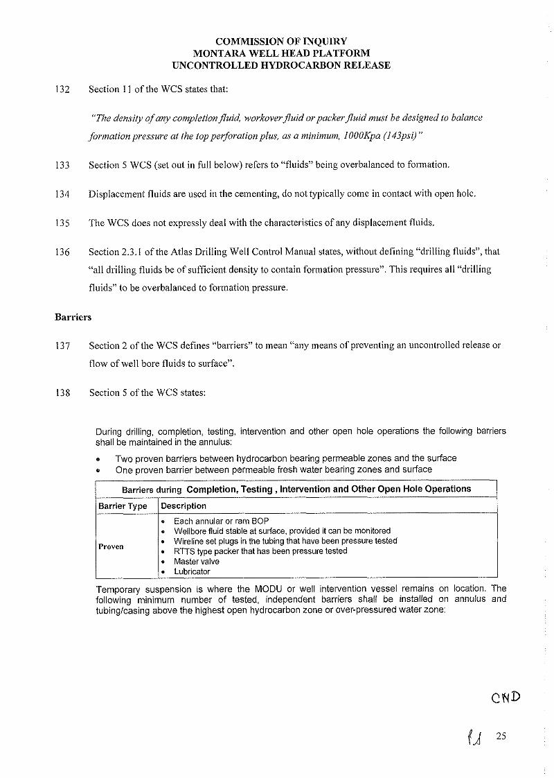
138 Section 5 o f the WCS states:
During drilling, completion, testing, intervention and other open hole operations the following barriers shall be maintained in the annulus:
e Two proven barriers between hydrocarbon bearing permeable zones and the surface One proven barrier between permeable fresh water bearing zones and surface
Barriers during Completion, Testing, Intervention and Other Open Hole Operations
Barrier Type
Proven
Description
e Each annular or ram BOP e Wellbore fluid stable at surface, provided it can be monitored
Wireline set plugs in the tubing that have been pressure tested RTTS type packer that has been pressure tested
* Master valve Lubricator
Temporary suspension is where the MODU or well intervention vessel remains on location. The following minimum number of tested, independent barriers shall be installed on annulus and tubinglcasing above the highest open hydrocarbon zone or over-pressured water zone:
WIT.1000.0001.0087

OF INQUIRY MONTARA WELL HEAD PLATFORM
UNCONTROLLEDHYDROCARBONRELEASE
1 /Heavy Lifting 1 Heavy Weather Move Rig Over Well DrillinglCompletionlTesting or Intervention
Operations Removellnstall
1 Barriers during Temporary Suspension I
BOPlXmas Tree
I Barrier Type l Description I
1 permanent and I tnmnnmrv
Cement Plug Permanent e Permanent Packer with no controlled internal flow path
I 1. Cemented Casina
1 permanent or 7 fnmnnran,
l BOP closed and locked on drill pipe or tubing . Retrievable Packers
2 temporary
A single temporary barrier may be used for temporary suspension, provided that petrophysical logs and other data confirm beyond doubt that no hydrocarbon zones or over-pressured water zones are present in either the wellbore or annuli.
Temporary
For long terms suspension and abandonment requirement refer to Section 14.
. Wireline Plugs . Fluid with a hydrostatic head greater than formation pressure, provided that the liquid level and density can be monitored and maintained. . Closed SSSV that has been tested
Barriers must be verified in-situ as follows:
Barrier Type
Cement Plug Not surface plugs
Cement plug on bridge $up,
139 "Open hole" operations involve drilling beyond some existing casing so that there is some uncased
hole exposed.
Verification
Tagging with sufficient force to confirm the top of good cement Tagging pressure must equal the equivalent of 3500KPa (500 psi) . Or Pressure testing to 7000 KPa (1000PSI) over leak off . Tag bridge plug then pressure testing to 7000 KPa (1000PSI) over leak off after setting cement plug
e Waiting until the sutface cement (tail) samples are set, providing that the cement iob aroceeded normallv and a clear pressure differential was observed prior to
Annulss Cement
All Other Barriers
140 Sections 14.1 and 14.2 o f the WCS relevantly state:
. , bumping the plug
e The differential pressure must confirm that the TOC is a minimum of 50m above any hydrocarbon or over-pressured water zone . B either pressure or inflow testing
14.1 Long Term Suspension
Long Term Suspension is when the MODU leaves the well site. Wells must be suspended so that they can be abandoned with rig less intervention to meet the standards below.
Two permanent tested barriers must be installed in the annulus and well bore above any hydrocarbon zone or over pressured zone. The following are permanent barriers:
0 NO
WIT.1000.0001.0088

OF INQUIRY MONTARA WELL HEAD PLATFORM
UNCONTROLLED HYDROCARBON RELEASE
Barrier Type
Permanent
Description
Pressure tested cement Plug (min 30m in length) Permanent Packer with no controlled internal flow path and cement on top Cemented Casing with proven TOC Hanger Packer Tubing Seals Annular Master Valve
Open hole
Casing
Potentially productive zones behind casino
>30m above the hanger. .
This plug must be tagged or pressure tested to 3500KPa (500psi) above the leak off or estimated fracture gradient at the point of injection.
14.2 Abandonment
Two permanent tested barriers must be installed in the annulus and well bore above any hydrocarbon zone or over pressured zone. Abandonment Programs must comply with the following:
/ S e c t i o n 1 Requirement
Cement plugs shall be placed with a minimum of 30m of cement above and a minimum of 30m below any significant oil, gas or fresh water zones Where there is open hole below the casing shoe a cement plug shall be placed extending a minimum of 30m above and 30m below the casing shoe, or
A cement retainer with effective back pressure control shall be set >10m and <30m above the casing shoe with a cement plug calculated to extend at >30m below and >15m above the retainer. Where lost circulation conditions exist a permanent type bridge plug should be set <45m above the shoe with >15m of cement on top. Intervals of cased hole between cement plugs shall be filled with fluid suitably inhibited to prevent the corrosion of casing string. All must be cemented off.
Casing Stubs inside Casing
Perforations
Liners
A cement plug shall be placed to extend >10m above >40m below the stub. A retainer may be used in setting the required plug.
A cement plug shall be spotted and extend from at least from 30m below to at least 30m above the top perforated interval or
* A cement retainer set in the casing not more than 45m above the top of the perforated interval with a cement plug extending at least 15m above the retainer provided the perforated interval is isolated from open hole below or subject to the above if a succession of retainers are used to isolate a series of perforated intervals. . The top-most retainer requires a minimum of 15m of cement placed above it. This plug must be tagged or pressure tested to a minimum of 3500KPa (500psi) above the leak-off or estimated fracture gradient at the point of injection. . A cement plug shall be placed immediately above each liner hanger to extend
CND
Surface . All casing strings on wells to be abandoned shall be severed below the seabed. . A surface cement plug >45m in length shall be placed in the innermost casing string extending to the seabed with the top of the plug <45m below the seabed. No annular space which extends to the seabed shall be left open to drilled hole below the annular space.
WIT.1000.0001.0089

OF INQUIRY MONTARA WELL HEAD PLATFORM
UNCONTROLLED HYDROCARBON RELEASE
For offshore wells, a seabed survey and subsequent cleanup by ROV shall be conducted and noted in the IADC Drilling Report. A video shall be made and sent to the Drilling Superintendent.
A well abandonment schematic shall be prepared at the wellsite and sent to the Drilling Superintendent for final drafting together with full details of the components. The schematic shall include all relevant dimensions and equipment serial numbers to ensure traceability.
A corrosion cap should be installed on the MLS.
A trash cap should be installed on the conductor or the subsea wellhead.
Neither section 5 nor section 14 of the WCS expressly mention pressure containing corrosion cap but,
instead, refer to 2 different types of functionally similar casing seals. These are RTTS type packers
(section 5) and tubing seals (section 14).
These seals like pressure containing corrosion caps are also manufactured devices machined to
withstand manufacturer's specified amounts of pressure and designed to be inserted into and removed
ftom wells as required.
RTTS packer stands for "Retrievable Test Treat and Squeeze" packer and they work by essentially
squeezing an elastima element against the inside oftlie casing to form a seal.
The tubing seals are 0 rings fitted to a tubing hanger to form a seal within a machined surface in a
well head.
A pressure containing corrosion cap uses 0 rings to form a seal within a machined surface withiu a
MLS hanger.
The tubing lianger has a flow path through the middle whicli must be plugged to form a seal. Typically
the plug is a tubing lianger plug (very similar in design to apressure containing corrosion cap) and
secured into place within the flow path of the tubing lianger.
The RTTS packer and the pressure containing corrosion cap both have meclianical valves that allow
for pressure testing or fluid to be pumped below the barrier and serve to form a seal that can be
removed as required.
The pressure containing corrosion cap is at surface and threaded onto the MLS hanger and the RTTS
packer is designed for use at points deeper into the well. The pressure containing corrosion cap also
protects the threads required for tie back from corrosion that might occur through exposute to tlie
elements.
WIT.1000.0001.0090

OF INQUIRY MONTARA WELL HEAD PLATFORM
UNCONTROLLED HYDROCARBON RELEASE
Each o f a RTTS packer, tubing hanger and pressure containing corrosion cap are designed to allow the
pressure beneath them to be checked and released while they are in place.
Each o f a RTTS packer, tubing hanger and pressure containing corrosion cap are designed so that they
can be installed through a BOP i f that is required.
The WCS lists possible barriers by their functional characteristics. Accordingly references to tubing
hanger and RTTS packer in the WCS are essentially interchangeable and are synonyms for pressure
containing corrosion caps in the context o f a choice as a barrier.
Temporary and long term suspet~sion and abandonment
Section 5 o f the WCS defines temporary suspension by reference to the MODU staying on the well
site and to four anticipated scenarios when drilling work would be temporarily suspended. Section 5
sets out the necessary barriers in each o f those scenarios.
Sections 14.1 and 14.2 oftlie WCS address Long Term Suspension and Abandonment and set out the
barrier requirerncnts in each o f those circumstances.
A Long Term Suspensiorl is "when the MODU leaves the well site". Section 14.1 o f the WCS then
refers to the wells being "suspended so that they can be abandoned with rig less intervention".
When section 5 o f the WCS was prepared it was not intended to describe all eventualities involving a
temporary suspension.
When section 14 o f the WCS was prepared, it was intended to apply to the anticipated situation where:
(a) a sub sea well is suspended at a sea bed wellhead;
(b) the drilling rig leaves the site;
(c) the well in that situation may be left for years waiting for a decision to cornplete the well or it
may be abandoned; and
( d ) the objective in our "long term suspension" part oftlie WCMS was to ensure that a well
suspended for a long period on the seabed was suspended robustly such that a MODU d id not
have to be mobilised to abandon the well. The alternative, i f a robust suspension has been
conducted, is to use a ROV to cut the wellhead at seabed level to abandon the well
permanently.
WIT.1000.0001.0091
OF INQUIRY MONTARA WELL HEAD PLATFORM
UNCONTROLLED HYDROCARBON RELEASE
157 The WCS were not intended to provide a prescriptive set of rules, nor to provide standards for every
scenario that may have been encountered during a well operation. The WCS are a component part of
the WCMS, the focus of which is ongoing risk management that is specific to conditions encountered
in each particular well operation, assessment of those risks and appropriate decisions being made. Part
1.3 of the WCS allows for the WCM to risk asses any deviation in accordance with the Well
Construction Risk Management Process and approve that deviation. This is what occurred in the case
of the H1 Well.
158 The scenarios in section 5 of the WCS are, however, more applicable to the Montara well suspension
scenario than section 14 of the WCS. The Montara well suspension scenario was, in essence, a
temporary suspension. The suspension of HI did not involve any abandonment of the well but the
MODU was leaving the site. The MODU was planned to return after Topsides installation.
159 When the DP was changed and the HI Well was suspended the intention was to always return to the
wells, including the H1 Well, with the MODU. In other words, the wells were not suspended so that
they could be abandoned without the intervention of the MODU. So, while the MODU did leave the
well site the suspension of tlle wells did not m e t the other criteria defining a long term suspension.
H1 Well specifics
Overview of Drilling Programs - originalplan and revisions
160 The original plan for the Moutara field development was to have the WHP Topsides in position and
for the West Atlas to be positioned adjacent to the completed WHP to drill and complete the wells by
batch drilling.
161 This plan was unable to be executed due to issues with the contracted construction vessels which
resulted in the WHP Topsides not being installed as originally planned.
162 This resulted in the DP being revised to incorporate two phases
163 The first phase was to drill and suspend the wells at the 244mm (9%") casing point prior to the WHP
Topsides installation and the second phase was the continuation of drilling and completio~i of the wells
after installation of the WHP Topsides.
164 The DP was initially revised in November 2008 to incorporate the fact that tlle WHP Topsides would
not be in place and the wells sequentially drilled dowr~ to the 244mm (9%") casing shoe and
cw
WIT.1000.0001.0092

OF INQUIRY MONTARA WELL HEAD PLATFORM
UNCONTROLLED HYDROCARBON RELEASE
suspended and then revised in January 2009 to reflect that tlie wells were to be batch drilled down to
tlie 244m1n (9%") casing shoe and suspended.
165 The DP 1B addressed the conipletio~i of the wells after the suspension (incorporating the drilling of the
reservoir section of the horizontal wells and the running of the sand exclusion screens) and was issued
with "As Built" information after the wells had been suspended.
Tltc cemcntirtgplun for tlrc 244rnrn (9*/8'~ cusing
The original design of the H1 Well contemplated a well head at surface. However, it was recognised
that if there was no well head at surface tlie design of the Montara wells in suspension needed review.
A review of the drilling program was conducted and on about 30 January 2009 I received a Well
Construction Change Control Form No D65005A 003 fsom Mr Wilson that addressed an issue that
arose from tbat review.
This identified that we did not have enough PCCCs to cover all the MLSs arid that if neither a PCCC
or well liead was in place, the TOC for the 244mm (g5/?) casing should be extended further than was
originally programmed. This change was to extend the cement up into the 340mm (1 33/g))) casing shoe
so that there was an effective seal within the annulus at tbat point.
This change would reduce risk of release through the 340m1n (13 %") X 244mm (9%") annulus.
Change from cement plug to PCCC - H1 Well
170 When designing tlie Montara well program my preference was to design the program on the basis that
PCCCs would be used as a barrier rather than cement plugs because:
(a) In my experience PCCCs are effective barriers;
(b) I considered that PCCCs were barriers that would comply with sections 2 and 5 of the WCS;
(C) PCCCS protect the threads required to subsequently tie back the casing strings at the end ofthe
MLS fsom cossosion. The WCS says that PCCCs should be used on a MLS;
(d) PCCCs allow pressure below the PCCC to be checked prior to removal, whereas cement plugs
do not;
(e) if cement plugs are used within un-cemented casing, a situation can arise during the drill out of
that plug where right hand torque applied to the cement can result in left hand torque applied &W
WIT.1000.0001.0093

OF INQUIRY MONTARA WELL HEAD PLATFORM
UNCONTROLLED HYDROCARBON RELEASE
to the casing above. This left hand torque can result in the casing backing out and loosing
pressure integrity. Using a PCCC avoids the risk of damaging the 2441nm (9%") casing when
drilling out a cement plug;
(f) if a problem was identified such as pressure below a PCCC then an alternative course of action
could be taken. In the case of the 244m1n (9%") PCCC, trapped pressure below could be
managed by nippling up the BOP on the 340mm (13 %") casing and removing thePCCC in
controlled conditions; and
(g) the original drilling program only contemplated one PCCC cap being available (which would
be used in GI). Nor did it include bringing cement up inside the 3401nm (13 W ) shoe on the
244mm (9%") cement job. Bringing cement up inside the 340mm (13 W ) shoe effectively
provided a closed chamber in the 340mm (13 W ) X 2441nm (9%") annulus and two PCCCs
were considered to be an improvement on the original plan.
However, because PTTEPAA did not originally have enough PCCCs in inventory and available for all
of the wells (namely Montara G1, H1 Well and Montara H4), the DP was designed to set a cement plug
from 160111 to 115111 in the 2441111n (9%") casing of the H1 and H4 wells.
After a suitable 244mm (9%") PCCC became available, a change control to the DP was issued to
remove the planned ce~nent plug in the H1 Well and replace it with PCCC. We made this change
because, for the reasons that I have already explained, this was a safer and more compliant design. It
also replicated the design in the DP for the G1 well. We didn't have enough PCCCs to do it on all the
Montara wells: we had allocated one for the G1 well and ended up with enough to do two, so we
allocated the second of them to the second well, the H1 Well.
The 244mm (9%") PCCC became available shortly before the 244mm (9%") casing on the 1-11 Well
was due to be rut1 and a change was communicated to the Drilling Supervisor by etnail from Chris
Wilson dated 3 March 2009 and was reflected in the forward plans on the West Atlas.
March 2009
174 1 was in Perth between 1 and 12 March 2009.
175 Mr Wilson and I shared the day to day operational responsibility for rig operations.
176 In about early March 2009, the drilling being undertaken in the 1-31 Well reflected the stages set out in
paragraphs 5.23, 5.24 and 5.29 of the DP. These stages were: CNP
WIT.1000.0001.0094

OF INQUIRY MONTARA WELL HEAD PLATFORM
UNCONTROLLED HYDROCARBON RELEASE
5.23 Run 244mm (9 518") Casing - Montara H1
196) Hold JSA and rig-up TESCO Casing Running tool (dressed to run 244mm (9 518") casing) to the TDS.
197) Run 244mm (9 518") casing per casing tally (Appendix 3)
e PDC Drillable float and shoe with sharkbite installed above the float.
After making-up the shoe track (with baker-loc) fill with mud to check for flow through.
. Fill each joint of casing with mud whilst running in the hole
e Monitor the trip tank closely firstly due to hydrocarbon zone being open (Montara Formation) and secondly for surge effects on the lower Johnson and Puffin inducing losses.
Record up and down weights every 5 joints and compare against the torque and drag modeling.
198) Make-up the 244mm (9 518") MLS joint
199) Run in the hole with the casing on the 244mm (9 518") landing string
200) Wash down the last joint of casing and land out the casing on the MLS
. Space out so that the cement head is at the rig floor level.
201) Circulate 110% of the casing volume
202) Install WO pup joint - Vam Top pin X Buttress box
Required to install the surface cement head onto the 244mm (9 518") casing
203) Retract the blocks to move the Tesco casing running tool out of the way (do not rig the casing running tool down as it will be required to back out the casing from the MLS)
204) Make up the cement head.
o Take slow circulation rate (5OSPM)
e Retract the blocks and lay out the Tesco Casing Running Tool offline.
205) Cement casing per program (Appendix 4)
r Monitor for returns
. Displace cement with inhibited seawater
Ensure cement head is flushed while displacing the cement
. Estimate TOC using differential pressure prior to bumping the plug and report same on the DDR
Pressure test the casing to 27.5MPa (4000psi) for 10 minutes if plug bumps
CND
WIT.1000.0001.0095

OF INQUIRY MONTARA WELL HEAD PLATFORM
UNCONTROLLED HYDROCARBON RELEASE
Offline: Install the BOP cranes to the BOP's in preparation for nippling down the BOP's.
206) Check that the floats are holding
207) Disconnect the cement head and remove XI0 joint of casing
5.24 Secure Well - Montara H1
208) Whilst waiting on cement use the Tesco Casing Running Tool, back-out the 244mm (9 518") MLS running tool from the MLS by rotating the casing to the right for 8-9 turns.
e The anticipated torque to back-out the running tool is 2034 - 4745 Nm (1500 - 3500 ft-lbs)
209) Once the running tool is released recover the landing string to surface and lay out same
210) Rig down the Tesco casing running tool
21 1) Run in the hole with drillpipe to 210m
212) Spot 3.97m3 (25bbls) of hi-vis
213) Pull out of the hole to 160m
214) Set cement plug from 160m to 115m
215) Pull out of the hole to 115m
216) Circulate hole clean with inhibited seawatel
217) Pull out of the hole
218) Wait on cement (both casing cement and also the cement plug)
5.29 Reduce the pressure in the Diverter Overshot Packer and lift the BOP's clear of the surface wellhead. Suspend Well - Montara H1
267) Skid to Slot 13-WD-003
268) Make-up a 340mm (13 3/8") casing spear and run in the hole.
269) Engage the 340mm (13 318") casing and apply right-hand rotation to release the MLS running tool from the hanger.
e The anticipated torque to back-out the running tool is 2034 - 4745 Nm (1500 - 3500 ft-lbs)
270) Recover the casing to surface on the spear and lay out the casing and rack back the spear.
271) Run in the hole with the 508mm (20) Lynx running tool and make-up same to the landing joint,
272) Rotate the 508mm (20") casing to the left to release the landing joint (joint torqued to less than all other joints).
273) Pull out of the hole with the 508mm (20") casing. CND
WIT.1000.0001.0096

OF INQUIRY MONTARA WELL HEAD PLATFORM
UNCONTROLLED HYDROCARBON RELEASE
274) Lay out the landing joint and rack back the Lynx running tool
275) Offline - Apply "lubriplate" lubricant to the threads on the 340mm and 508mm (13 318" and 20") MLS' prior to installing the corrosion cap
276) Offline - Make-up 508mm (20") corrosion cap and run in the hole with same on a tugger
Figure 20 shows the suspended status of Montara H1
177 It was planned to install the 2441nm (9%") PCCC on Saturday, 7 March 2009. To avoid any potential
delays or inconvenience in getting approval for that change on a Saturday, a verbal request of the
change was made to the Designated Authority on the afternoon of Friday, 6 March 2009 to make sure
that there was aural approval in place to install the PCCC before the work commenced.
178 MS Wilson sent an email to the DA on 6 March 2009 that included a suspension diagram which showed
the presence of a 244mm (9'1;) PCCC. This was to alter the Stage 1 suspension, which only allowed
for the installation of the 244m1n (95/8") PCCC as the 340nnn (13~1;) casing, wellhead and BOP's
would remain in place until the BOP was removed to be installed onto anotlier well being drilled on
the WI-IP.
179 Suspension Diagram - Stage 1 was as follows:
WIT.1000.0001.0097

OF INQUIRY YlONTAl<A WELL HKAD 1'1.A'l'l;OR.M
IJSCOKTROLLEL) HYDROCAIWON RELEASIK
AC!L7 MmLm HI ST.1
Suspension Diagram -Stage 1
The Designated Authority gave the verbal approval on 6 March 2009.
On 7 March 2009 1 read the DDR dated 6 March 2009. 1 was aware from that repost that on 6 March
2009 the 244mm (9'18") casing was run into the H1 Well without reported problems until someti~ne
between 18:OO hrs and 21:OO hrs when circulation was required. A ball had been pre-installed in the
casing string so that if the pumps were engaged, the float valves would convert fson1 auto f i l l to
conventional valves. The 6 March 2009 DDR recorded:
WIT.1000.0001.0098

OF INQUIRY MONTARA WELL HEAD PLATFORM
UNCONTROLLEDHYDROCARBONRELEASE
" ... continued to RIIf casing washing down each jointfioni 2620111 to 3208ni with 1.2n?/nlin at
2.48MPa. Average running speed = 12 jointdhr. Note: Once washing down was comn?enced the self
,filli~ig shoe andfloat lost the selffilling function."
182 I was also aware from DDR dated 6 March 2009 that the float valves were functio~ial at that time on 6
March 2009.
183 Mr Wilson was on duty on the weekend of Saturday, 7 and Sunday, 8 March 2009.
184 By convention, on weekends Mr Wilson and I would only speak about work issues if we thought that
there was a problem to solve or an opportunity to improve something. I do not recall speaking to Mr
Wilson on either Saturday, 7 or Sunday, 8 March 2009.
185 The 2441nm (95/8") casing on HI Well was cemented on 7Marcli 2009.
186 On the morning of Sunday 8 March 2009 1 saw:
(1) the email updatc dated 8 March 2009 from the PTTEPAA personnel on West Atlas to, amongst
other people, Mr Wilson and tnc that contained a description of events of 7 March 2009, which
included three lines of bullet points that read:
e Tested casing to 27.6MPa - OK, bled off and encounteredfloat,failure
e WOC 3 hrs, concurrently changed oil on TDS and cleanedflow lines.
e Checked cement integvity - OK. ND cement head and laid out same.
and attached the:
(a) PTTEPAA Daily Drilling Report dated 7 March 2009; and
(b) Advantage Drilling Mud Report dated 7 March 2009; and
(2) the morning update email from Mr Wilson to various people iucluding me, Donald Millar
(Atlas Drilling - Perth), Silnon Johnson (Atlas Drilling - Singapore) and the West Atlas and
which included the comment that:
"checkedfloats on casing - OK".
187 The reports attached to the email update dated 8 March 2009 (ie the DDR and the Mud Report) in
conjunction with Mr Wilson's email were the only reports given to me on 8 March 2009.
ciu
WIT.1000.0001.0099

OF INQUlRY MONTARA WELL HEAD PLATFORM
UNCONTROLLEDHYDROCARBONRELEASE
The official report for drilling operations is nor~nally considered to be the Atlas Drilling ]ADC report.
The IADC reports are prepared by the driller and signed by the drillers, the OIM a~id tlie drilling
supervisor.
However, Atlas Drilling IADC report # 6695576 dated 7 March 2009 was not available to me on 7 or 8
Marcli 2009. The report is a large format document and 1 only received it sometime after 8 March
2009 which was tlic normal procedure.
I was not given a copy of the Halliburton Cementer's report dated 8 March 2009 until after 21 August
2009.
Mr Wilson's email indicated to me tliat the well integrity was satisfactory.
To me, the critical comment about the status of tlie cementing of tlie slioe casing as at 7 March 2009 is
the bullet poiut in the email update dated 8 March 2009 from the PTTEPAA on WestAtlas that
"Checked cement integrity - O r .
1 read this to mean that a positive step had been taken to check tlie integrity of the slioe casing cement
and that the shoe was a competent barrier.
That was consistent with what I understood Mr Wilson's emailed coinme~it "checkedjloats on casing -
OK" to mean.
The drilling comments section in the Advantage Drilling Fluids Report-7 dated 7 March 2009,
mentions "WOC [Wait on Cement] Retestedjloat ... ".
Whilst I did not give this as much weight as the comments in the emails, it also confirmed to me tliat a
test had been performed to check that the cement in the shoe casing formed a competcnl barrier.
"Wait on cement" is a shorthand reference to a delay while the drilling team waited for tlie cement to
cure.
The PTTEPAA Daily Drilling Report dated 7 March 2009 mentions:
(a) at 1400 - 1500: "Switched back to Hafliburton andpressure tested casing to 27 6Mpa x 10
n7ins - OK Bled ofltest pressure to 1.37Mpa then observedpressure rapidly increase to
8.9Mpa. Note: pumped 1.47 m3 and bled off2.62 m3, suspectedjloat valve failure. Pumped
2.54 m3 back into casing at 9.3MPa."
(b) at 1500 - 1800: "Waitedon cernent .... ; and CND
WIT.1000.0001.0100

OF INQUIRY MONTARA WELL HEAD PLATFORM
UNCONTROLLEDHYDROCARBONRELEASE
(c) at 1800 - 1830: "Open casing annulus to atmosphere and confirm no backflow ".
199 It was apparent from the reports that were available to me that the float valves failed in service.
However, in the light of the other comlnents in the reports and eniails I did not suspect that the valve
failure indicated anything that might have adversely affected the integrity ofthe cement in the shoe
casing.
200 Putting together the connnents made in the emails and the DDR and Advantage Mud report that were
attached to the email from the I'TTEPAA personnel on West Atlas that I saw on the morning of 8
March 2009, I considered that the cementing had been completed properly, that the cement in the shoe
casing was a competent barrier and the well integrity was not a concern.
201 The DDR dated 7 March 2009 indicates that the installation of the 2441n1n (9%") pressure containing
corrosion cap began on 7 March 2009 at 2200hrs.
202 On 12 March 2009 I signed a Well Construction Change Control Form No D65005A to formalise the
verbal approval for the change to the 2441nm (9%") PCCC and the removal the cement plug in the H1
Well.
203 The process of aural notification (on 6 March 2009) followed by written confirmation of the change
(on 12 March 2009) was in keeping with our management of change process.
204 Also on 12 March 2009 an approval was requested to suspend the M1 Well based on Suspension
Diagram - Stage 2 including 244mm @/p) and 340mm ( 1 3 ~ 1 ~ ) PCCCs. Suspension Diagram - Stage
2 was as follows:
CND
WIT.1000.0001.0101
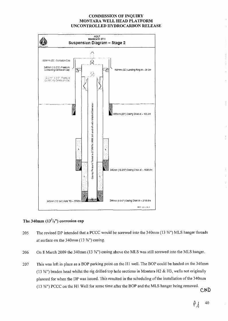
OF INQUIRY MONTARA WELL HEAD PLATFORM
UNCONTROLLED HYDROCARBON RELEASE
AWL7 hmhrsH1 ST-1
Suspension Diagram - Stage 2
The 340mm (13~18") C O ~ T O S ~ O I I cap
205 The revised D1' intended that a PCCC would be screwed into the 340mm (13 X") MLS hanger threads
at surface on the 34001111 (13 %")casing.
206 On 8 March 2009 the 3401n1n (13 W ) casing above the MLS was still screwed into the MLS hanger.
207 This was lefi in place as a BOP parking point on the HI well. The BOP could be landed on the 3401nni
(13 X") braden head whilst the rig drilled top hole sections in Montara H2 & H3, wells not originally
planned for when the DP was issued. This resulted in the scheduling ofthe installation of the 3401nm
(13 %") PCCC on the H1 Well for some time after the BOP and the MLS hanger being removed. CND
WIT.1000.0001.0102

OF INQUIRY MONTARA WELL HEAD PLATFORM
UNCONTROLLED HYDROCARBON RELEASE
Tlie installation of a 3401nm (13 %") PCCC on the HI Well is noted in tlie comments section of the
DDR-14 from Mo~itara H2 dated 16 April 2009 and reporting on the activities for 16 April 2009.
That DDR says (on page 3): "Corrosion capsfitted to 340nim MLS and trash caps$tted to 508nim
conductors on H1 and H3-ST1".
Tlie Montara H2 DDR-14 dated 16 April 2009 arrived on shore on 17 April 2009.
On 17 April 2009 1 received an elnail from PTTEPAA staff on tlie West Atlas saying the PCCCs were
installed. The e-mail was the morning update email that contains tlie morning reports that is sent in
by 0700hrs each day. Under the section "Co~nments/Activities" the third bullet point is "Corrosion
caps and trash caps installed by on wells H1 and H3-ST-l".
A Trash Cap sits on tlie top of the 508mm casing and is a non pressure containing cover to prevent
debris entering the well.
Mr Wilson therefore prepared the Suspension As-Built (drawing) showing tlie well suspended with the
340mm (13 W ) PCCC in place.
On 21 April 2009 Mr Wilson and I received by ernail the DDR from Montara H2 dated 20 April 2009
tliat stated in tlie operations section between 0600 and 0700 lirs "Note: Now all 5 wells secured and
protected".
Based on those DDRs I thouglit tliat the 2441nin (9%") PCCC and the 340mm (13 W ) PCCC had been
installed on tlie H1 Well as set out in the DP (as revised by change control).
Suspensioe status of the H1 Well aud the plan for the completion of the wells
216 As at 21 April 2009 and based on the documents that 1 had received, I thought tliat the followitig
barriers were in place (and compliant with the WCS) and would remain in place during the suspension
of the H1 Well and prior to the conmencement of work to prepare the well for the next stageof
drilling:
(a) a cemented shoe;
(b) displacement fluids within the 2441nm (9%") casing (which provided hydrostatic pressure
greater than the pole pressure);
(c) 244nnn (9%") pressure containing corrosion cap;
(d) cement within tlie 3401nm (13 G") X 2441n1n (9%") casing annulus; and
WIT.1000.0001.0103

OF INQUIRY MONTARA WELL HEAD PLATFORM
UNCONTROLLED HYDROCARBON RELEASE
(e) 340mm (13 %") pressure containing corrosion cap.
I also thought based on the documents that I had received that a 508m1n (20") Trash Cap was in place
on the H1 Well.
At that time it was planned that the West Atlas would return to the H1 Well to start the completion
works during JulyIAugust 2009.
The West Atlas returned to the Montara WHP on 19 August 2009.
After initial preparations for work, the initial work scope was to re-establish the top 20 meters of the
casing and MLS back to where the well head was going to be. This involves a tie back of casing
strings.
Next, the BOPs were to be nippled up again and pressure tested. Then the drilling assembly was to go
in and the shoe track and plug drilled out, followed by the horizontal section and then to carry on with
our program as contained in DP 1B.
During the tie back we had to tie back 3 casing strings. Firstly we had to tie back the conductor. The
conductor was strong enough to support the weight of all the loads including the BOPs which were
about 90 tons. With the conductor installed we would cut that accurately to height and then install the
first wellhead section. The first wellhead section elevation would dictate the stack up height for all the
other items. The 340tnm (13~18))) casing would have been tied back and its annular sealed off and then
the 244m1n ( 9'18))) casing tied back and sealed off and at that point we would have nippled up to BOPs
and sta~ted pressure testing.
The plan was to take off the trash cap, nipple up the 508mm (20") conductor with a PCCC on the
340mm (13"/s" casing and a PCCC on the 244nnn (95/s") on that well.
Within the drilling program, DP lB, section 5.6 on page 29 covers the removal of the trash cap,
installation of the conductor and installation of the braden head or initial wellhead section.
The planned steps to tie-back the 5081nm (20") casing on the 131 Well were set out in paragraph 5.6.
The planned steps to remove the 3401nm(13 %") PCCC and tie back the 340mm (13 W ) casing on the
H1 Well were set out in paragraph 5.16 ofthe DP 1B and the planned steps to remove the 244mm
(9%") PCCC and tie back the 244mm (9%") casing on the H1 Well were set out in paragraph 5.17 of
the DP.
CND
WIT.1000.0001.0104

OF INQUIRY MONTARA WELL HEAD PLATFORM
UNCONTROLLED HYDROCAItBON RELEASE
5.6 Tie-back 508mm (20") casing- Montara H1 ST-1
15) Remove the trash cap from the well using a tugger
e Check the threads on the 508mm (20") conductor
16) Rig-up to ru11508mm (20") conductor
17) Make-up the landing string (Figure 28) and run in the hole
18) Carefully make-up the Leopard connection on the MLS and engage the antkotation tabs
19) Rough cut the casing above the mezzanine deck and recover the landing string.
20) Skid to well slot 13-WD-009 (Montara G1)
21) Offline cut the 508mm (20") casing at 4.661m above the platform main deck (Figure 28) with a cold cutter and recover the cut-off.
22) Offlil~e install the Braden Head and orient per Appendix 5 (Due North or parallel to the aft of the rig pointing starboard). Record wellhead serial liumber on the DDR
23) Offline install Aker debris cover PIN 5857764'5
5.16 Tie-back 340mm (13 318") casing- Montara H1 ST-1
173) Run in the hole with the corrosion cap running tool.
174) Make up the TDS before engaging the running tool onto the corrosion cap (this will allow for any pressure below the corrosion cap to be observed on the standpipe and then bled-off through the choke manifold)
175) Engage the corrosion cap and check for any pressure below the corrosion cap. Note any pressure on the IADC and the DDR. Bleed-off any pressure via the choke manifold.
176) Remove the corrosion cap by rotating clockwise for 8-9 turns with a torque of 2034 - 4745Nm (1500-3500 ftlbs) and recover same to surface.
177) Rig-up to run 340m1n (13 318") casing
178) Make-up the MLS tieback tool to the landing string.
. Confirm all seals are intact
. Lubricate seals with Jet Lube AP-5 or equivalent. DO NOT use pipe dope or lubricant containing metal particles.
179) Run in the hole with the MLS tieback tool and space-out to ensure that no casing couplings are in the vicinity of the surface wellhead
180) Lower the tieback tool onto the MLS and apply 0.9 to 2.2MT weight down and mark the pipe at the rotary table
181) Rotate the string to the right 9.5 to 10.5 turns maintaining constant weight down on the string with a torque of 3390 to 5424Nm (2500 - 4000 ftlbs). The string should have moved 89mm down. CNB
WIT.1000.0001.0105

OF INQUIRY MONTARA WELL HEAD PLATFORM
UNCONTROLLED HYDROCARBON RELEASE
182) Hydrotest the tieback by filling the casing with water.
183) Install the casing slips (Aker PIN W85859-133EA-2W). The slips are fully installed when the distance from the top of the slips to the top of the starter head is 2161nm (8.52")
184) Install the cold cutter and cut the 340mm (13 318") casing 127mm (5") [+/- 3mm (0.12")] above the top surface of the starter head ensuring the outer edge has a bevel per Aker Procedures 61- PH2059-70 (M1 76).
185) Once the casing is cut recover the landing string to surface.
186) Change from casing elevators to drillpipe elevators and make-up the pack-off running tool complete with the pack-off (PIN W85860-133A-24).
187) Whilst rigging-up to run the pack-off clean out the cavity above the slips in the starter head in preparation to run the pack-off.
188) lnstall the pack-off per Aker Procedures 61-PH2059-70 (M176).
189) Pressure test the pack-off to l0.9MPa (1584 psi) - 70% of the collapse pressure of the casing for 10 minutes
190) Once successfully pressure tested engage the pack-off
191) Recover the pack-off running tool
192) Change out the 340mm (13 318") pack-off running tool for the 244nim (9 518") pack-off running tool.
5.17 Tie-back 244mm (9 518") casing-Montara H1 ST-I
193) Run in the hole with the co~rosion cap running tool.
194) Make up the TDS before engaging the running Loo1 onto the corrosion cap (this will allow for any pressure below the corrosion cap to be observed on the standpipe and then bled-off through the choke manifold)
195) Engage the corrosion cap and check for any pressure below the corrosion cap. Note any pressure on the lADC and the DDR. Bleed-off any pressure via the choke manifold.
196) Remove the corrosion cap by rotating clockwise for 8-9 turns with a torque of 2034 - 4745Nln (1500-3500 ftlbs) and recover same to surface.
197) Rig-up to run 244mm (9 518") casing
198) Make-up the MLS tieback tool to the landing string.
. Confirm all seals are intact
Lubricate seals with Jet Lube AP-5 or equivalent. DO NOT use pipe dope or lubricant containing metal particles.
199) Run in the hole with the MLS tieback tool and space-out to ensure that no casing couplings are in the vicinity of thesurface wellhead
lnstall a 340mm X 244mm (13 318" X 9 518") casing centralizer below the surface wellhead as the 244mm casing will be cut without the casing slips in place. CND
WIT.1000.0001.0106

OF INQUIRY MONTARA WELL HEAD PLATFORM
UNCONTROLLEDHYDROCARBONRELEASE
200) Lower the tieback tool onto the MLS and apply 0.9 to 2.2MT weight down and mark the pipe at the rotary table
201) Rotate the string to the right 9.5 to 10.5 turns maintaining constant weight down on the string with a torque of 3390 to 5424Nm (2500 - 4000 ftlbs). The string should have moved 891nm down.
202) Hydrotest the tieback by filling the casing with water.
203) Install a water head bushing on the casing complete with a side entry sub and a TIW.
204) Pressure test the casing to 27.5MPa (4000psi) for 20 minutes to check the integrity of the MLS connection.
NOTE: This will pressure test tlie entire 244m1n (9 518") casing string
205) Nipple-down from the casing pressure test
206) Install the cold cutter and cut the 244mm (9 518") casing 509mm (20.04") [-+l- 3mm (0.12")] above the top surface of the starter head ensuring the outer edge has a bevel per Aker Procedures 61-PH2059-70 (M176).
207) Recover the landing string
208) Change from casing elevators to drillpipe elevators (whilst installing the wellhead)
209) Install the unitized Aker Wellhead per the Aker procedure 61-PH2059-70 (M176). Orient the wellhead per the wellhead orientation procedure (Appcndix 5)
210) Pressure test the neck seals against the 3401nm (13 318") casing to 10.9MPa (1584 psi) - 70% of the collapse pressure of the casing for 10 minutes.
21 1) Pressure test the cavity between the starter liead and the unitized wellhead to 10.9MPa (1584 psi) - 70% of the collapse pressure of the casing for 5 minutes.
212) Install tlie 244m1n (9 518") slip landing guide (Figure 30)
r The slip landing guide will consist of a cut-off joint of 2441nm (9 518") casing with 3 guides welded to the inside base. The guide will be lowered through the unitized wellhead and mate-up with the already cut 244mm (9 518") casing. The slip landing guide will allow the slips to be wrapped around the casing and lowered into the wellhead without snagging- up on the already cut casing.
213) Install the casing slips (Aker PIN W85716-095A-3W). The slips are fully installed when the distance from the top of the slips to the top of the unitized wellhead is 703mm(27.66")
214) Once the slips are installed remove the slip landing guide.
215) Make-up the pack-off running tool to drillpipe (a minimum of 3T weight is needed to set the pack-off)
216) Install the pack-off per Aker Procedures 61-PH2059-70 (M176).
217) Pressure test the pack-off to 22.96MPa (3330 psi) [70% of the collapse rating of the casing] for I0 minutes
218) Once successfully pressure tested engage the pack-off C'ND
WIT.1000.0001.0107

OF INQUIRY MONTARA WELL HEAD PLATFORM
UNCONTROLLEDHYDROCARBONRELEASE
219) Take 4.5T overpull to confirm that the pack-off is engaged
220) Recover the pack-off sunning tool
221) Skid to slot 13-WD-001 (Montara H4)
222) OFFLINE: Install the tree Jig (Figure 3 1) to allow construction to take measurements for the flow lines. Once measurements have been taken nipple down the jig
223) OFFLINE: Remove one manual 52mm (2 1116") side outlet valve and replace with two hydraulic actuated 52mm (2 1/16") side outlet valves for the 244rnm (9 5/8") a~lnulus gas injection manifold tie in. Confirm with Production/Construction crew on correct side of unitized wellhead for the Gas injection manifold tie in as well as hydraulic actuator orientation for hydraulic control line tie in.
224) OFFLINE: Install the 4.5m high pressure riser using a double drive lock adaptor to the unitized wellhead (Figure 32).
225) OFFLINE: Install the drive-lock adaptor (loose) and cross-over spool onto the riser in preparation for the BOP's. When the rig is tying back the last well (H3) the BOP's should be able to skidded towards the H1 well and madeup to the drive-lock assembly
Paragraph 5.17 of the DP 1B shows that the 244m1n (9%") casing would be exposed to atmosphere
when the 2441nm (9%") PCCC was removed.
As the Dt' planned a batch drilling program the 244mm (9%") casing would be exposed to atmosphere
while the 244nnn (9%") casing was tied back on other wells.. 'Illis could take 24 hours or so.
This exposure to atmosphere is consistent with convention on surface wellhead type operations where
allowances are made for BOP removal after cement has set as contemplated in the Atlas Drilling Well
Control Manual and commonly practised within the industry.
20 August 2009
I arrived on West Atlas that morning at around 0830 hrs. The purpose of my visit was to review the
setup for operations at the WHP, catch up with the drilling supervisors and rig crew. I was on board
Wesf Atlas to conduct a pre start-up management visit arriving on 20 August and expecting to dcpart
21 August.
When I arrived on the West Atlas my understanding of the suspension status of the 1-11 Well was that
nothing had altered since April 2009.
The trash cap was removed as per step 15 in DP 1B but 1 was not present when that occurred.
Once the trash cap was removed it was apparent that the 3401nm (13 ?h") PCCC was not installed and
that some surface corrosion of the threads had occurred. CND
WIT.1000.0001.0108

OF INQUIRY MONTARA WELL HEAD PLATFORM
UNCONTROLLED HYDROCARBON RELEASE
l did not know about the missing 3401nm (13 W ) PCCC until after my arrival on West Atlas on the
morning of 20 August 2009.
When we were notified that the H1 Well did not liave a PCCC on 20 August 2009, it was a surprise to
me.
The absence of the 3401nm (13 W ) PCCC raised 2 issues. First, why was there no 3401n1n (13 W )
PCCC in place? Secondly, what needed to be done going forwards?
1 was in tlie PTTEP office on West Atlas when a pl~one call was placed to Mr Wilson advising him that
there was no 340m1n (13 %'3 PCCC on the H1 Well. I discussed by telephone with Mr Wilson that we
would need to find out what happened regarding tlie tiiissing 340mm (13 W ) PCCC. Tlie events of the
morning of 21 August altered my priorities.
Mr Wilson and I discussed what we considered the best course of action to be and we agreed that we
would need to determine why the PCCC had not been installed and follow up with Mr Millal. later.
The concern about the missing 3401n1n (13 W ) PCCC was earmarked for later review. The well had at
that time been suspended for 5% months and there was no evidence of anything to be concerned about
fiorn an imminent well safety perspective. Also some of tlie personnel who should have been involved
in installing the 340m1n (13 %") PCCC were onshore, meaning that enquiries with them would be
delayed.
My priority was to deal with tlie cussent situation.
It was reported to me that there was evidence of some scale or corrosiou on the tie back threads on tlic
340mm (13 %") MLS hanger. This corrosion was likely to liave been caused because the 3401n1n (13
W ) PCCC had not protected the threads.
Tlie MLS tieback tool has two sealing mechanisms. One is a metal to metal sealing face and the other
in an 0 ring seal. Both of these sealing mechanistns are important to the integrity of the seal for the tie
back.
Unless the corrosion on the tie back threads on the 3401nm (13 W ) MLS hanger was removed the
subsequent casing integrity on tie back was at risk.
I knew that unless the 244m1n (9%") PCCC was removed there was insufficient access to clean tlie
corroded threads properly
WIT.1000.0001.0109
OF INQUIRY MONTARA WELL HEAD PLATFORM
UNCONTROLLED HYDROCARBON RELEASE
244 An additional benefit of removing the 244mm(9%") PCCC at that time was the ability to inspect the
effectiveness of the corrosion removal. This ability would be lost if the 5081nm (20") conductor was
installed at that stage as planned.
245 A plan was devised to alter the planned well tie back sequence in order to clean the 340mm (13 W ) tie
back threads to address this issue.
246 My thinking was that this action was the right thing to do because:
(a) It would give us the best chance of making good the 340mm(13 W ) casing tie back threads and
seal surfaces;
(b) It was a rescheduling of planned operations, because the 244m1n PCCC was planned to be
removed within a day of the removal of the trash cap; and
(c) the 2441n1n (9%") casing was also planned to be exposed to atmosphere for some time after the
244mm (9%") PCCC was removed and that might be for 24 hours before any additional barrier
was in place,
and was made in the context of the information that was conveyed to me showing that the shoe casing
was a competent barier, the H1 Well cement displacement fluid was overbalanced to the reservoir and
if there had been any change in the fluid status since cement placement on 7 Mxch 2009, this would
be evident and managed by checking for trapped pressure below the 2441n1n (9%") PCCC before its
removal.
247 1 expecled Mr Wilso~i to discuss the chaege in sequence with the West Atlas rig manager Mr Millar but
did not do so myself.
248 1 discussed the cleaning of the 3401nm (13 %") threads with Paul O'Shea (Drilling Supervisor) and left
it to him to communicate the proposed change of tasks to the OIM and gain his agreement.
249 1 was not present when the 244m1n (9%") PCCC was removed but this occurred around mid day on
20 August 2009.
250 Removing a PCCC aftcr it has been in place for some time is an operation that can be undertaken
under controlled conditions. The corrosion cap running and retrieving tool has 0-rings on the inside
diameter of the tool to seal on the neck of the PCCC. It also has a shaft facing downwards to push the
poppet valve off seat. When the poppet valve is pushed off seat, any trapped pressure will be released
into the drill string. From within the drill string excess fluid pressure can be measured and bled off. c w
WIT.1000.0001.0110
OF INQUIRY MONTARA WELL HEAD PLATFORM
UNCONTROLLED HYDROCARBON RELEASE
Document TM-CR-MON-150-00003 dated 6 July 2009 being tlie Montara Phase lB Drilling &
Completion Program (DP 1B) covers removal of the PCCC. Whilst no pressure is expected,
precautions are always taken to ensure tliat tlie task is managed with minimal risk to personnel. Had
there been any trapped pressure evident, 1 am confident that the persons on the rig would have stopped
the job to re evaluate the options.
Based on the well status of the NI Well, tlie planned exposure to atmospliere whilst tlie tie backs were
undertaken and the absence of any physical evidence of a change in fluid status, there was no
compelling reason to re-install the 244m1n (9%") corrosion cap.
Approximately 15 hours passed on 20 and 21 August 2009 without a PCCC on the 244m1n (9%")
casing of tlie H1 Well. Under the DP a period of time was required to install tlie tie back casing, during
which the 2441n1n (9%") casing was planned to be exposed to atmosphere.
A gas detector was used as was appropriate prior to PCCC removal. Some small bubbles were
detected. The gas detected did not register any hydrocarbons.
21 August 2009
On tlie morning of 21 August, I awoke and dressed into my coveralls before going to the PTTEP office
on West Atlas. This was at about 05 15lirs.
I was taking stock of what was happening when at about 0538hrs, the general alann sounded.
I went to my muster station and heard a PA announce~ne~it stating that the alarm was not a drill.
Shortly afterwards, one of the drilling supervisors, Brian Robinson came up to the lifeboat station
wearing liis lifejacket. I asked Iiim what had happened and lie stated tliat "the well has unloaded". I
asked him wliicli one and he said 1-11, He said that lie thought it was coming from the well annulus as
the flow was coming up the 5081nm (20") conductor and seemed to be falling in on itself.
I think that there was a PA announcement askiug me to go to the radio room but I may be mistaken. In
any event I went to tlie radio room as that was where our personnel were going to be and where tlie
OIM was.
As tlie reports started to come through I realised that we had at tlie very least, areportable release, ie
one in which 80 litres of hydrocarbons is discharged into the marine environment. I did not know the
extent of the release at that time but it was reasonable to assume that it exceeded 80 litres. CMD
WIT.1000.0001.0111
OF INQUIRY MONTARA WELL HEAD PLATFORM
UNCONTROLLEDHYDROCARBONRELEASE
I asked our drilling eugineer 1 logistics person to get a camera and start getting some photographs of
the release for analysis.
1 went down to the WHP with Brian Robinson and a Atlas Drilling assistant driller to see the well area.
We reported in to the radio room via telephone as we boarded the WHP as per procedures. The well
was not flowing. We could hear bubbling from the top of the conductor. We could not see down into
the couductor as there were misty vapours restricting view. A check with the gas detector indicated
high couceotrations of hydrocarbons. We tidied up a few loose objects and returned to West Atlas.
My thought process as to cause at that time was that the well had probably started to flow from the
shoe track, because:
(a) an annulus flow was possible however given that the 340nnn (13 W ) PCCC had not been
installed and that annulus had been unprotected for 5% months, and no flow the day before I
thought that the coincidence required for a strong flow that morning was vely unlikely.
(b) I could envisage a small worm hole through cement in the shoe track allowing an influx into
the well. However, with no flow the day before demonstrating an overbalance condition in the
well, that too was unlikely; and
(c) of the two main possibilities, option (b) above was clearly the most likely but the reason f o ~
the well starting to flow was unknown.
I thought that if (b) above was in fact the case, we had to get a plug in the well quickly whilst we still
had substantial hydrostatic pressure in the well.
I reported back to the drilling supervisor and the 01M with my aualysis of the situation. It was decided
to try to niove the rig back across to H1 Well and install a RTTS packer in the 2441n1n (9%") casing.
This would take some time to get in place.
A phone call was made to Mr Wilson in Perth by the drilling supervisor, Paul O'Shea to let him know
what was going on.
Preparations to shift the rig over the top of the H1 Well were underway
1 went down with the tool pusher or the OIM to address the crew who were still mustered io the galley.
We outlined what we knew and what we were going to tsy to do to rectify the situation. The OIM
advised everyone to stay awake for a while in case the situation got worse. CND
WIT.1000.0001.0112

OF INQUIRY MONTARA WELL HEAD PLATFOKM
UNCONTROLLED HYDROCARBON RELEASE
I then took some notes and went to check how large tlie slick looked
At about 0723 hrs, the well started to flow again. The flow was significant and it looked like there was
a substantial oil component being discharged.
I was on the main deck and found the drill crew hurrying back towards their muster stations. One guy
offered to go up the derrick to help but the toolpusher (I think) and I told him no and to head directly
to muster stations.
In my lifejacket and other personal protective equipment, I went back to the control room. We looked
at the situation and it was getting a little worse.
Now the OIM is in charge of the rig and all POB including myself fall under his cotnniand in an
emergency. That said, there was a good working relationship between the OIM and the drilling
supervisors and a similarly good working relationsliip between the drilling supervisors aid myself. 1
also had a good working relationship with Donald Millar, the rig manager.
The OIM decided to evacuate non essential personnel and the drilling supervisors and 1 concurred with
that decision.
At one point tlie OIM was talking to Donald Millar on the telephone advising ofthe situation. I was
called over to tlie phone to give Mr Millar my analysis of the situation. It was brief and not
encouraging.
A cloud of gas and oil vapour started to drift across the deck of tlie rig on the pot* aft quarter. The
OIM ordered the main engines shut down. This was prudent as the port aft quarter is where tlie engine
exhausts are located and despite spark arrestors, keeping the engines running increased the risk of a
fire.
With tlie main engines shut down the rig went onto the emergency generator. I think that we lost the
telephone circuits at that time which was disappointing.
I recall enquiring if the rig could still skid tlie cantilever with the main engines shut down. Tlie answer
was no.
Our status at that time was:
(a) the well was blowing out;
CWD (b) we had no BOP's installed;
WIT.1000.0001.0113

OF INQUIRY MONTARA WELL HEAD PLATFORM
UNCONTROLLED HYDROCARBON RELEASE
(c) we were not located over the top of the well;
(d) with main engines down we could not skid over the top of the well;
(e) if the source of the blow out was what I suspected, we were cased all the way to reservoir so
there was little chance of the well bridging and stopping the flow of its own accord;
( f ) I was concerned that if the flow was through a relatively small pathway in residual cement in
the shoe track that erosion would only enlarge the pathway. That meant that the blow out was
more likely to get worse than better; and
(g) we still had about 20 POB
We discussed the situation and I stated my opinion that given our status, full abandonment of the rig
was the best course of action. There was no prize for staying on board if we subsequently lost people.
The OIM and drilling supervisors agreed and the OIM ordered evacuation of the rig.
I mentioned to Paul O'Shea to bring our mobile satellite telephone. We had one available mainly for
use in cyclone season. Paul brought that phone with him to Life boat # 3.
Once we were strapped in and the final muster taken, we abandoned the rig in lifeboat # 3. This left
one boat intact on the rig, Lifeboat # 4.
Lifeboat #3 stalled on the decent but whatever difficulty that existed with the lifeboat was quickly
fixed and the decent continued without further incident.
Once i n the water and away from the rig we made our way to Lady Audrey, a supply boat on standby
in the area.
Paul O'Shea made a call to Mr Wilson from the lifeboat to let him know that all POB were safely
evacuated from West Atlas.
From that point, we went into action responding to the incident.
Specific questions raised by the Commission
Possible explanation of the cementing issues arising on 7 March 2009
287 1 have been asked by the Commissioner to provide my views aboutthe cementing and pressure testing
carried out on the H1 Well, in particular in relation to the apparent failure of the Float Shoe andlor C NI)
WIT.1000.0001.0114

OF INQUIRY MONTARA WELL HEAD PLATFORM
UNCONTROLLED HYDROCARBON RELEASE
Float Collar non-return valves for the 244mm (9%") casing of tlie H1 Well andlor the backflow of
hydrocarbons andlor other substances following the release ('bleeding off ) of pressure after the
'bumping of plugs' in the 244mm(9%") casing of the H1 Well.
I have already set out my knowledge about the situation as at 7 and 8 March 2009. That is, I
considered from the materials that were provided to me at that time that despite the in service failure
ofthe valves, the cementing of the 2441nm (9 518") shoe casing had been correctly completed
Nevertheless, to address the Commissioner's question, 1 have reviewed the forward plans, Advantage
drilling reports and IADC report and in particular the following documents:
(a) PTTEPAA Daily Drilling Report of 7 March 2009;
(b) PTTEPAA H1 STI 244x11111 (9%") Cementing Report of G March 2009;
(c) West Atlas IADC report of 7 March 2009;
(d) Halliburton cement report Mootara H1 ST1 9.625in Production Csg FARPACK 8 Mar 0 9 . ~ 1 ~ ;
(e) Atlas Drilling Well Control Manual; and
(f) West Atlas 1 SDI Operations Procedures Manual
Based on my interpretation of those materials, I have drawn some co~iclusions about what might have
occurred in relation to the cementing of the H1 Well 2441nm (9%") casing on 7 Marcli 2009, which I
set out below.
Installing 244mm (9%") casing into H1 Well - 6 & 7 March 2009
291 The casing was run acceptably, however, there were a few problems listed in the DDR dated 7 March
2009:
(a) some tight hole was encountered at 372Gm MD. This is not unusual and can usually be
circulated past.
(b) tlie handle on a pin securing the Flush Mounted Spider (FMS) failed and the FMS had to be
removed by stripping it over the top of the casing when set in tlie rotary slips; and
(c) the Casing Drive System (CDS) jaliitned on the casing and removal required laying out some
casing and replacing the stuck components. CND
WIT.1000.0001.0115

O F INQUIRY MONTARA WELL HEAD PLATFORM
UNCONTROLLEDHYDROCARBONRELEASE
292 Despite this the casing was landed on depth and the casing circulated I 10% of its volume as required.
Cement Calculatio~is
I consider that, liaving reviewed all of the relevant calculations and with the benefit of hindsight that
the celnent calculations were incorrect.
The concept of taking top of tail cement above top reservoir was both in tlie DP (2923.5m on the
planned directional profile was 30m TVD above top reservoir) and iucreased in change control
D65005A 001 to a depth of 69m TVD above top reservoir.
A draft celnerlt design from Halliburton, our cementing contractor to Mr Wilson on 28 January 2009
included the revised top of cement in the calculations. It also included the original casing measured
depth of 3,373111 as per program because at that time the well had not been drilled to total depth and
the final bottom depth remained unknown.
Unfortunately, it appears that the calculations performed in the field referenced not the top of cenient
as intended in the DP and subsequently revised in the change control D65005A 001 but the difference
between programmed top of cement and programmed shoe depth. This apparent error resulted in a
calculated tail slurly length of 550m instead of a tail slurry length of 1052.5111 as would have been
calculated if the top of cement reference had been honoured and the bottom varied to suit the as drilled
shoe deptk parameter, This apparent error was duplicated by all the personnel who calculated the
cement volumes.
The 3 1 lnnn hole section was drilled to a depth of 37961~1 for geological reasons not 3,373m as
programtned.
The consequence of this apparent error was that insufficient tail cement slurry was pumped to bring
the top of the tail slurry above tlie top of the reservoir as intended in the DP and revision to DP.
However, this apparent error did not have an impact on the well control incident that subsequently
occurred.
This apparent error was not identified until after 21 August 2009 and upon review of the situation in
tlie light of the uncontrolled release and in an attempt to determine what might have caused the release.
WIT.1000.0001.0116

OF INQUIRY MONTARA WELL HEAD PLATFORM
UNCONTROLLEDHYDROCARBONRELEASE
Pressure Testing Casing
During the displacement of the cement on 7 March 2009, the pressures seemed to be close to expected
That is to say, there was a pressure increase as the cement was displaced from the casing and tlie pre
bump pressure indicated that a substantial cement volume was located above the shoe track.
The DDR reports a pre bump circulating pressure of 7.9 - 10.0 MPa. ( 1145 - 1450 psi ) and that the
bump was confirmed wit11 13.7 MPa ( 1987 psi ). This is in line with expectations.
Pressure testing of the casing was then transferred to the Halliburton cementing unit. The initial
pressure at the cement unit was a little under 5.5 MPa (800 psi) as read from the graph in Halliburton
cement report Montara H1 STI 9.625in Production Csg FARPACK 8 Mar 0 9 . ~ 1 ~ .
304 The handover pressure was somewhat less than the pressure recorded on the drill floor using the mud
pumps. I assume that some fluid was bled off whilst lines wwe changed over.
305 With the cement unit pumping to pressure test the casing, tlie pressures and volumes pumped were
consistent with good sealing plugs aud nonnal casing expansion. The pressure was taken to 13.8 MPa
(2000 psi) and held for a few minutes. A steady pressure with no pumping was consistent competent CND
WIT.1000.0001.0117

OF INQUIRY MONTARA WELL HEAD PLATFORM
UNCONTROLLEDHYDROCARBONRELEASE
casing and cement displacement plugs sealing properly. After a few minutes at the lower pressure, the
the pumps were then used to bring the pressure test up to 27.6 MPa (4000 psi) as per program.
Forward plan # l 7 dated 6 March 2009 revision 1 covers the running and cementing of the 244mm
casing on the H1 Well. The casing test is described using the duration from the DP which is 10
minutes.
The duration of the pressure test was as per the DP but insufficient for the WCS. This was an error in
the DP that was not picked up during the review process.
Points 14 to 20 include the setting of a celnent plug in the upper part of the casing as originally
required in the DP.
In the WCS at section 9.2 it states:
9.2 Casing Pressure Testing
All surface and intermediate casing strings shall be pressure tested to the design burst pressure but not exceeding 70% of the minimum internal yield pressure, and not less than 5600 kPa (800 psi).
The pressure shall be held for a minimum of 20 minutes, except that for casing sizes 2 340mm (13.318") and strings with length <500m.
The reference to pressure testing for 10 minutes in the DP was incorrect. The 20 minutes referenced
in the WCS at sectiou 9.2 should have applied. (Note that the 10 minute figure was the minimum value
prescribed in the Schedule of Specific Requirements direction under the Petvoleum (Submerged
Lands) Acl, now no longer in force).
To form an opinion about whether the prcssure test duration was a contributing factor in the
subsequent uncontrolled release, I have considered the data obtaiued during the pressure testing. Based
on that review I consider that pressure testiug for 10 minutes rather than 20 minutes was not a
contributing factor in the subscquent uncontrolled release.
Extrapolating from the data recording the well pressure througl~out the testing there was likely to have
been a continuing iucrease in the pressure for the 10 minutes after the testing period (which is
consistent with the heat of the chemical reaction in the cementing process) and demonstrating casing
integrity and no apparent leak.
Upon cotnpletion of the pressure test, displacement fluid was bled off to the cement unit's measuring
tanks.
c m
WIT.1000.0001.0118

OF INQUIRY MONTARA WELL HEAD PLATFORM
UNCONTROLLEDHYDROCARBONRELEASE
During the bleed down process the pressure reached about 0.82 MPa (120 psi), when there was a
sudden change and the pressure started to increase. This increase was interpreted as a float valve
failure and the fluid was shut in at the cement unit. The shut in pressure stabilized at about 8.3 MPa
(1200 psi) .
My interpretation of the suddeu pressure increase is that the float valves were working correctly but
failed in service with between 6.9 MPa and 7.6 MPa pressure differential across the valve. It should be
noted that the valve is rated for at least 20.7 MPa pressure differential according to the manufacturer's
specifications.
111 terms of volumes pumped and returned by the cement unit, the initial shut in pressure when the
cement uuit was engaged was about 5.17 MPa. There would have been some fluid co~npressioo 1
casing expansion to hold that pressure. The cementing job log reports that after waiting on cement, the
shut i n pressure was released for a 3.5bbl return. From that 1 would estimate that we probably had
about 4bbls of trapped pressure at the initial cement unit pressure of 750psi.
During the casing test, a further 9.25bbls of fluid was added to the casing to increase the casing test
pressure to 27.6 MPa.
When pressure was released at the cement unit after the casiug test but before the float valves failed, I
would have expected 13 - 14 bbls of fluid to have been returned. It is uot unusual to get a little more
fluid retumed that? pumped because the fluid expands as it heats up.
The volume of fluid returned to the cement unit before shut in after the float failed was recorded at
16.5bbls in the cementer's job log.
I understand that once the personnel on the cement w i t realized that the pressure was increasing
instead of decreasing as expected they shut in the well at the cement unit. The additioual 2 - 3 bbls of
fluid returned once the float valve failed is reasonable and to me indicates good reactions to an
unplanned event.
I would also expect that for the shut in pressure to increase from about 0.83 MPa to about 8.3 MPa,
without pumping from surface would only be achieved by an additional influx from the casing shoe in
the order of 3bbls.
Up until the point where the float valves failed, the top plug and bottom plug should have remained on
seat in the landed position. The Top plug and possibly the Bottom plug would tend to work as a
floating piston within the casing and move up the casing once there was a fluid influx from below. CND
WIT.1000.0001.0119
O F INQUIRY MONTARA WELL HEAD PLATFORM
UNCONTROLLED HYDROCARBON RELEASE
Using the above interpretations of the reported flows, the top cement plug may have been displaced up
the casing by about 6 bbls.
The cementers records then show that fluid was then pumped back into the casing at a steady pressure
of around 9.0 MPa to a volume of 16.5bbls.
There was no further pressure bump and tlie pump back was stopped at 16.5bbls.
When pumping fluid back into the well one would expect to see a pressure increase when the top plug
reseated at the float collar. This pressure increase was not seen. This suggests that either there was
plug bypass or that something other than the float valves had failed. There could have been a casing
failure however that is unlikely. It is most likely that the plugs failed to seal when they reached the
float collar.
This could indicate that by pumping fluid back into the well without pressuring up on the casing once
the top plug should reasonably have seated, cement might have been displaced from the shoe track.
Pumping 16.5bbls of fluid could mean that about 9 - 10 bbls of fluid was pumped into tlie shoe track.
If that did occur, it would be a volume that exceeds the shoe track volume making it likely that the
cement in the shoe track was displaced out of the shoe.
After pumping the 16.5bbls of fluid back into the well, the system was shut in and the cement allowed
to set.
Waiting 011 Cement
329 After waiting on cement, the casing pressure was released and 3.5bbls of fluid returned at the cement
unit.
330 The well was flow checked and there was no flow.
33 1 Apart from an inflow test, no further pressure testing of tlie casiug was attempted. If the above analysis
of the cementing sequence is correct, it is likely that an attempt to pressure test the casing after the
cement had set would have failed.
Testing Shoe Cement Iutegrity
332 In the drilling comments section of the Advantage Drilling Fluids Report-7- of 7"' March 2009 it is
stated, "WOC (Wait on Cenzent) Reiestedfloat. . "This note is also made in the IADC report filled in
by the driller. CWG'
WIT.1000.0001.0120
OF INQUIRY MONTARA WELL HEAD PLATFORM
UNCONTROLLED HYDROCARBON RELEASE
Having now reviewed other documents, it appears that the reference to retesting of tlie "float" is a
reference to the IADC report filled in by the driller, but the test that was actually performed was an
inflow test that demonstrated no flow.
To be effective, an inflow test requires a differential pressure from the well bore to the casing. This
condition only exists whilst the cement slurry is liquid and therefore providing hydrostatic pressure. If
the cement is set it generates no hydrostatic pressure and the inflow pressure is reduced to reservoir
pressure. As tlie pressure due to the cement displacement fluid exceeded the reservoir pressure there
was no differential pressure to generate any flow from the well.
As the floats had broken in service it did not test the floats at all.
In the Advantage Drilling Fluids Report 7 dated 7 March 2009, drilliug comments section, there is
mention of "WOC (Wait on Cement) Retestedfloat ... "The retesting of the float is no doubt a
reference to the IADC report filled in by the driller. The test that was performed was in fact an inflow
test that demonstrated no flow. It did not test the floats at all.
IADC report # 6695576 dated 7"' March 2009 is a Atlas Drilling West Atlas report covering activities
on West Atlas for that day. The entry of 1800 - 18:30 in this report states "Retest Float Good. RID
CMT head and CMT lines."
The PTTEPAA Daily Drilling Report of 7"' March 2009 mentions:
(a) at 1400: "Switched back to Halliburton andpressure tested casing to 27.6MPax IOniins - Ok
Bled o f test pressure to 1.37Mpa then observedpressure rapidly increase to 8.96MPa.
Note: Pumped 1.47m3 and bled off2.62m', suspectedfloat valve failure. Pun~ped 2.54nf2
back into casing a f 9.3Mpa."; and
(b) at 1800: "Open casing annulus to atmosphere and confirm no backflow ".
The reference to the casing annulus is a discrepancy. Whilst it is possible that the annulus was closed
in using the BOP whilst waiting on cement, it is more likely that the report should llave read "Open
casing to atnzosphere andconfirm no backflow". If the report had been modified thus it would llave
been consistent with other reports.
The Halliburton Cementers report of 8"' March 2009 notes "17:51 BLEED OFF CSG STRING
3.5BBLS BACK, OPSI".
WIT.1000.0001.0121

OF INQUIRY MONTARA WELL HEAD PLATFORM
UNCONTROLLEDHYDROCARBONRELEASE
Tlie Halliburton Cementers report of 8"' March 2009 is tlie most detailed and descriptive of the reports.
Although it does not identify the problem, it does set out what had occurred.
The cetnenters report records tlie final pressure prior to bleed off. It was only 687psi where as at shut
in earlier in the day the pressure was 1300 psi. The difference in pressures in what was supposed to be
a closed system was an indicator tliat something was not quite right.
The driller has interpreted this as a retest of the float and written it down as such. Tlie DDR Ins been
reported as the annulus was opened to at~nospliere and the Halliburton cementer's note "1 7:51 BLEED
OFF CSG S T M 3.5BBLSBACK OPSI" records tliat the pressure trapped in tlie casing was released
to atmosphere and that there was no backflow.
Based on reading each of those reports and trying to reconcile them, what I believe probably happened
is that tlie pressure trapped in tlie casing was released to atmosphere and that there was no backflow.
In other words, an inflow test was conducted and there was no pressure test done.
The Section 8.1 of the Atlas Drilling Well Control Manual has a section titled Waiting On Cement -
Surface Stacks which does not require a pressure test of tlie casing after waiting on cement.
The West Atlas / SDI Operations Procedures Manual section 1.1.3 1 covers cementing intermediate
casing and contemplates a failure of tlie float valves at step 15 of the procedure. This procedure does
not require a pressure test ofthe casing after a suitable period of waiting on cement.
Section 5 of tlie WCS relating to barriers states that "All other barriers Inay be pressure tested or
inflow tested".
Tlie three managing documents referencing casing cementing were complied wit11 because an inflow
test was done on the casing after the period waiting on cement. However, after considering the position
since the uncontrolled release, I think that that was an inadequate response to the cilcumstances of 7
March 2009.
An appropriate action would have been to pressure test the casing to a pressure at least equal to the
expected formation fracture pressure plus a margin. Such a test would properly demonstrate cement
integrity if fluids were bypassing the displacement plugs.
The need for this appropriate action was not recognised by trained and qualified personnel offshore
and communications to both the Atlas Drilling and PTTEPAA office based personnel, including me,
did not trigger a request for further confirmation of cement integrity.
WIT.1000.0001.0122

OF INQUIRY MONTAIU WELL HEAD PLATFORM
UNCONTROLLED HYDROCARBON RELEASE
Pressure testing PCCCs - permanent and tested barrier
The PCCCs have a poppet valve that holds pressure from below. The running and retrieval tool has an
internal shaft that holds the poppet off seat w11ilst the running tool is engaged. This allows for a
pressure test during installation and a check for trapped pressure prior to removal. 1 expected the
Drilling Supervisors to apply a test on the PCCC during installation to verify that no 0 rings had been
damaged during the installation process however testing was not included in the DP, which required
installation to the manufacturer's procedures. The manufacturer's procedures were included in the
docu~nentation sent to the West Atlas. I did not know at the time of the installation of the PCCCs but
have since discovered that the manufacturer's procedures do not require a pressure test after
installation.
The PCCCs did not meet PTTEPAA's criteria for a permanent barrier because they were not pressure
tested. The PCCCs manufacturer's (Vetco) instructions for the PCCCs did not require any pressure
testing of the PCCC in situ.
Had we pressure tested the PCCCs on installation then they would have complied with the necessary
criteria for a permanent barrier for the purposes of the long term suspension despite it not being
included as a specific example in section 14.1.
The revision to forward plan #l7 dated 7"' March 2009 version 2 takes the program revision into
account. It details installation of the PCCC (even though that is only documented as a change control
on 12 March 2009). 11 does not describe a pressure test of the PCCC on i~istallation.
Tlic absence of pressure testing for the PCCCs on installation was not causative of the uncontrolled
release. The PCCCs did not fail under pressure or in any way at all. The PCCC design allowed the
pressure underneath the PCCC to be tested before the PCCC was removed. The testiug was carried out
and the result was that there was no pressure, which was consistent with the HI Well being
overbalanced.
Absence of a 340mm (13 W') PCCC
356 I have set out above, based on the DDRs I thought that the 340mm (13 W ) PCCC had been installed
011 the H1 Well as set out in the DP (as revised by change control).
357 Even after enquiry since 21 August 20009, I do not know why the 3401nm (13 %") PCCC was not
installed on HI.
WIT.1000.0001.0123

O F INQUIRY MONTARA WELL HEAD PLATFORM
UNCONTROLLEDHYDROCARBONRELEASE
The absence of the 340mm (13 %") PCCC should have been known when the 508mm (20") trash cap
was installed. That fact should have been reported through the usual reporting channels and ultimately
I should have been told of the matter (for PTTEPAA) and Donald Millar (on behalf of Atlas Drilling)
should also have been told of the situation.
The cause of the release remains unknown and I do not think that the uncontrolled release was caused
by the absence of the 340nnn (13 W ) PCCC or the absence of any report about the missing 3401nm
(13 W) PCCC.
Re-installing the 244mm (9%") PCCC
I consider that the decision not to re-install the 2441nm (9%") PCCC on 20 August 2009 is justified in
the circumstances that existed at that time.
While it can be argued that with the benefit of hindsight the 2441nm (9%") PCCC should have been re-
installed, all of the signs from the HI Well on 20 August 2009 established that the H1 well was stable
and secure.
The H1 Well was cased and cemented and at the time there was no concern as to the quality of the
cement barriers in the well.
The displacement fluid was overbalanced to formation.
The 1-11 Well had been static since March 2009 and it could reasonably be expected that any
imperfections in the well status would be evident through the presence of pressure or hydrocarbons
immediately below the 2441nm (9%") PCCC.
There was no pressure or oil or gas detected when the 244mm (9%") PCCC had been removed in the
first place and the West Atlas was scheduled to return to the HI Well within a short time, the DP 1B
contemplated the 244mm (9%") PCCC being removed and remaining off the MLS casing for a
significant period.
The cause of the release remains unknown and I do not think that the leaving the 2441nni(9%") PCCC
off the MLS casing after it had been removed as programmed in the DP IB caused the uncontrolled
release.
Communication issues
367 1 consider that the communications between PTTEPAA staff onshore and offshore were very good.
CND
WIT.1000.0001.0124

OF INQUIRY MONTARA WELL HEAD PLATFORM
UNCONTROLLED HYDROCARBON RELEASE
I also consider that the connnunications o f PTTEPAA staff onshore and offshore and the Atlas
Drilling staff and the personnel o f other contractors was also very good.
Those communications were frequent, regular and open. PTTEPAA, Atlas Drilling and each
contractor had independent and co-ordinated lines o f communication.
The facts about the cementing o f the shoe float were contained in distributed reports to well qualified
people (including me) but it appears that the circumstances d id not call on anyone to analyse that
information.
It is possible that one or more people could have identified problems in the well construction operation
but none o f those problems were by themselves the cause o f the uncontrolled release and the absence
o f identification o f problems was more consistent with honest mistake rather than poor
communication.
Nevertheless the HI Well behaved as it was expected based on the co~nmunications o f the relevant
personnel. The reason why the H 1 well became underbalanced has not been identified. I do not believe
that any communication issues caused the uncontrolled release.
1 understand that a person who intentionally makes a false statement in a statutory declaration is guilty o f an
offence under section 1 1 o f the Statutory Declarations Act 1959 (Cth), and I believe that the statements in this
declaration are true in every particular.
Declared at Pert11 the 8th day o f March 2010
declaration is made
'ha PL ! F-7(c_(. (.0,1( d a ~ , bJ{-( e p I R ~ L&A L ,P j.pcf(-cc0 NLR Full name, qualificatio~i and address o f person before whom the declarat~on 1s made
WIT.1000.0001.0125