Embed Size (px)
Citation preview
7/11/2019 Bit Dull Grade
http://slidepdf.com/reader/full/bit-dull-grade 1/99
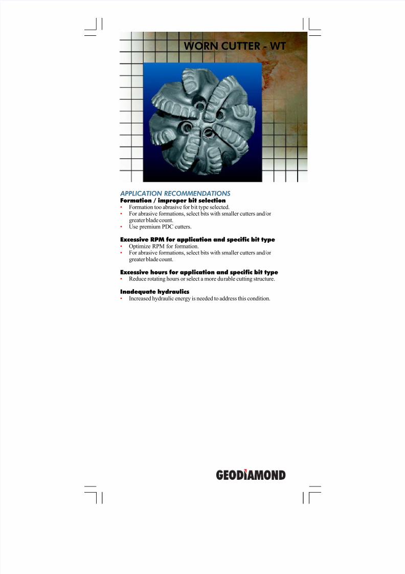
APPLICATION RECOMMENDATIONS
Formation / improper bit selection• Formation too abrasive for bit type selected.• For abrasive formations, select bits with smaller cutters and/or
greater blade count.• Use premium PDC cutters.
Excessive RPM for application and specific bit type• Optimize RPM for formation.• For abrasive formations, select bits with smaller cutters and/or
greater blade count.
Excessive hours for application and specific bit type• Reduce rotating hours or select a more durable cutting structure.
Inadequate hydraulics• Increased hydraulic energy is needed to address this condition.
WORN CUTTER - WT

7/11/2019 Bit Dull Grade
http://slidepdf.com/reader/full/bit-dull-grade 2/99
GeoDiamond Dull Grading Manual
WT - Worn Cutter Worn cutter is a condition that describes the reduction in the cutter height due to the drilling action. This is a normal and expected wear mode. Worn cutters on a PDC is described by a value 0 to 8, 0 being nowear and 8 being no cutter remaining.
POTENTIAL CAUSES
Formation / improper bit selection• Formation too hard / abrasive for bit selected.
Excessive RPM for application and specific bit type• Excessive RPM accelerates the mechanism of wear due to increases
in relative surface velocities.
Excessive hours for application and specific bit type
• Wear due to rotating hours greater than typical expectations.
Inadequate hydraulics• Inadequate cuttings removal, accelerating cutting structure wear.
7/11/2019 Bit Dull Grade
http://slidepdf.com/reader/full/bit-dull-grade 3/99
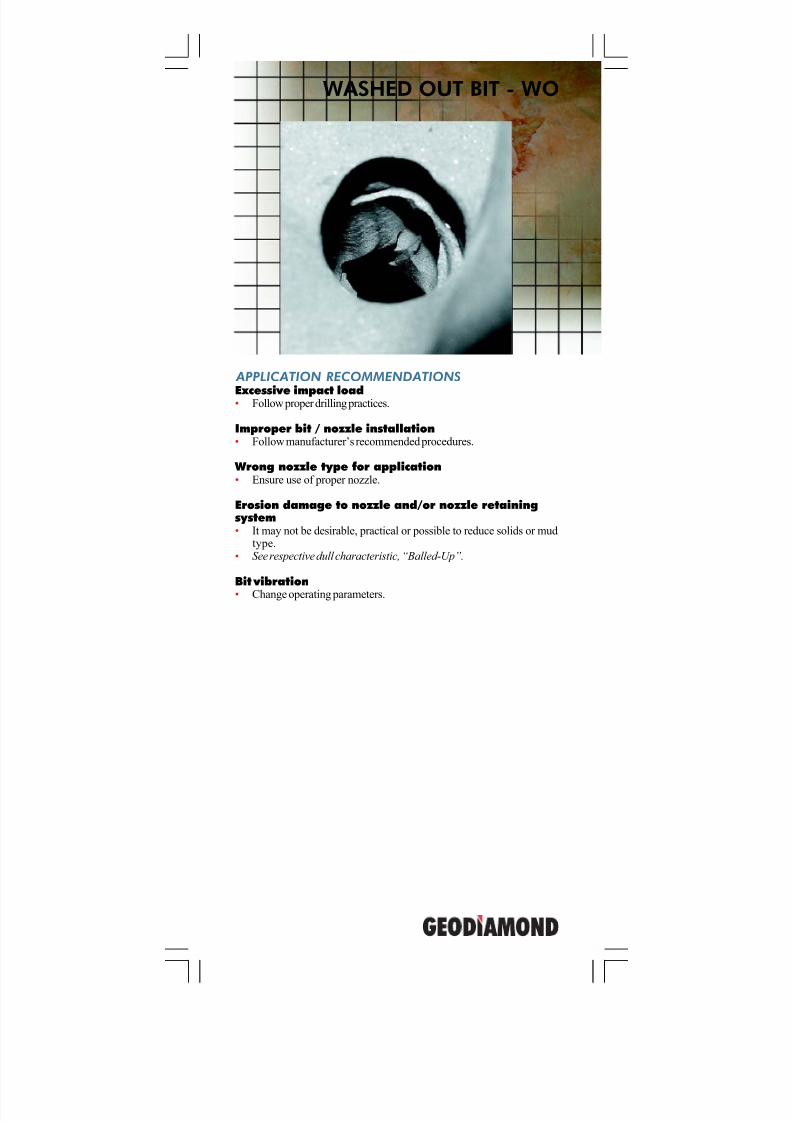
WASHED OUT BIT - WO
APPLICATION RECOMMENDATIONS
Excessive impact load• Follow proper drilling practices.
Improper bit / nozzle installation• Follow manufacturer’s recommended procedures.
Wrong nozzle type for application• Ensure use of proper nozzle.
Erosion damage to nozzle and/or nozzle retainingsystem• It may not be desirable, practical or possible to reduce solids or mud
type.• See respective dull characteristic, “Balled-Up”.
Bit vibration• Change operating parameters.
7/11/2019 Bit Dull Grade
http://slidepdf.com/reader/full/bit-dull-grade 4/99
GeoDiamond Dull Grading Manual
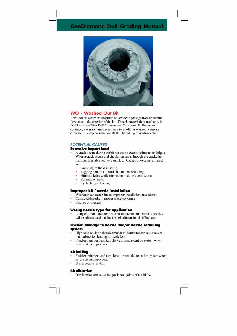
WO - Washed Out BitA washout is where drilling fluid has eroded a passage from an internalflow area to the exterior of the bit. This characteristic is used only inthe “Remarks Other Dull Characteristic” column. If allowed tocontinue, a washout may result in a twist off. A washout causes adecrease in pump pressure and ROP. Bit balling may also occur.
POTENTIAL CAUSES
Excessive impact load• A crack occurs during the bit run due to excessive impact or fatigue.
When a crack occurs and circulation starts through the crack, thewashout is established very quickly. Causes of excessive impactare:• Dropping of the drill string.• Tagging bottom too hard / intentional spudding.
• Hitting a ledge while tripping or making a connection.• Running on junk.• Cyclic fatigue loading.
Improper bit / nozzle installation• Washouts can occur due to improper installation procedures.• Damaged threads, improper make-up torque• Pinched o-ring seal.
Wrong nozzle type for application• Using one manufacturer’s bit and another manufacturer’s nozzles
will result in a washout due to slight dimensional differences.
Erosion damage to nozzle and/or nozzle retainingsystem• High solid muds or abrasive muds (ex. hematite) can cause severe
internal erosion leading to nozzle loss.• Fluid entrainment and turbulence around retention system when
severe bit balling occurs.
Bit balling• Fluid entrainment and turbulence around the retention system when
severe bit balling occurs.• See respective section.
Bit vibration• Bit vibration can cause fatigue in tool joints of the BHA.

7/11/2019 Bit Dull Grade
http://slidepdf.com/reader/full/bit-dull-grade 5/99
RING OUT - RO
APPLICATION RECOMMENDATIONS
Improper bottom hole pattern break-in• Proper bottom hole pattern break-in is considered to be when a new bit achieves uniform cutting structure loading. This is done withlight weights and slow rpm and is normally achieved with in 6 to 12inches. At that point WOB and RPM can be gradually increasedto typical operating levels.
Formation / improper bit selection• Consider more abrasion resistant cutters.• Consider more abrasion resistant cutting structure.• Consider more impact resistant cutting structure.
Excessive WOB for application and specific bit type• Optimize WOB for formation.• Consider using a shock sub or thruster.• For hard formations, then select a bit with more blades and/or
smaller cutters.
Excessive hours for application and specific bit type• Select more durable bit type or reduce operating hours.• Broken and/or worn cutting elements can be reduced by decreasing
operating hours or by selecting a more robust cutting structure.
Bit vibration• Change operating parameters.
Improper drilling practices• Refer to Recommend Drilling and Drillout Procedures.
7/11/2019 Bit Dull Grade
http://slidepdf.com/reader/full/bit-dull-grade 6/99
GeoDiamond Dull Grading Manual
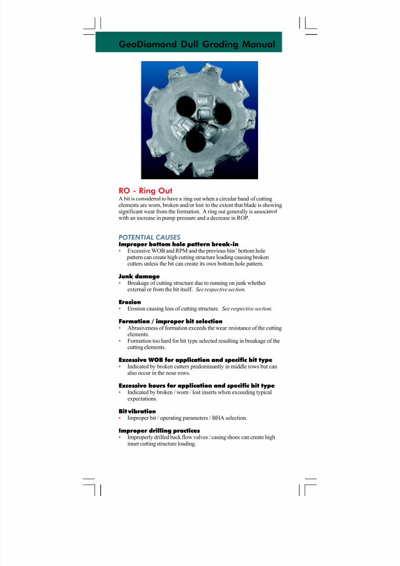
RO - Ring OutA bit is considered to have a ring out when a circular band of cuttingelements are worn, broken and/or lost to the extent that blade is showingsignificant wear from the formation. A ring out generally is associatedwith an increase in pump pressure and a decrease in ROP.
POTENTIAL CAUSES
Improper bottom hole pattern break-in• Excessive WOB and RPM and the previous bits’ bottom hole
pattern can create high cutting structure loading causing brokencutters unless the bit can create its own bottom hole pattern.
Junk damage• Breakage of cutting structure due to running on junk whether
external or from the bit itself. See respective section.
Erosion• Erosion causing loss of cutting structure. See respective section.
Formation / improper bit selection• Abrasiveness of formation exceeds the wear resistance of the cutting
elements.• Formation too hard for bit type selected resulting in breakage of the
cutting elements.
Excessive WOB for application and specific bit type• Indicated by broken cutters predominantly in middle rows but can
also occur in the nose rows.
Excessive hours for application and specific bit type• Indicated by broken / worn / lost inserts when exceeding typical
expectations.
Bit vibration• Improper bit / operating parameters / BHA selection.
Improper drilling practices• Improperly drilled back flow valves / casing shoes can create high
inner cutting structure loading.
7/11/2019 Bit Dull Grade
http://slidepdf.com/reader/full/bit-dull-grade 7/99
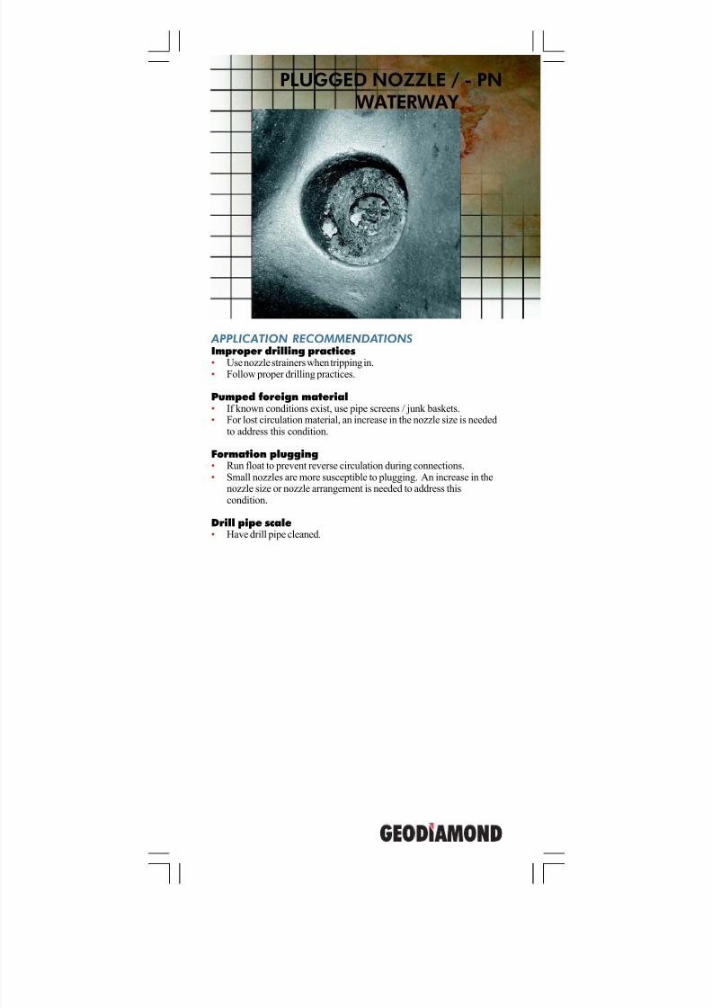
APPLICATION RECOMMENDATIONS
Improper drilling practices• Use nozzle strainers when tripping in.• Follow proper drilling practices.
Pumped foreign material• If known conditions exist, use pipe screens / junk baskets.• For lost circulation material, an increase in the nozzle size is needed
to address this condition.
Formation plugging• Run float to prevent reverse circulation during connections.• Small nozzles are more susceptible to plugging. An increase in the
nozzle size or nozzle arrangement is needed to address thiscondition.
Drill pipe scale• Have drill pipe cleaned.
PLUGGED NOZZLE / - PNWATERWAY
7/11/2019 Bit Dull Grade
http://slidepdf.com/reader/full/bit-dull-grade 8/99
GeoDiamond Dull Grading Manual
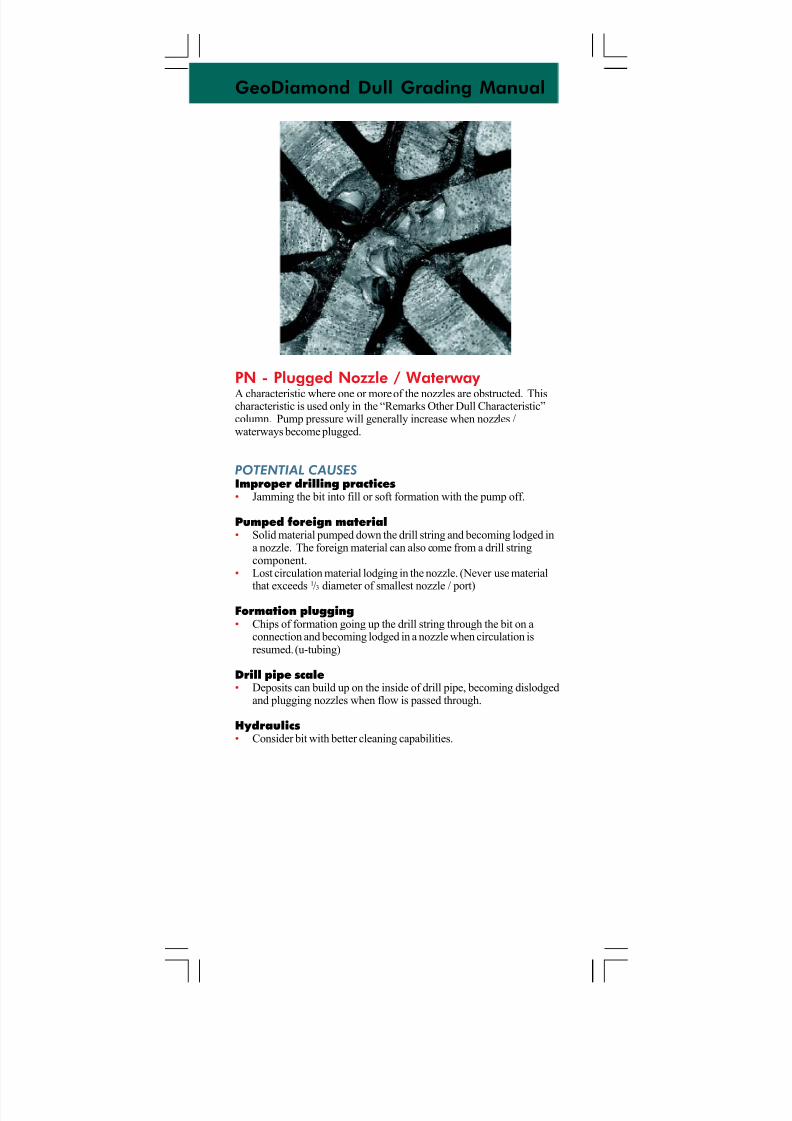
PN - Plugged Nozzle / Waterway A characteristic where one or more of the nozzles are obstructed. Thischaracteristic is used only in the “Remarks Other Dull Characteristic”column. Pump pressure will generally increase when nozzles /waterways become plugged.
POTENTIAL CAUSES
Improper drilling practices• Jamming the bit into fill or soft formation with the pump off.
Pumped foreign material• Solid material pumped down the drill string and becoming lodged in
a nozzle. The foreign material can also come from a drill stringcomponent.
• Lost circulation material lodging in the nozzle. (Never use material
that exceeds1
/3 diameter of smallest nozzle / port)
Formation plugging• Chips of formation going up the drill string through the bit on a
connection and becoming lodged in a nozzle when circulation isresumed. (u-tubing)
Drill pipe scale• Deposits can build up on the inside of drill pipe, becoming dislodged
and plugging nozzles when flow is passed through.
Hydraulics• Consider bit with better cleaning capabilities.
7/11/2019 Bit Dull Grade
http://slidepdf.com/reader/full/bit-dull-grade 9/99
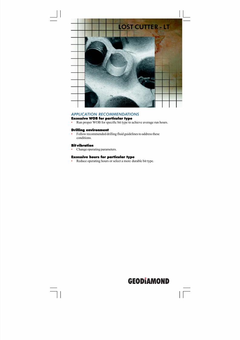
LOST CUTTER - LT
APPLICATION RECOMMENDATIONS
Excessive WOB for particular type• Run proper WOB for specific bit type to achieve average run hours.
Drilling environment• Follow recommended drilling fluid guidelines to address these
conditions.
Bit vibration• Change operating parameters.
Excessive hours for particular type• Reduce operating hours or select a more durable bit type.
7/11/2019 Bit Dull Grade
http://slidepdf.com/reader/full/bit-dull-grade 10/99
GeoDiamond Dull Grading Manual
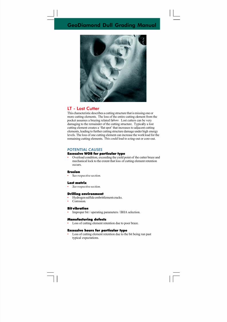
LT - Lost Cutter This characteristic describes a cutting structure that is missing one or more cutting elements. The loss of the entire cutting element from the
pocket assumes a brazing related failure. Lost cutters can be verydamaging to the remainder of the cutting structure. Typically a lostcutting element creates a ‘flat spot’ that increases to adjacent cuttingelements, leading to further cutting structure damage under high energylevels. The loss of one cutting element can increase the workload for theremaining cutting elements. This could lead to a ring-out or core-out.
POTENTIAL CAUSES
Excessive WOB for particular type• Overload condition, exceeding the yield point of the cutter braze and
mechanical lock to the extent that loss of cutting element retentionoccurs.
Erosion• See respective section.
Lost matrix • See respective section.
Drilling environment• Hydrogen sulfide embrittlement cracks.• Corrosion.
Bit vibration• Improper bit / operating parameters / BHA selection.
Manufacturing defects• Loss of cutting element retention due to poor braze.
Excessive hours for particular type• Loss of cutting element retention due to the bit being run past
typical expectations.
7/11/2019 Bit Dull Grade
http://slidepdf.com/reader/full/bit-dull-grade 11/99
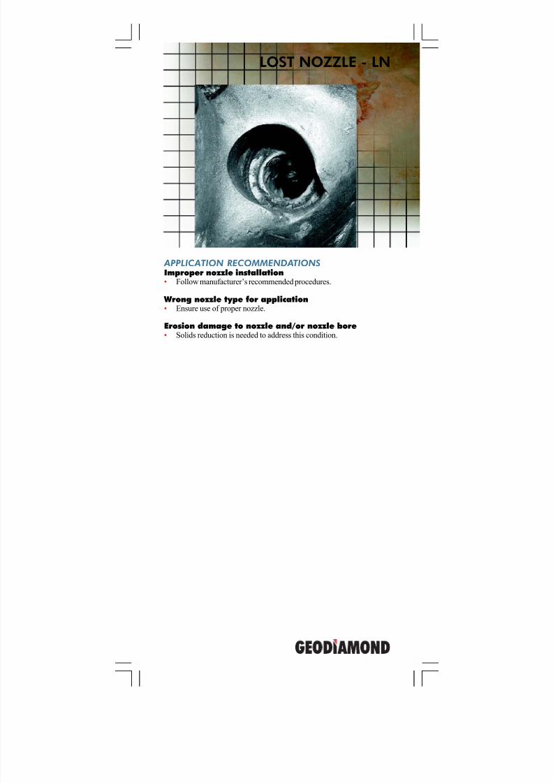
LOST NOZZLE - LN
APPLICATION RECOMMENDATIONS
Improper nozzle installation• Follow manufacturer’s recommended procedures.
Wrong nozzle type for application• Ensure use of proper nozzle.
Erosion damage to nozzle and/or nozzle bore• Solids reduction is needed to address this condition.
7/11/2019 Bit Dull Grade
http://slidepdf.com/reader/full/bit-dull-grade 12/99
GeoDiamond Dull Grading Manual
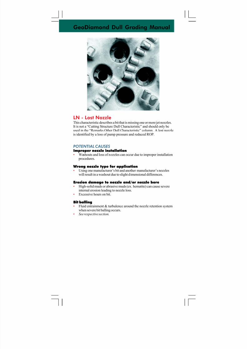
LN - Lost NozzleThis characteristic describes a bit that is missing one or more jet nozzles.It is not a “Cutting Structure Dull Characteristic” and should only beused in the “Remarks Other Dull Characteristic” column. A lost nozzleis identified by a loss of pump pressure and reduced ROP.
POTENTIAL CAUSES
Improper nozzle installation• Washouts and loss of nozzles can occur due to improper installation
procedures.
Wrong nozzle type for application• Using one manufacturer’s bit and another manufacturer’s nozzles
will result in a washout due to slight dimensional differences.
Erosion damage to nozzle and/or nozzle bore• High-solid muds or abrasive muds (ex. hematite) can cause severeinternal erosion leading to nozzle loss.
• Excessive hours on bit.
Bit balling• Fluid entrainment & turbulence around the nozzle retention system
when severe bit balling occurs.• See respective section.
7/11/2019 Bit Dull Grade
http://slidepdf.com/reader/full/bit-dull-grade 13/99
APPLICATION RECOMMENDATIONS
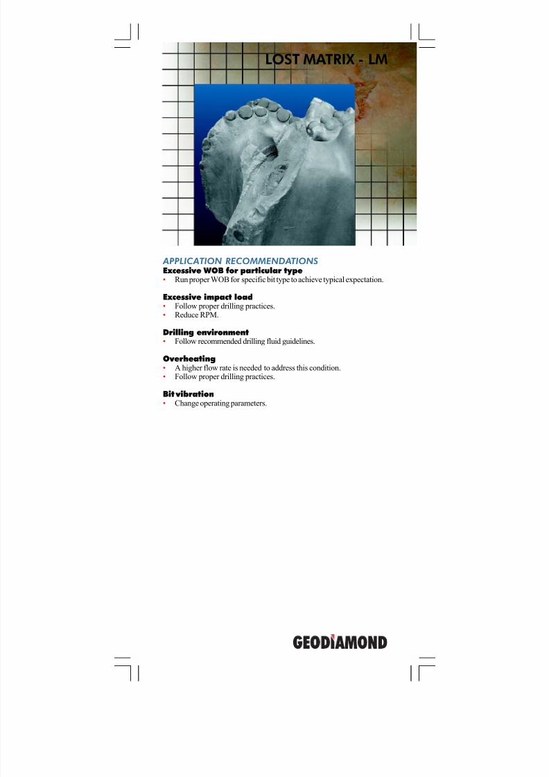
Excessive WOB for particular type• Run proper WOB for specific bit type to achieve typical expectation.
Excessive impact load• Follow proper drilling practices.• Reduce RPM.
Drilling environment• Follow recommended drilling fluid guidelines.
Overheating• A higher flow rate is needed to address this condition.• Follow proper drilling practices.
Bit vibration• Change operating parameters.
LOST MATRIX - LM
7/11/2019 Bit Dull Grade
http://slidepdf.com/reader/full/bit-dull-grade 14/99
GeoDiamond Dull Grading Manual
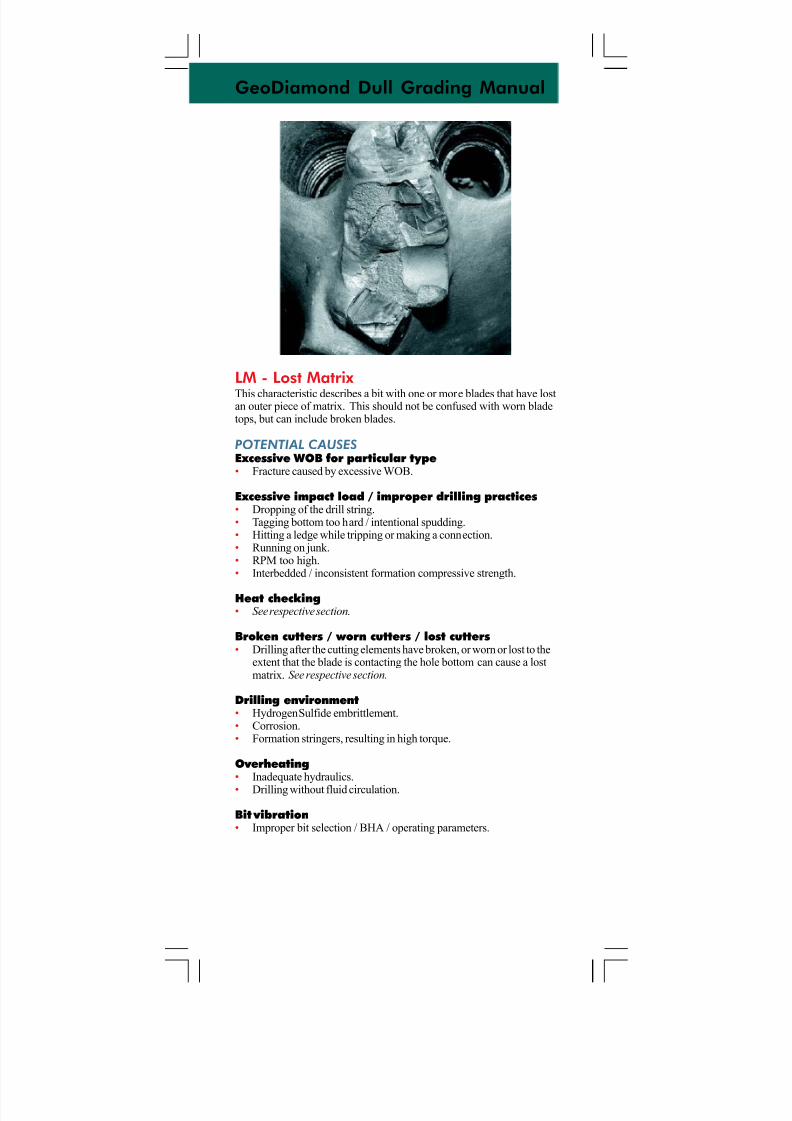
LM - Lost Matrix This characteristic describes a bit with one or more blades that have lostan outer piece of matrix. This should not be confused with worn bladetops, but can include broken blades.
POTENTIAL CAUSES
Excessive WOB for particular type• Fracture caused by excessive WOB.
Excessive impact load / improper drilling practices• Dropping of the drill string.• Tagging bottom too hard / intentional spudding.• Hitting a ledge while tripping or making a connection.• Running on junk.• RPM too high.• Interbedded / inconsistent formation compressive strength.
Heat checking• See respective section.
Broken cutters / worn cutters / lost cutters• Drilling after the cutting elements have broken, or worn or lost to the
extent that the blade is contacting the hole bottom can cause a lostmatrix. See respective section.
Drilling environment• Hydrogen Sulfide embrittlement.• Corrosion.• Formation stringers, resulting in high torque.
Overheating• Inadequate hydraulics.
• Drilling without fluid circulation.
Bit vibration• Improper bit selection / BHA / operating parameters.
7/11/2019 Bit Dull Grade
http://slidepdf.com/reader/full/bit-dull-grade 15/99
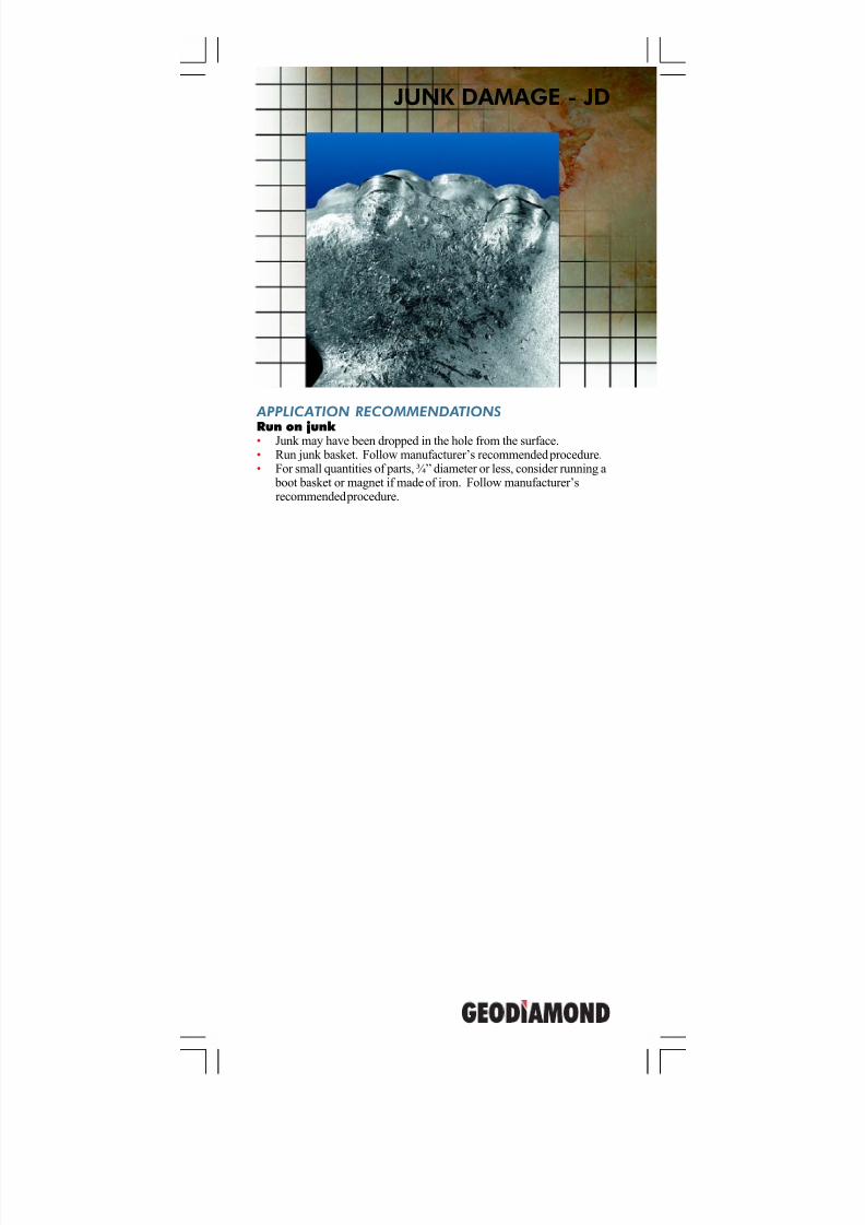
JUNK DAMAGE - JD
APPLICATION RECOMMENDATIONS
Run on junk • Junk may have been dropped in the hole from the surface.• Run junk basket. Follow manufacturer’s recommended procedure.• For small quantities of parts, ¾” diameter or less, consider running a
boot basket or magnet if made of iron. Follow manufacturer’srecommended procedure.

7/11/2019 Bit Dull Grade
http://slidepdf.com/reader/full/bit-dull-grade 16/99
GeoDiamond Dull Grading Manual
JD - Junk DamageA condition where the bit has indentations or cutter damage caused bycontact with objects other than formation. It is to be used in the“Remarks Other Dull Characteristics” column when describing damageto a bit knowingly caused by external sources or junk.
POTENTIAL CAUSES
Run on junk • Junk dropped in the hole from the surface (tong dies, tools, etc.).• Junk from the drill string (reamer pins, stabilizer blades, etc.)• Junk from a previous bit run (tungsten carbide inserts, ball bearings,
cutters, etc.).• Junk from the bit itself.• Damage due to contact with casing.• Junk from casing float equipment.• Damage caused by whipstock, casing windows, etc.
7/11/2019 Bit Dull Grade
http://slidepdf.com/reader/full/bit-dull-grade 17/99
APPLICATION RECOMMENDATIONS
Insufficient fluid flow • Refer to minimum GPM for size bit.• Consider bit design with improved hydraulic distribution.• Consider running higher nozzle count.
Reaming a slightly underguage hole at high RPM• Ream using very light WOB and low RPM. A hole in a slightly
underguage condition requires a lesser amount of WOB than a holein a greater under gauge condition. For example, a hole 1/16”underguage requires less WOB in order to not damage the bit than ahole 1/2” underguage.
Drilling at high RPM• Investigate use of bit with more abrasion resistant design.• Consider use of Quick cutters.• Select more abrasion resistant cutters.• Reduce RPM while drilling abrasive formations.
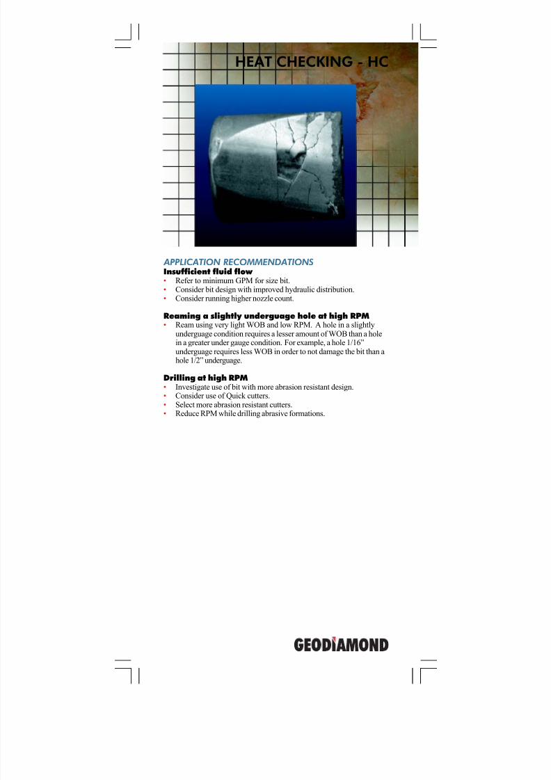
HEAT CHECKING - HC
7/11/2019 Bit Dull Grade
http://slidepdf.com/reader/full/bit-dull-grade 18/99
GeoDiamond Dull Grading Manual
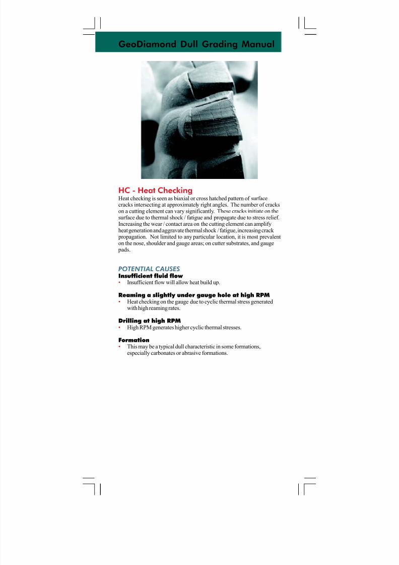
HC - Heat CheckingHeat checking is seen as biaxial or cross hatched pattern of surfacecracks intersecting at approximately right angles. The number of crackson a cutting element can vary significantly. These cracks initiate on thesurface due to thermal shock / fatigue and propagate due to stress relief.Increasing the wear / contact area on the cutting element can amplifyheat generation and aggravate thermal shock / fatigue, increasing crack
propagation. Not limited to any particular location, it is most prevalenton the nose, shoulder and gauge areas; on cutter substrates, and gauge
pads.
POTENTIAL CAUSES
Insufficient fluid flow • Insufficient flow will allow heat build up.
Reaming a slightly under gauge hole at high RPM• Heat checking on the gauge due to cyclic thermal stress generatedwith high reaming rates.
Drilling at high RPM• High RPM generates higher cyclic thermal stresses.
Formation• This may be a typical dull characteristic in some formations,
especially carbonates or abrasive formations.
7/11/2019 Bit Dull Grade
http://slidepdf.com/reader/full/bit-dull-grade 19/99
APPLICATION RECOMMENDATIONS
Excessive hydraulics• Reduce the hydraulic energy level (jet velocity / HSI).• Increase nozzle count and improve hydraulic distribution.• Select a bit with an erosion protection feature. Matrix bits provide
better erosion resistance than steel bits.• Optimize TFA with erosion reduction in mind.
Abrasive formations• Select a bit with an erosive wear reduction feature.
Drilling environment• Follow recommended drilling fluid guidelines to reduce solids.• Select a bit with an erosive wear reduction feature.• Follow recommended drilling fluid guidelines to reduce corrosion.
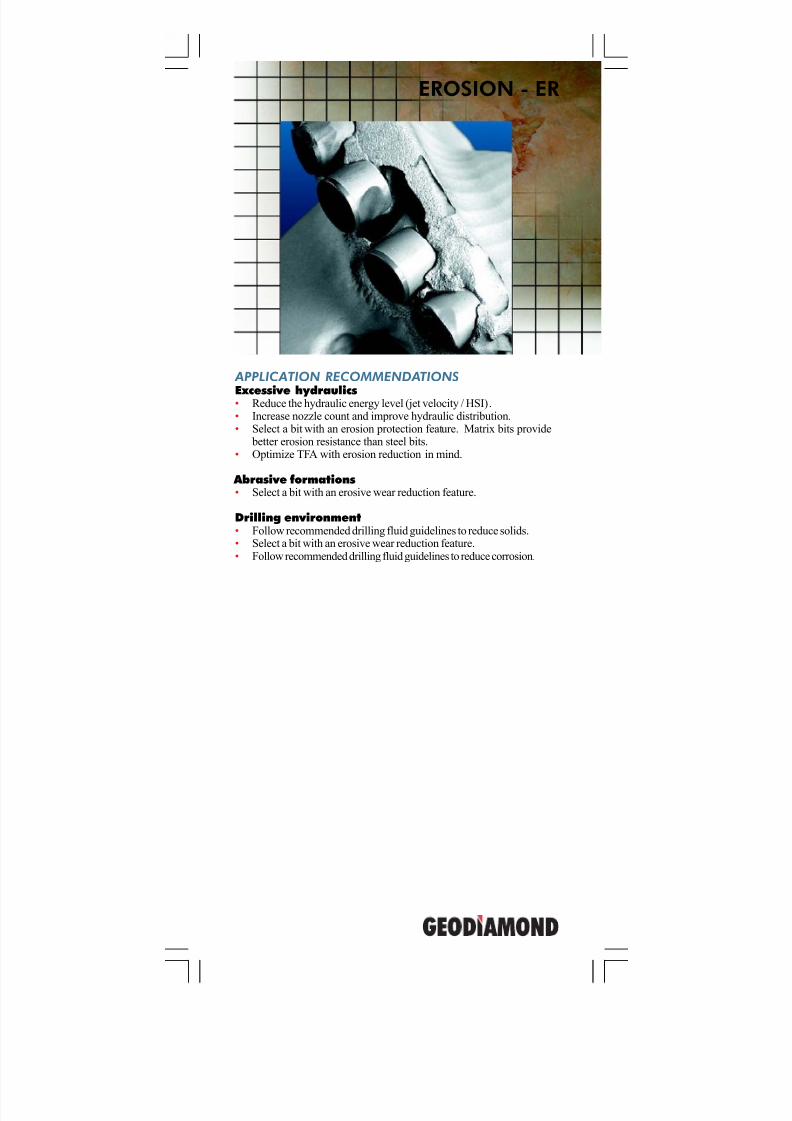
EROSION - ER
7/11/2019 Bit Dull Grade
http://slidepdf.com/reader/full/bit-dull-grade 20/99
GeoDiamond Dull Grading Manual
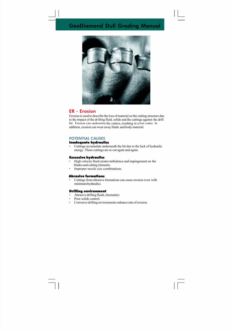
ER - ErosionErosion is used to describe the loss of material on the cutting structure dueto the impact of the drilling fluid, solids and the cuttings against the drill
bit. Erosion can undermine the cutters, resulting in a lost cutter. Inaddition, erosion can wear away blade and body material.
POTENTIAL CAUSES
Inadequate hydraulics• Cuttings accumulate underneath the bit due to the lack of hydraulic
energy. These cuttings are re-cut again and again.
Excessive hydraulics• High velocity fluid creates turbulence and impingement on the
blades and cutting elements.• Improper nozzle size combinations.
Abrasive formations• Cuttings from abrasive formations can cause erosion even with
minimum hydraulics.
Drilling environment• Abrasive drilling fluids. (hematite)• Poor solids control.• Corrosive drilling environments enhance rate of erosion.
7/11/2019 Bit Dull Grade
http://slidepdf.com/reader/full/bit-dull-grade 21/99
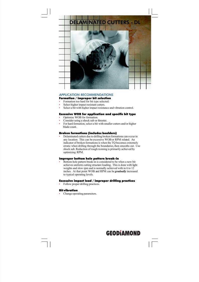
DELAMINATED CUTTERS - DL
APPLICATION RECOMMENDATIONS
Formation / improper bit selection• Formation too hard for bit type selected.• Select higher impact resistant cutters.• Select a bit with higher impact resistance and vibration control.
Excessive WOB for application and specific bit type• Optimize WOB for formation.• Consider using a shock sub or thruster.• For hard formation, select a bit with smaller cutters and/or higher
blade count.
Broken formations (includes boulders)• Delaminated cutters due to drilling broken formations can occur in
any location. This can be excessive WOB or RPM related. Anindicator of broken formations is when the TQ becomes extremelyerratic when drilling through the boundaries, then smooths out. Use
shock sub. Reduction of rough running is primarily achieved byoptimizing RPM.
Improper bottom hole pattern break-in• Bottom hole pattern break-in is considered to be when a new bit
achieves uniform cutting structure loading. This is done with lightweights and slow rpm and is normally achieved with in 6 to 12inches. At that point WOB and RPM can be gradually increasedto typical operating levels.
Excessive impact load / improper drilling practices• Follow proper drilling practices.
Bit vibration• Change operating parameters.
7/11/2019 Bit Dull Grade
http://slidepdf.com/reader/full/bit-dull-grade 22/99
GeoDiamond Dull Grading Manual
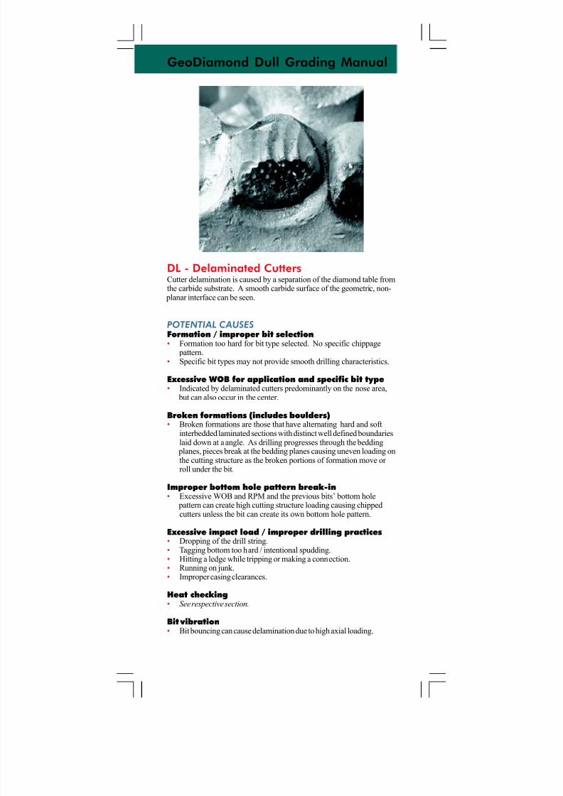
DL - Delaminated CuttersCutter delamination is caused by a separation of the diamond table fromthe carbide substrate. A smooth carbide surface of the geometric, non-
planar interface can be seen.
POTENTIAL CAUSES
Formation / improper bit selection• Formation too hard for bit type selected. No specific chippage
pattern.• Specific bit types may not provide smooth drilling characteristics.
Excessive WOB for application and specific bit type• Indicated by delaminated cutters predominantly on the nose area,
but can also occur in the center.
Broken formations (includes boulders)• Broken formations are those that have alternating hard and softinterbedded laminated sections with distinct well defined boundarieslaid down at a angle. As drilling progresses through the bedding
planes, pieces break at the bedding planes causing uneven loading onthe cutting structure as the broken portions of formation move or roll under the bit.
Improper bottom hole pattern break-in• Excessive WOB and RPM and the previous bits’ bottom hole
pattern can create high cutting structure loading causing chippedcutters unless the bit can create its own bottom hole pattern.
Excessive impact load / improper drilling practices• Dropping of the drill string.• Tagging bottom too hard / intentional spudding.
• Hitting a ledge while tripping or making a connection.• Running on junk.• Improper casing clearances.
Heat checking• See respective section.
Bit vibration• Bit bouncing can cause delamination due to high axial loading.
7/11/2019 Bit Dull Grade
http://slidepdf.com/reader/full/bit-dull-grade 23/99
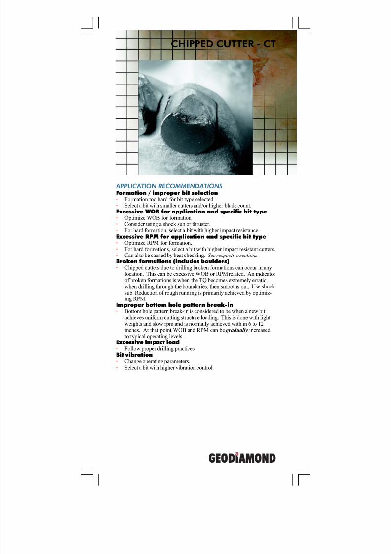
CHIPPED CUTTER - CT
APPLICATION RECOMMENDATIONS
Formation / improper bit selection• Formation too hard for bit type selected.• Select a bit with smaller cutters and/or higher blade count.Excessive WOB for application and specific bit type• Optimize WOB for formation.• Consider using a shock sub or thruster.• For hard formation, select a bit with higher impact resistance.Excessive RPM for application and specific bit type• Optimize RPM for formation.• For hard formations, select a bit with higher impact resistant cutters.• Can also be caused by heat checking. See respective sections.Broken formations (includes boulders)• Chipped cutters due to drilling broken formations can occur in any
location. This can be excessive WOB or RPM related. An indicator of broken formations is when the TQ becomes extremely erraticwhen drilling through the boundaries, then smooths out. Use shock
sub. Reduction of rough running is primarily achieved by optimiz-ing RPM.
Improper bottom hole pattern break-in• Bottom hole pattern break-in is considered to be when a new bit
achieves uniform cutting structure loading. This is done with lightweights and slow rpm and is normally achieved with in 6 to 12inches. At that point WOB and RPM can be gradually increasedto typical operating levels.
Excessive impact load• Follow proper drilling practices.Bit vibration• Change operating parameters.• Select a bit with higher vibration control.
7/11/2019 Bit Dull Grade
http://slidepdf.com/reader/full/bit-dull-grade 24/99
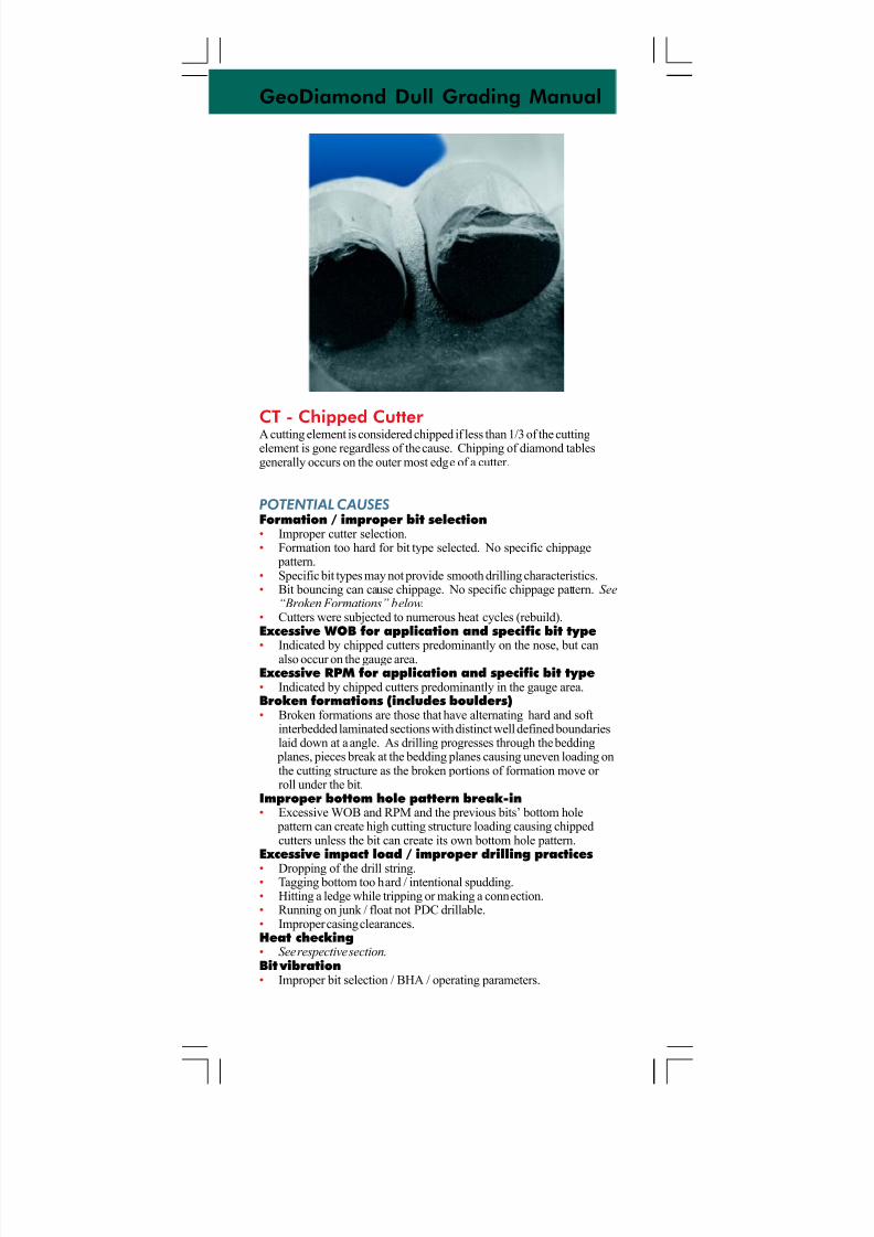
GeoDiamond Dull Grading Manual
CT - Chipped Cutter A cutting element is considered chipped if less than 1/3 of the cuttingelement is gone regardless of the cause. Chipping of diamond tablesgenerally occurs on the outer most edge of a cutter.
POTENTIAL CAUSES
Formation / improper bit selection• Improper cutter selection.• Formation too hard for bit type selected. No specific chippage
pattern.• Specific bit types may not provide smooth drilling characteristics.• Bit bouncing can cause chippage. No specific chippage pattern. See
“Broken Formations” below.• Cutters were subjected to numerous heat cycles (rebuild).Excessive WOB for application and specific bit type
• Indicated by chipped cutters predominantly on the nose, but canalso occur on the gauge area.Excessive RPM for application and specific bit type• Indicated by chipped cutters predominantly in the gauge area.Broken formations (includes boulders)• Broken formations are those that have alternating hard and soft
interbedded laminated sections with distinct well defined boundarieslaid down at a angle. As drilling progresses through the bedding
planes, pieces break at the bedding planes causing uneven loading onthe cutting structure as the broken portions of formation move or roll under the bit.
Improper bottom hole pattern break-in• Excessive WOB and RPM and the previous bits’ bottom hole
pattern can create high cutting structure loading causing chippedcutters unless the bit can create its own bottom hole pattern.
Excessive impact load / improper drilling practices
• Dropping of the drill string.• Tagging bottom too hard / intentional spudding.• Hitting a ledge while tripping or making a connection.• Running on junk / float not PDC drillable.• Improper casing clearances.Heat checking• See respective section.Bit vibration• Improper bit selection / BHA / operating parameters.
7/11/2019 Bit Dull Grade
http://slidepdf.com/reader/full/bit-dull-grade 25/99
CORED - CR
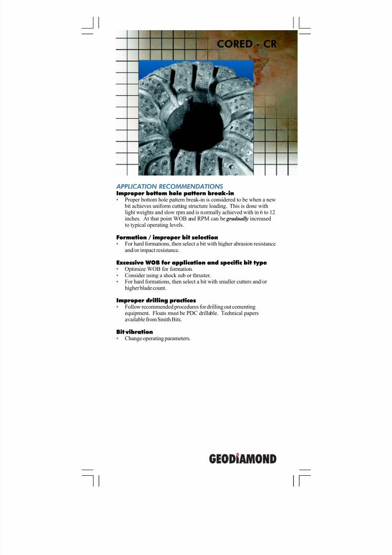
APPLICATION RECOMMENDATIONS
Improper bottom hole pattern break-in• Proper bottom hole pattern break-in is considered to be when a new bit achieves uniform cutting structure loading. This is done withlight weights and slow rpm and is normally achieved with in 6 to 12inches. At that point WOB and RPM can be gradually increasedto typical operating levels.
Formation / improper bit selection• For hard formations, then select a bit with higher abrasion resistance
and/or impact resistance.
Excessive WOB for application and specific bit type• Optimize WOB for formation.• Consider using a shock sub or thruster.• For hard formations, then select a bit with smaller cutters and/or
higher blade count.
Improper drilling practices• Follow recommended procedures for drilling out cementing
equipment. Floats must be PDC drillable. Technical papersavailable from Smith Bits.
Bit vibration• Change operating parameters.
7/11/2019 Bit Dull Grade
http://slidepdf.com/reader/full/bit-dull-grade 26/99
GeoDiamond Dull Grading Manual
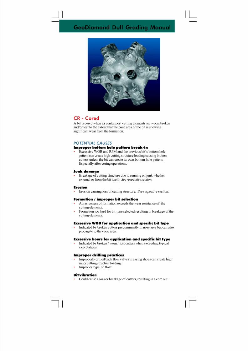
CR - CoredA bit is cored when its centermost cutting elements are worn, brokenand/or lost to the extent that the cone area of the bit is showingsignificant wear from the formation.
POTENTIAL CAUSES
Improper bottom hole pattern break-in• Excessive WOB and RPM and the previous bit’s bottom hole
pattern can create high cutting structure loading causing brokencutters unless the bit can create its own bottom hole pattern,Especially after coring operations.
Junk damage• Breakage of cutting structure due to running on junk whether
external or from the bit itself. See respective section.
Erosion• Erosion causing loss of cutting structure. See respective section.
Formation / improper bit selection• Abrasiveness of formation exceeds the wear resistance of the
cutting elements.• Formation too hard for bit type selected resulting in breakage of the
cutting elements.
Excessive WOB for application and specific bit type• Indicated by broken cutters predominantly in nose area but can also
propagate to the cone area.
Excessive hours for application and specific bit type• Indicated by broken / worn / lost cutters when exceeding typical
expectations.
Improper drilling practices• Improperly drilled back flow valves in casing shoes can create high
inner cutting structure loading.• Improper type of float.
Bit vibration• Could cause a loss or breakage of cutters, resulting in a core out.
7/11/2019 Bit Dull Grade
http://slidepdf.com/reader/full/bit-dull-grade 27/99
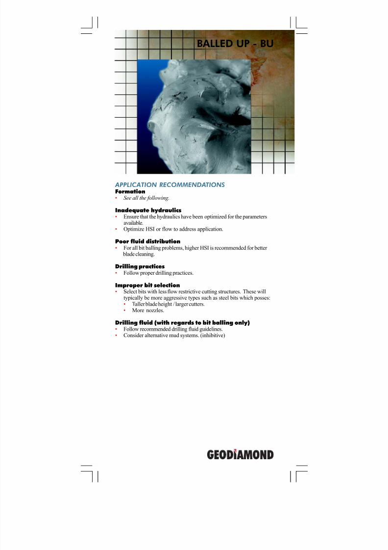
APPLICATION RECOMMENDATIONS
Formation• See all the following.
Inadequate hydraulics• Ensure that the hydraulics have been optimized for the parameters
available.• Optimize HSI or flow to address application.
Poor fluid distribution• For all bit balling problems, higher HSI is recommended for better
blade cleaning.
Drilling practices• Follow proper drilling practices.
Improper bit selection• Select bits with less flow restrictive cutting structures. These will
typically be more aggressive types such as steel bits which posses:• Taller blade height / larger cutters.• More nozzles.
Drilling fluid (with regards to bit balling only)• Follow recommended drilling fluid guidelines.• Consider alternative mud systems. (inhibitive)
BALLED UP - BU
7/11/2019 Bit Dull Grade
http://slidepdf.com/reader/full/bit-dull-grade 28/99
GeoDiamond Dull Grading Manual
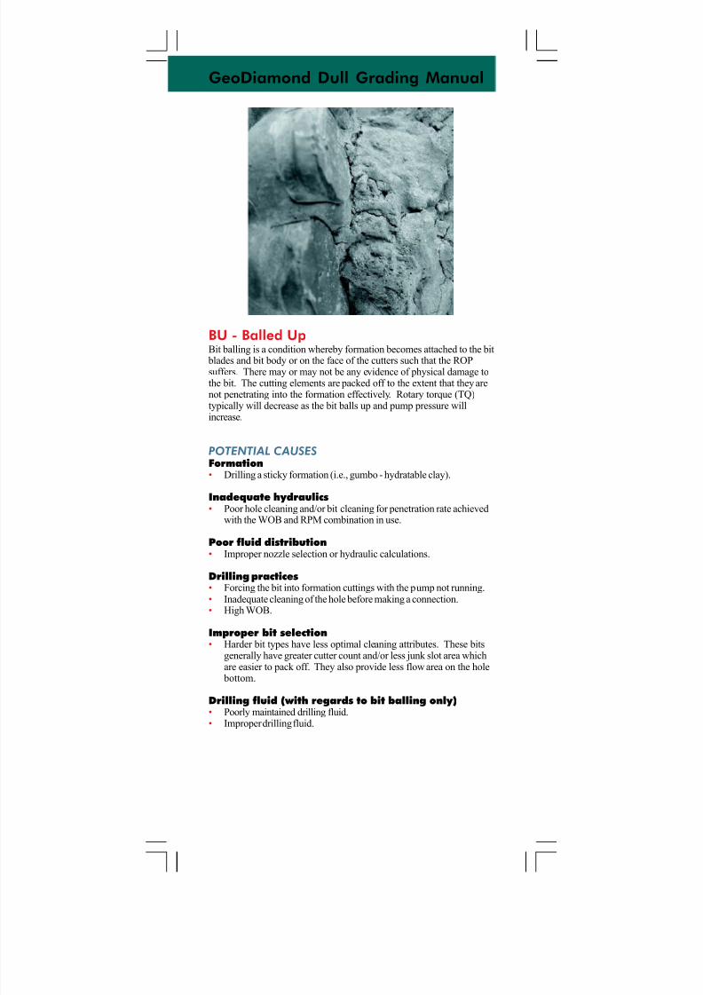
BU - Balled UpBit balling is a condition whereby formation becomes attached to the bit
blades and bit body or on the face of the cutters such that the ROPsuffers. There may or may not be any evidence of physical damage tothe bit. The cutting elements are packed off to the extent that they arenot penetrating into the formation effectively. Rotary torque (TQ)typically will decrease as the bit balls up and pump pressure willincrease.
POTENTIAL CAUSES
Formation• Drilling a sticky formation (i.e., gumbo - hydratable clay).
Inadequate hydraulics• Poor hole cleaning and/or bit cleaning for penetration rate achieved
with the WOB and RPM combination in use.
Poor fluid distribution• Improper nozzle selection or hydraulic calculations.
Drilling practices• Forcing the bit into formation cuttings with the pump not running.• Inadequate cleaning of the hole before making a connection.• High WOB.
Improper bit selection• Harder bit types have less optimal cleaning attributes. These bits
generally have greater cutter count and/or less junk slot area whichare easier to pack off. They also provide less flow area on the hole
bottom.
Drilling fluid (with regards to bit balling only)• Poorly maintained drilling fluid.• Improper drilling fluid.
7/11/2019 Bit Dull Grade
http://slidepdf.com/reader/full/bit-dull-grade 29/99
BROKEN CUTTERS - BT
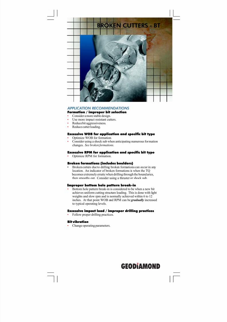
APPLICATION RECOMMENDATIONS
Formation / improper bit selection• Consider a more stable design.• Use more impact resistant cutters.• Reduce bit aggressiveness.• Reduce cutter loading.
Excessive WOB for application and specific bit type• Optimize WOB for formation.• Consider using a shock sub when anticipating numerous formation
changes. See broken formations.
Excessive RPM for application and specific bit type• Optimize RPM for formation.
Broken formations (includes boulders)• Broken cutters due to drilling broken formations can occur in any
location. An indicator of broken formations is when the TQ becomes extremely erratic when drilling through the boundaries,then smooths out. Consider using a thruster or shock sub.
IIIIImproper bottom hole pattern break-in• Bottom hole pattern break-in is considered to be when a new bit
achieves uniform cutting structure loading. This is done with lightweights and slow rpm and is normally achieved within 6 to 12inches. At that point WOB and RPM can be gradually increasedto typical operating levels.
Excessive impact load / improper drilling practices• Follow proper drilling practices.
Bit vibration
• Change operating parameters.
7/11/2019 Bit Dull Grade
http://slidepdf.com/reader/full/bit-dull-grade 30/99
GeoDiamond Dull Grading Manual
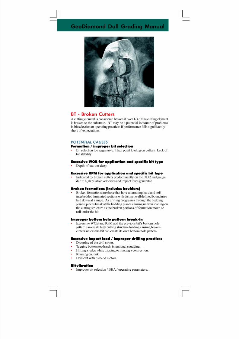
BT - Broken CuttersA cutting element is considered broken if over 1/3 of the cutting elementis broken to the substrate. BT may be a potential indicator of problemsin bit selection or operating practices if performance falls significantlyshort of expectations.
POTENTIAL CAUSES
Formation / improper bit selection• Bit selection too aggressive. High point loading on cutters. Lack of
bit stability.
Excessive WOB for application and specific bit type• Depth of cut too deep.
Excessive RPM for application and specific bit type
• Indicated by broken cutters predominantly on the ODR and gaugedue to high relative velocities and impact force generated .
Broken formations (includes boulders)• Broken formations are those that have alternating hard and soft
interbedded laminated sections with distinct well defined boundarieslaid down at a angle. As drilling progresses through the bedding
planes, pieces break at the bedding planes causing uneven loading onthe cutting structure as the broken portions of formation move or roll under the bit.
Improper bottom hole pattern break-in• Excessive WOB and RPM and the previous bit’s bottom hole
pattern can create high cutting structure loading causing brokencutters unless the bit can create its own bottom hole pattern.
Excessive impact load / improper drilling practices• Dropping of the drill string.• Tagging bottom too hard / intentional spudding.• Hitting a ledge while tripping or making a connection.• Running on junk.• Drill-out with hi-bend motors.
Bit vibration• Improper bit selection / BHA / operating parameters.
7/11/2019 Bit Dull Grade
http://slidepdf.com/reader/full/bit-dull-grade 31/99
BOND FAILURE - BF
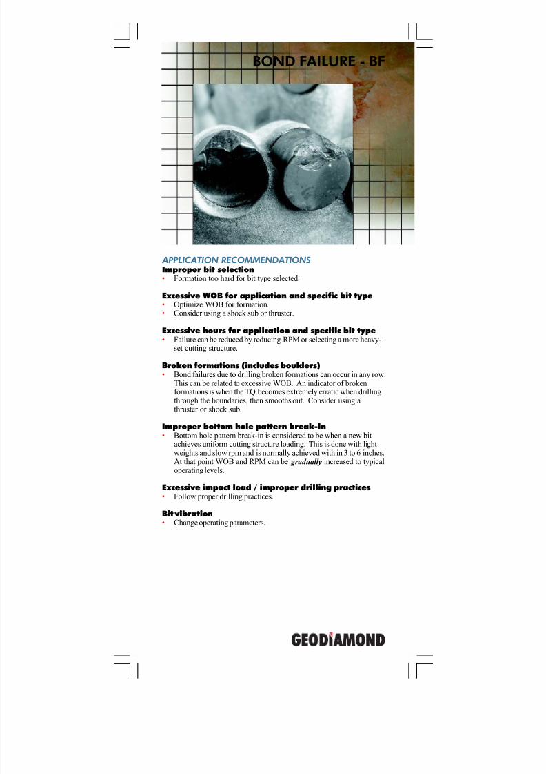
APPLICATION RECOMMENDATIONS
Improper bit selection• Formation too hard for bit type selected.
Excessive WOB for application and specific bit type• Optimize WOB for formation.• Consider using a shock sub or thruster.
Excessive hours for application and specific bit type• Failure can be reduced by reducing RPM or selecting a more heavy-
set cutting structure.
Broken formations (includes boulders)• Bond failures due to drilling broken formations can occur in any row.
This can be related to excessive WOB. An indicator of brokenformations is when the TQ becomes extremely erratic when drillingthrough the boundaries, then smooths out. Consider using a
thruster or shock sub.
Improper bottom hole pattern break-in• Bottom hole pattern break-in is considered to be when a new bit
achieves uniform cutting structure loading. This is done with lightweights and slow rpm and is normally achieved with in 3 to 6 inches.At that point WOB and RPM can be gradually increased to typicaloperating levels.
Excessive impact load / improper drilling practices• Follow proper drilling practices.
Bit vibration• Change operating parameters.
7/11/2019 Bit Dull Grade
http://slidepdf.com/reader/full/bit-dull-grade 32/99
GeoDiamond Dull Grading Manual
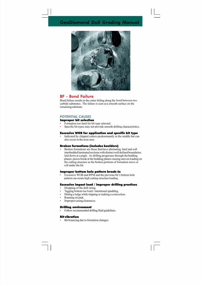
BF - Bond FailureBond failure results in the cutter failing along the bond between twocarbide substrates. The failure is seen as a smooth surface on theremaining substrate.
POTENTIAL CAUSES
Improper bit selection• Formation too hard for bit type selected.• Specific bit types may not provide smooth drilling characteristics.
Excessive WOB for application and specific bit type• Indicated by chipped cutters predominantly in the middle but can
also occur in the nose area.
Broken formations (includes boulders)
• Broken formations are those that have alternating hard and softinterbedded laminated sections with distinct well defined boundarieslaid down at a angle. As drilling progresses through the bedding
planes, pieces break at the bedding planes causing uneven loading onthe cutting structure as the broken portions of formation move or roll under the bit.
Improper bottom hole pattern break-in• Excessive WOB and RPM and the previous bit’s bottom hole
pattern can create high cutting structure loading.
Excessive impact load / improper drilling practices• Dropping of the drill string.• Tagging bottom too hard / intentional spudding.• Hitting a ledge while tripping or making a connection.• Running on junk.
• Improper casing clearances.
Drilling environment• Follow recommended drilling fluid guidelines.
Bit vibration• Bit bouncing due to formation changes.
7/11/2019 Bit Dull Grade
http://slidepdf.com/reader/full/bit-dull-grade 33/99
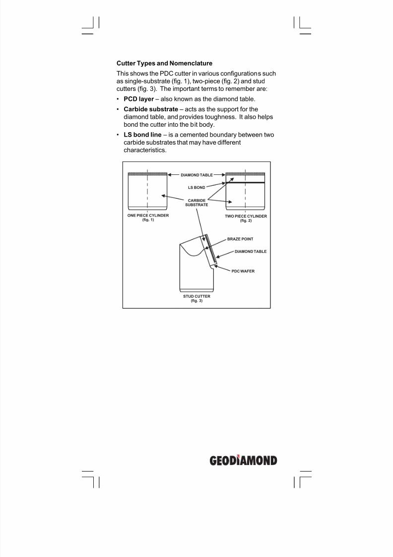
Cutter Types and Nomenclature
This shows the PDC cutter in various configurations such
as single-substrate (fig. 1), two-piece (fig. 2) and stud
cutters (fig. 3). The important terms to remember are:
• PCD layer – also known as the diamond table.
• Carbide substrate – acts as the support for the
diamond table, and provides toughness. It also helps
bond the cutter into the bit body.
• LS bond line – is a cemented boundary between two
carbide substrates that may have different
characteristics.
STUD CUTTER(fig. 3)
TWO PIECE CYLINDER(fig. 2)
ONE PIECE CYLINDER(fig. 1)
BRAZE POINT
DIAMOND TABLE
DIAMOND TABLE
PDC WAFER
CARBIDESUBSTRATE
LS BOND
7/11/2019 Bit Dull Grade
http://slidepdf.com/reader/full/bit-dull-grade 34/99
GeoDiamond Dull Grading Manual
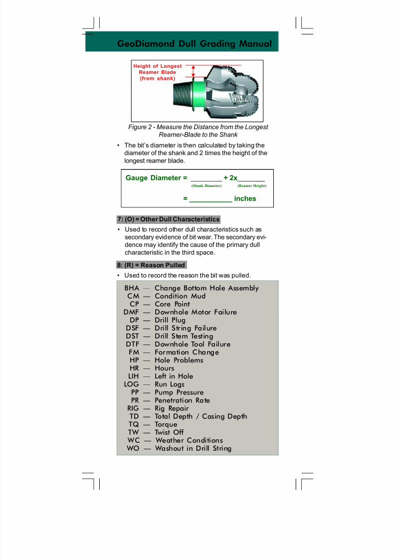
Figure 2 - Measure the Distance from the Longest
Reamer-Blade to the Shank
• The bit’s diameter is then calculated by taking the
diameter of the shank and 2 times the height of the
longest reamer blade.
8: (R) = Reason Pulled
• Used to record the reason the bit was pulled.
Gauge Diameter = ________ + 2x_______ (Shank Diameter) (Reamer Height)
= ___________ inches
7: (O) = Other Dull Characteristics
• Used to record other dull characteristics such as
secondary evidence of bit wear. The secondary evi-
dence may identify the cause of the primary dull
characteristic in the third space.
BHA — Change Bottom Hole Assembly
CM — Condition MudCP — Core Point
DMF — Downhole Motor FailureDP — Drill Plug
DSF — Drill String FailureDST — Drill Stem TestingDTF — Downhole Tool FailureFM — Formation ChangeHP — Hole ProblemsHR — HoursLIH — Left in Hole
LOG — Run Logs
PP — Pump PressurePR — Penetration Rate
RIG — Rig Repair TD — Total Depth / Casing DepthTQ — TorqueTW — Twist Off
WC — Weather Conditions WO — Washout in Drill String
Height of Longest
Reamer Blade
(from shank)
7/11/2019 Bit Dull Grade
http://slidepdf.com/reader/full/bit-dull-grade 35/99
5: (B) = Bearings / Seals
This space is used only for roller cone bits. It will always
be marked “X” for fixed cutter bits.
6: (G) = Amount Undergauge
• Used to record the condition of the bit gauge. It is
based upon nominal ring gauge (ensure that a PDC
and not roller cone ring gauge is used as tolerances
between the two are different).
– “IN” is used if the bit is still in gauge.
– Otherwise, the amount the bit is undergauge is
recorded to the nearest 1/16th of an inch.
– For bi-centers, use the special bi-center gauge
measurement procedure below.
API tolerances for fixed cutter and roller cone bits
Nominal Bit Size (in.) Fixed Cutter Roller Cone
6 ¾ and smaller -0.015 to +0.00 -0.0 to +1/32
6 25/32 including 9 -0.020 to +0.00 -0.0 to +1/32
9 1/32 including 13 ¾ -0.030 to +0.00 -0.0 to +1/32
13 25/32 including 17 ½ -0.045 to +0.00 -0.0 to +1/16
17 17/32 and larger -0.063 to +0.00 -0.0 to +3/32
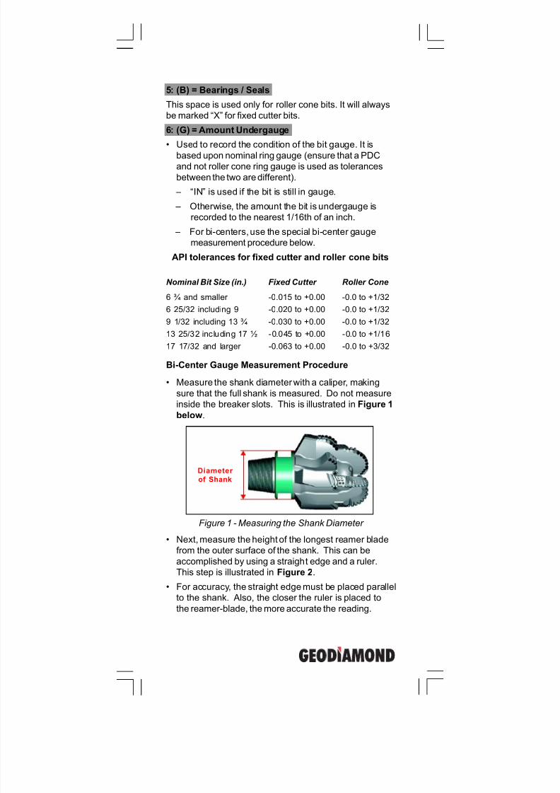
Bi-Center Gauge Measurement Procedure
• Measure the shank diameter with a caliper, making
sure that the full shank is measured. Do not measure
inside the breaker slots. This is illustrated in Figure 1
below.
Figure 1 - Measuring the Shank Diameter
• Next, measure the height of the longest reamer blade
from the outer surface of the shank. This can be
accomplished by using a straight edge and a ruler.
This step is illustrated in Figure 2.
• For accuracy, the straight edge must be placed parallel
to the shank. Also, the closer the ruler is placed to
the reamer-blade, the more accurate the reading.
Diameter
of Shank
7/11/2019 Bit Dull Grade
http://slidepdf.com/reader/full/bit-dull-grade 36/99
GeoDiamond Dull Grading Manual
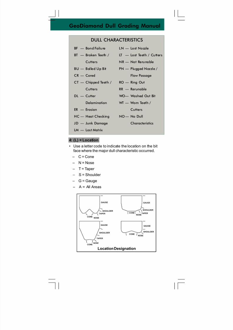
4: (L) = Location
• Use a letter code to indicate the location on the bit
face where the major dull characteristic occurred.
– C = Cone
– N = Nose
– T = Taper
– S = Shoulder
– G = Gauge
– A = All Areas
Location Designation
GAUGE GAUGE
GAUGEGAUGE
SHOULDERSHOULDER
SHOULDERSHOULDER
TAPER TAPER
TAPER
NOSE
NOSE
NOSE
NOSE
CONE
CONE
CONE
CONE
DULL CHARACTERISTICS
BF — Bond Failure
BT — Broken Teeth /
Cutters
BU — Balled Up Bit
CR — Cored
CT — Chipped Teeth /
Cutters
DL — Cutter
Delamination
ER — Erosion
HC — Heat Checking
JD — Junk Damage
LM — Lost Matrix
LN — Lost Nozzle
LT — Lost Teeth / Cutters
NR — Not Rerunable
PN — Plugged Nozzle /
Flow Passage
RO — Ring Out
RR — Rerunable
WO— Washed Out Bit
WT — Worn Teeth /
Cutters
NO — No Dull
Characteristics
7/11/2019 Bit Dull Grade
http://slidepdf.com/reader/full/bit-dull-grade 37/99
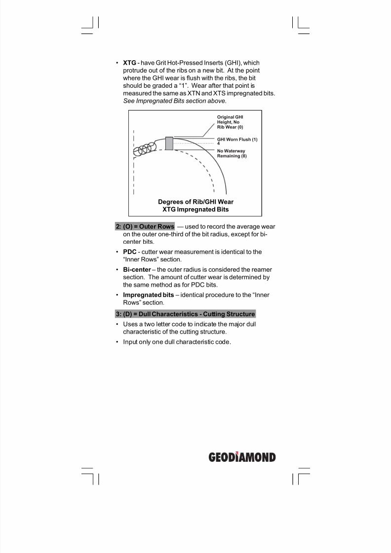
• XTG - have Grit Hot-Pressed Inserts (GHI), which
protrude out of the ribs on a new bit. At the point
where the GHI wear is flush with the ribs, the bit
should be graded a “1”. Wear after that point is
measured the same as XTN and XTS impregnated bits.
See Impregnated Bits section above.
2: (O) = Outer Rows — used to record the average wear
on the outer one-third of the bit radius, except for bi-
center bits.
• PDC - cutter wear measurement is identical to the
“Inner Rows” section.
• Bi-center – the outer radius is considered the reamer
section. The amount of cutter wear is determined by
the same method as for PDC bits.
• Impregnated bits – identical procedure to the “Inner
Rows” section.
Degrees of Rib/GHI Wear
XTG Impregnated Bits
Original GHIHeight, NoRib Wear (0)
No WaterwayRemaining (8)
GHI Worn Flush (1)4
3: (D) = Dull Characteristics - Cutting Structure
• Uses a two letter code to indicate the major dull
characteristic of the cutting structure.
• Input only one dull characteristic code.
7/11/2019 Bit Dull Grade
http://slidepdf.com/reader/full/bit-dull-grade 38/99
GeoDiamond Dull Grading Manual
Inner Radius
(Pilot)
Outer Radius
(Reamer)
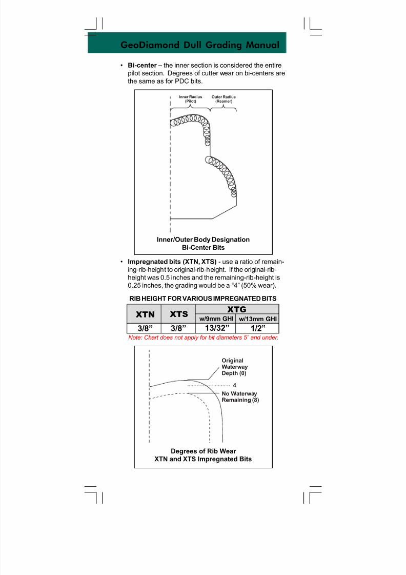
• Bi-center – the inner section is considered the entire
pilot section. Degrees of cutter wear on bi-centers are
the same as for PDC bits.
Inner/Outer Body Designation
Bi-Center Bits
• Impregnated bits (XTN, XTS) - use a ratio of remain-
ing-rib-height to original-rib-height. If the original-rib-
height was 0.5 inches and the remaining-rib-height is
0.25 inches, the grading would be a “4” (50% wear).
XTN XTSXTG
3/8” 3/8” 13/32” 1/2”
w/9mm GHI w/13mm GHI
RIB HEIGHT FOR VARIOUS IMPREGNATED BITS
Note: Chart does not apply for bit diameters 5” and under.
OriginalWaterwayDepth (0)
No WaterwayRemaining (8)
4
Degrees of Rib Wear
XTN and XTS Impregnated Bits
7/11/2019 Bit Dull Grade
http://slidepdf.com/reader/full/bit-dull-grade 39/99
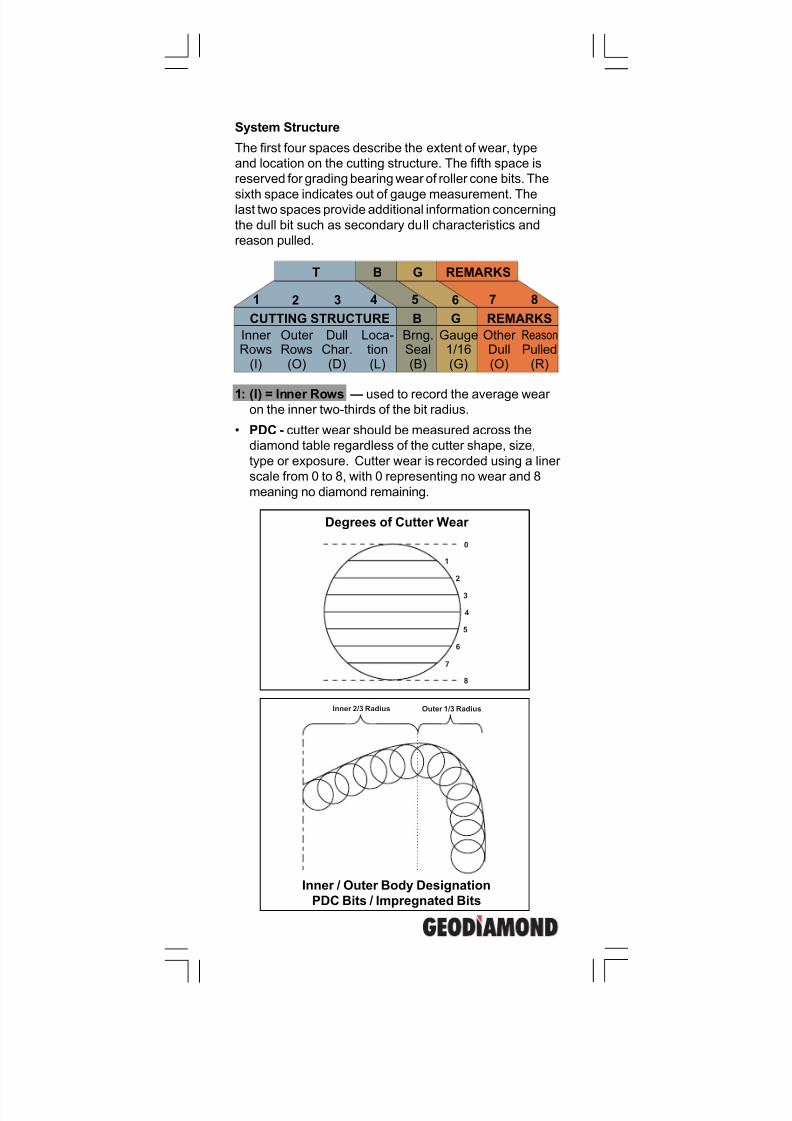
System Structure
The first four spaces describe the extent of wear, type
and location on the cutting structure. The fifth space is
reserved for grading bearing wear of roller cone bits. The
sixth space indicates out of gauge measurement. Thelast two spaces provide additional information concerning
the dull bit such as secondary dull characteristics and
reason pulled.
Inner Rows(I)
Outer Rows(O)
DullChar.(D)
Loca-tion(L)
Brng.Seal(B)
Gauge1/16(G)
Other Dull(O)
Reason
Pulled(R)
CUTTING STRUCTURE B G REMARKS
BT G REMARKS
1 2 3 4 5 6 7 8
1: (I) = Inner Rows — used to record the average wear on the inner two-thirds of the bit radius.
• PDC - cutter wear should be measured across the
diamond table regardless of the cutter shape, size,
type or exposure. Cutter wear is recorded using a liner
scale from 0 to 8, with 0 representing no wear and 8
meaning no diamond remaining.
Degrees of Cutter Wear
0
1
2
3
4
5
6
7
8
Inner 2/3 Radius Outer 1/3 Radius
Inner / Outer Body Designation
PDC Bits / Impregnated Bits
7/11/2019 Bit Dull Grade
http://slidepdf.com/reader/full/bit-dull-grade 40/99
GeoDiamond Dull Grading Manual
GeoDiamond is a subsidiary ofSmith Bits.
The GeoDiamond definitions and guidelines shown within are NOT IADC standards. They were createdsolely for internal purposes to reduce ambiguities andto improve our consistency in grading dull bits within
the current IADC structure.
Authors:
Stephen ErnstGlynn Krouse
Steve SouthlandMike Azar
Layout and Graphics:
IceBerg Graphics
P.O. Box 60068 • Houston, Texas 77205-0068
U.S. And Canada: 800/US SMITH • Tel. 281/443-3370
Fax: 281-233-5994 • Telex: 76-2517
Internet: http://www.smith.com
Copyright © 2001 Smith International, Inc.
All rights reserved.
ST-2067 • 25M • 01/01
7/11/2019 Bit Dull Grade
http://slidepdf.com/reader/full/bit-dull-grade 41/99
GEODIAMONDDULL GRADING
MANUAL
7/11/2019 Bit Dull Grade
http://slidepdf.com/reader/full/bit-dull-grade 42/99
7/11/2019 Bit Dull Grade
http://slidepdf.com/reader/full/bit-dull-grade 43/99
Smith Tool Dull Grading Manual
APPLICATION RECOMMENDATIONS
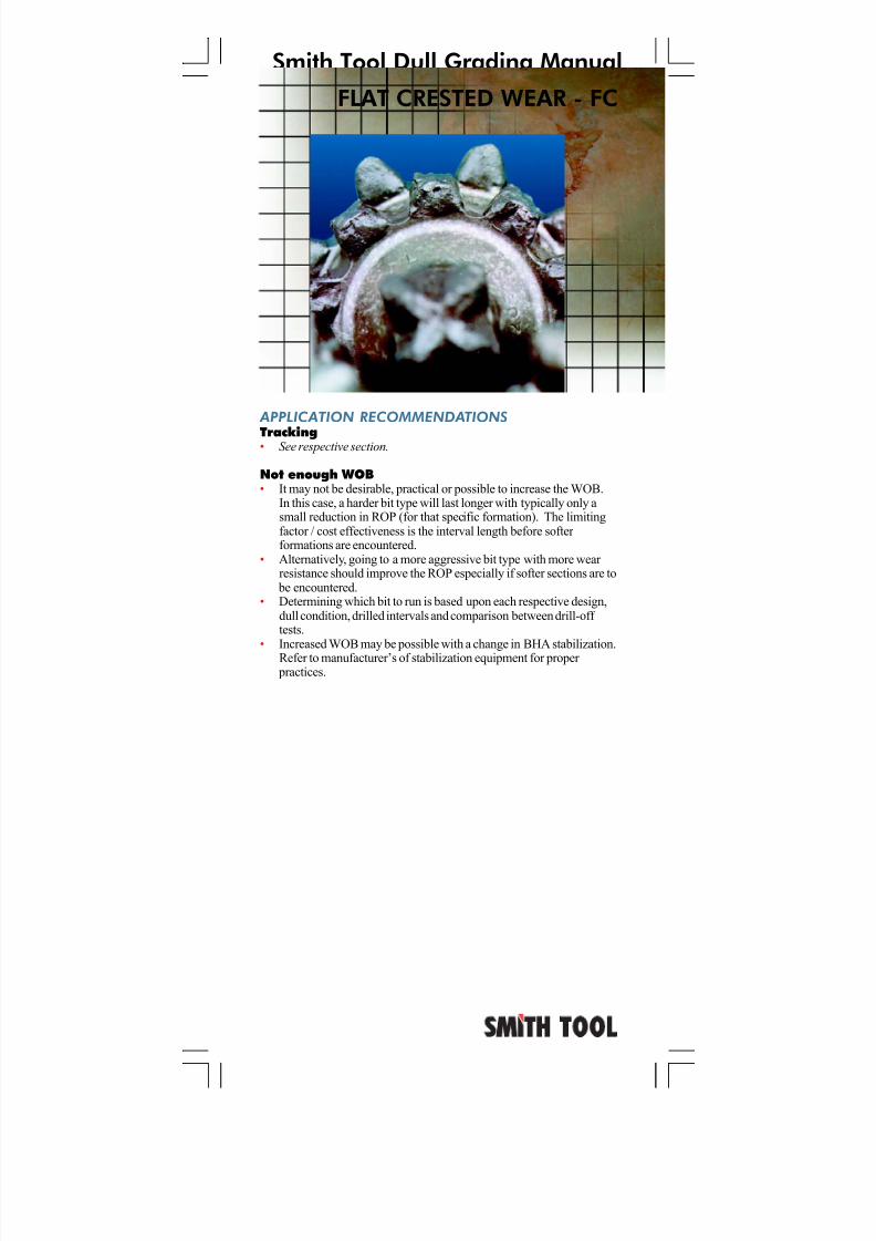
Not enough WOB• It may not be desirable, practical or possible to increase the WOB.In this case, a harder bit type will last longer with typically only asmall reduction in ROP (for that specific formation). The limitingfactor / cost effectiveness is interval length before softer formationsare encountered.
• Alternatively, going to a more aggressive bit type with more wear resistance should improve the ROP especially if softer sections are to
be encountered.• Determining which bit to run is based upon each respective dull
condition, drilled intervals and comparison between drill-off tests.• Increased WOB may be possible with a change in BHA stabiliza-
tion. Refer to manufacturer’s of stabilization equipment for proper practices.
Formation / improper bit selection• For abrasive formations, select bits with less offset, and/or greater
tooth count, and/or a more wear resistant cutting structure.• Bits with multiple cutting elements which share the gauge cutting
function should wear less due to kerf reduction.• Cutting structures with diamond enhanced cutting elements can
eliminate wear in many applications.
Excessive RPM for application and specific bit type• Use proper RPM for formation.• For abrasive formations, select bits with less offset, and/or greater
gauge tooth count, and/or a more wear resistant cutting structure.
Excessive hours for application and specific bit type• Reduce rotating hours or select a more durable cutting structure.
Inadequate hydraulics• Increased hydraulic energy is needed to address this condition.
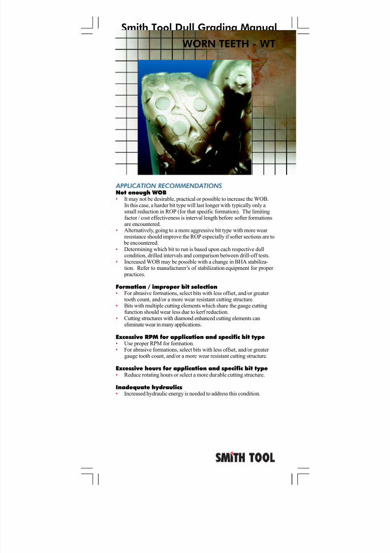
WORN TEETH - WT
7/11/2019 Bit Dull Grade
http://slidepdf.com/reader/full/bit-dull-grade 44/99
Smith Tool Dull Grading Manual
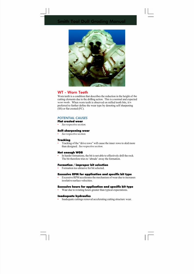
WT - Worn TeethWorn teeth is a condition that describes the reduction in the height of thecutting elements due to the drilling action. This is a normal and expectedwear mode. When worn teeth is observed on milled tooth bits, it is
preferred to further define the wear type by denoting self sharpening(SS) or flat crested (FC).
POTENTIAL CAUSES
Flat crested wear• See respective section.
Self-sharpening wear• See respective section.
Tracking
• Tracking of the “drive rows” will cause the inner rows to skid morethan designed. See respective section.
Not enough WOB• In harder formations, the bit is not able to effectively drill the rock.
The bit therefore tries to ‘abrade’ away the formation.
Formation / improper bit selection• Formation too abrasive for bit selected.
Excessive RPM for application and specific bit type• Excessive RPM accelerates the mechanism of wear due to increases
in relative surface velocities.
Excessive hours for application and specific bit type• Wear due to rotating hours greater than typical expectations.
Inadequate hydraulics• Inadequate cuttings removal accelerating cutting structure wear.
7/11/2019 Bit Dull Grade
http://slidepdf.com/reader/full/bit-dull-grade 45/99
Smith Tool Dull Grading Manual
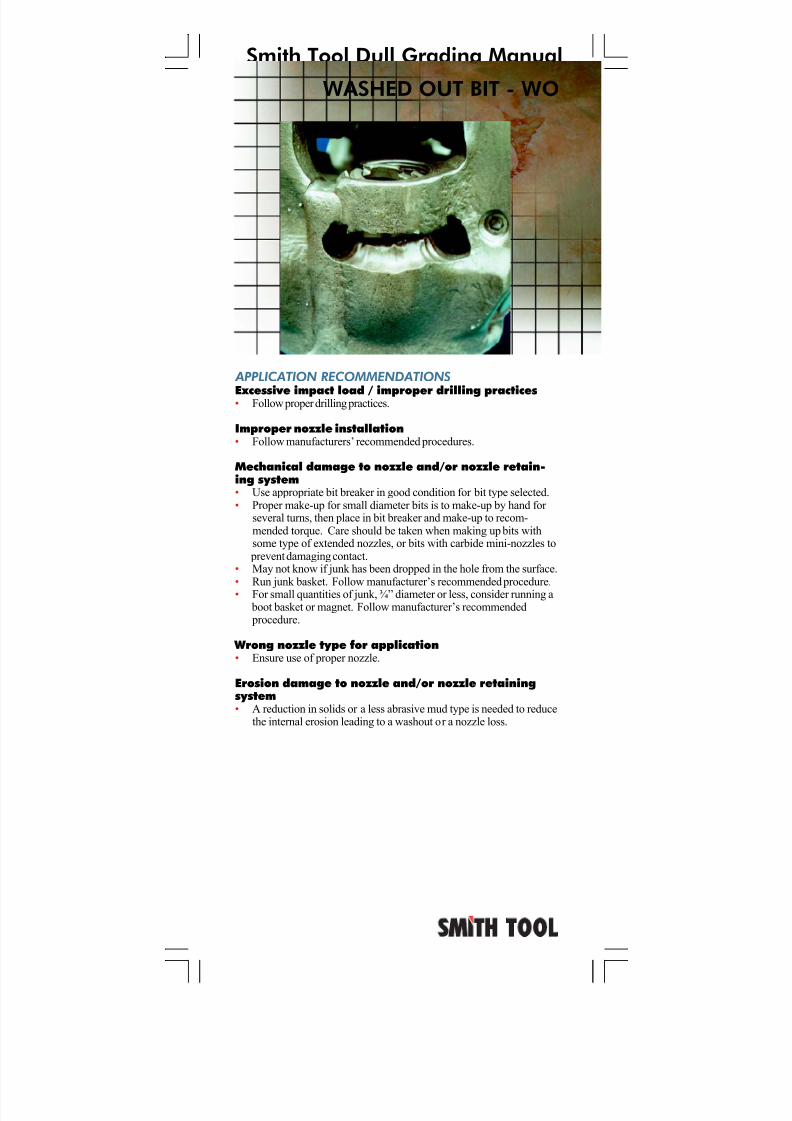
WASHED OUT BIT - WO
APPLICATION RECOMMENDATIONS
Excessive impact load / improper drilling practices• Follow proper drilling practices.
Improper nozzle installation• Follow manufacturers’ recommended procedures.
Mechanical damage to nozzle and/or nozzle retain-ing system• Use appropriate bit breaker in good condition for bit type selected.• Proper make-up for small diameter bits is to make-up by hand for
several turns, then place in bit breaker and make-up to recom-mended torque. Care should be taken when making up bits withsome type of extended nozzles, or bits with carbide mini-nozzles to
prevent damaging contact.• May not know if junk has been dropped in the hole from the surface.• Run junk basket. Follow manufacturer’s recommended procedure.• For small quantities of junk, ¾” diameter or less, consider running a
boot basket or magnet. Follow manufacturer’s recommended procedure.
Wrong nozzle type for application• Ensure use of proper nozzle.
Erosion damage to nozzle and/or nozzle retainingsystem• A reduction in solids or a less abrasive mud type is needed to reduce
the internal erosion leading to a washout or a nozzle loss.
7/11/2019 Bit Dull Grade
http://slidepdf.com/reader/full/bit-dull-grade 46/99
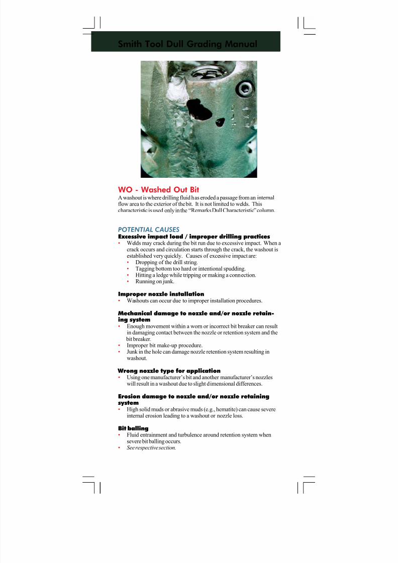
Smith Tool Dull Grading Manual
WO - Washed Out BitA washout is where drilling fluid has eroded a passage from an internalflow area to the exterior of the bit. It is not limited to welds. Thischaracteristic is used only in the “Remarks Dull Characteristic” column.
POTENTIAL CAUSES
Excessive impact load / improper drilling practices• Welds may crack during the bit run due to excessive impact. When a
crack occurs and circulation starts through the crack, the washout isestablished very quickly. Causes of excessive impact are:• Dropping of the drill string.• Tagging bottom too hard or intentional spudding.• Hitting a ledge while tripping or making a connection.• Running on junk.
Improper nozzle installation• Washouts can occur due to improper installation procedures.
Mechanical damage to nozzle and/or nozzle retain-ing system• Enough movement within a worn or incorrect bit breaker can result
in damaging contact between the nozzle or retention system and the bit breaker.
• Improper bit make-up procedure.• Junk in the hole can damage nozzle retention system resulting in
washout.
Wrong nozzle type for application• Using one manufacturer’s bit and another manufacturer’s nozzles
will result in a washout due to slight dimensional differences.
Erosion damage to nozzle and/or nozzle retainingsystem• High solid muds or abrasive muds (e.g., hematite) can cause severe
internal erosion leading to a washout or nozzle loss.
Bit balling• Fluid entrainment and turbulence around retention system when
severe bit balling occurs.• See respective section.
7/11/2019 Bit Dull Grade
http://slidepdf.com/reader/full/bit-dull-grade 47/99
Smith Tool Dull Grading Manual
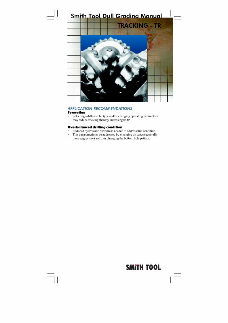
APPLICATION RECOMMENDATIONS
Formation• Selecting a different bit type and/or changing operating parametersmay reduce tracking thereby increasing ROP.
Overbalanced drilling condition• Reduced hydrostatic pressure is needed to address this condition.• This can sometimes be addressed by changing bit types (generally
more aggressive) and thus changing the bottom hole pattern.
TRACKING - TR
7/11/2019 Bit Dull Grade
http://slidepdf.com/reader/full/bit-dull-grade 48/99
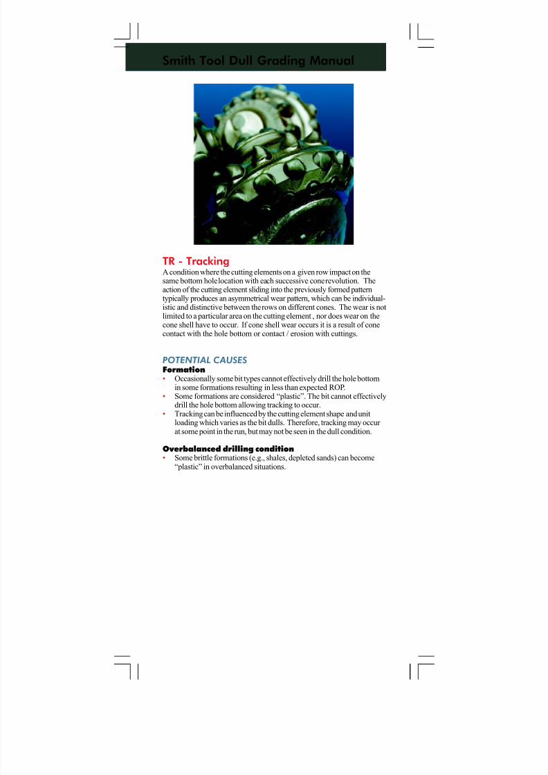
Smith Tool Dull Grading Manual
TR - TrackingA condition where the cutting elements on a given row impact on thesame bottom hole location with each successive cone revolution. Theaction of the cutting element sliding into the previously formed patterntypically produces an asymmetrical wear pattern, which can be individual-istic and distinctive between the rows on different cones. The wear is notlimited to a particular area on the cutting element , nor does wear on thecone shell have to occur. If cone shell wear occurs it is a result of conecontact with the hole bottom or contact / erosion with cuttings.
POTENTIAL CAUSES
Formation• Occasionally some bit types cannot effectively drill the hole bottom
in some formations resulting in less than expected ROP.• Some formations are considered “plastic”. The bit cannot effectively
drill the hole bottom allowing tracking to occur.• Tracking can be influenced by the cutting element shape and unitloading which varies as the bit dulls. Therefore, tracking may occur at some point in the run, but may not be seen in the dull condition.
Overbalanced drilling condition• Some brittle formations (e.g., shales, depleted sands) can become
“plastic” in overbalanced situations.
7/11/2019 Bit Dull Grade
http://slidepdf.com/reader/full/bit-dull-grade 49/99
Smith Tool Dull Grading Manual
SELF SHARPENING WEAR - SS
7/11/2019 Bit Dull Grade
http://slidepdf.com/reader/full/bit-dull-grade 50/99
Smith Tool Dull Grading Manual
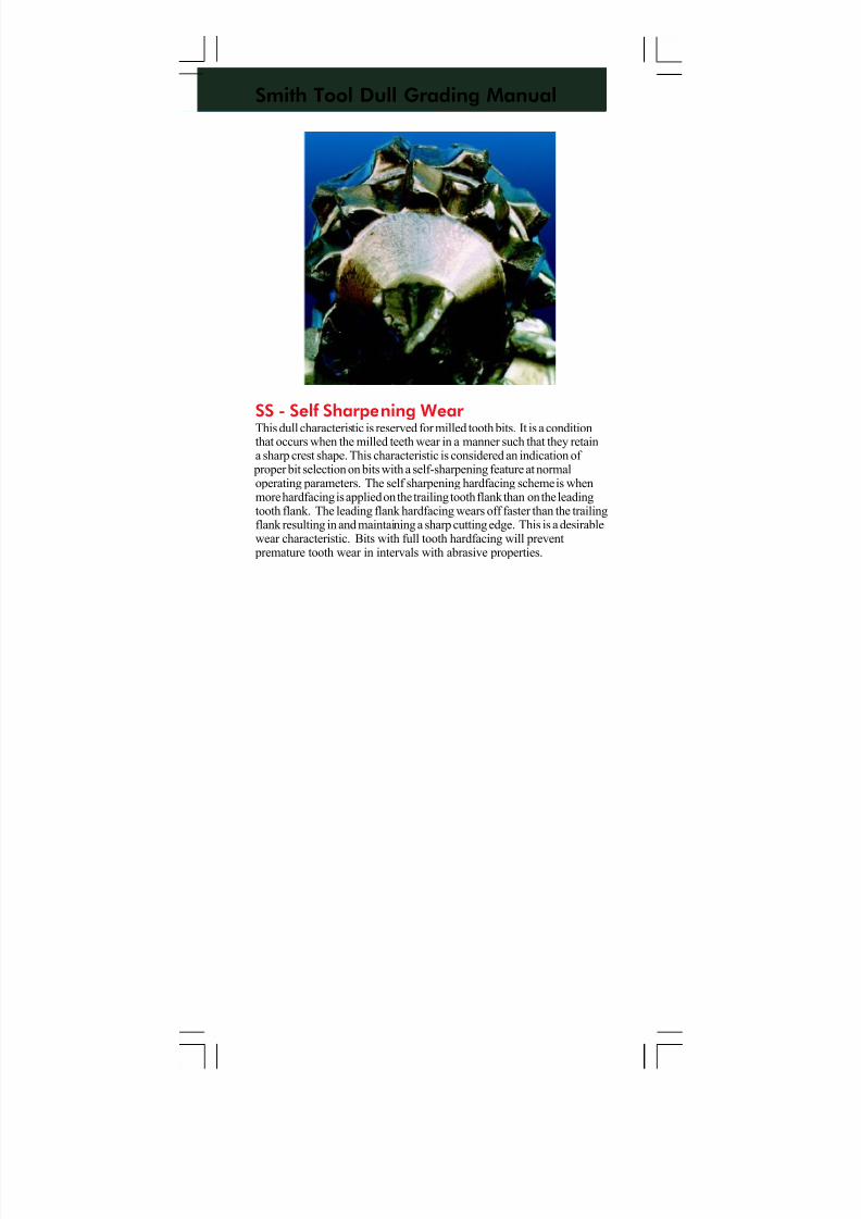
SS - Self Sharpening Wear This dull characteristic is reserved for milled tooth bits. It is a conditionthat occurs when the milled teeth wear in a manner such that they retaina sharp crest shape. This characteristic is considered an indication of
proper bit selection on bits with a self-sharpening feature at normaloperating parameters. The self sharpening hardfacing scheme is whenmore hardfacing is applied on the trailing tooth flank than on the leadingtooth flank. The leading flank hardfacing wears off faster than the trailingflank resulting in and maintaining a sharp cutting edge. This is a desirablewear characteristic. Bits with full tooth hardfacing will prevent
premature tooth wear in intervals with abrasive properties.
7/11/2019 Bit Dull Grade
http://slidepdf.com/reader/full/bit-dull-grade 51/99
Smith Tool Dull Grading Manual
APPLICATION RECOMMENDATIONS
Run on junk • May not know if junk has been dropped in the hole from the surface.• Run junk basket. Follow manufacturer’s recommended procedure.• For small quantities of parts, ¾” diameter or less, consider running a
boot basket or magnet. Follow manufacturer’s recommended procedure.
Reaming undergauge hole• Ream using very light WOB and low RPM. A hole in a slightly
undergauge condition requires a lesser amount of WOB than a holein a greater undergauge condition. For example, a hole 1/16”undergauge requires less WOB in order to not damage the bit than ahole 1/2” undergauge.
• If the life of a roller cone bit is limited due to immediate gauge wear when following a fixed cutter bit, select a bit with a more robustgauge structure and/or with less offset.
Deviated holes• Select bits with shirttail protection features and/or with stabilization
features.
Inadequate and/or poor hydraulics• Increased hydraulic energy is needed to address this condition.• Mini-extended nozzles can improve bottom hole cleaning by
extending the nozzle exit closer to the hole bottom improvingimpinging jet velocity and pressure profile.
• Crossflow and asymmetrical nozzle configurations can provide better bottom hole cleaning.
• Select bits with shirttail protection features.
Inadequate stabilization
• Select bits with stabilization features.• Parallel misalignment is typically due to using drill collars too small
in relation to the hole size. Refer to manufacturers of stabilizationequipment for proper practices.
SHIRTTAIL DAMAGE - SD
7/11/2019 Bit Dull Grade
http://slidepdf.com/reader/full/bit-dull-grade 52/99
Smith Tool Dull Grading Manual
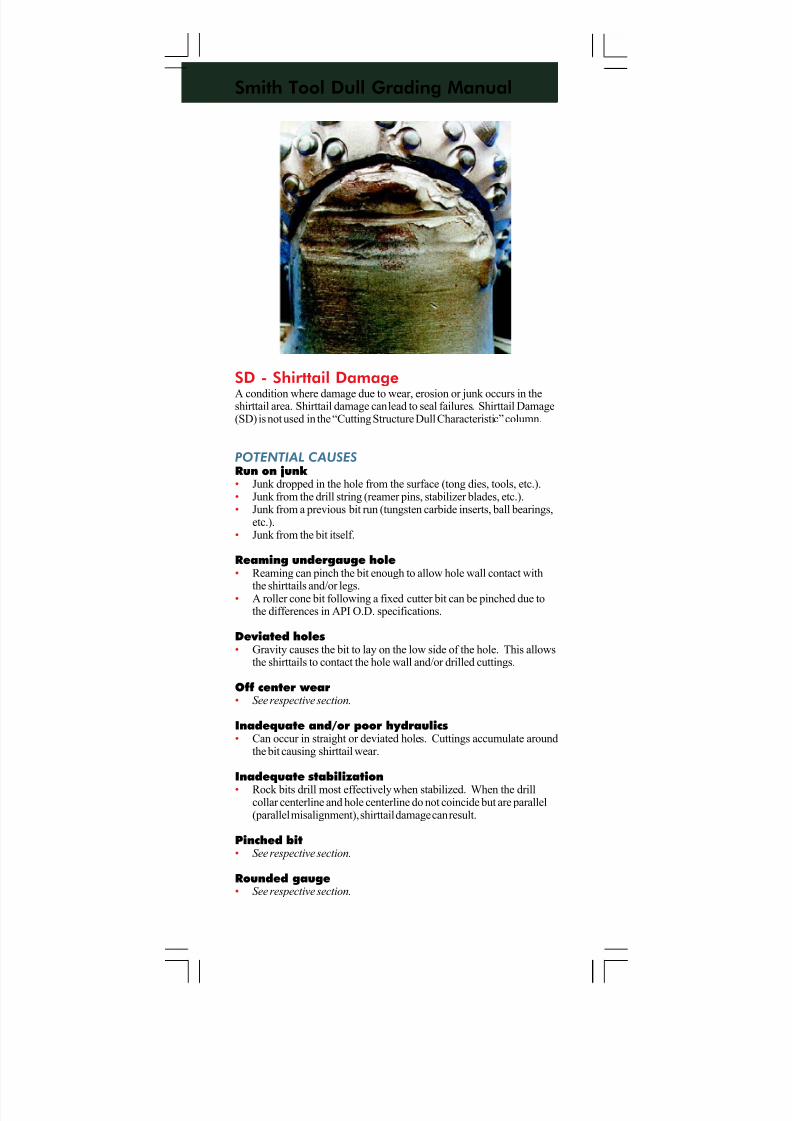
SD - Shirttail DamageA condition where damage due to wear, erosion or junk occurs in theshirttail area. Shirttail damage can lead to seal failures. Shirttail Damage(SD) is not used in the “Cutting Structure Dull Characteristic” column.
POTENTIAL CAUSES
Run on junk • Junk dropped in the hole from the surface (tong dies, tools, etc.).• Junk from the drill string (reamer pins, stabilizer blades, etc.).• Junk from a previous bit run (tungsten carbide inserts, ball bearings,
etc.).• Junk from the bit itself.
Reaming undergauge hole• Reaming can pinch the bit enough to allow hole wall contact with
the shirttails and/or legs.• A roller cone bit following a fixed cutter bit can be pinched due tothe differences in API O.D. specifications.
Deviated holes• Gravity causes the bit to lay on the low side of the hole. This allows
the shirttails to contact the hole wall and/or drilled cuttings.
Off center wear• See respective section.
Inadequate and/or poor hydraulics• Can occur in straight or deviated holes. Cuttings accumulate around
the bit causing shirttail wear.
Inadequate stabilization• Rock bits drill most effectively when stabilized. When the drill
collar centerline and hole centerline do not coincide but are parallel(parallel misalignment), shirttail damage can result.
Pinched bit• See respective section.
Rounded gauge• See respective section.
7/11/2019 Bit Dull Grade
http://slidepdf.com/reader/full/bit-dull-grade 53/99
Smith Tool Dull Grading Manual
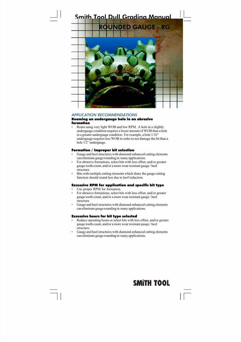
ROUNDED GAUGE - RG
APPLICATION RECOMMENDATIONS
Reaming an undergauge hole in an abrasiveformation• Ream using very light WOB and low RPM. A hole in a slightly
undergauge condition requires a lesser amount of WOB than a holein a greater undergauge condition. For example, a hole 1/16”undergauge requires less WOB in order to not damage the bit than ahole 1/2” undergauge.
Formation / improper bit selection• Gauge and heel structures with diamond enhanced cutting elements
can eliminate gauge rounding in many applications.• For abrasive formations, select bits with less offset, and/or greater
gauge tooth count, and/or a more wear resistant gauge / heelstructure.
• Bits with multiple cutting elements which share the gauge cuttingfunction should round less due to kerf reduction.
Excessive RPM for application and specific bit type• Use proper RPM for formation.• For abrasive formations, select bits with less offset, and/or greater
gauge tooth count, and/or a more wear resistant gauge / heelstructure.
• Gauge and heel structures with diamond enhanced cutting elementscan eliminate gauge rounding in many applications.
Excessive hours for bit type selected• Reduce operating hours or select bits with less offset, and/or greater
gauge tooth count, and/or a more wear resistant gauge / heelstructure.
• Gauge and heel structures with diamond enhanced cutting elementscan eliminate gauge rounding in many applications.
7/11/2019 Bit Dull Grade
http://slidepdf.com/reader/full/bit-dull-grade 54/99
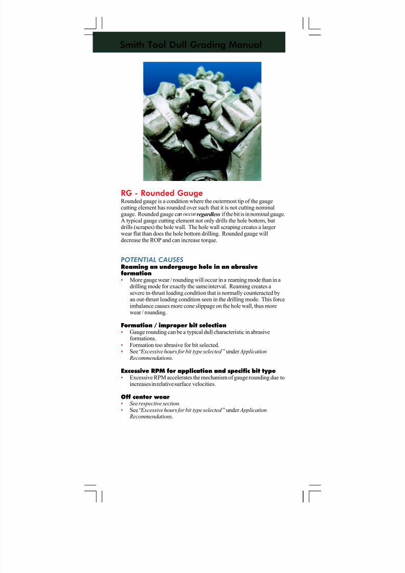
Smith Tool Dull Grading Manual
RG - Rounded GaugeRounded gauge is a condition where the outermost tip of the gaugecutting element has rounded over such that it is not cutting nominalgauge. Rounded gauge can occur regardless if the bit is in nominal gauge.A typical gauge cutting element not only drills the hole bottom, butdrills (scrapes) the hole wall. The hole wall scraping creates a larger wear flat than does the hole bottom drilling. Rounded gauge willdecrease the ROP and can increase torque.
POTENTIAL CAUSES
Reaming an undergauge hole in an abrasiveformation• More gauge wear / rounding will occur in a reaming mode than in a
drilling mode for exactly the same interval. Reaming creates asevere in-thrust loading condition that is normally counteracted by
an out-thrust loading condition seen in the drilling mode. This forceimbalance causes more cone slippage on the hole wall, thus morewear / rounding.
Formation / improper bit selection• Gauge rounding can be a typical dull characteristic in abrasive
formations.• Formation too abrasive for bit selected.• See “ Excessive hours for bit type selected ” under Application
Recommendations.
Excessive RPM for application and specific bit type• Excessive RPM accelerates the mechanism of gauge rounding due to
increases in relative surface velocities.
Off center wear• See respective section.• See “ Excessive hours for bit type selected ” under Application
Recommendations.
7/11/2019 Bit Dull Grade
http://slidepdf.com/reader/full/bit-dull-grade 55/99
Smith Tool Dull Grading Manual
APPLICATION RECOMMENDATIONS
Improper drilling practices• Use nozzle strainers when tripping in.• Follow proper drilling practices.
Pumped foreign material• If known conditions exist, use pipe screens.• For lost circulation material, an increase in the nozzle size or a
change in the nozzle arrangement is needed to address thiscondition.
Formation plugging• Run float to prevent reverse circulation during connections.• Small nozzles are more susceptible to plugging. An increase in the
nozzle size or a change in the nozzle arrangement is needed toaddress this condition.
• Asymmetrical nozzle arrangements may be more susceptible to plugging than standard two or three nozzle arrangements.
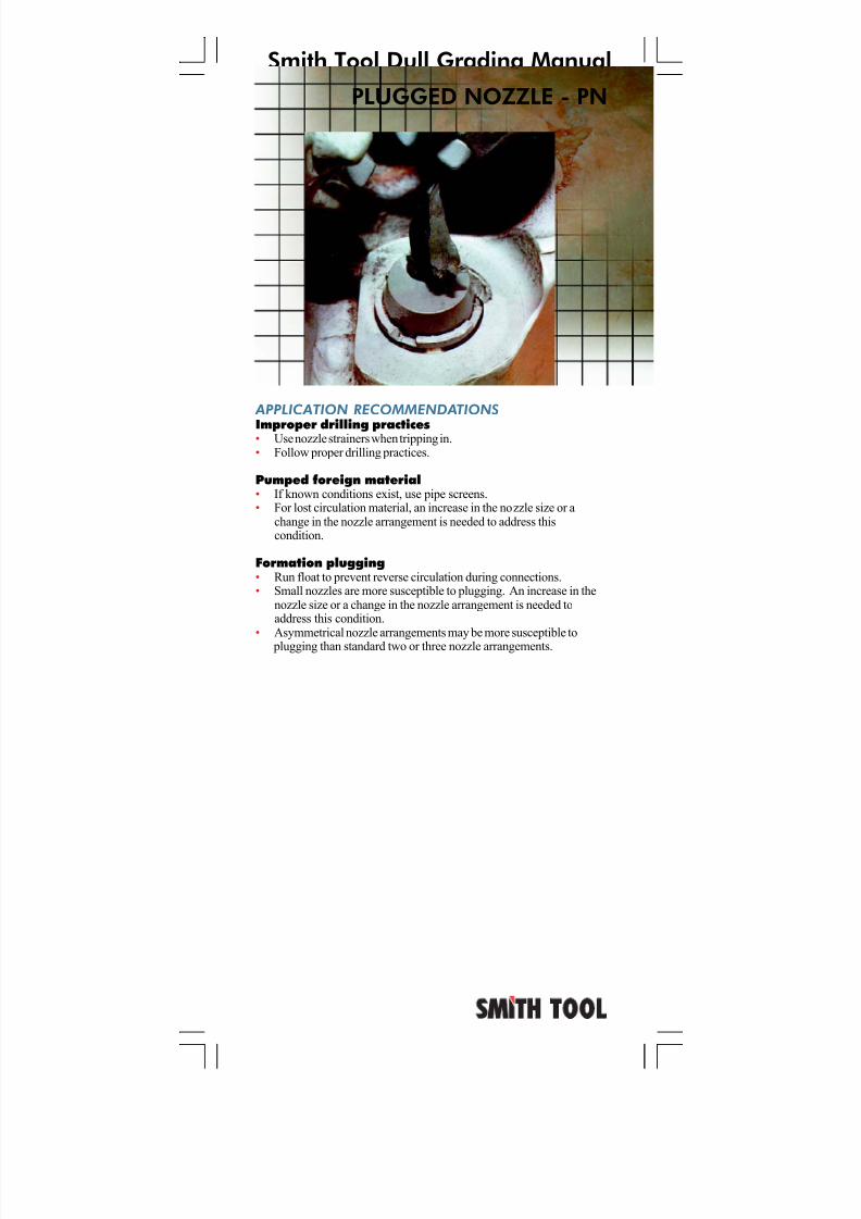
PLUGGED NOZZLE - PN
7/11/2019 Bit Dull Grade
http://slidepdf.com/reader/full/bit-dull-grade 56/99
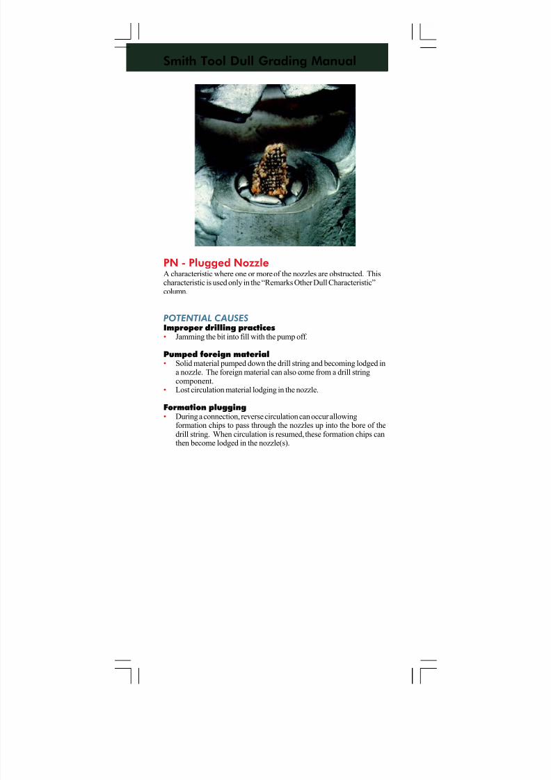
Smith Tool Dull Grading Manual
PN - Plugged NozzleA characteristic where one or more of the nozzles are obstructed. Thischaracteristic is used only in the “Remarks Other Dull Characteristic”column.
POTENTIAL CAUSES
Improper drilling practices• Jamming the bit into fill with the pump off.
Pumped foreign material• Solid material pumped down the drill string and becoming lodged in
a nozzle. The foreign material can also come from a drill stringcomponent.
• Lost circulation material lodging in the nozzle.
Formation plugging• During a connection, reverse circulation can occur allowingformation chips to pass through the nozzles up into the bore of thedrill string. When circulation is resumed, these formation chips canthen become lodged in the nozzle(s).
7/11/2019 Bit Dull Grade
http://slidepdf.com/reader/full/bit-dull-grade 57/99
Smith Tool Dull Grading Manual
APPLICATION RECOMMENDATIONS
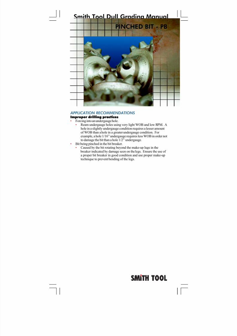
Improper drilling practices• Forcing into an undergauge hole.• Ream undergauge holes using very light WOB and low RPM. A
hole in a slightly undergauge condition requires a lesser amountof WOB than a hole in a greater undergauge condition. For example, a hole 1/16” undergauge requires less WOB in order notto damage the bit than a hole 1/2” undergauge.
• Bit being pinched in the bit breaker.• Caused by the bit rotating beyond the make-up lugs in the
breaker indicated by damage seen on the legs. Ensure the use of a proper bit breaker in good condition and use proper make-uptechnique to prevent bending of the legs.
PINCHED BIT - PB
7/11/2019 Bit Dull Grade
http://slidepdf.com/reader/full/bit-dull-grade 58/99
Smith Tool Dull Grading Manual
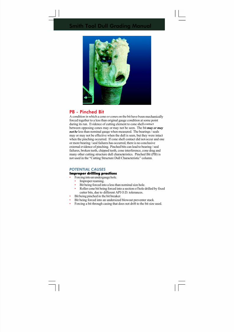
PB - Pinched BitA condition in which a cone or cones on the bit have been mechanicallyforced together to a less than original gauge condition at some pointduring its run. Evidence of cutting element to cone shell contact
between opposing cones may or may not be seen. The bit may or maynot be less than nominal gauge when measured. The bearings / sealsmay or may not be effective when the dull is seen, but they were intactwhen the pinching occurred. If cone shell contact did not occur and oneor more bearing / seal failures has occurred, there is no conclusiveexternal evidence of pinching. Pinched bits can lead to bearing / sealfailures, broken teeth, chipped teeth, cone interference, cone drag andmany other cutting structure dull characteristics. Pinched Bit (PB) isnot used in the “Cutting Structure Dull Characteristic” column.
POTENTIAL CAUSES
Improper drilling practices• Forcing into an undergauge hole.• Improper reaming.• Bit being forced into a less than nominal size hole.• Roller cone bit being forced into a section of hole drilled by fixed
cutter bits, due to different API O.D. tolerances.• Bit being pinched in the bit breaker.• Bit being forced into an undersized blowout preventer stack.• Forcing a bit through casing that does not drift to the bit size used.
7/11/2019 Bit Dull Grade
http://slidepdf.com/reader/full/bit-dull-grade 59/99
Smith Tool Dull Grading Manual
OFF CENTER WEAR - OC
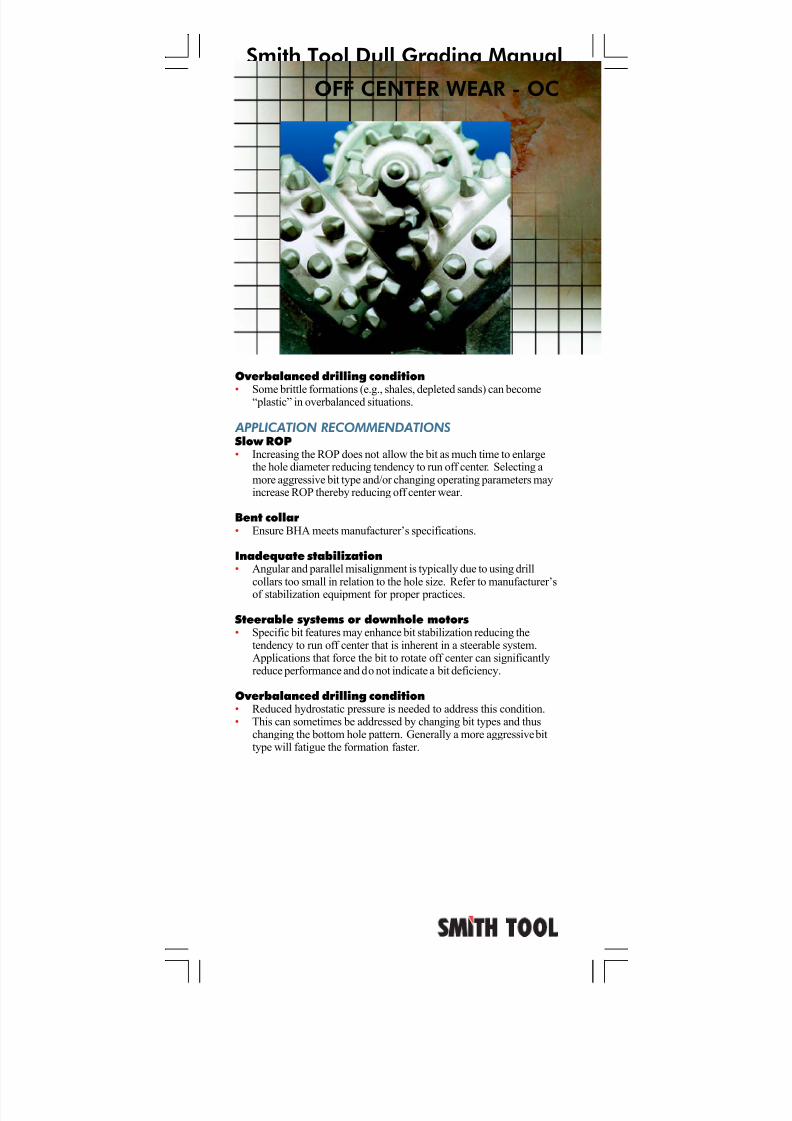
Overbalanced drilling condition
• Some brittle formations (e.g., shales, depleted sands) can become“plastic” in overbalanced situations.
APPLICATION RECOMMENDATIONS
Slow ROP• Increasing the ROP does not allow the bit as much time to enlarge
the hole diameter reducing tendency to run off center. Selecting amore aggressive bit type and/or changing operating parameters mayincrease ROP thereby reducing off center wear.
Bent collar• Ensure BHA meets manufacturer’s specifications.
Inadequate stabilization• Angular and parallel misalignment is typically due to using drill
collars too small in relation to the hole size. Refer to manufacturer’sof stabilization equipment for proper practices.
Steerable systems or downhole motors• Specific bit features may enhance bit stabilization reducing the
tendency to run off center that is inherent in a steerable system.Applications that force the bit to rotate off center can significantlyreduce performance and do not indicate a bit deficiency.
Overbalanced drilling condition• Reduced hydrostatic pressure is needed to address this condition.• This can sometimes be addressed by changing bit types and thus
changing the bottom hole pattern. Generally a more aggressive bittype will fatigue the formation faster.
7/11/2019 Bit Dull Grade
http://slidepdf.com/reader/full/bit-dull-grade 60/99
Smith Tool Dull Grading Manual
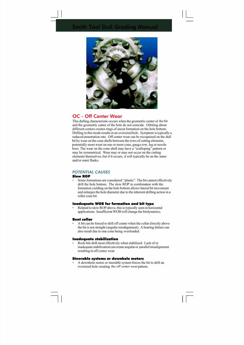
OC - Off Center Wear This dulling characteristic occurs when the geometric center of the bitand the geometric center of the hole do not coincide. Orbiting aboutdifferent centers creates rings of uncut formation on the hole bottom.Drilling in this mode results in an oversized hole. Symptom is typically areduced penetration rate. Off center wear can be recognized on the dull
bit by wear on the cone shells between the rows of cutting elements, potentially more wear on one or more cone, gauge row, leg or nozzle boss. The wear on the cone shell may have a “scalloping” pattern or may be symmetrical. Wear may or may not occur on the cuttingelements themselves, but if it occurs, it will typically be on the inner and/or outer flanks.
POTENTIAL CAUSES
Slow ROP
• Some formations are considered “plastic”. The bit cannot effectivelydrill the hole bottom. The slow ROP in combination with theformation yielding on the hole bottom allows lateral bit movementand enlarges the hole diameter due to the inherent drilling action in aroller cone bit.
Inadequate WOB for formation and bit type• Related to slow ROP above, this is typically seen in horizontal
applications. Insufficient WOB will change the bit dynamics.
Bent collar• A bit can be forced to drill off center when the collar directly above
the bit is not straight (angular misalignment). A bearing failure canalso result due to one cone being overloaded.
Inadequate stabilization• Rock bits drill most effectively when stabilized. Lack of or
inadequate stabilization can create angular or parallel misalignmentresulting in off center wear.
Steerable systems or downhole motors• A downhole motor or steerable system forces the bit to drill an
oversized hole creating the off center wear pattern.
7/11/2019 Bit Dull Grade
http://slidepdf.com/reader/full/bit-dull-grade 61/99
Smith Tool Dull Grading Manual
LOST TEETH - LT
APPLICATION RECOMMENDATIONS
Excessive WOB for particular type• Run proper WOB for specific bit type to achieve average run hours.
Excessive hours for particular type• Reduce operating hours or select a more durable bit type.
Drilling environment• Follow recommended drilling fluid guidelines to address these
conditions.
Overbalanced drilling condition• Reduced hydrostatic pressure is needed to address this condition.
7/11/2019 Bit Dull Grade
http://slidepdf.com/reader/full/bit-dull-grade 62/99
Smith Tool Dull Grading Manual
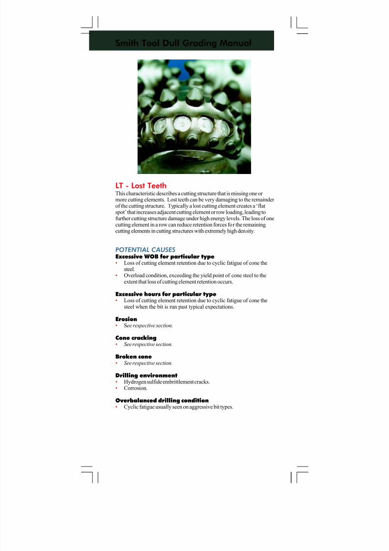
LT - Lost TeethThis characteristic describes a cutting structure that is missing one or more cutting elements. Lost teeth can be very damaging to the remainder of the cutting structure. Typically a lost cutting element creates a ‘flatspot’ that increases adjacent cutting element or row loading, leading tofurther cutting structure damage under high energy levels. The loss of onecutting element in a row can reduce retention forces for the remainingcutting elements in cutting structures with extremely high density.
POTENTIAL CAUSES
Excessive WOB for particular type• Loss of cutting element retention due to cyclic fatigue of cone the
steel.• Overload condition, exceeding the yield point of cone steel to the
extent that loss of cutting element retention occurs.
Excessive hours for particular type• Loss of cutting element retention due to cyclic fatigue of cone the
steel when the bit is run past typical expectations.
Erosion• See respective section.
Cone cracking• See respective section.
Broken cone• See respective section.
Drilling environment• Hydrogen sulfide embrittlement cracks.
• Corrosion.
Overbalanced drilling condition• Cyclic fatigue usually seen on aggressive bit types.
7/11/2019 Bit Dull Grade
http://slidepdf.com/reader/full/bit-dull-grade 63/99
Smith Tool Dull Grading Manual
LOST NOZZLE - LN
APPLICATION RECOMMENDATIONS
Improper nozzle installation• Follow manufacturer’s recommended procedures.
Mechanical damage to nozzle and/or nozzle retain-ing system• Use appropriate bit breaker in good condition for bit type selected.• Proper make-up for small diameter bits is to make-up by hand for
several turns, then place in the bit breaker and make-up to therecommended torque. Care should be taken when making up bitswith extended nozzles, or bits with carbide mini-nozzles to preventdamaging contact.
• May not know if junk has been dropped in the hole from the surface.• Run junk basket. Follow manufacturer’s recommended procedure.• For small quantities of parts, ¾” diameter or less, consider running a
boot basket or magnet. Follow manufacturer’s recommended procedure.
Wrong nozzle type for application• Ensure use of proper nozzle.
Erosion damage to nozzle and/or nozzle retainingsystem• Solids reduction is needed to address this condition.
7/11/2019 Bit Dull Grade
http://slidepdf.com/reader/full/bit-dull-grade 64/99
Smith Tool Dull Grading Manual
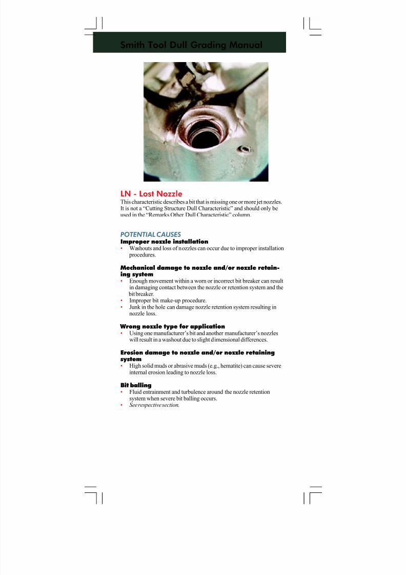
LN - Lost NozzleThis characteristic describes a bit that is missing one or more jet nozzles.It is not a “Cutting Structure Dull Characteristic” and should only beused in the “Remarks Other Dull Characteristic” column.
POTENTIAL CAUSES
Improper nozzle installation• Washouts and loss of nozzles can occur due to improper installation
procedures.
Mechanical damage to nozzle and/or nozzle retain-ing system• Enough movement within a worn or incorrect bit breaker can result
in damaging contact between the nozzle or retention system and the bit breaker.
• Improper bit make-up procedure.• Junk in the hole can damage nozzle retention system resulting innozzle loss.
Wrong nozzle type for application• Using one manufacturer’s bit and another manufacturer’s nozzles
will result in a washout due to slight dimensional differences.
Erosion damage to nozzle and/or nozzle retainingsystem• High solid muds or abrasive muds (e.g., hematite) can cause severe
internal erosion leading to nozzle loss.
Bit balling• Fluid entrainment and turbulence around the nozzle retention
system when severe bit balling occurs.
• See respective section.
7/11/2019 Bit Dull Grade
http://slidepdf.com/reader/full/bit-dull-grade 65/99
Smith Tool Dull Grading Manual
APPLICATION RECOMMENDATIONS
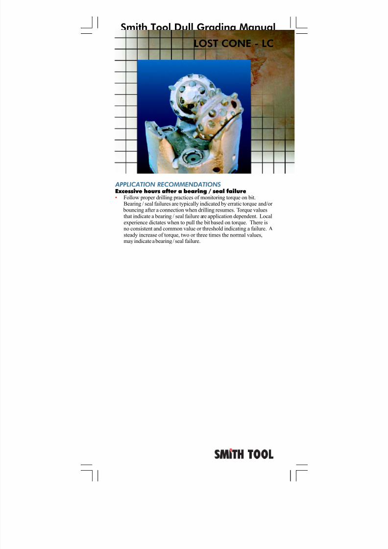
Excessive hours after a bearing / seal failure• Follow proper drilling practices of monitoring torque on bit.Bearing / seal failures are typically indicated by erratic torque and/or
bouncing after a connection when drilling resumes. Torque valuesthat indicate a bearing / seal failure are application dependent. Localexperience dictates when to pull the bit based on torque. There isno consistent and common value or threshold indicating a failure. Asteady increase of torque, two or three times the normal values,may indicate a bearing / seal failure.
LOST CONE - LC
7/11/2019 Bit Dull Grade
http://slidepdf.com/reader/full/bit-dull-grade 66/99
Smith Tool Dull Grading Manual
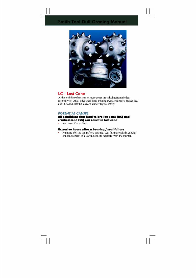
LC - Lost ConeA bit condition when one or more cones are missing from the legassembly(s). Also, since there is no existing IADC code for a broken leg,use LC to indicate the loss of a cutter / leg assembly.
POTENTIAL CAUSES
All conditions that lead to broken cone (BC) andcracked cone (CC) can result in lost cone• See respective sections.
Excessive hours after a bearing / seal failure• Running a bit too long after a bearing / seal failure results in enough
cone movement to allow the cone to separate from the journal.
7/11/2019 Bit Dull Grade
http://slidepdf.com/reader/full/bit-dull-grade 67/99
Smith Tool Dull Grading Manual
JUNK DAMAGE - JD
APPLICATION RECOMMENDATIONS
Run on junk • May not know if junk has been dropped in the hole from the surface.• Run junk basket. Follow manufacturer’s recommended procedure.• For small quantities of parts, ¾” diameter or less, consider running a
boot basket or magnet. Follow manufacturer’s recommended procedure.
7/11/2019 Bit Dull Grade
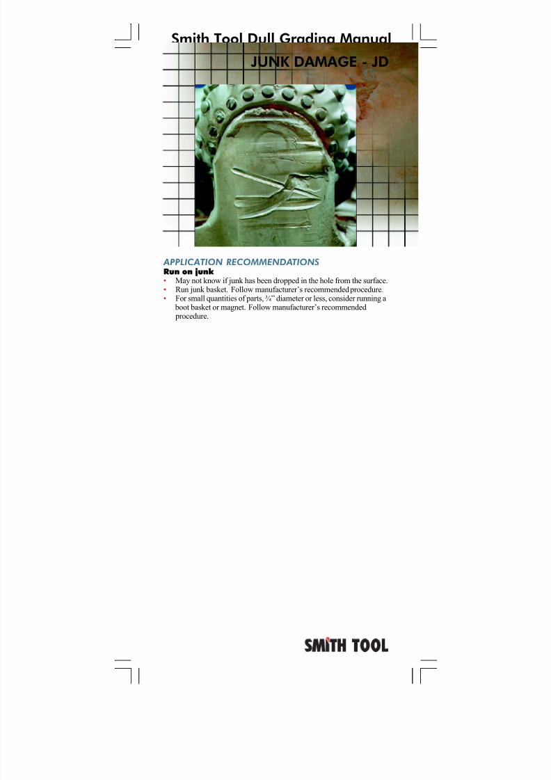
http://slidepdf.com/reader/full/bit-dull-grade 68/99
Smith Tool Dull Grading Manual
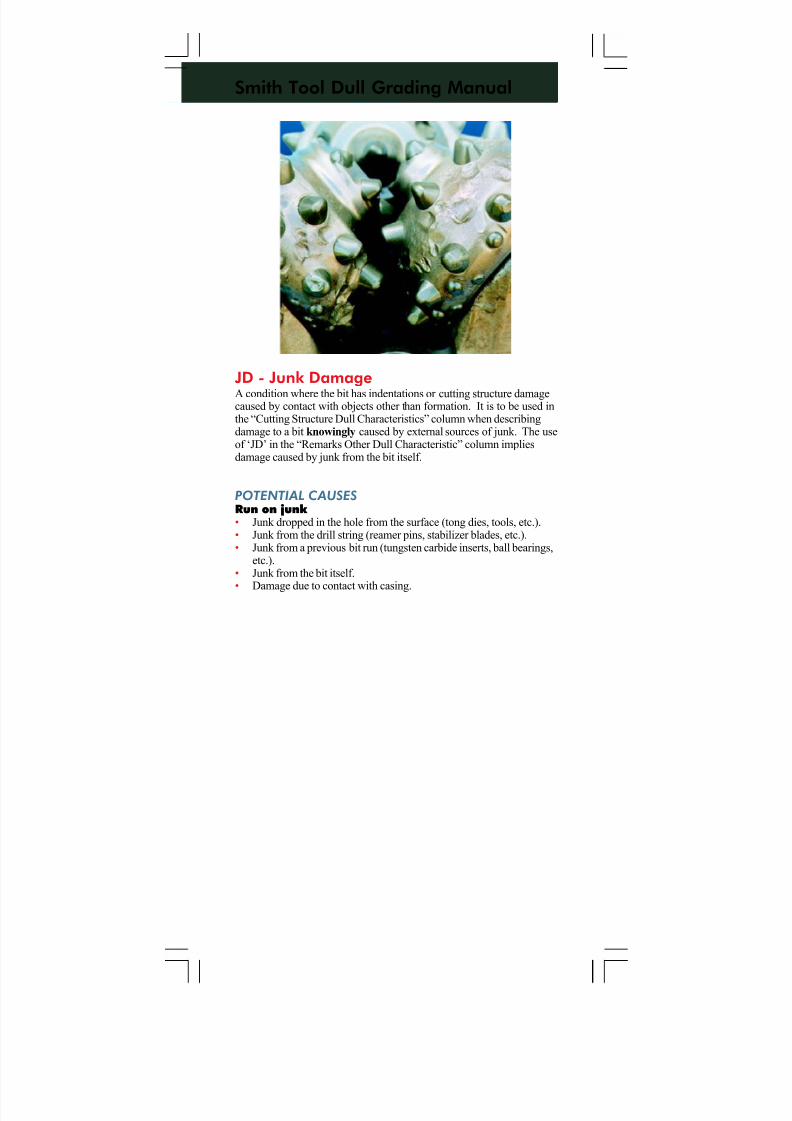
JD - Junk DamageA condition where the bit has indentations or cutting structure damagecaused by contact with objects other than formation. It is to be used inthe “Cutting Structure Dull Characteristics” column when describingdamage to a bit knowingly caused by external sources of junk. The useof ‘JD’ in the “Remarks Other Dull Characteristic” column impliesdamage caused by junk from the bit itself.
POTENTIAL CAUSES
Run on junk • Junk dropped in the hole from the surface (tong dies, tools, etc.).• Junk from the drill string (reamer pins, stabilizer blades, etc.).• Junk from a previous bit run (tungsten carbide inserts, ball bearings,
etc.).• Junk from the bit itself.
• Damage due to contact with casing.
7/11/2019 Bit Dull Grade
http://slidepdf.com/reader/full/bit-dull-grade 69/99
Smith Tool Dull Grading Manual
APPLICATION RECOMMENDATIONS
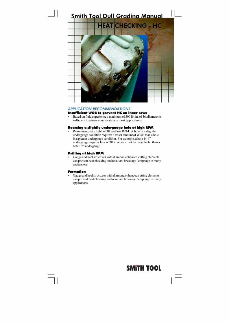
Insufficient WOB to prevent HC on inner rows• Based on field experience a minimum of 500 lb./in. of bit diameter issufficient to ensure cone rotation in most applications.
Reaming a slightly undergauge hole at high RPM• Ream using very light WOB and low RPM. A hole in a slightly
undergauge condition requires a lesser amount of WOB than a holein a greater undergauge condition. For example, a hole 1/16”undergauge requires less WOB in order to not damage the bit than ahole 1/2” undergauge.
Drilling at high RPM• Gauge and heel structures with diamond enhanced cutting elements
can prevent heat checking and resultant breakage / chippage in manyapplications.
Formation• Gauge and heel structures with diamond enhanced cutting elements
can prevent heat checking and resultant breakage / chippage in manyapplications.
HEAT CHECKING - HC
7/11/2019 Bit Dull Grade
http://slidepdf.com/reader/full/bit-dull-grade 70/99
Smith Tool Dull Grading Manual
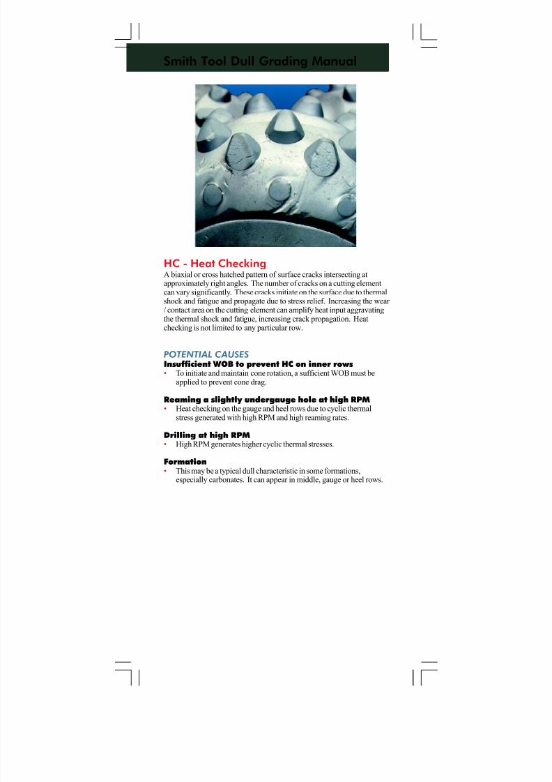
HC - Heat CheckingA biaxial or cross hatched pattern of surface cracks intersecting atapproximately right angles. The number of cracks on a cutting elementcan vary significantly. These cracks initiate on the surface due to thermalshock and fatigue and propagate due to stress relief. Increasing the wear / contact area on the cutting element can amplify heat input aggravatingthe thermal shock and fatigue, increasing crack propagation. Heatchecking is not limited to any particular row.
POTENTIAL CAUSES
Insufficient WOB to prevent HC on inner rows• To initiate and maintain cone rotation, a sufficient WOB must be
applied to prevent cone drag.
Reaming a slightly undergauge hole at high RPM
• Heat checking on the gauge and heel rows due to cyclic thermalstress generated with high RPM and high reaming rates.
Drilling at high RPM• High RPM generates higher cyclic thermal stresses.
Formation• This may be a typical dull characteristic in some formations,
especially carbonates. It can appear in middle, gauge or heel rows.
7/11/2019 Bit Dull Grade
http://slidepdf.com/reader/full/bit-dull-grade 71/99
Smith Tool Dull Grading Manual
APPLICATION RECOMMENDATIONS
Tracking• See respective section.
Not enough WOB• It may not be desirable, practical or possible to increase the WOB.
In this case, a harder bit type will last longer with typically only asmall reduction in ROP (for that specific formation). The limitingfactor / cost effectiveness is the interval length before softer formations are encountered.
• Alternatively, going to a more aggressive bit type with more wear resistance should improve the ROP especially if softer sections are to
be encountered.• Determining which bit to run is based upon each respective design,
dull condition, drilled intervals and comparison between drill-off tests.
• Increased WOB may be possible with a change in BHA stabilization.Refer to manufacturer’s of stabilization equipment for proper
practices.
FLAT CRESTED WEAR - FC
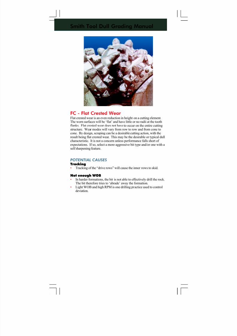
7/11/2019 Bit Dull Grade
http://slidepdf.com/reader/full/bit-dull-grade 72/99
Smith Tool Dull Grading Manual
FC - Flat Crested Wear Flat crested wear is an even reduction in height on a cutting element.The worn surfaces will be ‘flat’ and have little or no radii at the toothflanks. Flat crested wear does not have to occur on the entire cuttingstructure. Wear modes will vary from row to row and from cone tocone. By design, scraping can be a desirable cutting action, with theresult being flat crested wear. This may be the desirable or typical dullcharacteristic. It is not a concern unless performance falls short of expectations. If so, select a more aggressive bit type and/or one with aself sharpening feature.
POTENTIAL CAUSES
Tracking• Tracking of the “drive rows” will cause the inner rows to skid.
Not enough WOB• In harder formations, the bit is not able to effectively drill the rock.The bit therefore tries to ‘abrade’ away the formation.
• Light WOB and high RPM is one drilling practice used to controldeviation.
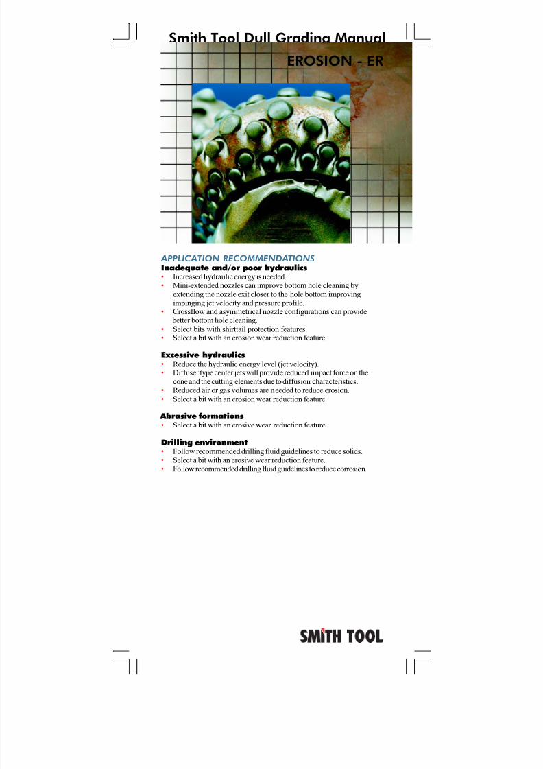
7/11/2019 Bit Dull Grade
http://slidepdf.com/reader/full/bit-dull-grade 73/99
Smith Tool Dull Grading Manual
APPLICATION RECOMMENDATIONS
Inadequate and/or poor hydraulics• Increased hydraulic energy is needed.• Mini-extended nozzles can improve bottom hole cleaning by
extending the nozzle exit closer to the hole bottom improvingimpinging jet velocity and pressure profile.
• Crossflow and asymmetrical nozzle configurations can provide better bottom hole cleaning.
• Select bits with shirttail protection features.• Select a bit with an erosion wear reduction feature.
Excessive hydraulics• Reduce the hydraulic energy level (jet velocity).• Diffuser type center jets will provide reduced impact force on the
cone and the cutting elements due to diffusion characteristics.• Reduced air or gas volumes are needed to reduce erosion.• Select a bit with an erosion wear reduction feature.
Abrasive formations• Select a bit with an erosive wear reduction feature.
Drilling environment• Follow recommended drilling fluid guidelines to reduce solids.• Select a bit with an erosive wear reduction feature.• Follow recommended drilling fluid guidelines to reduce corrosion.
EROSION - ER
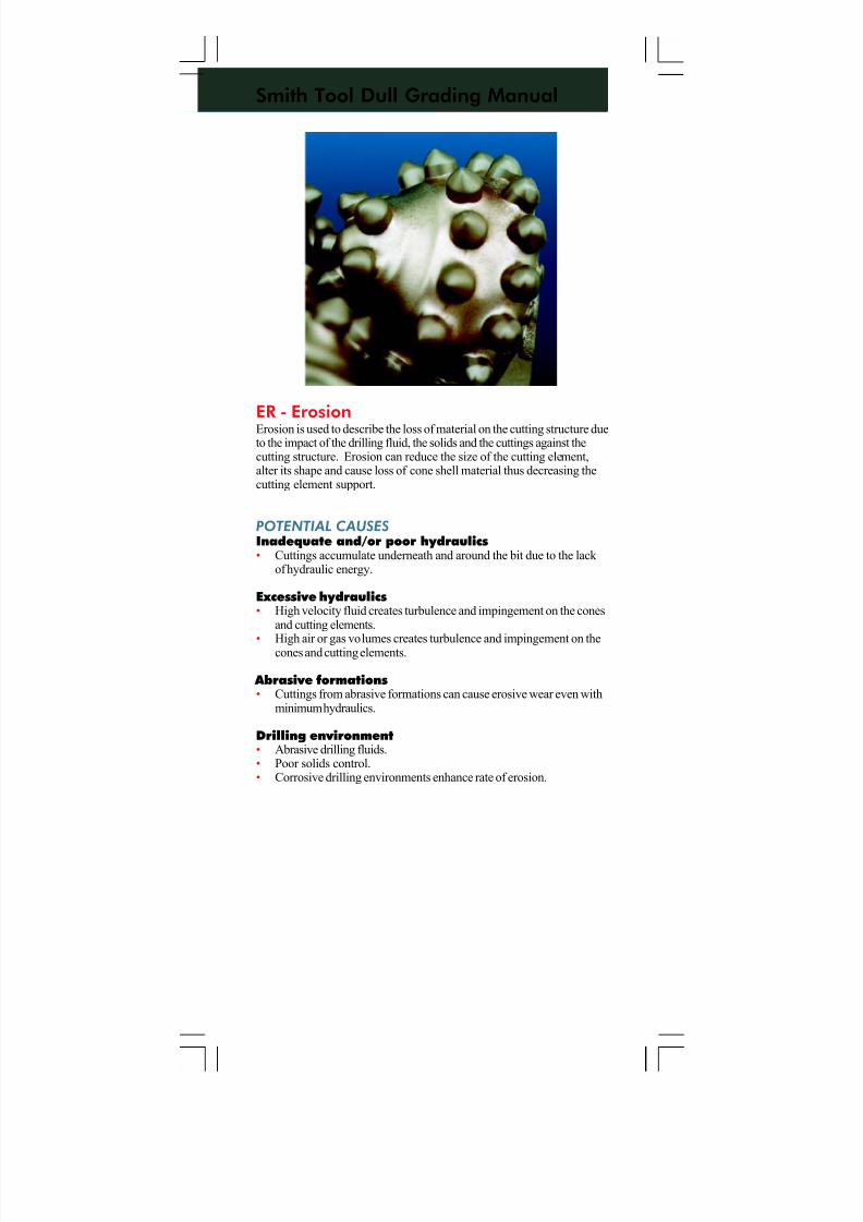
7/11/2019 Bit Dull Grade
http://slidepdf.com/reader/full/bit-dull-grade 74/99
Smith Tool Dull Grading Manual
ER - ErosionErosion is used to describe the loss of material on the cutting structure dueto the impact of the drilling fluid, the solids and the cuttings against thecutting structure. Erosion can reduce the size of the cutting element,alter its shape and cause loss of cone shell material thus decreasing thecutting element support.
POTENTIAL CAUSES
Inadequate and/or poor hydraulics• Cuttings accumulate underneath and around the bit due to the lack
of hydraulic energy.
Excessive hydraulics• High velocity fluid creates turbulence and impingement on the cones
and cutting elements.
• High air or gas volumes creates turbulence and impingement on thecones and cutting elements.
Abrasive formations• Cuttings from abrasive formations can cause erosive wear even with
minimum hydraulics.
Drilling environment• Abrasive drilling fluids.• Poor solids control.• Corrosive drilling environments enhance rate of erosion.
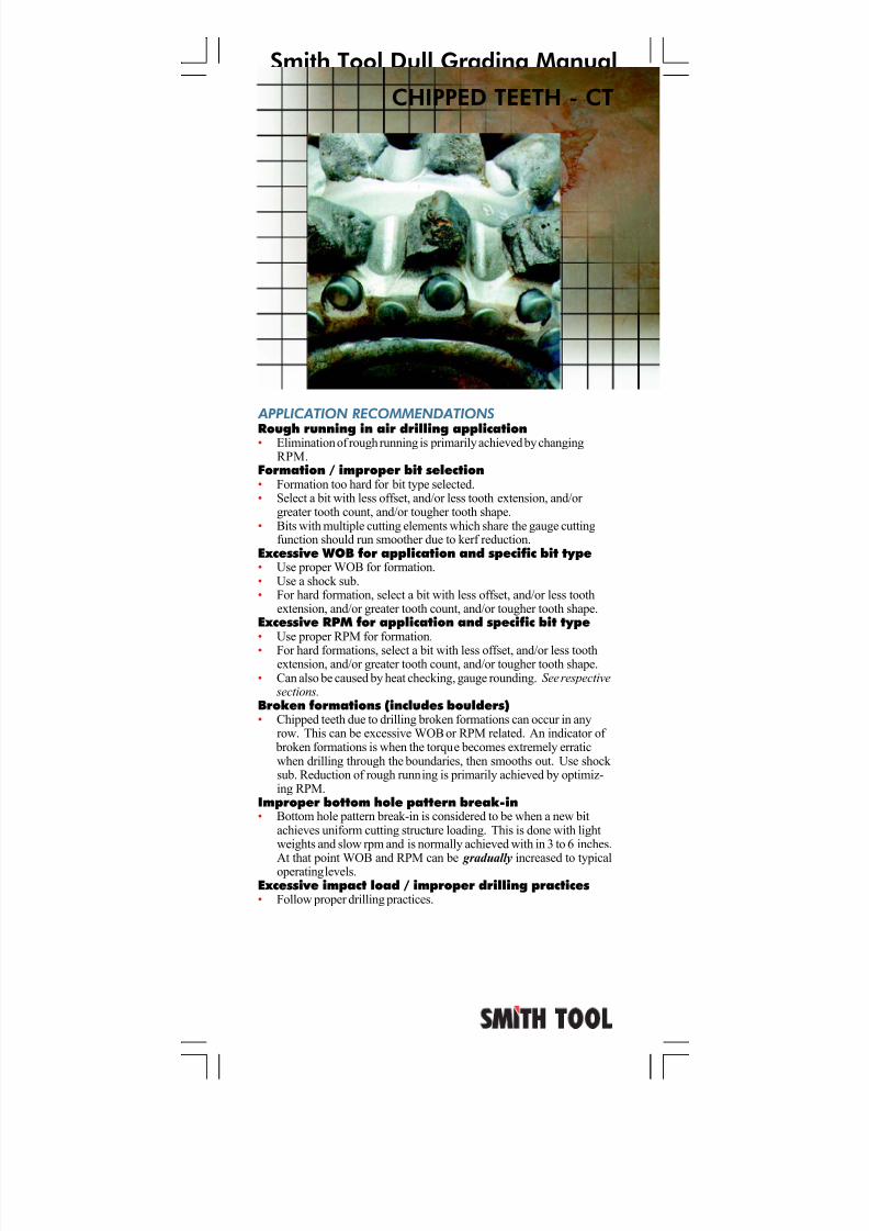
7/11/2019 Bit Dull Grade
http://slidepdf.com/reader/full/bit-dull-grade 75/99
Smith Tool Dull Grading Manual
CHIPPED TEETH - CT
APPLICATION RECOMMENDATIONS
Rough running in air drilling application• Elimination of rough running is primarily achieved by changingRPM.
Formation / improper bit selection• Formation too hard for bit type selected.• Select a bit with less offset, and/or less tooth extension, and/or
greater tooth count, and/or tougher tooth shape.• Bits with multiple cutting elements which share the gauge cutting
function should run smoother due to kerf reduction.Excessive WOB for application and specific bit type• Use proper WOB for formation.• Use a shock sub.• For hard formation, select a bit with less offset, and/or less tooth
extension, and/or greater tooth count, and/or tougher tooth shape.Excessive RPM for application and specific bit type• Use proper RPM for formation.
• For hard formations, select a bit with less offset, and/or less toothextension, and/or greater tooth count, and/or tougher tooth shape.
• Can also be caused by heat checking, gauge rounding. See respective sections.
Broken formations (includes boulders)• Chipped teeth due to drilling broken formations can occur in any
row. This can be excessive WOB or RPM related. An indicator of broken formations is when the torque becomes extremely erraticwhen drilling through the boundaries, then smooths out. Use shock sub. Reduction of rough running is primarily achieved by optimiz-ing RPM.
Improper bottom hole pattern break-in• Bottom hole pattern break-in is considered to be when a new bit
achieves uniform cutting structure loading. This is done with lightweights and slow rpm and is normally achieved with in 3 to 6 inches.
At that point WOB and RPM can be gradually increased to typicaloperating levels.Excessive impact load / improper drilling practices• Follow proper drilling practices.
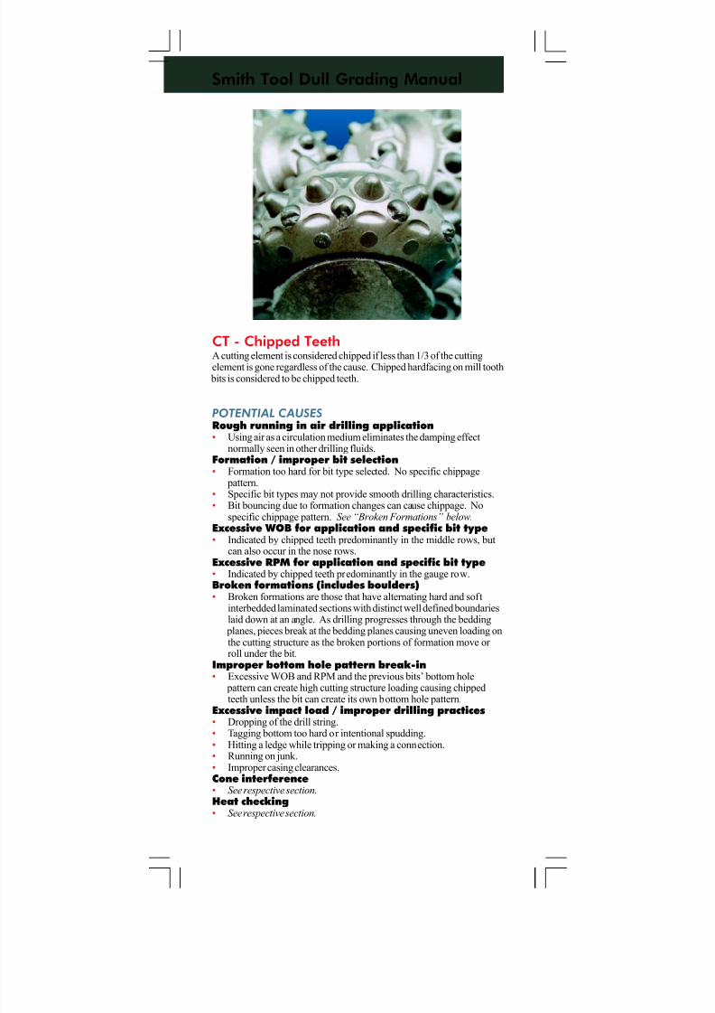
7/11/2019 Bit Dull Grade
http://slidepdf.com/reader/full/bit-dull-grade 76/99
Smith Tool Dull Grading Manual
CT - Chipped TeethA cutting element is considered chipped if less than 1/3 of the cuttingelement is gone regardless of the cause. Chipped hardfacing on mill tooth
bits is considered to be chipped teeth.
POTENTIAL CAUSES
Rough running in air drilling application• Using air as a circulation medium eliminates the damping effect
normally seen in other drilling fluids.Formation / improper bit selection• Formation too hard for bit type selected. No specific chippage
pattern.• Specific bit types may not provide smooth drilling characteristics.• Bit bouncing due to formation changes can cause chippage. No
specific chippage pattern. See “Broken Formations” below.
Excessive WOB for application and specific bit type• Indicated by chipped teeth predominantly in the middle rows, butcan also occur in the nose rows.
Excessive RPM for application and specific bit type• Indicated by chipped teeth predominantly in the gauge row.Broken formations (includes boulders)• Broken formations are those that have alternating hard and soft
interbedded laminated sections with distinct well defined boundarieslaid down at an angle. As drilling progresses through the bedding
planes, pieces break at the bedding planes causing uneven loading onthe cutting structure as the broken portions of formation move or roll under the bit.
Improper bottom hole pattern break-in• Excessive WOB and RPM and the previous bits’ bottom hole
pattern can create high cutting structure loading causing chippedteeth unless the bit can create its own bottom hole pattern.
Excessive impact load / improper drilling practices• Dropping of the drill string.• Tagging bottom too hard or intentional spudding.• Hitting a ledge while tripping or making a connection.• Running on junk.• Improper casing clearances.Cone interference• See respective section.Heat checking• See respective section.
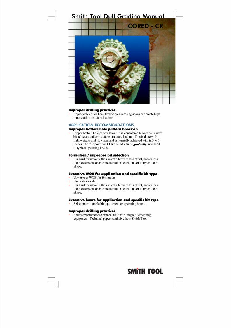
7/11/2019 Bit Dull Grade
http://slidepdf.com/reader/full/bit-dull-grade 77/99
Smith Tool Dull Grading Manual
CORED - CR
Improper drilling practices
• Improperly drilled back flow valves in casing shoes can create highinner cutting structure loading.
APPLICATION RECOMMENDATIONS
Improper bottom hole pattern break-in• Proper bottom hole pattern break-in is considered to be when a new
bit achieves uniform cutting structure loading. This is done withlight weights and slow rpm and is normally achieved with in 3 to 6inches. At that point WOB and RPM can be gradually increasedto typical operating levels.
Formation / improper bit selection• For hard formations, then select a bit with less offset, and/or less
tooth extension, and/or greater tooth count, and/or tougher toothshape.
Excessive WOB for application and specific bit type• Use proper WOB for formation.• Use a shock sub.• For hard formations, then select a bit with less offset, and/or less
tooth extension, and/or greater tooth count, and/or tougher toothshape.
Excessive hours for application and specific bit type• Select more durable bit type or reduce operating hours.
Improper drilling practices• Follow recommended procedures for drilling out cementing
equipment. Technical papers available from Smith Tool.
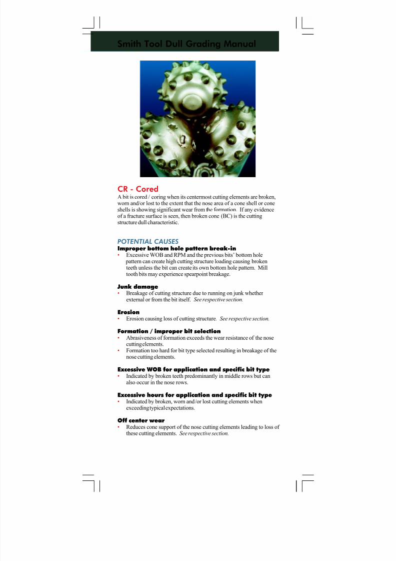
7/11/2019 Bit Dull Grade
http://slidepdf.com/reader/full/bit-dull-grade 78/99
Smith Tool Dull Grading Manual
CR - CoredA bit is cored / coring when its centermost cutting elements are broken,worn and/or lost to the extent that the nose area of a cone shell or coneshells is showing significant wear from the formation. If any evidenceof a fracture surface is seen, then broken cone (BC) is the cuttingstructure dull characteristic.
POTENTIAL CAUSES
Improper bottom hole pattern break-in• Excessive WOB and RPM and the previous bits’ bottom hole
pattern can create high cutting structure loading causing brokenteeth unless the bit can create its own bottom hole pattern. Milltooth bits may experience spearpoint breakage.
Junk damage
• Breakage of cutting structure due to running on junk whether external or from the bit itself. See respective section.
Erosion• Erosion causing loss of cutting structure. See respective section.
Formation / improper bit selection• Abrasiveness of formation exceeds the wear resistance of the nose
cutting elements.• Formation too hard for bit type selected resulting in breakage of the
nose cutting elements.
Excessive WOB for application and specific bit type• Indicated by broken teeth predominantly in middle rows but can
also occur in the nose rows.
Excessive hours for application and specific bit type• Indicated by broken, worn and/or lost cutting elements when
exceeding typical expectations.
Off center wear• Reduces cone support of the nose cutting elements leading to loss of
these cutting elements. See respective section.
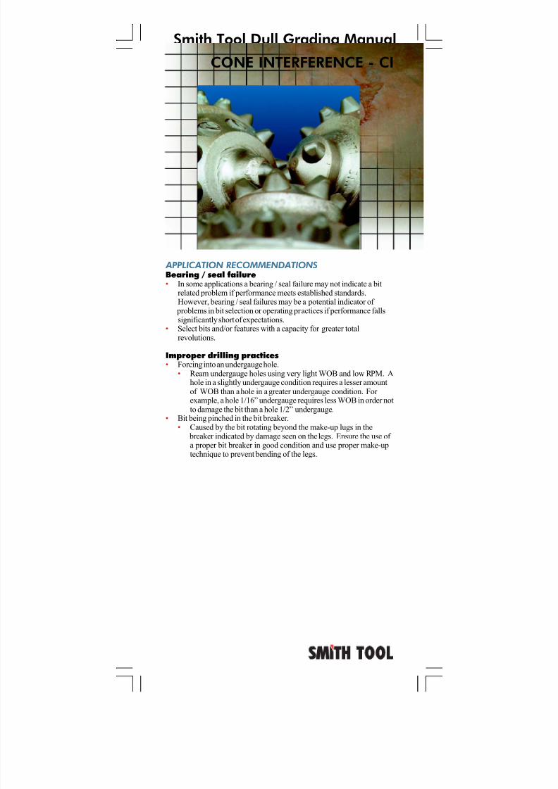
7/11/2019 Bit Dull Grade
http://slidepdf.com/reader/full/bit-dull-grade 79/99
Smith Tool Dull Grading Manual
APPLICATION RECOMMENDATIONS
Bearing / seal failure• In some applications a bearing / seal failure may not indicate a bitrelated problem if performance meets established standards.However, bearing / seal failures may be a potential indicator of
problems in bit selection or operating practices if performance fallssignificantly short of expectations.
• Select bits and/or features with a capacity for greater totalrevolutions.
Improper drilling practices• Forcing into an undergauge hole.
• Ream undergauge holes using very light WOB and low RPM. Ahole in a slightly undergauge condition requires a lesser amountof WOB than a hole in a greater undergauge condition. For example, a hole 1/16” undergauge requires less WOB in order notto damage the bit than a hole 1/2” undergauge.
• Bit being pinched in the bit breaker.• Caused by the bit rotating beyond the make-up lugs in the
breaker indicated by damage seen on the legs. Ensure the use of a proper bit breaker in good condition and use proper make-uptechnique to prevent bending of the legs.
CONE INTERFERENCE - CI
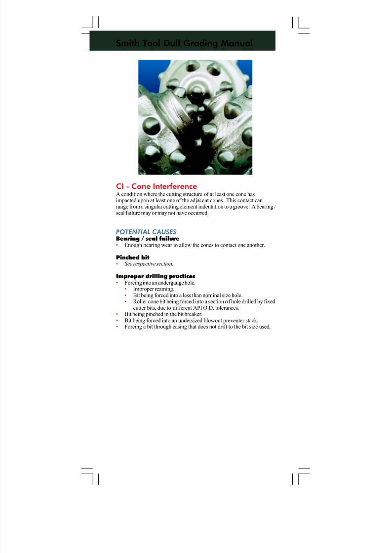
7/11/2019 Bit Dull Grade
http://slidepdf.com/reader/full/bit-dull-grade 80/99
Smith Tool Dull Grading Manual
CI - Cone InterferenceA condition where the cutting structure of at least one cone hasimpacted upon at least one of the adjacent cones. This contact canrange from a singular cutting element indentation to a groove. A bearing /seal failure may or may not have occurred.
POTENTIAL CAUSES
Bearing / seal failure• Enough bearing wear to allow the cones to contact one another.
Pinched bit• See respective section.
Improper drilling practices• Forcing into an undergauge hole.
• Improper reaming.• Bit being forced into a less than nominal size hole.• Roller cone bit being forced into a section of hole drilled by fixed
cutter bits, due to different API O.D. tolerances.• Bit being pinched in the bit breaker.• Bit being forced into an undersized blowout preventer stack.• Forcing a bit through casing that does not drift to the bit size used.
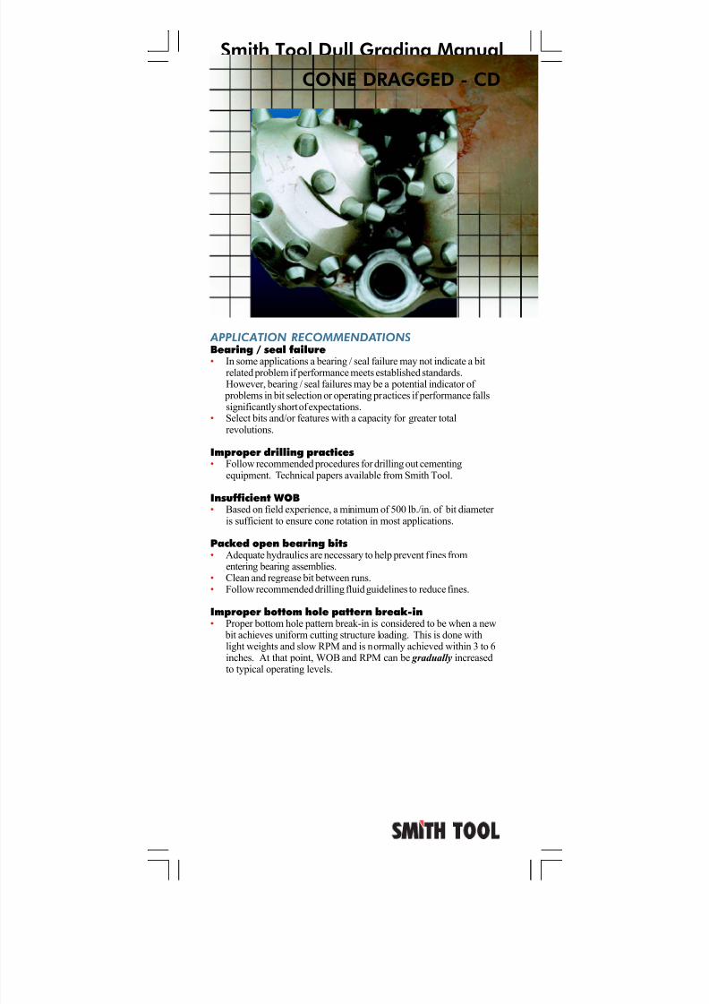
7/11/2019 Bit Dull Grade
http://slidepdf.com/reader/full/bit-dull-grade 81/99
Smith Tool Dull Grading Manual
APPLICATION RECOMMENDATIONS
Bearing / seal failure• In some applications a bearing / seal failure may not indicate a bitrelated problem if performance meets established standards.However, bearing / seal failures may be a potential indicator of
problems in bit selection or operating practices if performance fallssignificantly short of expectations.
• Select bits and/or features with a capacity for greater totalrevolutions.
Improper drilling practices• Follow recommended procedures for drilling out cementing
equipment. Technical papers available from Smith Tool.
Insufficient WOB• Based on field experience, a minimum of 500 lb./in. of bit diameter
is sufficient to ensure cone rotation in most applications.
Packed open bearing bits• Adequate hydraulics are necessary to help prevent fines from
entering bearing assemblies.• Clean and regrease bit between runs.• Follow recommended drilling fluid guidelines to reduce fines.
Improper bottom hole pattern break-in• Proper bottom hole pattern break-in is considered to be when a new
bit achieves uniform cutting structure loading. This is done withlight weights and slow RPM and is normally achieved within 3 to 6inches. At that point, WOB and RPM can be gradually increasedto typical operating levels.
CONE DRAGGED - CD
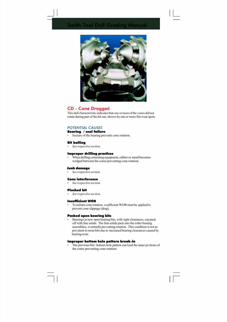
7/11/2019 Bit Dull Grade
http://slidepdf.com/reader/full/bit-dull-grade 82/99
Smith Tool Dull Grading Manual
CD - Cone DraggedThis dull characteristic indicates that one or more of the cones did notrotate during part of the bit run, shown by one or more flat wear spots.
POTENTIAL CAUSES
Bearing / seal failure• Seizure of the bearing prevents cone rotation.
Bit balling• See respective section.
Improper drilling practices• When drilling cementing equipment, rubber or metal becomes
wedged between the cones preventing cone rotation.
Junk damage• See respective section.
Cone interference• See respective section.
Pinched bit• See respective section.
Insufficient WOB• To initiate cone rotation, a sufficient WOB must be applied to
prevent cone slippage (drag).
Packed open bearing bits• Bearings in new open bearing bits, with tight clearances, can pack
off with fine solids. The fine solids pack into the roller bearing
assemblies, eventually preventing rotation. This condition is not as prevalent in rerun bits due to increased bearing clearances caused by bearing wear.
Improper bottom hole pattern break-in• The previous bits’ bottom hole pattern can load the inner portions of
the cones preventing cone rotation.
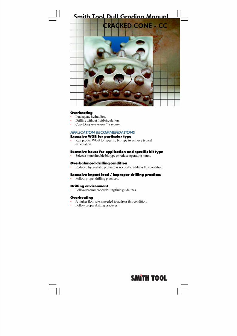
7/11/2019 Bit Dull Grade
http://slidepdf.com/reader/full/bit-dull-grade 83/99
Smith Tool Dull Grading Manual
Overheating
• Inadequate hydraulics.• Drilling without fluid circulation.• Cone Drag - see respective section.
APPLICATION RECOMMENDATIONS
Excessive WOB for particular type• Run proper WOB for specific bit type to achieve typical
expectation.
Excessive hours for application and specific bit type• Select a more durable bit type or reduce operating hours.
Overbalanced drilling condition• Reduced hydrostatic pressure is needed to address this condition.
Excessive impact load / improper drilling practices• Follow proper drilling practices.
Drilling environment• Follow recommended drilling fluid guidelines.
Overheating• A higher flow rate is needed to address this condition.• Follow proper drilling practices.
CRACKED CONE - CC
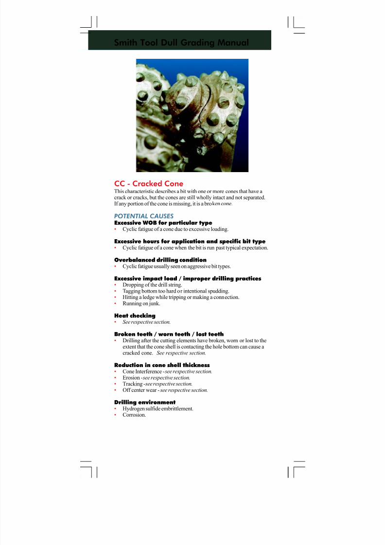
7/11/2019 Bit Dull Grade
http://slidepdf.com/reader/full/bit-dull-grade 84/99
Smith Tool Dull Grading Manual
CC - Cracked ConeThis characteristic describes a bit with one or more cones that have acrack or cracks, but the cones are still wholly intact and not separated.If any portion of the cone is missing, it is a broken cone.
POTENTIAL CAUSES
Excessive WOB for particular type• Cyclic fatigue of a cone due to excessive loading.
Excessive hours for application and specific bit type• Cyclic fatigue of a cone when the bit is run past typical expectation.
Overbalanced drilling condition• Cyclic fatigue usually seen on aggressive bit types.
Excessive impact load / improper drilling practices
• Dropping of the drill string.• Tagging bottom too hard or intentional spudding.• Hitting a ledge while tripping or making a connection.• Running on junk.
Heat checking• See respective section.
Broken teeth / worn teeth / lost teeth• Drilling after the cutting elements have broken, worn or lost to the
extent that the cone shell is contacting the hole bottom can cause acracked cone. See respective section.
Reduction in cone shell thickness• Cone Interference - see respective section.• Erosion - see respective section.
• Tracking - see respective section.• Off center wear - see respective section.
Drilling environment• Hydrogen sulfide embrittlement.• Corrosion.
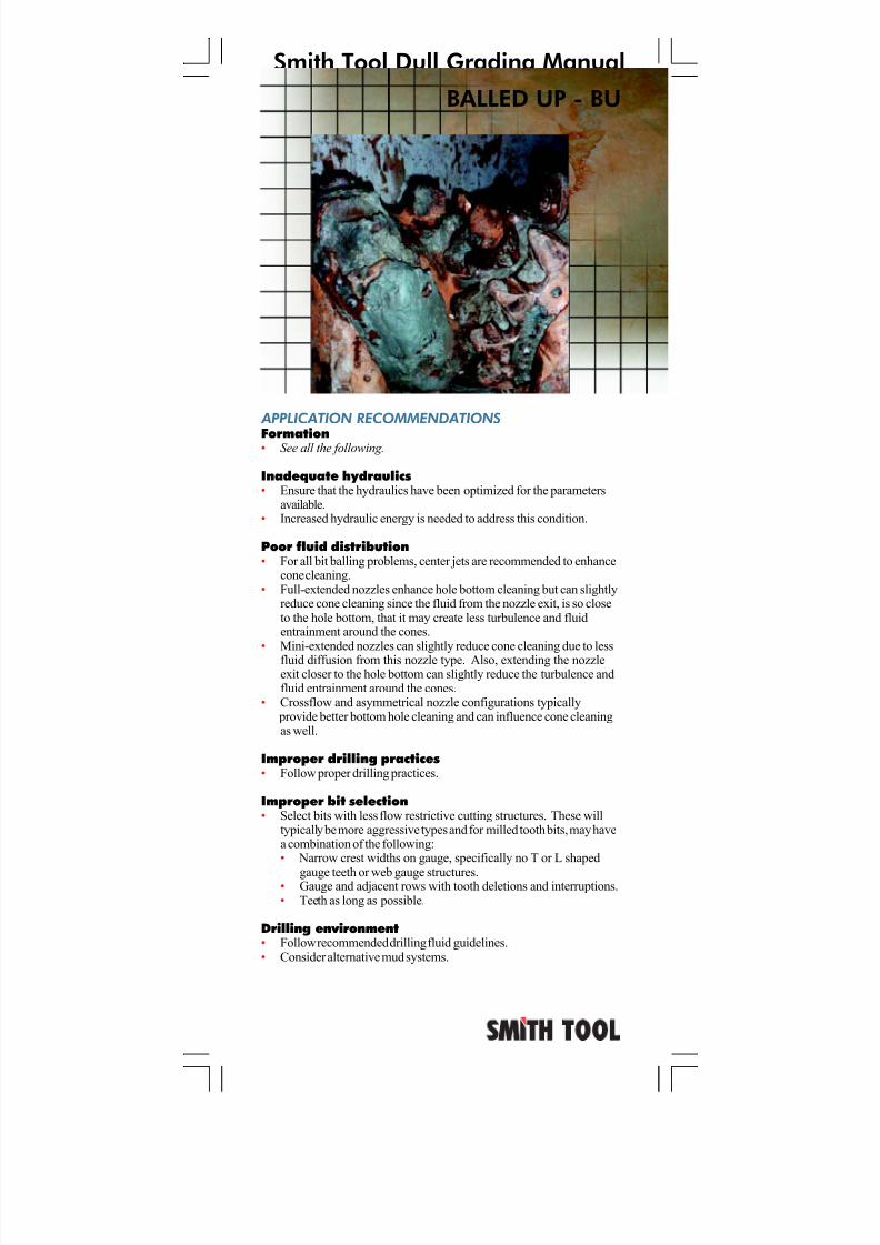
7/11/2019 Bit Dull Grade
http://slidepdf.com/reader/full/bit-dull-grade 85/99
Smith Tool Dull Grading Manual
APPLICATION RECOMMENDATIONS
Formation• See all the following.
Inadequate hydraulics• Ensure that the hydraulics have been optimized for the parameters
available.• Increased hydraulic energy is needed to address this condition.
Poor fluid distribution• For all bit balling problems, center jets are recommended to enhance
cone cleaning.• Full-extended nozzles enhance hole bottom cleaning but can slightly
reduce cone cleaning since the fluid from the nozzle exit, is so closeto the hole bottom, that it may create less turbulence and fluidentrainment around the cones.
• Mini-extended nozzles can slightly reduce cone cleaning due to lessfluid diffusion from this nozzle type. Also, extending the nozzleexit closer to the hole bottom can slightly reduce the turbulence andfluid entrainment around the cones.
• Crossflow and asymmetrical nozzle configurations typically provide better bottom hole cleaning and can influence cone cleaningas well.
Improper drilling practices• Follow proper drilling practices.
Improper bit selection• Select bits with less flow restrictive cutting structures. These will
typically be more aggressive types and for milled tooth bits, may havea combination of the following:• Narrow crest widths on gauge, specifically no T or L shaped
gauge teeth or web gauge structures.• Gauge and adjacent rows with tooth deletions and interruptions.• Teeth as long as possible.
Drilling environment• Follow recommended drilling fluid guidelines.• Consider alternative mud systems.
BALLED UP - BU
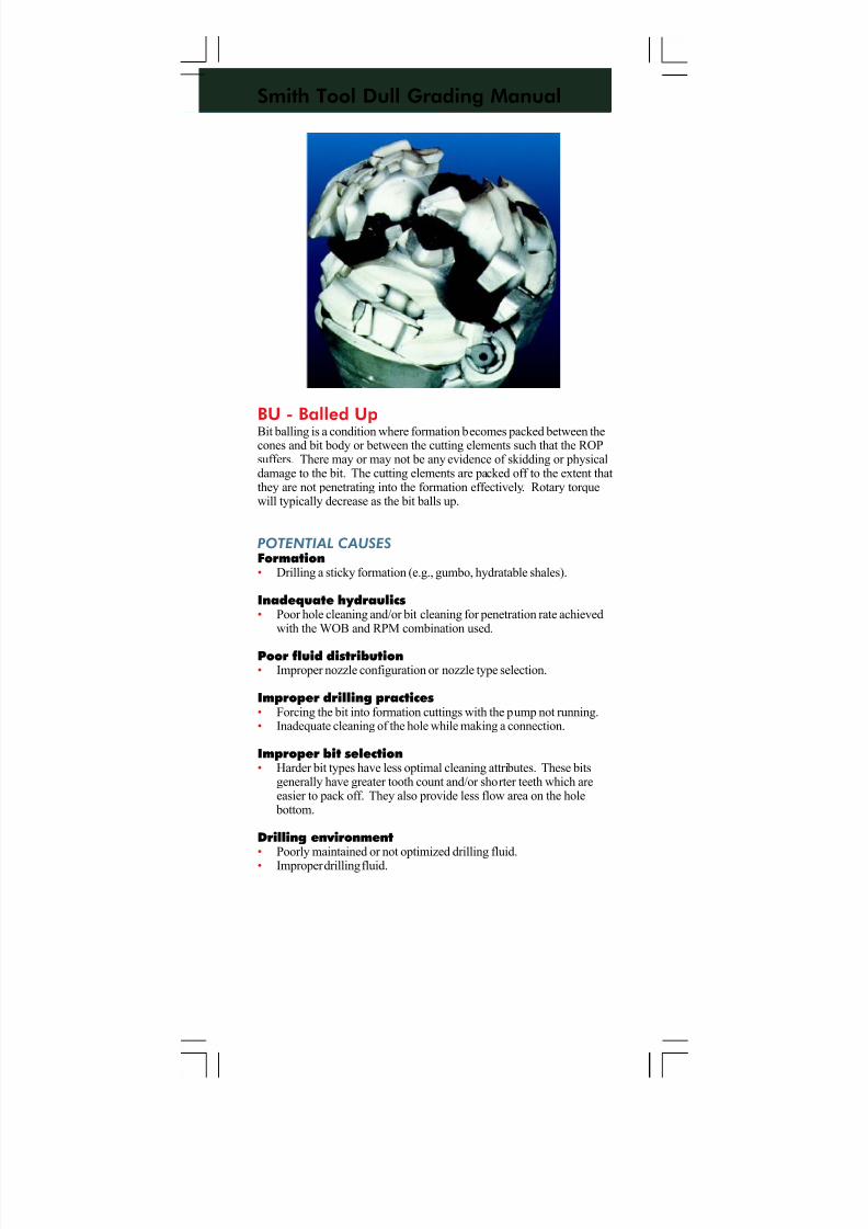
7/11/2019 Bit Dull Grade
http://slidepdf.com/reader/full/bit-dull-grade 86/99
Smith Tool Dull Grading Manual
BU - Balled UpBit balling is a condition where formation becomes packed between thecones and bit body or between the cutting elements such that the ROPsuffers. There may or may not be any evidence of skidding or physicaldamage to the bit. The cutting elements are packed off to the extent thatthey are not penetrating into the formation effectively. Rotary torquewill typically decrease as the bit balls up.
POTENTIAL CAUSES
Formation• Drilling a sticky formation (e.g., gumbo, hydratable shales).
Inadequate hydraulics• Poor hole cleaning and/or bit cleaning for penetration rate achieved
with the WOB and RPM combination used.
Poor fluid distribution• Improper nozzle configuration or nozzle type selection.
Improper drilling practices• Forcing the bit into formation cuttings with the pump not running.• Inadequate cleaning of the hole while making a connection.
Improper bit selection• Harder bit types have less optimal cleaning attributes. These bits
generally have greater tooth count and/or shorter teeth which areeasier to pack off. They also provide less flow area on the hole
bottom.
Drilling environment• Poorly maintained or not optimized drilling fluid.
• Improper drilling fluid.
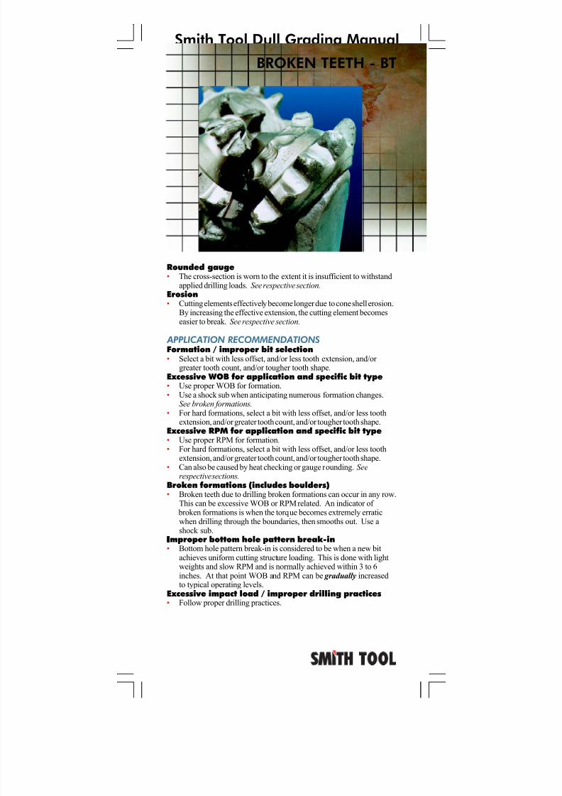
7/11/2019 Bit Dull Grade
http://slidepdf.com/reader/full/bit-dull-grade 87/99
Smith Tool Dull Grading Manual
BROKEN TEETH - BT
Rounded gauge
• The cross-section is worn to the extent it is insufficient to withstandapplied drilling loads. See respective section.Erosion• Cutting elements effectively become longer due to cone shell erosion.
By increasing the effective extension, the cutting element becomeseasier to break. See respective section.
APPLICATION RECOMMENDATIONS
Formation / improper bit selection• Select a bit with less offset, and/or less tooth extension, and/or
greater tooth count, and/or tougher tooth shape.Excessive WOB for application and specific bit type• Use proper WOB for formation.• Use a shock sub when anticipating numerous formation changes.
See broken formations.• For hard formations, select a bit with less offset, and/or less tooth
extension, and/or greater tooth count, and/or tougher tooth shape.Excessive RPM for application and specific bit type• Use proper RPM for formation.• For hard formations, select a bit with less offset, and/or less tooth
extension, and/or greater tooth count, and/or tougher tooth shape.• Can also be caused by heat checking or gauge rounding. See
respective sections.Broken formations (includes boulders)• Broken teeth due to drilling broken formations can occur in any row.
This can be excessive WOB or RPM related. An indicator of broken formations is when the torque becomes extremely erraticwhen drilling through the boundaries, then smooths out. Use ashock sub.
IIIIImproper bottom hole pattern break-in• Bottom hole pattern break-in is considered to be when a new bit
achieves uniform cutting structure loading. This is done with lightweights and slow RPM and is normally achieved within 3 to 6inches. At that point WOB and RPM can be gradually increasedto typical operating levels.
Excessive impact load / improper drilling practices• Follow proper drilling practices.
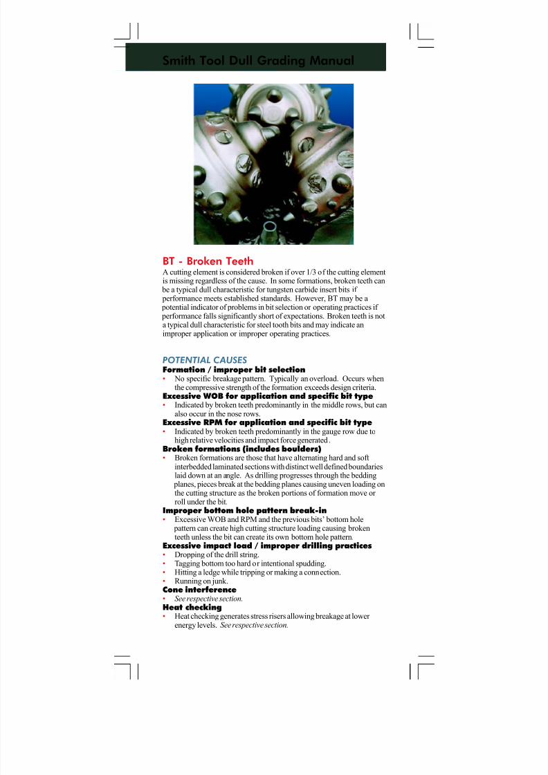
7/11/2019 Bit Dull Grade
http://slidepdf.com/reader/full/bit-dull-grade 88/99
Smith Tool Dull Grading Manual
BT - Broken TeethA cutting element is considered broken if over 1/3 of the cutting elementis missing regardless of the cause. In some formations, broken teeth can
be a typical dull characteristic for tungsten carbide insert bits if performance meets established standards. However, BT may be a potential indicator of problems in bit selection or operating practices if performance falls significantly short of expectations. Broken teeth is nota typical dull characteristic for steel tooth bits and may indicate animproper application or improper operating practices.
POTENTIAL CAUSES
Formation / improper bit selection• No specific breakage pattern. Typically an overload. Occurs when
the compressive strength of the formation exceeds design criteria.Excessive WOB for application and specific bit type
• Indicated by broken teeth predominantly in the middle rows, but canalso occur in the nose rows.Excessive RPM for application and specific bit type• Indicated by broken teeth predominantly in the gauge row due to
high relative velocities and impact force generated .Broken formations (includes boulders)• Broken formations are those that have alternating hard and soft
interbedded laminated sections with distinct well defined boundarieslaid down at an angle. As drilling progresses through the bedding
planes, pieces break at the bedding planes causing uneven loading onthe cutting structure as the broken portions of formation move or roll under the bit.
Improper bottom hole pattern break-in• Excessive WOB and RPM and the previous bits’ bottom hole
pattern can create high cutting structure loading causing brokenteeth unless the bit can create its own bottom hole pattern.
Excessive impact load / improper drilling practices• Dropping of the drill string.• Tagging bottom too hard or intentional spudding.• Hitting a ledge while tripping or making a connection.• Running on junk.Cone interference• See respective section.Heat checking• Heat checking generates stress risers allowing breakage at lower
energy levels. See respective section.
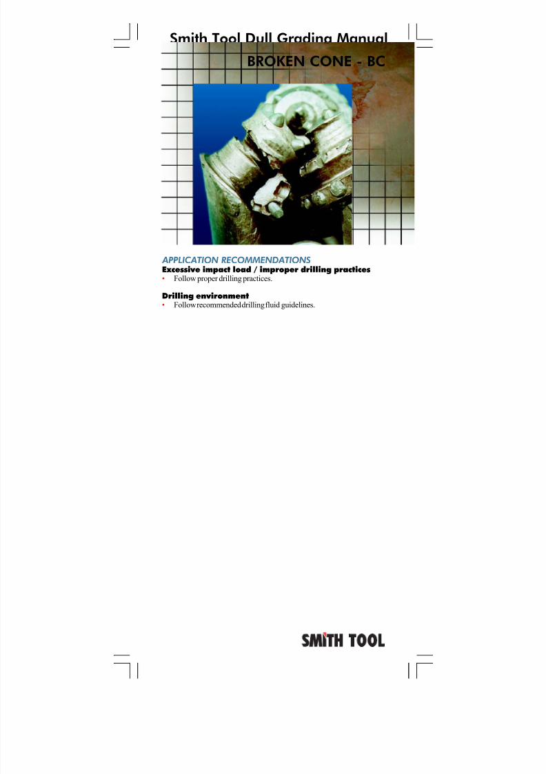
7/11/2019 Bit Dull Grade
http://slidepdf.com/reader/full/bit-dull-grade 89/99
Smith Tool Dull Grading Manual
APPLICATION RECOMMENDATIONS
Excessive impact load / improper drilling practices• Follow proper drilling practices.
Drilling environment• Follow recommended drilling fluid guidelines.
BROKEN CONE - BC
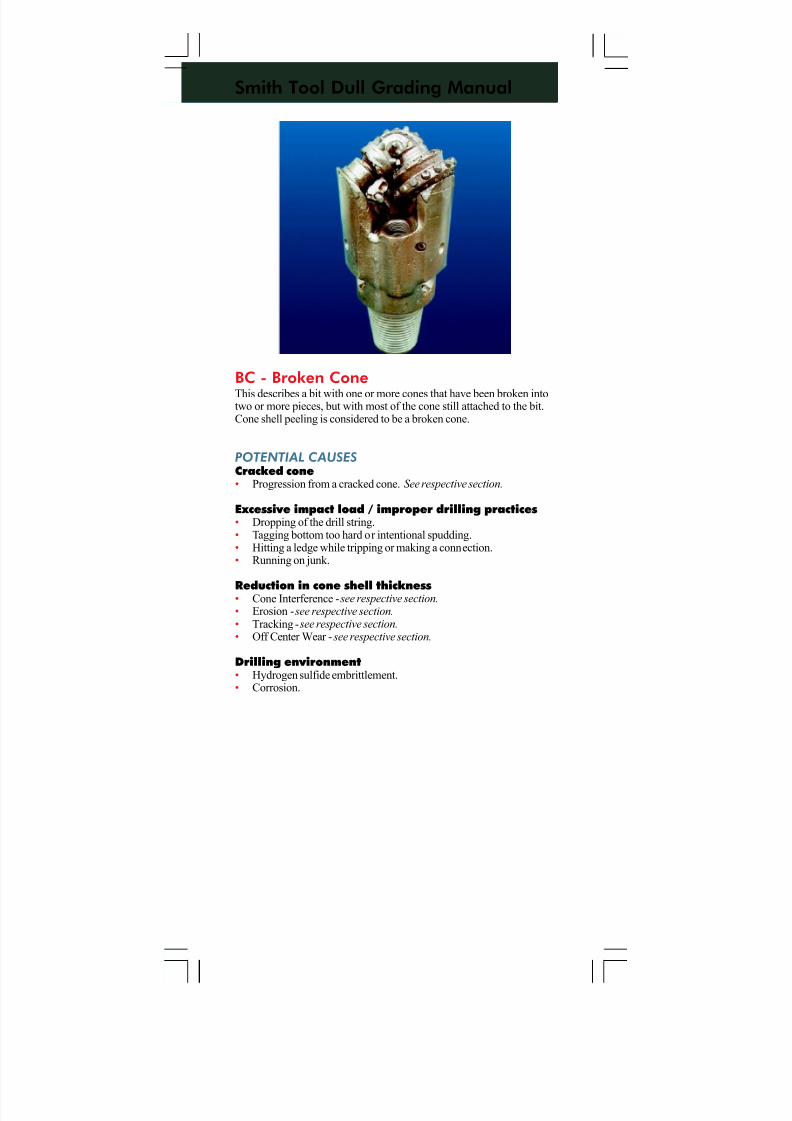
7/11/2019 Bit Dull Grade
http://slidepdf.com/reader/full/bit-dull-grade 90/99
Smith Tool Dull Grading Manual
BC - Broken ConeThis describes a bit with one or more cones that have been broken intotwo or more pieces, but with most of the cone still attached to the bit.Cone shell peeling is considered to be a broken cone.
POTENTIAL CAUSES
Cracked cone• Progression from a cracked cone. See respective section.
Excessive impact load / improper drilling practices• Dropping of the drill string.• Tagging bottom too hard or intentional spudding.• Hitting a ledge while tripping or making a connection.• Running on junk.
Reduction in cone shell thickness• Cone Interference - see respective section.• Erosion - see respective section.• Tracking - see respective section.• Off Center Wear - see respective section.
Drilling environment• Hydrogen sulfide embrittlement.• Corrosion.
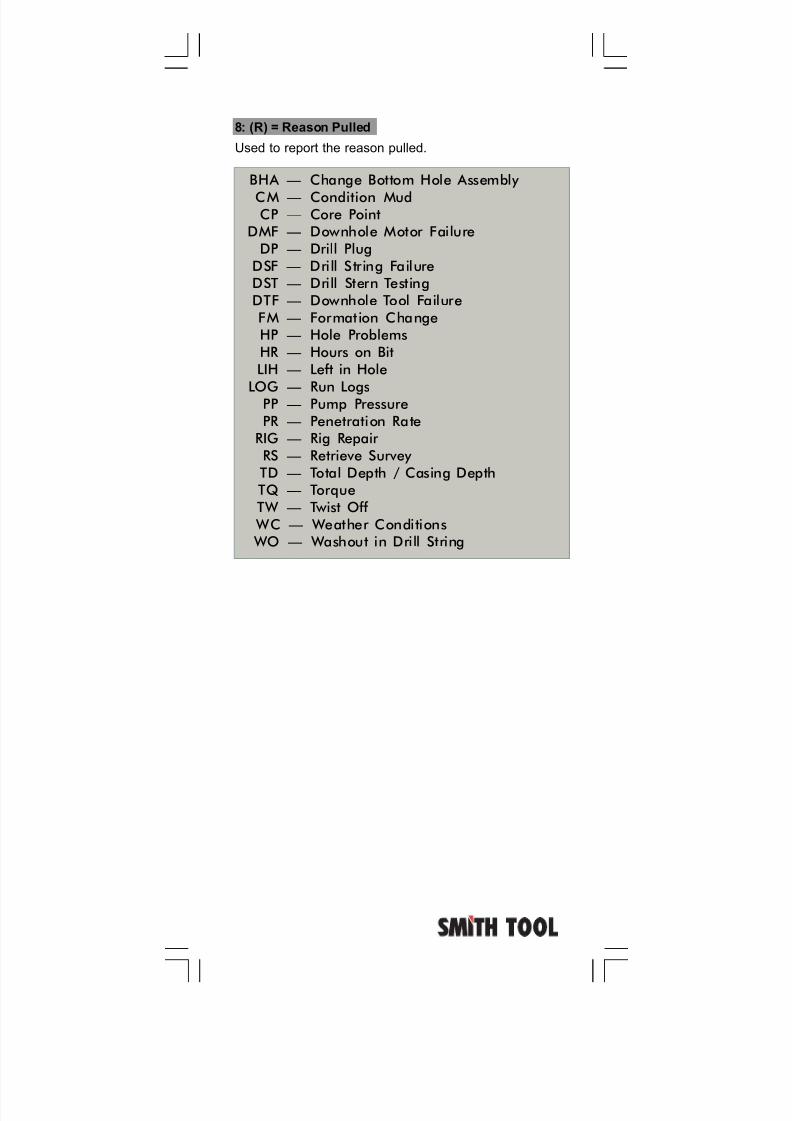
7/11/2019 Bit Dull Grade
http://slidepdf.com/reader/full/bit-dull-grade 91/99
8: (R) = Reason Pulled
Used to report the reason pulled.
BHA — Change Bottom Hole Assembly
CM — Condition MudCP — Core Point
DMF — Downhole Motor FailureDP — Drill Plug
DSF — Drill String FailureDST — Drill Stern TestingDTF — Downhole Tool FailureFM — Formation ChangeHP — Hole ProblemsHR — Hours on BitLIH — Left in Hole
LOG — Run LogsPP — Pump PressurePR — Penetration Rate
RIG — Rig Repair RS — Retrieve Survey TD — Total Depth / Casing DepthTQ — TorqueTW — Twist Off
WC — Weather Conditions WO — Washout in Drill String
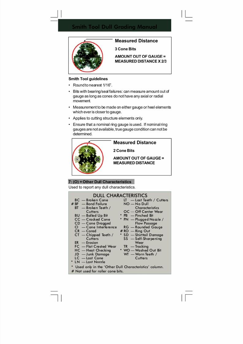
7/11/2019 Bit Dull Grade
http://slidepdf.com/reader/full/bit-dull-grade 92/99
Smith Tool Dull Grading Manual
Smith Tool guidelines
• Round to nearest 1/16”.
• Bits with bearing/seal failures: can measure amount out of
gauge as long as cones do not have any axial or radial
movement.
• Measurement to be made on either gauge or heel elements
which ever is closer to gauge.
• Applies to cutting structure elements only.
• Ensure that a nominal ring gauge is used. If nominal ring
gauges are not available, true gauge condition can not be
determined.
7: (O) = Other Dull Characteristics
Used to report any dull characteristics.
Measured Distance
3 Cone Bits
AMOUNT OUT OF GAUGE =
MEASURED DISTANCE X 2/3
Measured Distance
2 Cone Bits
AMOUNT OUT OF GAUGE =
MEASURED DISTANCE
DULL CHARACTERISTICSBC — Broken Cone
# BF — Bond FailureBT — Broken Teeth /
CuttersBU — Balled Up BitCC — Cracked ConeCD — Cone DraggedCI — Cone InterferenceCR — CoredCT — Chipped Teeth /
CuttersER — ErosionFC — Flat Crested Wear HC — Heat CheckingJD — Junk DamageLC — Lost Cone
* LN — Lost Nozzle
LT — Lost Teeth / CuttersNO — No Dull
CharacteristicsOC — Off Center Wear
* PB — Pinched Bit* PN — Plugged Nozzle /
Flow PassageRG — Rounded Gauge
# RO — Ring Out* SD — Shirttail Damage
SS — Self-Sharpening Wear
TR — Tracking* WO — Washed Out Bit
WT — Worn Teeth /Cutters
* Used only in the ‘Other Dull Characteristics’ column.# Not used for roller cone bits.
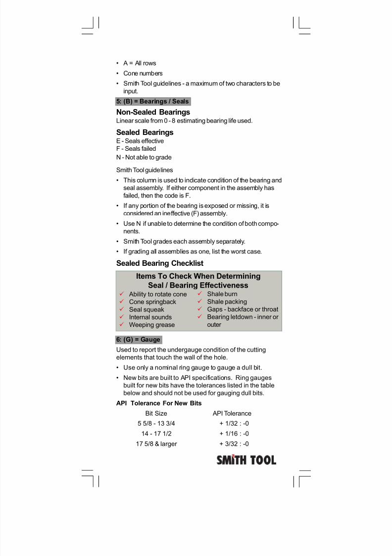
7/11/2019 Bit Dull Grade
http://slidepdf.com/reader/full/bit-dull-grade 93/99
• A = All rows
• Cone numbers
• Smith Tool guidelines - a maximum of two characters to be
input.
5: (B) = Bearings / Seals
Non-Sealed BearingsLinear scale from 0 - 8 estimating bearing life used.
Sealed BearingsE - Seals effective
F - Seals failed
N - Not able to grade
Smith Tool guidelines
• This column is used to indicate condition of the bearing and
seal assembly. If either component in the assembly has
failed, then the code is F.
• If any portion of the bearing is exposed or missing, it is
considered an ineffective (F) assembly.
• Use N if unable to determine the condition of both compo-
nents.
• Smith Tool grades each assembly separately.
• If grading all assemblies as one, list the worst case.
Sealed Bearing Checklist
6: (G) = Gauge
Used to report the undergauge condition of the cutting
elements that touch the wall of the hole.
• Use only a nominal ring gauge to gauge a dull bit.
• New bits are built to API specifications. Ring gauges
built for new bits have the tolerances listed in the table
below and should not be used for gauging dull bits.
API Tolerance For New Bits
Bit Size API Tolerance
5 5/8 - 13 3/4 + 1/32 : -0
14 - 17 1/2 + 1/16 : -0
17 5/8 & larger + 3/32 : -0
Items To Check When Determining
Seal / Bearing Effectiveness
Ability to rotate cone Cone springback
Seal squeak
Internal sounds
Weeping grease
Shale burn Shale packing
Gaps - backface or throat
Bearing letdown - inner or
outer
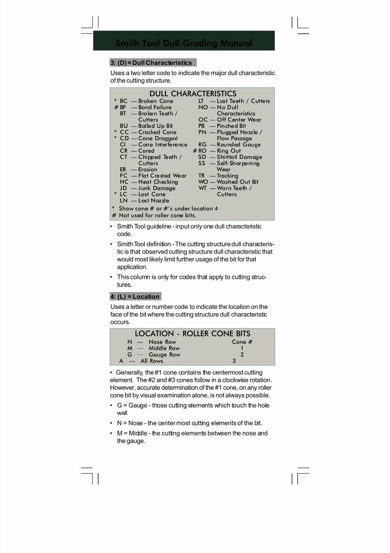
7/11/2019 Bit Dull Grade
http://slidepdf.com/reader/full/bit-dull-grade 94/99
Smith Tool Dull Grading Manual
4: (L) = Location
Uses a letter or number code to indicate the location on the
face of the bit where the cutting structure dull characteristic
occurs.
3: (D) = Dull Characteristics
Uses a two letter code to indicate the major dull characteristic
of the cutting structure.
• Smith Tool guideline - input only one dull characteristic
code.
• Smith Tool definition - The cutting structure dull characteris-
tic is that observed cutting structure dull characteristic that
would most likely limit further usage of the bit for that
application.
• This column is only for codes that apply to cutting struc-
tures.
• Generally, the #1 cone contains the centermost cutting
element. The #2 and #3 cones follow in a clockwise rotation.
However, accurate determination of the #1 cone, on any roller cone bit by visual examination alone, is not always possible.
• G = Gauge - those cutting elements which touch the hole
wall.
• N = Nose - the center most cutting elements of the bit.
• M = Middle - the cutting elements between the nose and
the gauge.
DULL CHARACTERISTICS* BC — Broken Cone# BF — Bond Failure
BT — Broken Teeth /Cutters
BU — Balled Up Bit* CC — Cracked Cone* CD — Cone Dragged
CI — Cone InterferenceCR — CoredCT — Chipped Teeth /
CuttersER — ErosionFC — Flat Crested Wear HC — Heat CheckingJD — Junk Damage
* LC — Lost ConeLN — Lost Nozzle
LT — Lost Teeth / CuttersNO — No Dull
CharacteristicsOC — Off Center Wear PB — Pinched BitPN — Plugged Nozzle /
Flow PassageRG — Rounded Gauge
# RO — Ring OutSD — Shirttail DamageSS — Self-Sharpening
Wear TR — Tracking WO — Washed Out Bit WT — Worn Teeth /
Cutters
* Show cone # or #’s under location 4.# Not used for roller cone bits.
LOCATION - ROLLER CONE BITSN — Nose Row Cone #M — Middle Row 1G — Gauge Row 2 A — All Rows 3
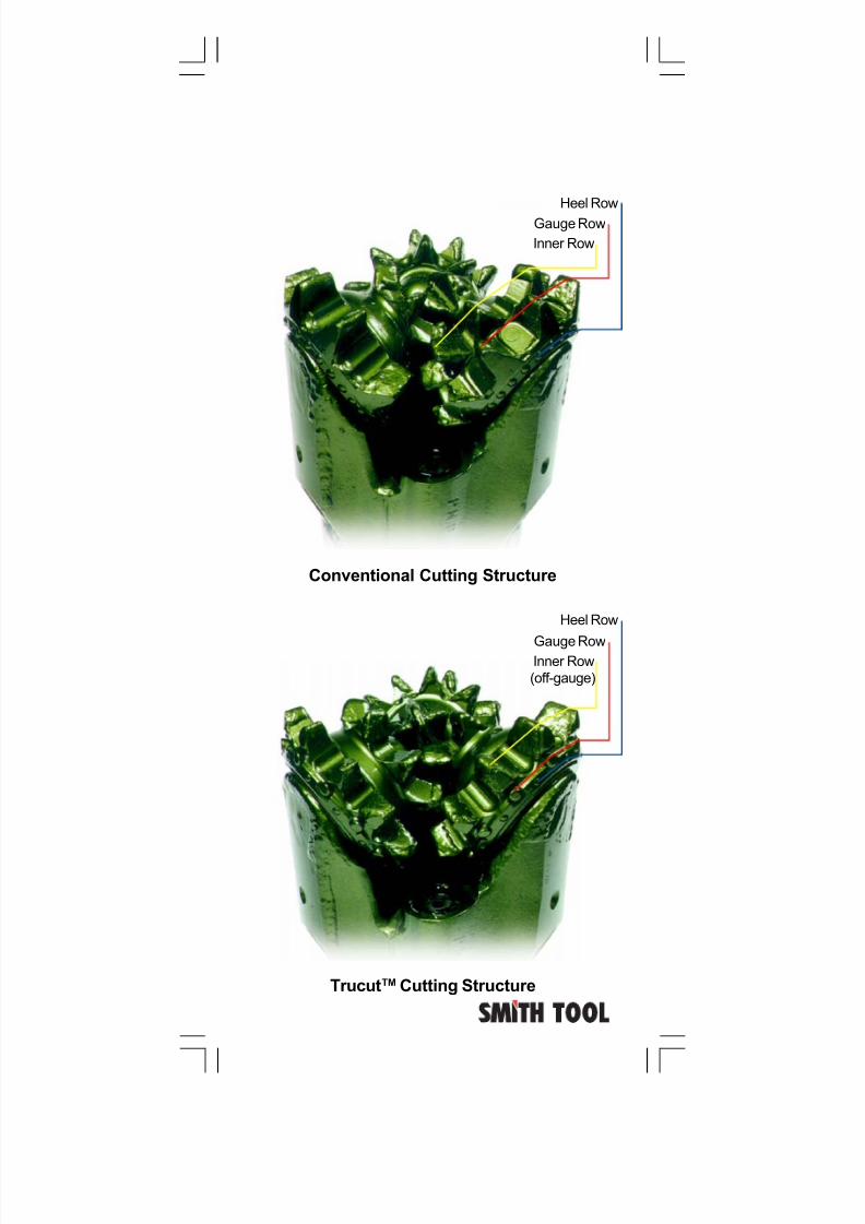
7/11/2019 Bit Dull Grade
http://slidepdf.com/reader/full/bit-dull-grade 95/99
TrucutTM Cutting Structure
Conventional Cutting Structure
Inner Row
(off-gauge)
Gauge Row
Heel Row
Inner Row
Gauge Row
Heel Row
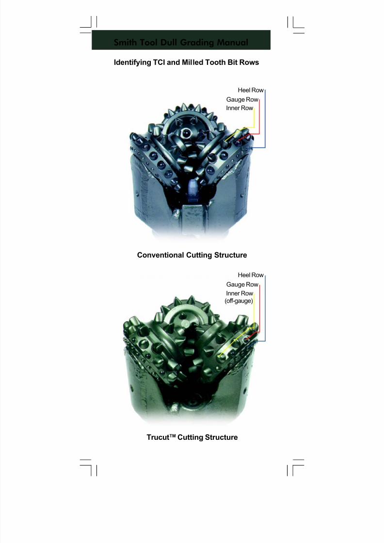
7/11/2019 Bit Dull Grade
http://slidepdf.com/reader/full/bit-dull-grade 96/99
Smith Tool Dull Grading Manual
Identifying TCI and Milled Tooth Bit Rows
Conventional Cutting Structure
TrucutTM Cutting Structure
Inner Row
(off-gauge)
Gauge Row
Heel Row
Inner Row
Gauge Row
Heel Row
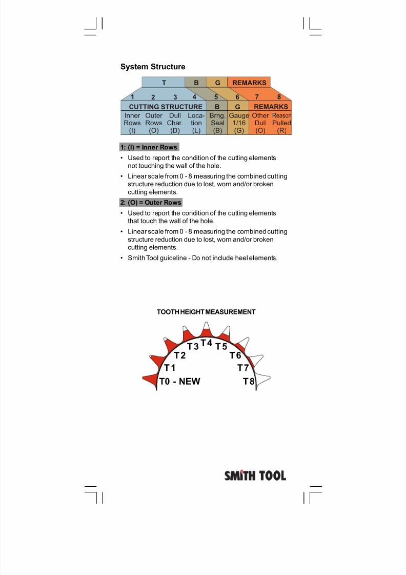
7/11/2019 Bit Dull Grade
http://slidepdf.com/reader/full/bit-dull-grade 97/99
1: (I) = Inner Rows
• Used to report the condition of the cutting elements
not touching the wall of the hole.
• Linear scale from 0 - 8 measuring the combined cutting
structure reduction due to lost, worn and/or broken
cutting elements.
2: (O) = Outer Rows
• Used to report the condition of the cutting elements
that touch the wall of the hole.
• Linear scale from 0 - 8 measuring the combined cutting
structure reduction due to lost, worn and/or broken
cutting elements.
• Smith Tool guideline - Do not include heel elements.
System Structure
Inner Rows(I)
Outer Rows(O)
DullChar.(D)
Loca-tion(L)
Brng.Seal(B)
Gauge1/16(G)
Other Dull(O)
Reason
Pulled(R)
CUTTING STRUCTURE B G REMARKS
BT G REMARKS
12 3
4 56
7 8
TOOTH HEIGHT MEASUREMENT
T0 - NEW T8
T1
T2T3 T4
T7
T6T5
7/11/2019 Bit Dull Grade
http://slidepdf.com/reader/full/bit-dull-grade 98/99
Smith Tool Dull Grading Manual
The Smith Tool definitions and guidelines shown withinare NOT IADC standards. They were created solely for internal purposes to reduce ambiguities and to improveour consistency in grading dull bits within the current
IADC structure.
Authors:
Kerry Koffler Mike Oliver
Jeff Carlone
Alan Lockstedt
Layout and Graphics:
IceBerg Graphics
P.O. Box 60068 • Houston, Texas 77205-0068
U.S. And Canada: 800/US SMITH • Tel. 281/443-3370
Fax: 281-233-5994 • Telex: 76-2517
Internet: http://www.smith.com
Copyright © 2001 Smith International, Inc.
All rights reserved.
ST-2067 • 25M • 01/01
Smith Tool is a subsidiary ofSmith Bits.
7/11/2019 Bit Dull Grade
http://slidepdf.com/reader/full/bit-dull-grade 99/99
SMITH TOOLDULL GRADING
MANUAL


![ENG NEFTEGAZ Catalogue 2013 forWeb[VBM] - …torgpredstvo.rs/kontent/kom_106/Catalogue2.pdf · · 2016-04-0648 PDC drill bits 50 Designation 51 Design features ... dull bit grading,](https://img.pdfslide.us/doc/110x75/5b035ed37f8b9a0a548c1261/eng-neftegaz-catalogue-2013-forwebvbm-pdc-drill-bits-50-designation-51-design.jpg)