Embed Size (px)
Citation preview
MONTAGE: A GRID ENABLED ENGINE FOR DELIVERINGCUSTOM SCIENCE-GRADE MOSAICS ON DEMAND
G. Bruce Berriman†a, Ewa Deelmanb , John Gooda, Joseph Jacobc, Daniel S. Katzc, Carl Kesselmanc,Anastasia Laitya, Thomas A. Princed, Gurmeet Singhb, Mei-Hu Sub
a Infrared Processing and Analysis Center, California Institute of Technologyb Information Sciences Institute, University of Southern California
c Jet Propulsion Laboratory, California Institute of Technologyd Division of Physics, Mathematics and Astronomy, California Institute of Technology
Keywords: Astronomical image mosaics, image reprojection, data access, grid computing.
ABSTRACT
This paper describes the design of a grid-enabled version of Montage, an astronomical image mosaic service, suitable forlarge scale processing of the sky. All the re-projection jobs can be added to a pool of tasks and performed by as manyprocessors as are available, exploiting the parallelization inherent in the Montage architecture. We show how we candescribe the Montage application in terms of an abstract workflow so that a planning tool such as Pegasus can derive anexecutable workflow that can be run in the Grid environment. The execution of the workflow is performed by theworkflow manager DAGMan and the associated Condor-G. The grid processing will support tiling of images to amanageable size when the input images can no longer be held in memory. Montage will ultimately run operationally onthe Teragrid. We describe science applications of Montage, including its application to science product generation bySpitzer Legacy Program teams and large-scale, all-sky image processing projects.
1. INTRODUCTION
Astronomy has a rich heritage of discovery from image data collections that cover essentially the full range of theelectromagnetic spectrum. Image collections in one frequency range have often been studied in isolation from those inother frequency ranges. This a consequence of the diverse properties of the data collections themselves – images aredelivered in different coordinate systems, map projections, spatial samplings and image sizes, and the pixels themselvesare rarely co-registered on the sky. Moreover, the spatial extent of many astronomically important structures, such asclusters of galaxies and star formation regions, is substantially greater than those of individual images.
Astronomy thus has a need for image mosaic software that delivers science-grade mosaics from multiple image data setsas if they were single images with a common coordinate system, map projection etc. That is, the software must preservethe astrometric and photometric integrity of the original data, and rectify background emission from the sky or from theinstrument using physically based models. The Montage project [1] will provide the astronomer with the tools neededto build mosaics in Flexible Image Transport System (FITS) [2] format, including support for all common astronomicalcoordinate systems, all World Coordinate System (WCS) map projections [3], arbitrary image sizes (including full-skyimages) and rotations, and user-specified spatial sampling.
Montage has been designed as a scaleable, portable tool kit that can be used by astronomers on their desktops for scienceanalysis, integrated into project and mission pipelines, or run on computing grids to support large-scale productgeneration, mission planning and quality assurance. It will be deployed operationally on the Distributed TerascaleFacility (Teragrid) [4] and be accessible to astronomers through existing astronomy portals. In its initial deployment,Montage will serve images from the 2 Micron All Sky Survey (2MASS) [5], Digital Palomar Observatory Sky Survey
† [email protected]; phone 1 626 395-1817; fax 1 626 397-7354; http://irsa.ipac.caltech.edu; Caltech MailStop 100-22, Pasadena, CA 91125.

(DPOSS) [6] and Sloan Digital Sky Survey (SDSS) [7]. It can therefore be considered an enabling technology, in that themosaics it generates will widen avenues of astronomical research, and be a valuable tool in mission planning and qualityassurance, including:
• Deep source detection by combining data over multiple wavelengths• Predictions of source counts and wavelength extrapolations of fluxes• Spectrophotometry of each pixel in an image• Position optimization with wavelength• The wavelength dependent structure of extended sources• Image differencing to detect faint features• Discovering new classes of objects
A previous paper described Montage as part of the architecture of the National Virtual Observatory [8]. This paper hastwo aims: to describe the architecture and performance of Montage, and to demonstrate how the toolkit is findingapplication in astronomy, especially in the generation of mosaics of Spitzer Space Telescope data.
2. THE ARCHITECTURE AND PERFORMANCE OF MONTAGE
2.1 Architectural Components
Montage employs the following four steps to compute a mosaic:
• Re-projection of input images to a common spatial scale, coordinate system, and WCS projection• Modeling of background radiation in images to achieve common flux scales and background levels by minimizing
the inter-image differences• Rectification of images to a common flux scale and background level• Co-addition of re-projected, background-corrected images into a final mosaic
Montage accomplishes these computing tasks in independent modules, written in ANSI C for portability. This “toolkit”approach controls testing and maintenance costs, and provides considerable flexibility to users. They can, for example,use Montage simply to re-project sets of images and co-register them on the sky, or implement a custom backgroundremoval algorithm without impact on the other steps, or define a specific processing flow through custom scripts.
2.2 Serial Processing of Images
The first public release of Montage [9], version 1.7, supports serial processing of images, with processing of the foursteps described above controlled through a set of simple executives. It has been written in ANSI C for portability, anddoes not use shared memory. It has only been rigorously tested on machines running Red Hat Linux, but has beensuccessfully run under Solaris and Mac OS X, among others.
The first release emphasized accuracy over speed. In order to support the broadest range of applications, the basicMontage reprojection and image flux redistribution algorithm works on the surface of the celestial sphere. All pixelvertices from both input and output images are projected onto this sphere; if necessary, a coordinate system transform isapplied to the input pixel vertices to put their sky coordinates in the same frame as the output. Then, for overlappingpixels, the area of overlap (in steradians) is determined. This overlap, as a fraction of the input pixel area, is used toredistribute the input pixel “energy” to the output pixels.
In this way, total energy is conserved for those input pixels which do not extend beyond the bounds of the output imagearea. Even when a pixel has “undefined” vertices, such as at the boundaries of an Aitoff all-sky projection,, the sameprocess can be applied by determining an edge pixel’s outline on the sky, described in the general case as a sphericalpolygon. The co-addition engine then creates the final mosaic by reading the reprojected images from memory andweighting each pixel’s flux by total input area.
This approach is completely general and preserves the fidelity of the input images. A comparison of sources extractedfrom the mosaics with the Sextractor source extraction program shows that, in general, Montage preserves photometricaccuracy to better than 0.1% and astrometric accuracy better than 0.1 of a pixel, for the 10 WCS projections subjected torigorous testing [10]. Generality in reprojection is achieved at the expense of processing speed. For example,reprojection of a 512 x 1024 pixel 2MASS image takes 100 seconds on a machine equipped with a 2.26-GHz Intelprocessor and 1 GB memory, running Red Hat Linux 8.0.
Two further drawbacks inherent in this distribution of the software are that the maximum image mosaic size is limited bythe available computer memory, and co-addition of flux in the reprojected pixels only supports weighting by areacoverage.
The Montage team has taken advantage of the software’s modular design to address these limitations in a newdistribution, version 2.0, that is currently undergoing testing and is scheduled for release in late-Summer 2004. Co-addition has been redesigned to overcome the limitations of memory and weighting just described, and the use of adedicated module allowed the redesign to proceed without impact on the design of performance improvements forreprojection. These performance improvements have taken two forms:
• development of custom, fast reprojection algorithms applicable to commonly used astronomical projections;these algorithms bypass projection of pixels on to a sphere, and transform input pixel flux directly into outputpixel space
• exploitation of the parallelization inherent in the design; many of the steps needed to compute a mosaic can beperformed in parallel.
The next three subsections describe these design improvements.
2.3 A General Co-addition Algorithm for Montage
The limitations of the available memory on the processing machine have been simply overcome by reading thereprojected images one line at a time from files that reside on disk. Assuming that a single row of the output file doesnot fill the memory, the only limitation on file size is that imposed by the file system. Images of up to 6 GB have beenbuilt with the new software. The algorithm has also been developed further to support quite general co-addition methods.For each output line, mAdd determines which input files will be contributing pixel values, and opens only those files.Each contributing pixel value is read from the flux and area coverage files, and the value of each of these pixels is storedin an array until all contributing pixels have been read for the corresponding output row. This array constitutes a “stack”of input pixel values; a corresponding stack of area coverage values is also preserved. The contents of the output roware then calculated one output pixel (i.e., one input stack) at a time, by averaging the flux values from the stack.Different algorithms to perform this average can be trivially inserted at this point in the program. The greater flexibilityof the new software comes at the modest expense of 30% in speed.
Currently, Montage supports mean and median co-addition, with or without weighting by area. The mean algorithm(default) accumulates flux values contributing to each output pixel, and then scales them by the total area coverage forthat pixel. The median algorithm ignores any pixels whose area coverage falls below a specific threshold, and thencalculates the median flux value from the remainder of the stack. This median input pixel is scaled by its correspondingarea coverage, and written as the output pixel. If there are no area files, then the algorithm gives equal weight to allpixels. This is valuable for science data sets where the images are already projected into the same pixel space (e.g.,MSX). An obvious extension of the algorithm is to support outlier rejection, and this is planned for a future release as anenhancement.
2.4 Performance Improvements Through Custom Reprojection Algorithms
In its general form, the Montage reprojection algorithm transforms pixel coordinates in the input image to coordinates onthe sky and then transforms that location to output image pixel space. Under certain circumstances, this can be replacedby a much faster algorithm which uses a set of linear equations (though not a linear transform) to transform directly from
input pixel coordinates to output pixel coordinates. This alternate approach is limited to cases where both the input andoutput projections are “tangent plane” (gnomonic, orthographic, etc.), but since these projections are by far the mostcommon, it is appropriate to treat them as a special case.
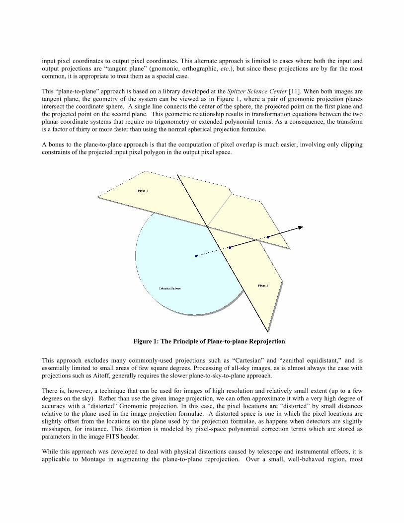
This “plane-to-plane” approach is based on a library developed at the Spitzer Science Center [11]. When both images aretangent plane, the geometry of the system can be viewed as in Figure 1, where a pair of gnomonic projection planesintersect the coordinate sphere. A single line connects the center of the sphere, the projected point on the first plane andthe projected point on the second plane. This geometric relationship results in transformation equations between the twoplanar coordinate systems that require no trigonometry or extended polynomial terms. As a consequence, the transformis a factor of thirty or more faster than using the normal spherical projection formulae.
A bonus to the plane-to-plane approach is that the computation of pixel overlap is much easier, involving only clippingconstraints of the projected input pixel polygon in the output pixel space.
Figure 1: The Principle of Plane-to-plane Reprojection
This approach excludes many commonly-used projections such as “Cartesian” and “zenithal equidistant,” and isessentially limited to small areas of few square degrees. Processing of all-sky images, as is almost always the case withprojections such as Aitoff, generally requires the slower plane-to-sky-to-plane approach.
There is, however, a technique that can be used for images of high resolution and relatively small extent (up to a fewdegrees on the sky). Rather than use the given image projection, we can often approximate it with a very high degree ofaccuracy with a “distorted” Gnomonic projection. In this case, the pixel locations are “distorted” by small distancesrelative to the plane used in the image projection formulae. A distorted space is one in which the pixel locations areslightly offset from the locations on the plane used by the projection formulae, as happens when detectors are slightlymisshapen, for instance. This distortion is modeled by pixel-space polynomial correction terms which are stored asparameters in the image FITS header.
While this approach was developed to deal with physical distortions caused by telescope and instrumental effects, it isapplicable to Montage in augmenting the plane-to-plane reprojection. Over a small, well-behaved region, most
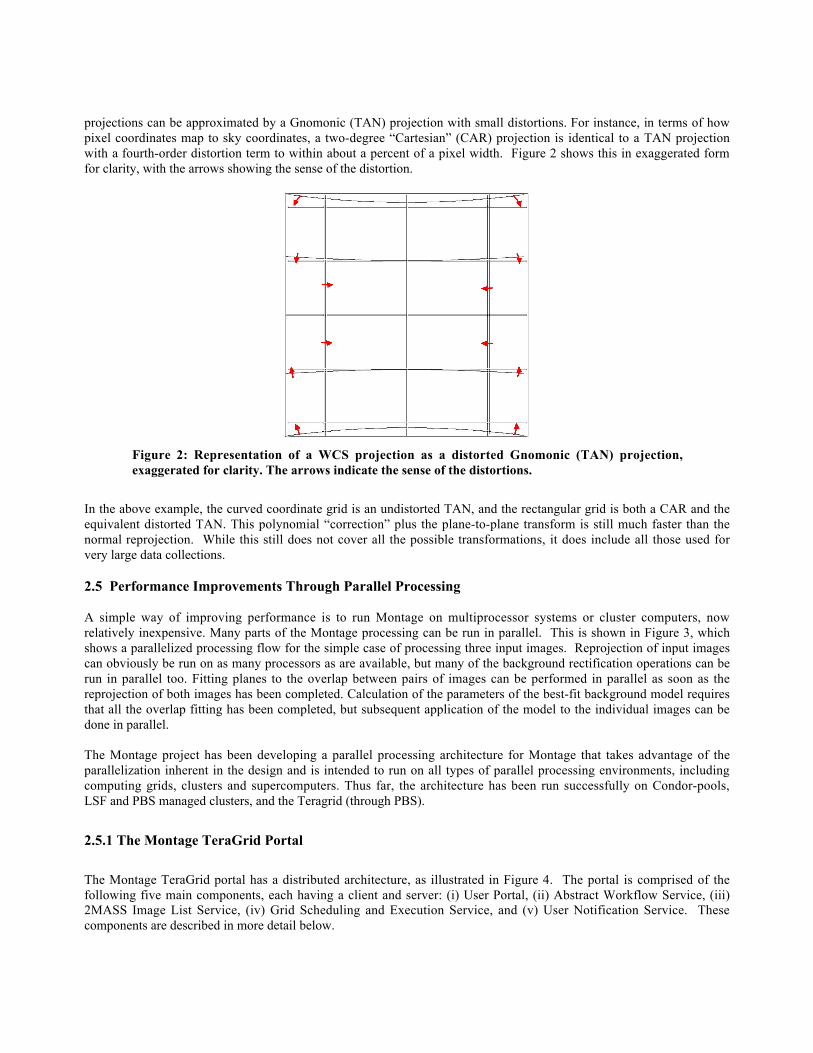
projections can be approximated by a Gnomonic (TAN) projection with small distortions. For instance, in terms of howpixel coordinates map to sky coordinates, a two-degree “Cartesian” (CAR) projection is identical to a TAN projectionwith a fourth-order distortion term to within about a percent of a pixel width. Figure 2 shows this in exaggerated formfor clarity, with the arrows showing the sense of the distortion.
Figure 2: Representation of a WCS projection as a distorted Gnomonic (TAN) projection,exaggerated for clarity. The arrows indicate the sense of the distortions.
In the above example, the curved coordinate grid is an undistorted TAN, and the rectangular grid is both a CAR and theequivalent distorted TAN. This polynomial “correction” plus the plane-to-plane transform is still much faster than thenormal reprojection. While this still does not cover all the possible transformations, it does include all those used forvery large data collections.
2.5 Performance Improvements Through Parallel Processing
A simple way of improving performance is to run Montage on multiprocessor systems or cluster computers, nowrelatively inexpensive. Many parts of the Montage processing can be run in parallel. This is shown in Figure 3, whichshows a parallelized processing flow for the simple case of processing three input images. Reprojection of input imagescan obviously be run on as many processors as are available, but many of the background rectification operations can berun in parallel too. Fitting planes to the overlap between pairs of images can be performed in parallel as soon as thereprojection of both images has been completed. Calculation of the parameters of the best-fit background model requiresthat all the overlap fitting has been completed, but subsequent application of the model to the individual images can bedone in parallel.
The Montage project has been developing a parallel processing architecture for Montage that takes advantage of theparallelization inherent in the design and is intended to run on all types of parallel processing environments, includingcomputing grids, clusters and supercomputers. Thus far, the architecture has been run successfully on Condor-pools,LSF and PBS managed clusters, and the Teragrid (through PBS).
2.5.1 The Montage TeraGrid Portal
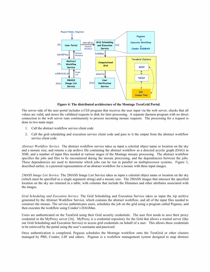
The Montage TeraGrid portal has a distributed architecture, as illustrated in Figure 4. The portal is comprised of thefollowing five main components, each having a client and server: (i) User Portal, (ii) Abstract Workflow Service, (iii)2MASS Image List Service, (iv) Grid Scheduling and Execution Service, and (v) User Notification Service. Thesecomponents are described in more detail below.
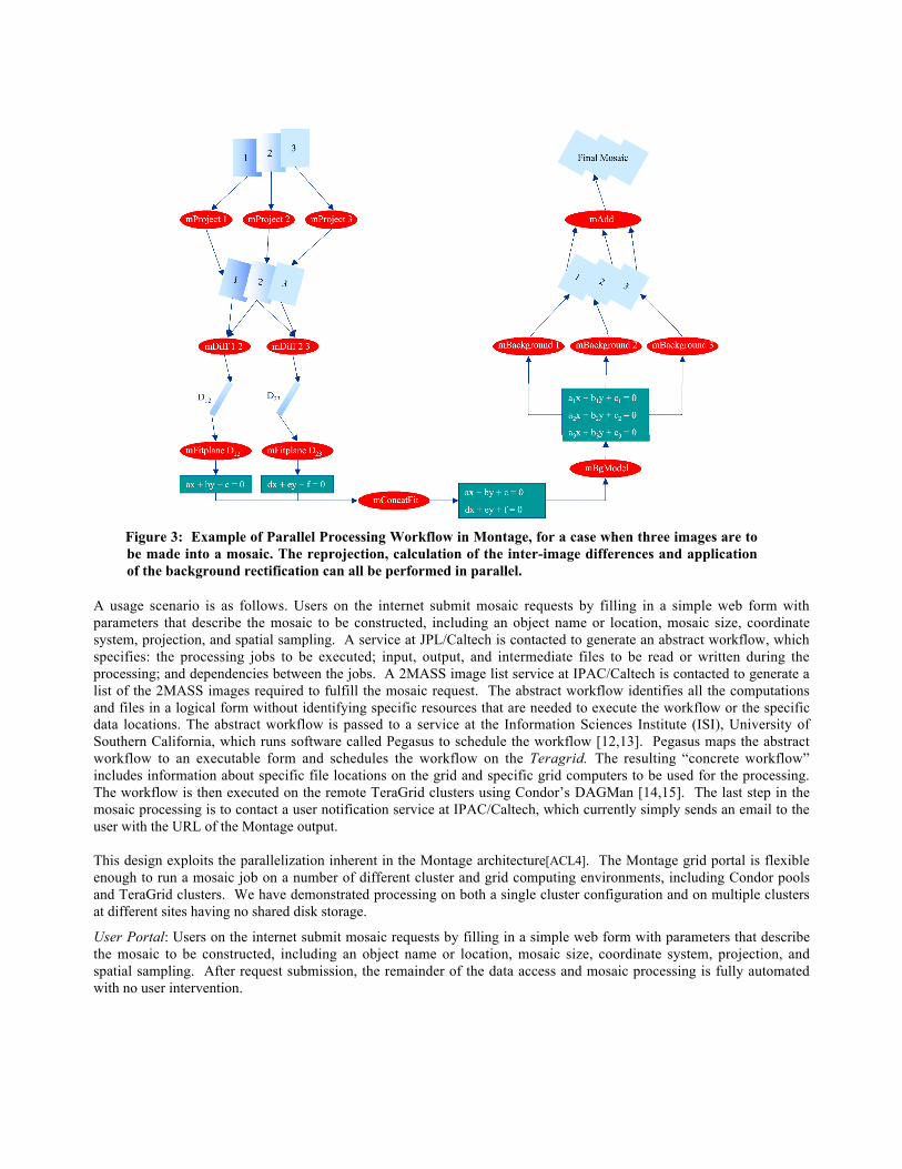
Figure 3: Example of Parallel Processing Workflow in Montage, for a case when three images are tobe made into a mosaic. The reprojection, calculation of the inter-image differences and applicationof the background rectification can all be performed in parallel.
A usage scenario is as follows. Users on the internet submit mosaic requests by filling in a simple web form withparameters that describe the mosaic to be constructed, including an object name or location, mosaic size, coordinatesystem, projection, and spatial sampling. A service at JPL/Caltech is contacted to generate an abstract workflow, whichspecifies: the processing jobs to be executed; input, output, and intermediate files to be read or written during theprocessing; and dependencies between the jobs. A 2MASS image list service at IPAC/Caltech is contacted to generate alist of the 2MASS images required to fulfill the mosaic request. The abstract workflow identifies all the computationsand files in a logical form without identifying specific resources that are needed to execute the workflow or the specificdata locations. The abstract workflow is passed to a service at the Information Sciences Institute (ISI), University ofSouthern California, which runs software called Pegasus to schedule the workflow [12,13]. Pegasus maps the abstractworkflow to an executable form and schedules the workflow on the Teragrid. The resulting “concrete workflow”includes information about specific file locations on the grid and specific grid computers to be used for the processing.The workflow is then executed on the remote TeraGrid clusters using Condor’s DAGMan [14,15]. The last step in themosaic processing is to contact a user notification service at IPAC/Caltech, which currently simply sends an email to theuser with the URL of the Montage output.
This design exploits the parallelization inherent in the Montage architecture[ACL4]. The Montage grid portal is flexibleenough to run a mosaic job on a number of different cluster and grid computing environments, including Condor poolsand TeraGrid clusters. We have demonstrated processing on both a single cluster configuration and on multiple clustersat different sites having no shared disk storage.
User Portal: Users on the internet submit mosaic requests by filling in a simple web form with parameters that describethe mosaic to be constructed, including an object name or location, mosaic size, coordinate system, projection, andspatial sampling. After request submission, the remainder of the data access and mosaic processing is fully automatedwith no user intervention.
Region Name, Degrees
Pegasus
Concrete Workflow
Condor DAGMAN
TeraGrid Clusters
SDSC
NCSA
ISI Condor Pool
AbstractWorkflow
User Portal
AbstractWorkflowService
2MASSImage ListService
Grid Schedulingand Execution
Service
UserNotification
Service
ComputationalGrid
mDAGFiles
m2MASSList
mGridExec
ImageList
DAGMan
mNotify
JPL
JPL
IPAC IPAC
ISIAbstractWorkflow
Figure 4: The distributed architecture of the Montage TeraGrid Portal.
The server side of the user portal includes a CGI program that receives the user input via the web server, checks that allvalues are valid, and stores the validated requests to disk for later processing. A separate daemon program with no directconnection to the web server runs continuously to process incoming mosaic requests. The processing for a request isdone in two main steps:
1. Call the abstract workflow service client code
2. Call the grid scheduling and execution service client code and pass to it the output from the abstract workflowservice client code
Abstract Workflow Service. The abstract workflow service takes as input a celestial object name or location on the skyand a mosaic size, and returns a zip archive file containing the abstract workflow as a directed acyclic graph (DAG) inXML and a number of input files needed at various stages of the Montage mosaic processing. The abstract workflowspecifies the jobs and files to be encountered during the mosaic processing, and the dependencies between the jobs.These dependencies are used to determine which jobs can be run in parallel on multiprocessor systems. Figure 3,described earlier, is a pictorial representation of an abstract workflow for a mosaic with three input images.
2MASS Image List Service. The 2MASS Image List Service takes as input a celestial object name or location on the sky(which must be specified as a single argument string) and a mosaic size. The 2MASS images that intersect the specifiedlocation on the sky are returned in a table, with columns that include the filenames and other attributes associated withthe images.
Grid Scheduling and Execution Service. The Grid Scheduling and Execution Service takes as input the zip archivegenerated by the Abstract Workflow Service, which contains the abstract workflow, and all of the input files needed toconstruct the mosaic. The service authenticates users, schedules the job on the grid using a program called Pegasus, andthen executes the workflow using Condor’s DAGMan.
Users are authenticated on the TeraGrid using their Grid security credentials. The user first needs to save their proxycredential in the MyProxy server [16]. MyProxy is a credential repository for the Grid that allows a trusted server (likeour Grid Scheduling and Execution Service) to access grid credentials on behalf of a user. This allows these credentialsto be retrieved by the portal using the user’s username and password.
Once authentication is completed, Pegasus schedules the Montage workflow onto the TeraGrid or other clustersmanaged by PBS, Condor, LSF and others. Pegasus is a workflow management system designed to map abstract

workflows onto the grid resources to produce concrete (executable) workflows. The Metadata Catalog Service (MCS)[17] keeps track of the mosaics produced. Pegasus consults various Grid information services, such as the GlobusMonitoring and Discovery Service (MDS) [18] to discover which compute resources are available, the Globus ReplicaLocation Service (RLS) [19] to discover data locations, and the Transformation Catalog [20] to determine where theMontage executable images are installed. Pegasus reduces the abstract workflow by pruning those workflow productsthat are already registered in the RLS. The executable workflow generated by Pegasus specifies the grid computers to beused, the data movement for staging data in and out of the computation, and the data products to be registered in the RLSand MCS.
The executable workflow is submitted to Condor’s DAGMan for execution. DAGMan is a scheduler that submits jobs toCondo-G in the order specified by the concrete workflow. Condor-G queues the jobs for execution on the TeraGrid.Upon completion, the final mosaic is delivered to a user-specified location, and the User Notification Service, describedbelow, is contacted.
User Notification Service. The last step in the grid processing is to notify the user of the URL where the mosaic may bedownloaded. This notification is performed by a remote user notification service at Caltech, IPAC, so that a newnotification mechanism can be used later without having to modify the Grid Scheduling and Execution Service.Currently the user notification is performed with a simple email, but a later version will use the Request ObjectManagement Environment (ROME), being developed separately for the National Virtual Observatory. ROME willextend our portal with more sophisticated job monitoring, query, and notification capabilities.
2.5.2 Performance of the Montage Teragrid Portal
Table 1 gives the runtimes of the individual workflow components to summarize the results of running a 2-degree M16mosaic on the NCSA TeraGrid cluster. These performance figures apply to the processing modules in version 1.7.x ofMontage, which does not include the algorithmic optimizations described in Sections 2.3 and 2.4 The total runtime ofthe workflow was 107 minutes, and the workflow contained 1,515 individual jobs.
Our main goal was to demonstrate the feasibility of running the Montage workflow in an automated fashion on theTeraGrid with some amount of performance improvement over the sequential version. Currently, Pegasus schedules theworkflow as a set of small jobs. As seen in the table, some of these jobs run in only a few seconds, which is suboptimalbecause scheduling too many little jobs suffers from large overheads. These overheads stem from the resourceschedulers that queue incoming jobs and the time that a job spends in the queue. In fact, if this processing was run on asingle TeraGrid processor, it would have taken 445 minutes, so we are not taking very much advantage of the TeraGrid’sparallelism. However, initially structuring the workflow in this way allows us to expose the highest degree ofparallelism.
TABLE 1: TERAGRID PERFORMANCE OF MONTAGE
Numberof Jobs Job Name Average Run-Time
1 mAdd 94.00 seconds180 mBackground 2.64 seconds1 mBgModel 11 seconds1 mConcatFit 9 seconds482 mDiff 2.89 seconds483 mFitplane 2.55 seconds180 mProject 130.52 seconds
183 Transfer of data in Between 5-30 seconds each1 Transfer of mosaic out 18: 03 minutes
We will improve this performance by optimizing both the Montage algorithms and the grid scheduling techniques. Weexpect about a 30 times speedup without sacrificing accuracy by using the algorithmic techniques described in Section2.4. We will address the Teragrid performance in three ways: making Pegasus aggregate nodes in the workflow in away that would reduce the overheads for given target systems; encouraging the Condor developers to reduce the per-joboverhead; and examining alternate methods for distributing the work on the grid. Each option has advantages anddisadvantages that will be weighed as we go forward.
3. SCIENTIFIC APPLICATIONS
The Montage software is available through a free, “clickwrap” license issued by the California Institute of Technology.Version 1.7 is publicly accessible, and Version 2.0 is currently available for evaluation on a shared risk basis. Thesoftware is finding broad applicability in astronomical research and in Education and Public Outreach.
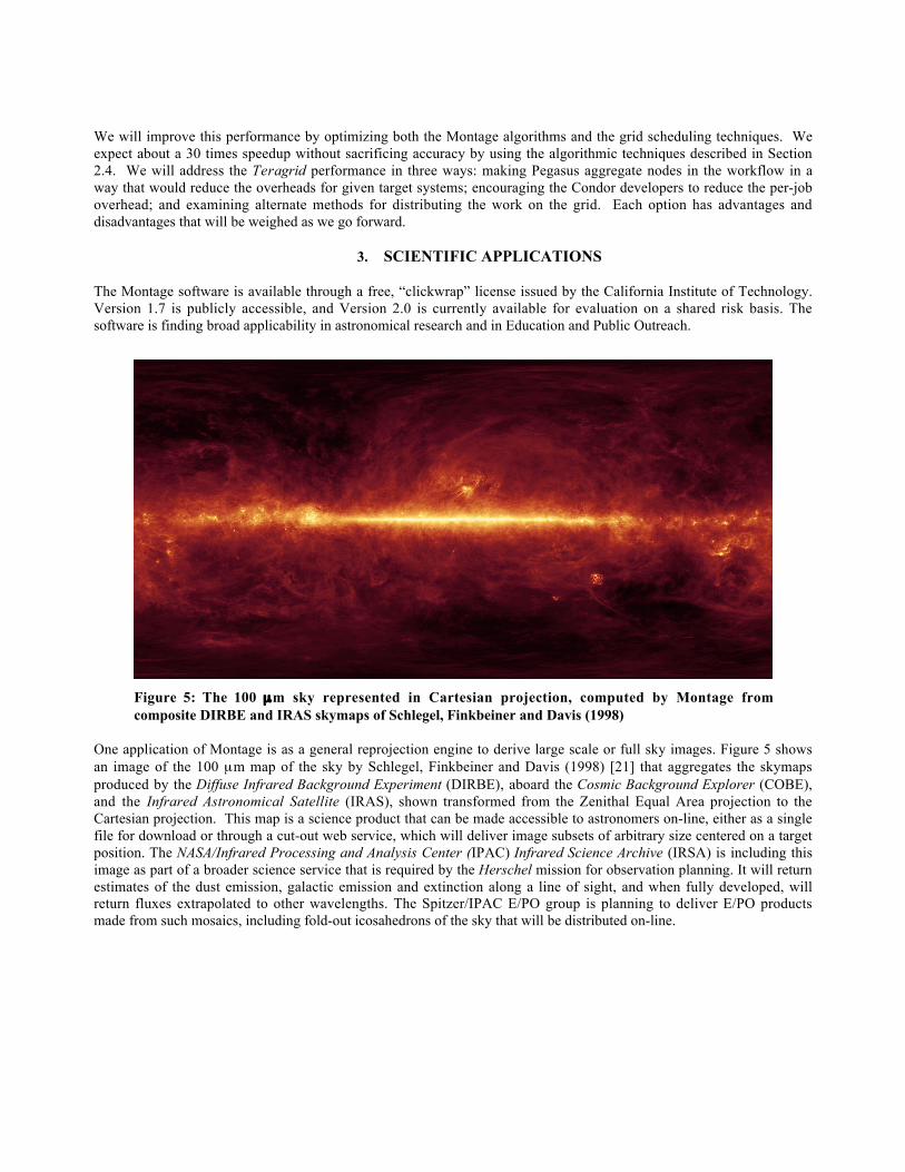
Figure 5: The 100 µm sky represented in Cartesian projection, computed by Montage fromcomposite DIRBE and IRAS skymaps of Schlegel, Finkbeiner and Davis (1998)
One application of Montage is as a general reprojection engine to derive large scale or full sky images. Figure 5 showsan image of the 100 µm map of the sky by Schlegel, Finkbeiner and Davis (1998) [21] that aggregates the skymapsproduced by the Diffuse Infrared Background Experiment (DIRBE), aboard the Cosmic Background Explorer (COBE),and the Infrared Astronomical Satellite (IRAS), shown transformed from the Zenithal Equal Area projection to theCartesian projection. This map is a science product that can be made accessible to astronomers on-line, either as a singlefile for download or through a cut-out web service, which will deliver image subsets of arbitrary size centered on a targetposition. The NASA/Infrared Processing and Analysis Center (IPAC) Infrared Science Archive (IRSA) is including thisimage as part of a broader science service that is required by the Herschel mission for observation planning. It will returnestimates of the dust emission, galactic emission and extinction along a line of sight, and when fully developed, willreturn fluxes extrapolated to other wavelengths. The Spitzer/IPAC E/PO group is planning to deliver E/PO productsmade from such mosaics, including fold-out icosahedrons of the sky that will be distributed on-line.
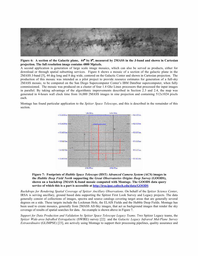
Figure 6: A section of the Galactic plane, 44° by 8°, measured by 2MASS in the J-band and shown in Cartesianprojection. The full resolution image contains 4800 Mpixels.A second application is generation of large scale image mosaics, which can also be served as products, either fordownload or through spatial subsetting services. Figure 6 shows a mosaic of a section of the galactic plane in the2MASS J-band [5], 44 deg long and 8 deg wide, centered on the Galactic Center and shown in Cartesian projection. Theproduction of this mosaic was intended as a pilot project to provide resource estimates for generation of a full-sky2MASS mosaic, to be computed on the San Diego Supercomputer Center’s IBM DataStar supercomputer, when fullycommissioned. The mosaic was produced on a cluster of four 1.4 Ghz Linux processors that processed the input imagesin parallel. By taking advantage of the algorithmic improvements described in Section 2.3 and 2.4, the map wasgenerated in 4-hours wall clock time from 16,000 2MASS images in sine projection and containing 512x1024 pixelseach.
Montage has found particular application to the Spitzer Space Telescope, and this is described in the remainder of thissection.
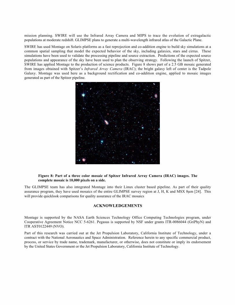
Figure 7: Footprints of Hubble Space Telescope (HST) Advanced Camera System (ACS) images inthe Hubble Deep Field North supporting the Great Observatories Origins Deep Survey (GOODS),shown on a backdrop 2MASS K-band mosaic computed with Montage. The GOODS data queryservice of which this is a part is accessible at http://irsa.ipac.caltech.edu/data/GOODS
Backdrops for Rendering Spatial Coverage of Spitzer Ancillary Observations. On behalf of the Spitzer Science Center,IRSA is serving ancillary, ground based data supporting the Spitzer First Look Survey and Legacy projects. The datagenerally consist of collections of images, spectra and source catalogs covering target areas that are generally severaldegrees on a side. These targets include the Lockman Hole, the ELAIS Fields and the Hubble Deep Fields. Montage hasbeen used to create mosaics, generally from 2MASS All-Sky images, that act as background images that render the skycoverage of results of spatial searches for data. An example is shown above in Figure 7.
Support for Data Production and Validation by Spitzer Space Telescope Legacy Teams. Two Spitzer Legacy teams, theSpitzer Wide-area InfraRed Extragalactic (SWIRE) survey [22] and the Galactic Legacy Infrared Mid-Plane SurveyExtraordinaire (GLIMPSE) [23], are actively using Montage to support their processing pipelines, quality assurance and
mission planning. SWIRE will use the Infrared Array Camera and MIPS to trace the evolution of extragalacticpopulations at moderate redshift. GLIMPSE plans to generate a multi-wavelength infrared atlas of the Galactic Plane.
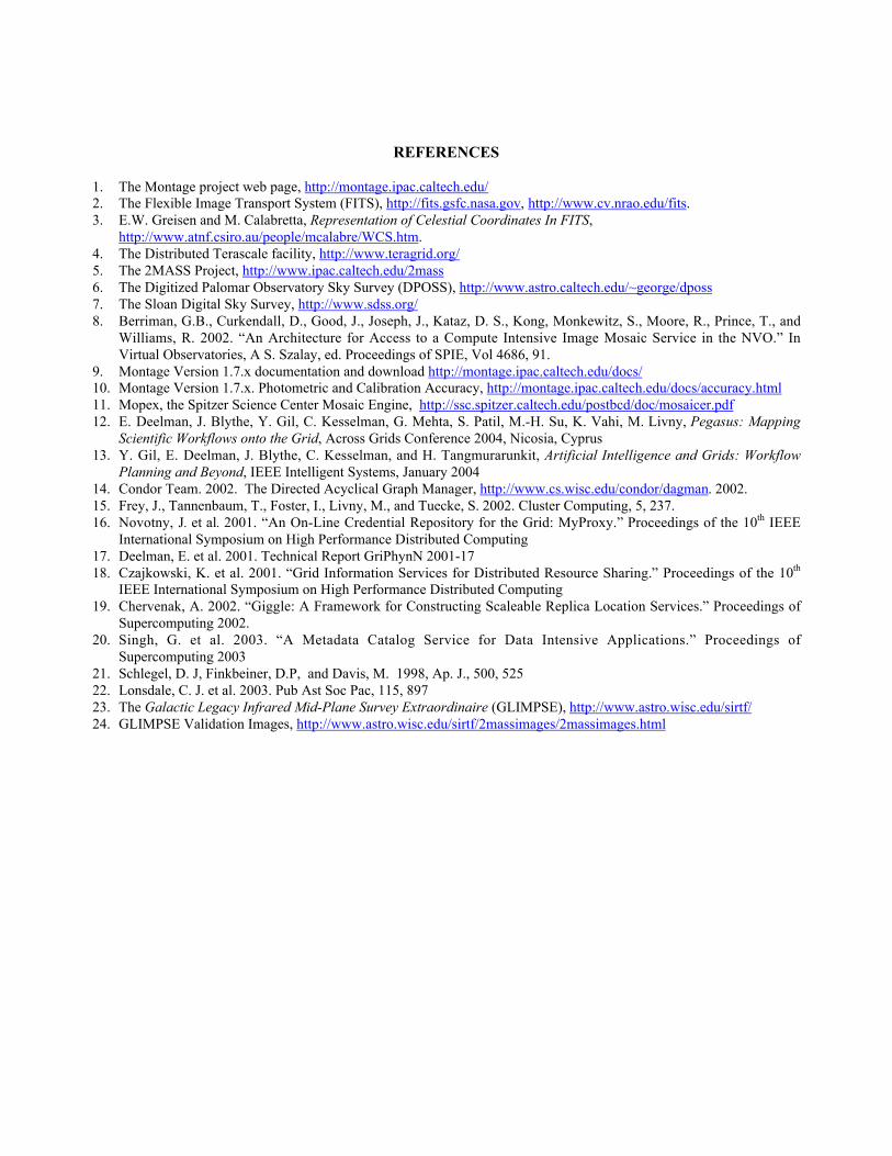
SWIRE has used Montage on Solaris platforms as a fast reprojection and co-addition engine to build sky simulations at acommon spatial sampling that model the expected behavior of the sky, including galaxies, stars and cirrus. Thesesimulations have been used to validate the processing pipeline and source extraction. Predictions of the expected sourcepopulations and appearance of the sky have been used to plan the observing strategy. Following the launch of Spitzer,SWIRE has applied Montage to the production of science products. Figure 8 shows part of a 2.5 GB mosaic generatedfrom images obtained with Spitzer’s Infrared Array Camera (IRAC); the bright galaxy left of center is the TadpoleGalaxy. Montage was used here as a background rectification and co-addition engine, applied to mosaic imagesgenerated as part of the Spitzer pipeline.
Figure 8: Part of a three color mosaic of Spitzer Infrared Array Camera (IRAC) images. Thecomplete mosaic is 10,000 pixels on a side.
The GLIMPSE team has also integrated Montage into their Linux cluster based pipeline. As part of their qualityassurance program, they have used mosaics of the entire GLIMPSE survey region at J, H, K and MSX 8µm [24]. Thiswill provide quicklook comparisons for quality assurance of the IRAC mosaics
ACKNOWLEDGEMENTS
Montage is supported by the NASA Earth Sciences Technology Office Computing Technologies program, underCooperative Agreement Notice NCC 5-6261. Pegasus is supported by NSF under grants ITR-0086044 (GriPhyN) andITR AST0122449 (NVO).
Part of this research was carried out at the Jet Propulsion Laboratory, California Institute of Technology, under acontract with the National Aeronautics and Space Administration. Reference herein to any specific commercial product,process, or service by trade name, trademark, manufacturer, or otherwise, does not constitute or imply its endorsementby the United States Government or the Jet Propulsion Laboratory, California Institute of Technology.
REFERENCES
1. The Montage project web page, http://montage.ipac.caltech.edu/2. The Flexible Image Transport System (FITS), http://fits.gsfc.nasa.gov, http://www.cv.nrao.edu/fits.3. E.W. Greisen and M. Calabretta, Representation of Celestial Coordinates In FITS,
http://www.atnf.csiro.au/people/mcalabre/WCS.htm.4. The Distributed Terascale facility, http://www.teragrid.org/5. The 2MASS Project, http://www.ipac.caltech.edu/2mass6. The Digitized Palomar Observatory Sky Survey (DPOSS), http://www.astro.caltech.edu/~george/dposs7. The Sloan Digital Sky Survey, http://www.sdss.org/8. Berriman, G.B., Curkendall, D., Good, J., Joseph, J., Kataz, D. S., Kong, Monkewitz, S., Moore, R., Prince, T., and
Williams, R. 2002. “An Architecture for Access to a Compute Intensive Image Mosaic Service in the NVO.” InVirtual Observatories, A S. Szalay, ed. Proceedings of SPIE, Vol 4686, 91.
9. Montage Version 1.7.x documentation and download http://montage.ipac.caltech.edu/docs/10. Montage Version 1.7.x. Photometric and Calibration Accuracy, http://montage.ipac.caltech.edu/docs/accuracy.html11. Mopex, the Spitzer Science Center Mosaic Engine, http://ssc.spitzer.caltech.edu/postbcd/doc/mosaicer.pdf12. E. Deelman, J. Blythe, Y. Gil, C. Kesselman, G. Mehta, S. Patil, M.-H. Su, K. Vahi, M. Livny, Pegasus: Mapping
Scientific Workflows onto the Grid, Across Grids Conference 2004, Nicosia, Cyprus13. Y. Gil, E. Deelman, J. Blythe, C. Kesselman, and H. Tangmurarunkit, Artificial Intelligence and Grids: Workflow
Planning and Beyond, IEEE Intelligent Systems, January 200414. Condor Team. 2002. The Directed Acyclical Graph Manager, http://www.cs.wisc.edu/condor/dagman. 2002.15. Frey, J., Tannenbaum, T., Foster, I., Livny, M., and Tuecke, S. 2002. Cluster Computing, 5, 237.16. Novotny, J. et al. 2001. “An On-Line Credential Repository for the Grid: MyProxy.” Proceedings of the 10th IEEE
International Symposium on High Performance Distributed Computing17. Deelman, E. et al. 2001. Technical Report GriPhynN 2001-1718. Czajkowski, K. et al. 2001. “Grid Information Services for Distributed Resource Sharing.” Proceedings of the 10th
IEEE International Symposium on High Performance Distributed Computing19. Chervenak, A. 2002. “Giggle: A Framework for Constructing Scaleable Replica Location Services.” Proceedings of
Supercomputing 2002.20. Singh, G. et al. 2003. “A Metadata Catalog Service for Data Intensive Applications.” Proceedings of
Supercomputing 200321. Schlegel, D. J, Finkbeiner, D.P, and Davis, M. 1998, Ap. J., 500, 52522. Lonsdale, C. J. et al. 2003. Pub Ast Soc Pac, 115, 89723. The Galactic Legacy Infrared Mid-Plane Survey Extraordinaire (GLIMPSE), http://www.astro.wisc.edu/sirtf/24. GLIMPSE Validation Images, http://www.astro.wisc.edu/sirtf/2massimages/2massimages.html