Embed Size (px)
Citation preview
ISSN: 2278 - 8875
International Journal of Advanced Research in Electrical, Electronics and Instrumentation Engineering Vol. 1, Issue 4, October 2012
Copyright to IJAREEIE www.ijareeie.com 270
Monitoring of Power Transmission through Cables
Sahad A
M.Tech Student, TKM College of Engineering, Kollam, Kerala, India
Abstract: Power transmission overhead line online monitoring [8] was implemented in some countries. This paper mostly
discussed about the monitoring of power transmission cables. In densely populated cities overhead transmission has a limit.
More over faults are more in overhead transmission due to damage in conductors, birds, temperature, wind and so on.
These drawbacks can be avoided to a large extend through underground cables. If it is monitored real time its power
transmission capability and reliability can also be increased. Even though this is a costliest type of transmission cables, are
adopted in cities. In addition to the underground cables, power cables are used in industry to carry the power from control
station to the site. Cable trenches and cable trays are used for this.
Key words: Power Transmission, Insulation Resistance, Lightning Arrester, Infrared Sensor, Cable trench, Cable tray.
I. INTRODUCTION
Power transmission is tedious task.Generating stations are far located from cities. The generating voltage in India (standard 11kV)
cannot be transmitted as it is. It has to be stepped up for long distance transmission. The factor which is considered are voltage and
distance during transmission. Current is a factor since by Joules law (I)
H= RT………………………….. (I)
Where H is the heat produced, I is the current through the conductor, Resistance of the conductor and T is the time taken through
which power is transmitted.
By analyzing the law (I) heat loss is directly proportional to the square of the current. So current cannot be increased. By the
equation (II) power to be transmitted can be increased by increasing the voltage.
P=3VI (for three phase)…………………….(II)
Where P is the power, V is the voltage, I is the current and is the power factor of the alternating current system.
This power can be increased with more reliability through power transmission cables.3 core and 3 and half core are more common.
Racoon is also one type of cable used in India. Its different parameters can be measured using the techniques discussed below. The
measured parameters (using Power Transducers) can be transmitted using GPRS techniques. These are interfaced to a Personal
Computer for Monitoring.
ISSN: 2278 - 8875
International Journal of Advanced Research in Electrical, Electronics and Instrumentation Engineering Vol. 1, Issue 4, October 2012
Copyright to IJAREEIE www.ijareeie.com 271
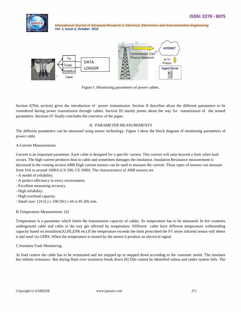
Figure I. Monitoring parameters of power cables.
Section I(This section) gives the introduction of power transmission. Section II describes about the different parameters to be
considered during power transmission through cables. Section III mainly points about the way for transmission of the sensed
parameters. Sections IV finally concludes the overview of the paper.
II. PARAMETER MEASUREMENTS
The different parameters can be measured using sensor technology. Figure I show the block diagram of monitoring parameters of
power cable.
A.Current Measurements.
Current is an important parameter. Each cable is designed for a specific current. This current will raise beyond a limit when fault
occurs. The high current produces heat in cable and sometimes damages the insulation. Insulation Resistance measurement is
discussed in the coming section.ABB High current sensors can be used to measure the current. These types of sensors can measure
from 10A to around 1000A (CS 500, CS 1000). The characteristics of ABB sensors are
- A model of reliability.
- A perfect efficiency in every environment.
- Excellent measuring accuracy.
- High reliability.
- High overload capacity.
- Small size: 124 (L) x 100 (W) x 44 or 81 (H) mm.
B.Temperature Measurement. [4]
Temperature is a parameter which limits the transmission capacity of cables. So temperature has to be measured. In hot countries
underground cable and cable in the tray get affected by temperature. Different cable have different temperature withstanding
capacity based on insulation(XLPE,EPR etc).If the temperature exceeds the limit prescribed the FT series infrared sensor will detect
it and send via GPRS. When the temperature is sensed by the sensor it produce an electrical signal.
C.Insulator Fault Monitoring.
At load centers the cable has to be terminated and are stepped up or stepped down according to the customer needs. The insulator
has infinite resistance. But during flash over insulation break down [8].This cannot be identified unless and under system fails. The
DATA
LOGGER
ISSN: 2278 - 8875
International Journal of Advanced Research in Electrical, Electronics and Instrumentation Engineering Vol. 1, Issue 4, October 2012
Copyright to IJAREEIE www.ijareeie.com 272
breakdown occurred in its internal. The insulator flashover discharge between iron cap and iron pin ceramic, the trace cannot be
seen, but the insulation has been lost, and it may be completely destroyed due to arcing. For breakdown, the discharge traces of iron
legs and burnt situation should be paid great attention. Transmission line insulator flashover [2] in operation can cause blackout
accidents, to affect seriously the power grid stability and reliability. All insulators are affected to some extent by impact, thermal
and mechanical cycling, ablation from weathering and electro-thermal causes, flexure and torsion. ETCR 085K sensors can be used
here. The increase temperature causes the insulation to break down. This produce leakage current which is sensed using sensor
module
The insulation resistance can be formulated as follows. The cable has a sheath of inside radius R.
=
ln
ohms ………………….. (III)
Where is the insulation resistance of the cable, resistivity of the insulating material of the cable, l length of cable and r radius
of the conductor.
Average value of or impregnated paper varies from 5 X to 8 X ohm meters at 15
This sensor embedded in sensor module transmits the data through GPRS network.
D.Lightning Arrester Monitoring
Transformer is important equipment in power transmission system. It is also the costliest ac machines. It is very sensitive to
lightning. So it has to be protected. Also the cables exposed in Cable trenches in various industries are subjected to lightning. In
country like China and Bangladesh it is severe. Thyrite lightning arresters are mostly used in India. The lightning arresters act as
insulators for normal current but act as conducting material during surges. When severe lightning occurs it breakdown and does not
work effectively. During this time it conducts for normal current also. The current sensor(ETCR 080) implemented can also
measure this value. The measured values are send to the servers through GPRS technology [5].
E.Power Cable Visual Monitoring
Substation and Control station are located away from the site equipments. When insulation failed the conductor may get in touch
with cable trench/tray. This will cause damage to the whole system and system gets tripped. The spliced cables also cause problems
if not connected properly. So high sensitive CCD camera (SAA71, FPGA Series) are installed. The digital signal is digitized and
sends through GPRS technology to the control station.
III.PARAMETER TRANSMISSION
Smart system for the meteorological monitoring of transmission line based on ZigBee and General Packet Radio Service
(GPRS)[6][7] technology was developed in order to overcome the shortcomings of the present system, such as the totally
dependence on the limited coverage of communication network, the single monitoring parameters and the poor extensibility, etc.
SHT10 integrates the sensing element and signal processing circuit in a micro-circuit board. It has output of standardized digital
signal, small size and low power consumption. The system in this paper has the advantages of low power consumption, low node
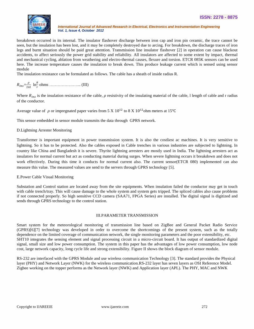
cost, large network capacity, long cycle life and strong extensibility. Figure II shows the block diagram of sensor module.
RS-232 are interfaced with the GPRS Module and use wireless communication Technology [3]. The standard provides the Physical
layer (PHY) and Network Layer (NWK) for the wireless communication.RS-232 layer has seven layers as OSI Reference Model.
Zigbee working on the topper performs as the Network layer (NWK) and Application layer (APL). The PHY, MAC and NWK
ISSN: 2278 - 8875
International Journal of Advanced Research in Electrical, Electronics and Instrumentation Engineering Vol. 1, Issue 4, October 2012
Copyright to IJAREEIE www.ijareeie.com 273
layers handle the data transmission and the APL layer handles the tasks of each device. CC2430 made by TI (Texas Instruments)
was used as MCU and RF module. The chip is chosen to implement the chip system on embedded ZigBee applications.
GPRS is a GSM-based wireless packet technology. It provides wide-area wireless IP connection by a kind of point to point way.
GPRS is a high-speed data-processing technology, for which data are transmitted in the form of "group"[3]. It has the following
characteristics: first, it will remain online as long as GPRS is applied; second, GPRS only charges when it generates communication
flow; third, the current GPRS can support the peak rate of 53.6Kbps while theoretical transferring peak reaches more than 100
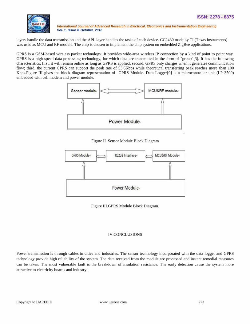
Kbps.Figure III gives the block diagram representation of GPRS Module. Data Logger[9] is a microcontroller unit (LP 3500)
embedded with cell modem and power module.
Figure II. Sensor Module Block Diagram
Figure III.GPRS Module Block Diagram.
IV.CONCLUSIONS
Power transmission is through cables in cities and industries. The sensor technology incorporated with the data logger and GPRS
technology provide high reliability of the system. The data received from the module are processed and instant remedial measures
can be taken. The most vulnerable fault is the breakdown of insulation resistance. The early detection cause the system more
attractive to electricity boards and industry.
ISSN: 2278 - 8875
International Journal of Advanced Research in Electrical, Electronics and Instrumentation Engineering Vol. 1, Issue 4, October 2012
Copyright to IJAREEIE www.ijareeie.com 274
ACKNOWLEDGEMENTS
I am highly indebted to Dr.J.Abdul Jaleel, Mrs. Jubairiyath Beevi and all other Faculty members in Electrical and Electronics
department of TKM College of Engineering, Kollam, India for their valuable support.
REFERENCES
[1] J.S.T. Looms, “Insulators for High Voltages, Peter Peregrinus Ltd”, 1988.
[2]R.K. Aggarwal , A.T. Johns, J.A.S.B. Jayasinghe, W. Su “An overview of the condition monitoring of overhead lines “Electric
Power Systems Research 53 (2000) 15–22 1988.
[3]Yang Yang, Guangzhong Xie, Xiangdong Xu, Yadong Jiang “A Monitoring System Design in Transmission Lines based on
Wireless Sensor Networks” Procedia 00 (2011) 000–000192 – 199 ICSGCE 2011: 27–30 September 2011, Chengdu, China.
[4] Zhang Gang, “Study on Electrical Switching Device Junction Temperature Monitoring System Based on ZigBee
Technology,” 2010 International Conference on Computer Application and System Modeling (ICCASM 2010)
[5] Christos Xenakis, Danae Apostolopoulou, Angeliki Panou, Ioannis Stavrakakis, “A Qualitative Risk Analysis for the GPRS
Technology,” 2008 IEEE/IFIP International Conference on Embedded and Ubiquitous Computing
[6] Aryadevi Remanidevi Devidas, Maneesha Vinodini Ramesh, “Wireless Smart Grid Design for Monitoring and
Optimizing Electric Transmission in India,” 2010 Fourth International Conference on Sensor Technologies and Applications
[7] Degang Gan, Fan Liu, Lin Du, Yuming Liu, “Research and Implementation of On-line Monitoring Techniques for High Voltage
Equipments in Smart Grid,” High Voltage Engineering and Application (ICHVE), 2010 International Conference on 11-14 Oct.
2010
[8] YANG Qi-ping, XU Dan-feng Li Meng-qun “Development of an Power Transmission Line Online Monitoring System” IEEE
2011.
[9] Rezaei, H.F.; Sitter, N.; Kruger, A.”Next generation system for realtime monitoring of rainfall,soil moisture and soil
temperature”IEEE Symposium on sensors .Publication Year: 2011 , Page(s): 70 - 75
BIOGRAPHY
Sahad A received the B.Tech Degree (Electrical and Electronics) from Muslim Association College of Engineering, Trivandrum on
2007.He worked as Electrical Engineer in Saudi Arabia from January 2008 to October 2009.Later he joined Mohandas College of
Engineering,Trivandrum and worked as Lecturer in Electrical Engineering till Aug 2011.Currently he is doing M.Tech (Electrical
and Electronics-Industrial Instrumentation and Control) in TKM College of Engineering,Kollam.