Embed Size (px)
Citation preview
Power & Control CablesUo/U 0.6/1 kV - IEC 60502-1

2 KERPEN GmbH & Co. KG • 07.2005 • Printing errors excepted. Subject to alteration
© KERPEN GmbH & Co. KG • 07.2005 • Printing errors excepted. Subject to alteration A1
List of Contents
Introduction Page B1
Construction Page B3 Use Page B4
Section 1 PVC-Insulated Low Voltage Cables U0/U 0.6/1 kV (70 °C) unarmoured, flame retardant KERPEN Type: YY-fl 2, 3, 4 and 5-cores Page C2 multicores Page C6
round steel wire armoured, flame retardant KERPEN Type: YYRY-fl 2, 3, 4-cores Page C8 multicores Page C12
Section 2 XLPE-Insulated Low Voltage Cables U0/U 0.6/1 kV (90 °C) unarmoured, flame retardant KERPEN Type: 2XY-fl 2, 3, 4 and 5-cores Page D2 multicores Page D6 round steel wire armoured, flame retardant KERPEN Type: 2XYRY-fl 2, 3, 4-cores Page D8 multicores Page D12
Section 3 Zero Halogen Low Voltage Cables U0/U 0.6/1 kV (90 °C) unarmoured, flame retardant KERPEN Type: 2XH 2, 3, 4 and 5-cores Page E2 multicores Page E6 round steel wire armoured, flame retardant KERPEN Type: 2XHRH 2, 3, 4-cores Page E8 multicores Page E12
Section 4 Zero Halogen Low Voltage Cables U0/U 0.6/1 kV (90 °C) unarmoured, fire resistant & flame retardant KERPEN Type: 2XH 2, 3, 4 and 5-cores Page F2 multicores Page F4 round steel wire armoured, fire resistant & flame retardant KERPEN Type: 2XHRH 2, 3, 4-cores Page F6 multicores Page F8
Section 5 Additional Cable Variations U0/U 0.6/1 kV armoured, flame retardant Description of various cable types Page G3
...
A2 KERPEN GmbH & Co. KG • 07.2005 • Printing errors excepted. Subject to alteration
A2
Appendix
I - Additional Electrical Data
Table 1: Resistance Page H2 Table 2: Reactance Page H3 Table 3: Voltage drop Page H4 Table 4: Current ratings (laid in air) Page H5 Table 5: Current ratings (laid in ground) Page H6 Table 6: Current ratings (laid in single way ducts) Page H7
II - Tests on Power and Control Cables
Table 7: Table of different Tests (Routine-, Sample- and Type-Tests Page H8
III - General Information
Table 8: Comparison AWG sizes - Metric sizes Page H9 Table 9: Cable Abbreviations Page H11 Cable Programme Page H12
Weights, measurements, and properties are approximate.While every care is taken to ensure that the information contained in this publication is correct, no legal responsibility can be accepted for any inaccuracy. The Company reserves the right to alter or modify the information contained herein at any time in the light of technical or other development.
Note: KERPEN GmbH & Co. KG can not be held responsible in any form for any information derived out of this publication.
Issue 20050720
© KERPEN GmbH & Co. KG • 07.2005 • Printing errors excepted. Subject to alteration B1
About this Catalogue
This catalogue contains Power and Control cables designed to IEC 60502-1
The purpose of this catalogue is to provide information on power and control cables used in applications for the international project business. Due to today’s global thinking, the many different local specifications are not practical anymore. A plant is very often designed in one country for a customer in another country - very likely on another continent.
Most countries have their own cable factories for power cables, mostly in cable constructions to their local standards for power distribution. This catalogue is not intended to compete with these applications, although the constructions are suitable.
IEC 60502-1 helps the engineers to design with a practical standard and rules which are applicable and acceptable around the world. Engineers will understand each other, being able to use to the same standard; a plant, once engineered, can be rebuilt in another country, without having to re-engineer the cable section.
Global thinking - justified, of course, and driven by overall cost saving is what we, as a manufacturer, are bound to support. Fortunately, IEC 60502-1 is a standard which is already used as a common basis for many international projects. More and more end-users have already changed - or are accepting -IEC 60502-1 for their current and future projects.
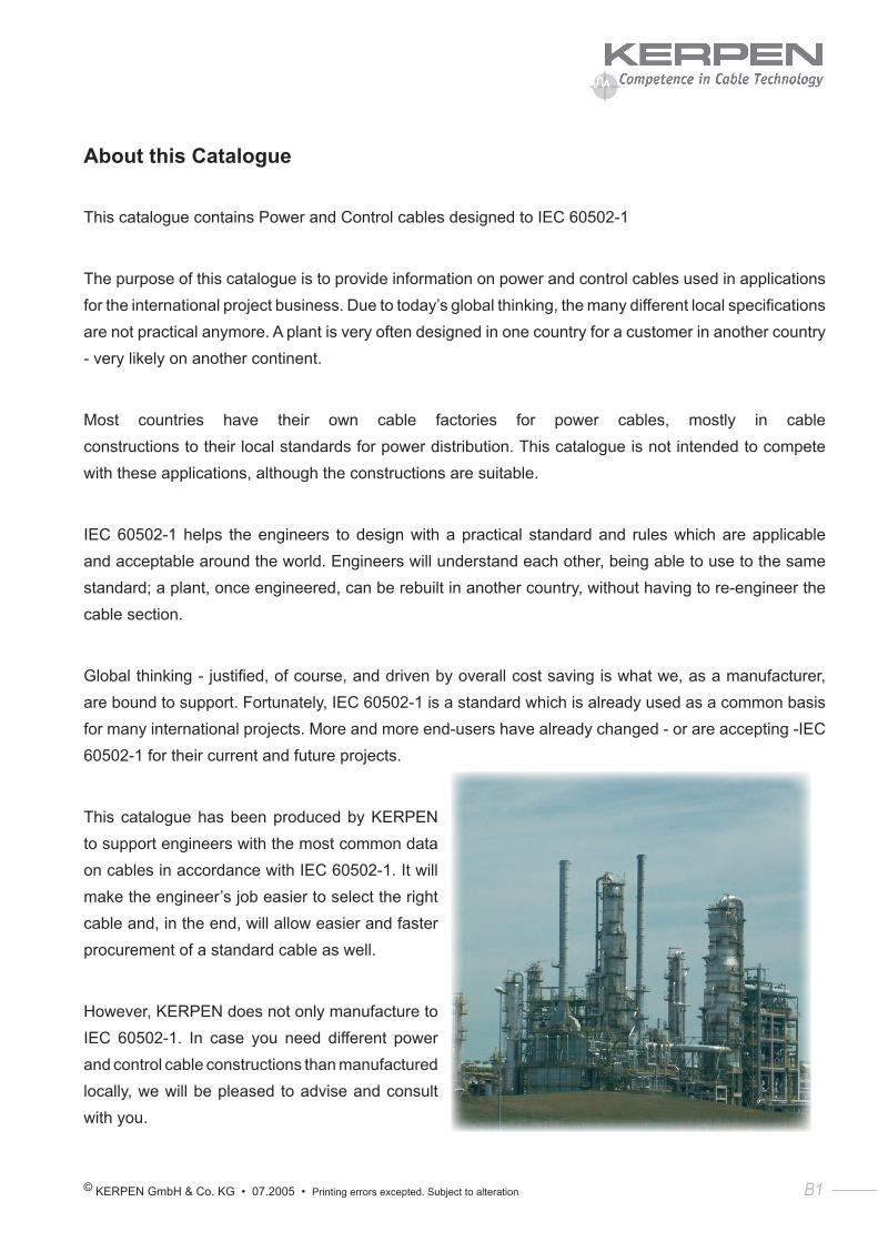
This catalogue has been produced by KERPEN to support engineers with the most common data on cables in accordance with IEC 60502-1. It will make the engineer’s job easier to select the right cable and, in the end, will allow easier and faster procurement of a standard cable as well.
However, KERPEN does not only manufacture to IEC 60502-1. In case you need different power and control cable constructions than manufactured locally, we will be pleased to advise and consult with you.
B2 KERPEN GmbH & Co. KG • 07.2005 • Printing errors excepted. Subject to alteration
B2
1. Introduction
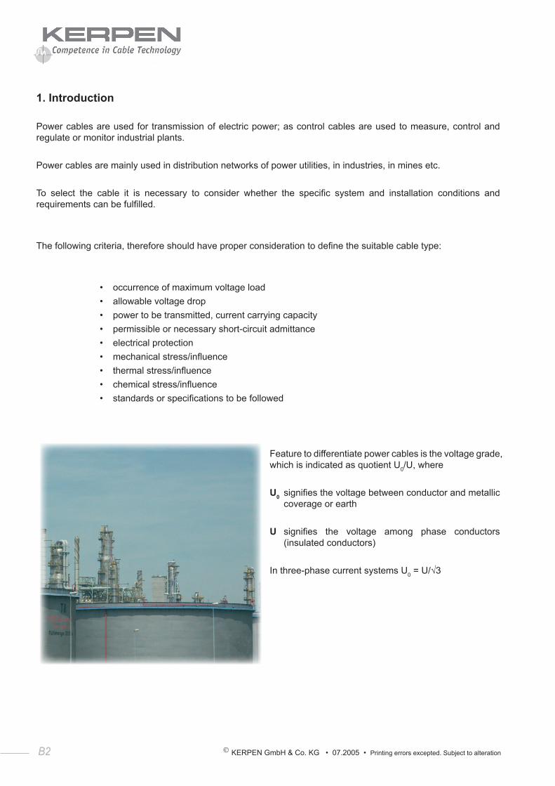
Power cables are used for transmission of electric power; as control cables are used to measure, control and regulate or monitor industrial plants.
Power cables are mainly used in distribution networks of power utilities, in industries, in mines etc.
To select the cable it is necessary to consider whether the specific system and installation conditions and requirements can be fulfilled.
The following criteria, therefore should have proper consideration to define the suitable cable type:
• occurrence of maximum voltage load• allowable voltage drop• power to be transmitted, current carrying capacity• permissible or necessary short-circuit admittance• electrical protection• mechanical stress/influence• thermal stress/influence• chemical stress/influence• standards or specifications to be followed
Feature to differentiate power cables is the voltage grade, which is indicated as quotient U0/U, where
U0 signifies the voltage between conductor and metallic coverage or earth
U signifies the voltage among phase conductors (insulated conductors)
In three-phase current systems U0 = U/√3
© KERPEN GmbH & Co. KG • 07.2005 • Printing errors excepted. Subject to alteration B3
2. Construction
2.1 Conductor
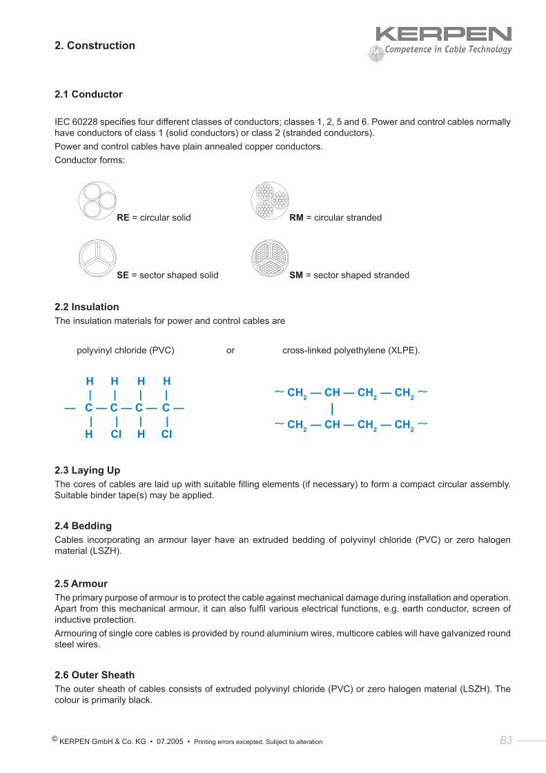
IEC 60228 specifies four different classes of conductors; classes 1, 2, 5 and 6. Power and control cables normally have conductors of class 1 (solid conductors) or class 2 (stranded conductors).Power and control cables have plain annealed copper conductors.Conductor forms:
RE = circular solid RM = circular stranded
SE = sector shaped solid SM = sector shaped stranded
2.2 InsulationThe insulation materials for power and control cables are
polyvinyl chloride (PVC) or cross-linked polyethylene (XLPE).
H H H H | | | | — C — C — C — C — | | | | H CI H CI
∼ CH2 — CH — CH2 — CH2 ∼ |∼ CH2 — CH — CH2 — CH2 ∼
2.3 Laying UpThe cores of cables are laid up with suitable filling elements (if necessary) to form a compact circular assembly. Suitable binder tape(s) may be applied.
2.4 BeddingCables incorporating an armour layer have an extruded bedding of polyvinyl chloride (PVC) or zero halogen material (LSZH).
2.5 ArmourThe primary purpose of armour is to protect the cable against mechanical damage during installation and operation. Apart from this mechanical armour, it can also fulfil various electrical functions, e.g. earth conductor, screen of inductive protection.Armouring of single core cables is provided by round aluminium wires, multicore cables will have galvanized round steel wires.
2.6 Outer SheathThe outer sheath of cables consists of extruded polyvinyl chloride (PVC) or zero halogen material (LSZH). The colour is primarily black.
B4 KERPEN GmbH & Co. KG • 07.2005 • Printing errors excepted. Subject to alteration
B4
3. Use3.1 Range of use
Cables in accordance with IEC 60502-1 are intended for fixed installation:
• indoors• outdoors• underground• in water
(Note: The relevant national installation regulations must be observed)
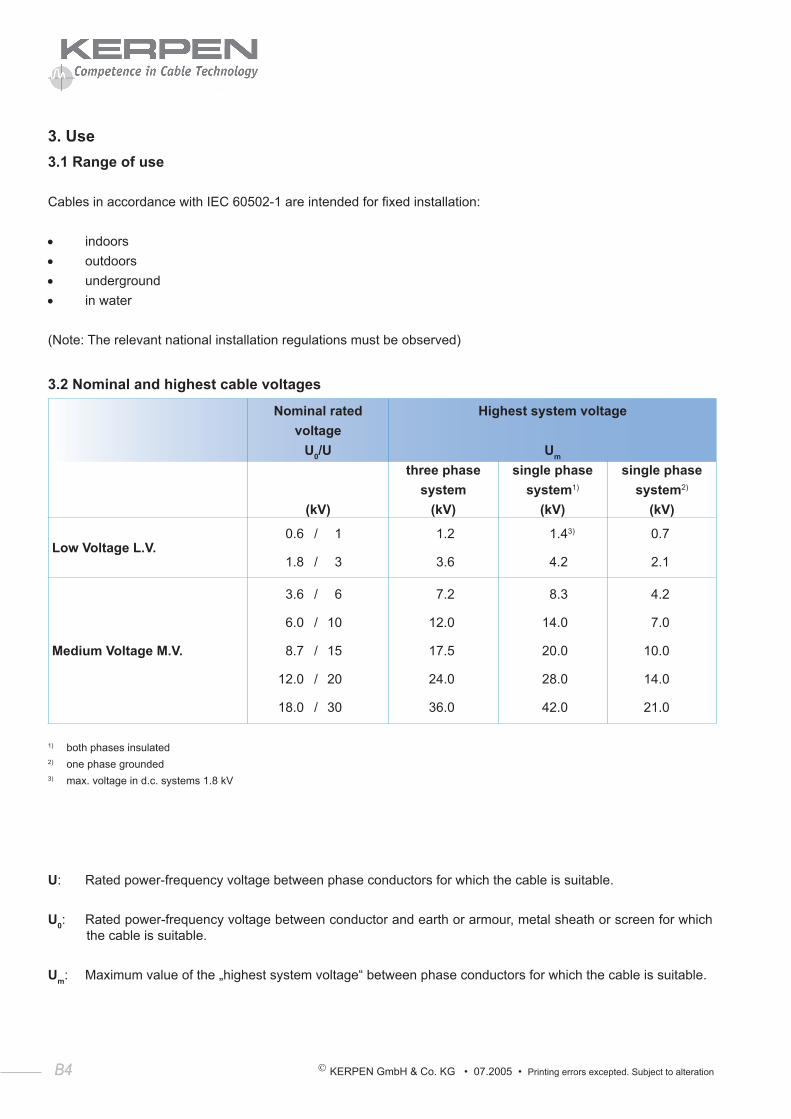
3.2 Nominal and highest cable voltages
Nominal ratedvoltage
U0/U
Highest system voltage
Um
(kV)
three phasesystem
(kV)
single phasesystem1)
(kV)
single phasesystem2)
(kV)
Low Voltage L.V. 0.6 / 1
1.8 / 3
1.2
3.6
1.43)
4.2
0.7
2.1
Medium Voltage M.V.
3.6 / 6
6.0 / 10
8.7 / 15
12.0 / 20
18.0 / 30
7.2
12.0
17.5
24.0
36.0
8.3
14.0
20.0
28.0
42.0
4.2
7.0
10.0
14.0
21.0
1) both phases insulated2) one phase grounded3) max. voltage in d.c. systems 1.8 kV
U: Rated power-frequency voltage between phase conductors for which the cable is suitable.
U0: Rated power-frequency voltage between conductor and earth or armour, metal sheath or screen for which the cable is suitable.
Um: Maximum value of the „highest system voltage“ between phase conductors for which the cable is suitable.
© KERPEN GmbH & Co. KG • 07.2005 • Printing errors excepted. Subject to alteration B5
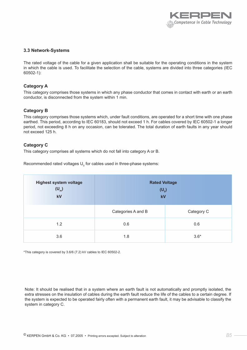
3.3 Network-Systems
The rated voltage of the cable for a given application shall be suitable for the operating conditions in the system in which the cable is used. To facilitate the selection of the cable, systems are divided into three categories (IEC 60502-1):
Category AThis category comprises those systems in which any phase conductor that comes in contact with earth or an earth conductor, is disconnected from the system within 1 min.
Category BThis category comprises those systems which, under fault conditions, are operated for a short time with one phase earthed. This period, according to IEC 60183, should not exceed 1 h. For cables covered by IEC 60502-1 a longer period, not exceeding 8 h on any occasion, can be tolerated. The total duration of earth faults in any year should not exceed 125 h.
Category CThis category comprises all systems which do not fall into category A or B.
Recommended rated voltages U0 for cables used in three-phase systems:
Highest system voltage(Um)
kV
Rated Voltage (U0)kV
Categories A and B Category C
1.2 0.6 0.6
3.6 1.8 3.6*
*This category is covered by 3.6/6 (7.2) kV cables to IEC 60502-2.
Note: It should be realised that in a system where an earth fault is not automatically and promptly isolated, the extra stresses on the insulation of cables during the earth fault reduce the life of the cables to a certain degree. If the system is expected to be operated fairly often with a permanent earth fault, it may be advisable to classify the system in category C.
B6 KERPEN GmbH & Co. KG • 07.2005 • Printing errors excepted. Subject to alteration
© KERPEN GmbH & Co. KG • 07.2005 • Printing errors excepted. Subject to alteration C1
Section 1:
PVC - Insulated
Low Voltage Cables (70 °C)
U0 /U 0.6 / 1 kV
C2 KERPEN GmbH & Co. KG • 07.2005 • Printing errors excepted. Subject to alteration
Power & Control Cable IEC 60502-1
(2-, 3-, 4- and 5-cores) U0/U 0.6 / 1 kVPVC-Insulation, PVC-SheathYY-flApplicationFor electricity supply and control in public networks and industrial plants; suitable for use in zone 1 and zone 2 group ΙΙ classified areas (IEC 60079-14).Recommended for direct burial. For indonicht or and outdoor installation in dry and wet locations, on racks, in conduits. (Local and / or legal requirements to be noted)
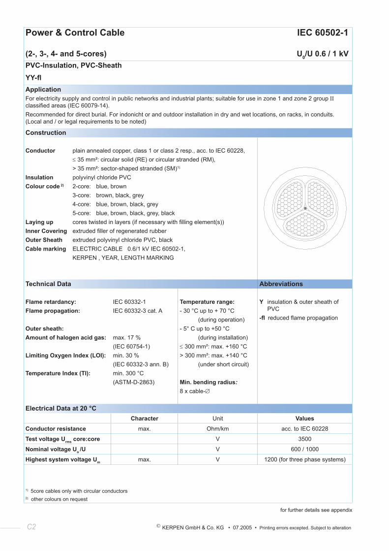
Construction
Conductor plain annealed copper, class 1 or class 2 resp., acc. to IEC 60228, ≤ 35 mm²: circular solid (RE) or circular stranded (RM), > 35 mm²: sector-shaped stranded (SM)1)
Insulation polyvinyl chloride PVCColour code 2) 2-core: blue, brown 3-core: brown, black, grey 4-core: blue, brown, black, grey 5-core: blue, brown, black, grey, black Laying up cores twisted in layers (if necessary with filling element(s))Inner Covering extruded filler of regenerated rubberOuter Sheath extruded polyvinyl chloride PVC, blackCable marking ELECTRIC CABLE 0.6/1 kV IEC 60502-1, KERPEN , YEAR, LENGTH MARKING
Technical Data Abbreviations
Flame retardancy: Flame propagation:
Outer sheath:Amount of halogen acid gas:
Limiting Oxygen Index (LOI):
Temperature Index (TI):
IEC 60332-1IEC 60332-3 cat. A
max. 17 % (IEC 60754-1)min. 30 %(IEC 60332-3 ann. B)min. 300 °C(ASTM-D-2863)
Temperature range:- 30 °C up to + 70 °C (during operation)- 5° C up to +50 °C (during installation)≤ 300 mm²: max. +160 °C> 300 mm²: max. +140 °C (under short circuit)
Min. bending radius:8 x cable-∅
Y insulation & outer sheath of PVC
-fl reduced flame propagation
Electrical Data at 20 °CCharacter Unit Values
Conductor resistance max. Ohm/km acc. to IEC 60228
Test voltage Urms core:core V 3500
Nominal voltage Uo /U V 600 / 1000
Highest system voltage Um max. V 1200 (for three phase systems)
1) 5core cables only with circular conductors 2) other colours on request
for further details see appendix
© KERPEN GmbH & Co. KG • 07.2005 • Printing errors excepted. Subject to alteration C3
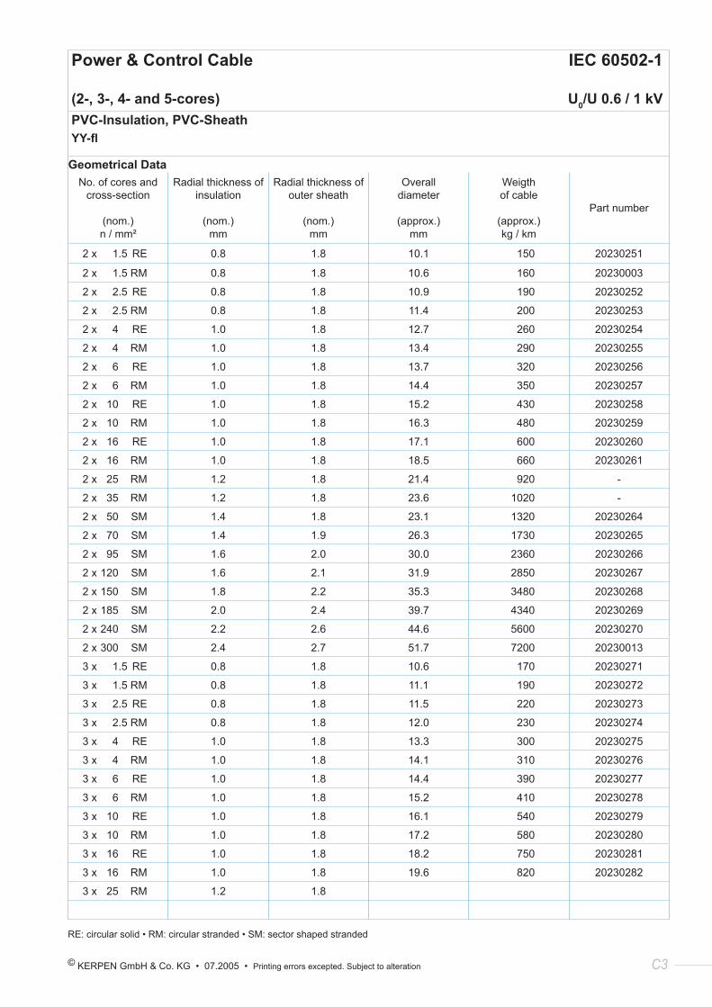
Geometrical DataNo. of cores and
cross-section
(nom.)n / mm²
Radial thickness of insulation
(nom.)mm
Radial thickness of outer sheath
(nom.)mm
Overall diameter
(approx.)mm
Weigth of cable
(approx.)kg / km
Part number
2 x 1.5 RE 0.8 1.8 10.1 150 20230251
2 x 1.5 RM 0.8 1.8 10.6 160 20230003
2 x 2.5 RE 0.8 1.8 10.9 190 20230252
2 x 2.5 RM 0.8 1.8 11.4 200 20230253
2 x 4 RE 1.0 1.8 12.7 260 20230254
2 x 4 RM 1.0 1.8 13.4 290 20230255
2 x 6 RE 1.0 1.8 13.7 320 20230256
2 x 6 RM 1.0 1.8 14.4 350 20230257
2 x 10 RE 1.0 1.8 15.2 430 20230258
2 x 10 RM 1.0 1.8 16.3 480 20230259
2 x 16 RE 1.0 1.8 17.1 600 20230260
2 x 16 RM 1.0 1.8 18.5 660 20230261
2 x 25 RM 1.2 1.8 21.4 920 -
2 x 35 RM 1.2 1.8 23.6 1020 -
2 x 50 SM 1.4 1.8 23.1 1320 20230264
2 x 70 SM 1.4 1.9 26.3 1730 20230265
2 x 95 SM 1.6 2.0 30.0 2360 20230266
2 x 120 SM 1.6 2.1 31.9 2850 20230267
2 x 150 SM 1.8 2.2 35.3 3480 20230268
2 x 185 SM 2.0 2.4 39.7 4340 20230269
2 x 240 SM 2.2 2.6 44.6 5600 20230270
2 x 300 SM 2.4 2.7 51.7 7200 20230013
3 x 1.5 RE 0.8 1.8 10.6 170 20230271
3 x 1.5 RM 0.8 1.8 11.1 190 20230272
3 x 2.5 RE 0.8 1.8 11.5 220 20230273
3 x 2.5 RM 0.8 1.8 12.0 230 20230274
3 x 4 RE 1.0 1.8 13.3 300 20230275
3 x 4 RM 1.0 1.8 14.1 310 20230276
3 x 6 RE 1.0 1.8 14.4 390 20230277
3 x 6 RM 1.0 1.8 15.2 410 20230278
3 x 10 RE 1.0 1.8 16.1 540 20230279
3 x 10 RM 1.0 1.8 17.2 580 20230280
3 x 16 RE 1.0 1.8 18.2 750 20230281
3 x 16 RM 1.0 1.8 19.6 820 20230282
3 x 25 RM 1.2 1.8
RE: circular solid • RM: circular stranded • SM: sector shaped stranded
Power & Control Cable IEC 60502-1
(2-, 3-, 4- and 5-cores) U0/U 0.6 / 1 kVPVC-Insulation, PVC-SheathYY-fl
C4 KERPEN GmbH & Co. KG • 07.2005 • Printing errors excepted. Subject to alteration
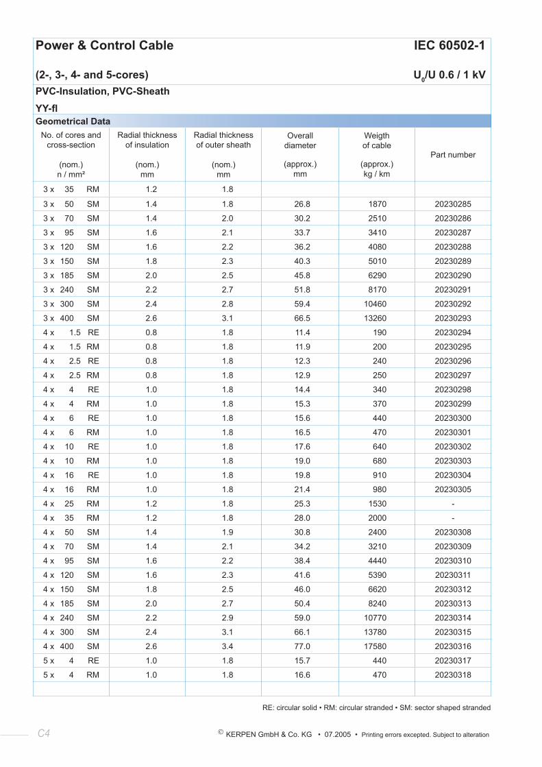
Power & Control Cable IEC 60502-1
(2-, 3-, 4- and 5-cores) U0/U 0.6 / 1 kVPVC-Insulation, PVC-SheathYY-flGeometrical Data
No. of cores and cross-section
(nom.)n / mm²
Radial thickness of insulation
(nom.)mm
Radial thickness of outer sheath
(nom.)mm
Overall diameter
(approx.)mm
Weigth of cable
(approx.)kg / km
Part number
3 x 35 RM 1.2 1.8
3 x 50 SM 1.4 1.8 26.8 1870 20230285
3 x 70 SM 1.4 2.0 30.2 2510 20230286
3 x 95 SM 1.6 2.1 33.7 3410 20230287
3 x 120 SM 1.6 2.2 36.2 4080 20230288
3 x 150 SM 1.8 2.3 40.3 5010 20230289
3 x 185 SM 2.0 2.5 45.8 6290 20230290
3 x 240 SM 2.2 2.7 51.8 8170 20230291
3 x 300 SM 2.4 2.8 59.4 10460 20230292
3 x 400 SM 2.6 3.1 66.5 13260 20230293
4 x 1.5 RE 0.8 1.8 11.4 190 20230294
4 x 1.5 RM 0.8 1.8 11.9 200 20230295
4 x 2.5 RE 0.8 1.8 12.3 240 20230296
4 x 2.5 RM 0.8 1.8 12.9 250 20230297
4 x 4 RE 1.0 1.8 14.4 340 20230298
4 x 4 RM 1.0 1.8 15.3 370 20230299
4 x 6 RE 1.0 1.8 15.6 440 20230300
4 x 6 RM 1.0 1.8 16.5 470 20230301
4 x 10 RE 1.0 1.8 17.6 640 20230302
4 x 10 RM 1.0 1.8 19.0 680 20230303
4 x 16 RE 1.0 1.8 19.8 910 20230304
4 x 16 RM 1.0 1.8 21.4 980 20230305
4 x 25 RM 1.2 1.8 25.3 1530 -
4 x 35 RM 1.2 1.8 28.0 2000 -
4 x 50 SM 1.4 1.9 30.8 2400 20230308
4 x 70 SM 1.4 2.1 34.2 3210 20230309
4 x 95 SM 1.6 2.2 38.4 4440 20230310
4 x 120 SM 1.6 2.3 41.6 5390 20230311
4 x 150 SM 1.8 2.5 46.0 6620 20230312
4 x 185 SM 2.0 2.7 50.4 8240 20230313
4 x 240 SM 2.2 2.9 59.0 10770 20230314
4 x 300 SM 2.4 3.1 66.1 13780 20230315
4 x 400 SM 2.6 3.4 77.0 17580 20230316
5 x 4 RE 1.0 1.8 15.7 440 20230317
5 x 4 RM 1.0 1.8 16.6 470 20230318
RE: circular solid • RM: circular stranded • SM: sector shaped stranded
© KERPEN GmbH & Co. KG • 07.2005 • Printing errors excepted. Subject to alteration C5
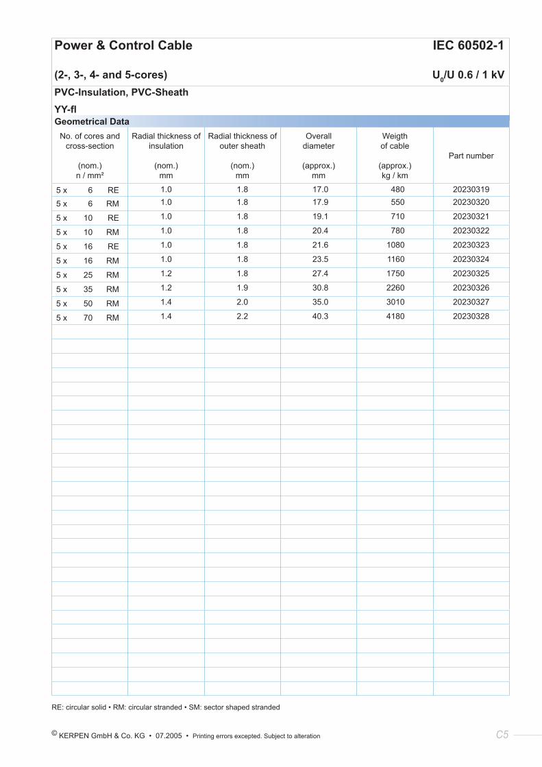
Power & Control Cable IEC 60502-1
(2-, 3-, 4- and 5-cores) U0/U 0.6 / 1 kVPVC-Insulation, PVC-SheathYY-flGeometrical Data
No. of cores and cross-section
(nom.)n / mm²
Radial thickness of insulation
(nom.)mm
Radial thickness of outer sheath
(nom.)mm
Overall diameter
(approx.)mm
Weigth of cable
(approx.)kg / km
Part number
5 x 6 RE 1.0 1.8 17.0 480 20230319
5 x 6 RM 1.0 1.8 17.9 550 20230320
5 x 10 RE 1.0 1.8 19.1 710 20230321
5 x 10 RM 1.0 1.8 20.4 780 20230322
5 x 16 RE 1.0 1.8 21.6 1080 20230323
5 x 16 RM 1.0 1.8 23.5 1160 20230324
5 x 25 RM 1.2 1.8 27.4 1750 20230325
5 x 35 RM 1.2 1.9 30.8 2260 20230326
5 x 50 RM 1.4 2.0 35.0 3010 20230327
5 x 70 RM 1.4 2.2 40.3 4180 20230328
RE: circular solid • RM: circular stranded • SM: sector shaped stranded
C6 KERPEN GmbH & Co. KG • 07.2005 • Printing errors excepted. Subject to alteration
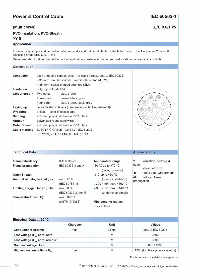
Power & Control Cable IEC 60502-1
(Multicores) U0/U 0.6/1 kVPVC-Insulation, PVC-SheathYY-flApplication
For electricity supply and control in public networks and industrial plants; suitable for use in zone 1 and zone 2 group ΙΙ classified areas (IEC 60079-14).Recommended for direct burial. For indoor and outdoor installation in dry and wet locations, on racks, in conduits
Construction
Conductor plain annealed copper, class 1 or class 2 resp., acc. to IEC 60228, ≤ 35 mm²: circular solid (RE) or circular stranded (RM), > 35 mm²: sector-shaped stranded (SM)Insulation polyvinyl chloride PVCColour code 1) Two-core: blue, brown Three-core: brown, black, grey Four-core: blue, brown, black, greyLaying up cores twisted in layers (if necessary with filling element(s))Wrapping at least 1 layer of plastic tapeBedding extruded polyvinyl chloride PVC, blackArmour galvanized round steel wiresOuter Sheath extruded polyvinyl chloride PVC, blackCable marking ELECTRIC CABLE 0.6/1 kV IEC 60502-1 KERPEN, YEAR, LENGTH, MARKING
Technical Data Abbreviations
Flame retardancy:Flame propagation:
Outer Sheath:Amount of halogen acid gas:
Limiting Oxygen Index (LOI):
Temperatur Index (TI):
IEC 60332-1IEC 60332-3 cat. A
max. 17 %(IEC 60754-1)min. 30 %(IEC 60332-3 ann. B)min. 300 °C(ASTM-D-2863)
Temperature range:-30 °C up to +70 °C (during operation)
-5°C up to +50 °C (during installation)≤ 300 mm²: max. +160 °C> 300 mm²: max. +140 °C (under short circuit)
Min. bending radius: 8 x cable-∅
Y insulation, bedding & outer sheath of PVC R round steel wire armour-fl reduced flame propagation
Electrical Data at 20 °CCharacter Unit Values
Conductor resistance max. Ω/km acc. to IEC 60228
Test voltage Urms core: core V 3500
Test voltage Urms core: armour V 3500
Nominal voltage Uo /U V 600 / 1000
Highest system voltage Um max. V 1200 (for three phase systems)
For further electrical details see appendix
© KERPEN GmbH & Co. KG • 07.2005 • Printing errors excepted. Subject to alteration C7
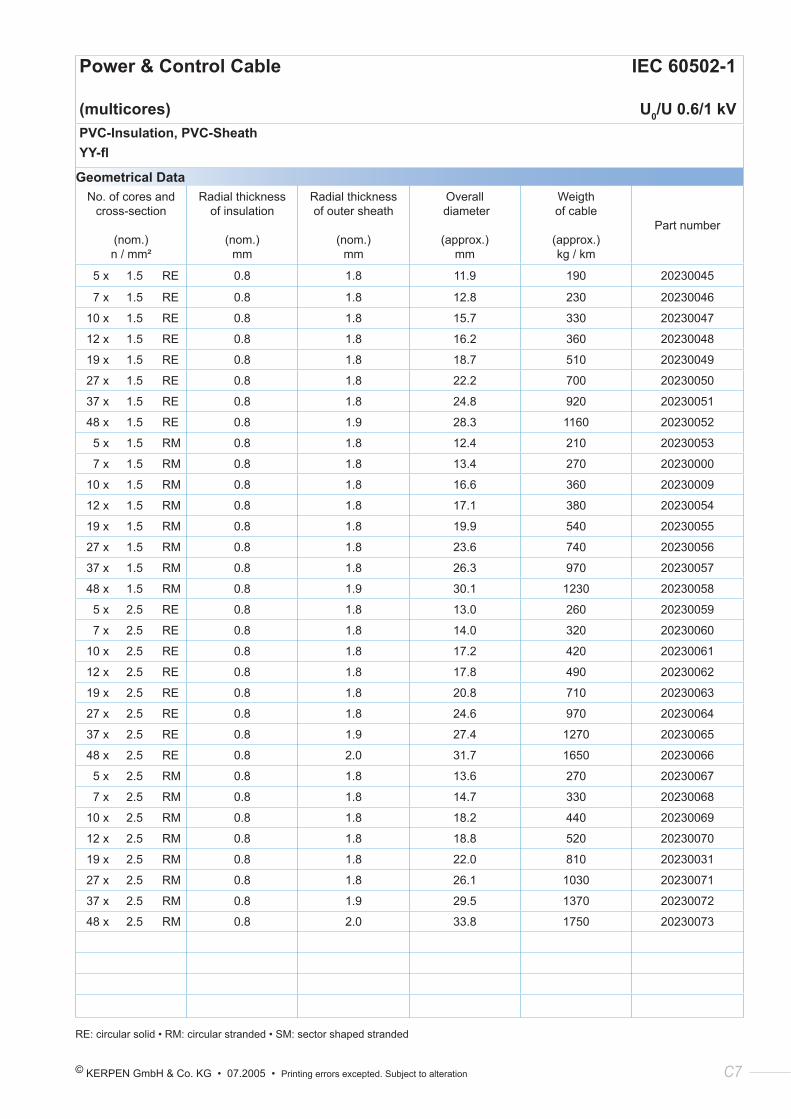
Power & Control Cable IEC 60502-1
(multicores) U0/U 0.6/1 kVPVC-Insulation, PVC-SheathYY-fl
Geometrical DataNo. of cores and
cross-section
(nom.) n / mm²
Radial thickness of insulation
(nom.) mm
Radial thickness of outer sheath
(nom.) mm
Overall diameter
(approx.) mm
Weigth of cable
(approx.) kg / km
Part number
5 x 1.5 RE 0.8 1.8 11.9 190 20230045
7 x 1.5 RE 0.8 1.8 12.8 230 20230046
10 x 1.5 RE 0.8 1.8 15.7 330 20230047
12 x 1.5 RE 0.8 1.8 16.2 360 20230048
19 x 1.5 RE 0.8 1.8 18.7 510 20230049
27 x 1.5 RE 0.8 1.8 22.2 700 20230050
37 x 1.5 RE 0.8 1.8 24.8 920 20230051
48 x 1.5 RE 0.8 1.9 28.3 1160 20230052
5 x 1.5 RM 0.8 1.8 12.4 210 20230053
7 x 1.5 RM 0.8 1.8 13.4 270 20230000
10 x 1.5 RM 0.8 1.8 16.6 360 20230009
12 x 1.5 RM 0.8 1.8 17.1 380 20230054
19 x 1.5 RM 0.8 1.8 19.9 540 20230055
27 x 1.5 RM 0.8 1.8 23.6 740 20230056
37 x 1.5 RM 0.8 1.8 26.3 970 20230057
48 x 1.5 RM 0.8 1.9 30.1 1230 20230058
5 x 2.5 RE 0.8 1.8 13.0 260 20230059
7 x 2.5 RE 0.8 1.8 14.0 320 20230060
10 x 2.5 RE 0.8 1.8 17.2 420 20230061
12 x 2.5 RE 0.8 1.8 17.8 490 20230062
19 x 2.5 RE 0.8 1.8 20.8 710 20230063
27 x 2.5 RE 0.8 1.8 24.6 970 20230064
37 x 2.5 RE 0.8 1.9 27.4 1270 20230065
48 x 2.5 RE 0.8 2.0 31.7 1650 20230066
5 x 2.5 RM 0.8 1.8 13.6 270 20230067
7 x 2.5 RM 0.8 1.8 14.7 330 20230068
10 x 2.5 RM 0.8 1.8 18.2 440 20230069
12 x 2.5 RM 0.8 1.8 18.8 520 20230070
19 x 2.5 RM 0.8 1.8 22.0 810 20230031
27 x 2.5 RM 0.8 1.8 26.1 1030 20230071
37 x 2.5 RM 0.8 1.9 29.5 1370 20230072
48 x 2.5 RM 0.8 2.0 33.8 1750 20230073
RE: circular solid • RM: circular stranded • SM: sector shaped stranded
C8 KERPEN GmbH & Co. KG • 07.2005 • Printing errors excepted. Subject to alteration
Power & Control Cable IEC 60502-1
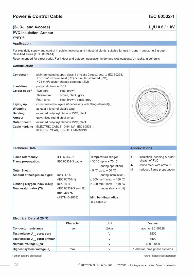
(2-, 3-, and 4-cores) U0/U 0.6 / 1 kVPVC-Insulation, ArmourYYRY-flApplication
For electricity supply and control in public networks and industrial plants; suitable for use in zone 1 and zone 2 group ΙΙ classified areas (IEC 60079-14).Recommended for direct burial. For indoor and outdoor installation in dry and wet locations, on racks, in conduits
Construction
Conductor plain annealed copper, class 1 or class 2 resp., acc. to IEC 60228, ≤ 35 mm²: circular solid (RE) or circular stranded (RM), > 35 mm²: sector-shaped stranded (SM)Insulation polyvinyl chloride PVCColour code 1) Two-core: blue, brown Three-core: brown, black, grey Four-core: blue, brown, black, greyLaying up cores twisted in layers (if necessary with filling element(s))Wrapping at least 1 layer of plastic tapeBedding extruded polyvinyl chloride PVC, blackArmour galvanized round steel wiresOuter Sheath extruded polyvinyl chloride PVC, blackCable marking ELECTRIC CABLE 0.6/1 kV IEC 60502-1 KERPEN, YEAR, LENGTH, MARKING
Technical Data Abbreviations
Flame retardancy:Flame propagation:
Outer Sheath:Amount of halogen acid gas:
Limiting Oxygen Index (LOI):Temperatur Index (TI):
IEC 60332-1IEC 60332-3 cat. A
max. 17 %(IEC 60754-1)min. 30 %(IEC 60332-3 ann. B)min. 300 °C(ASTM-D-2863)
Temperature range:- 30 °C up to + 70 °C (during operation)- 5 °C up to + 50 °C (during installation)≤ 300 mm²: max. + 160 °C> 300 mm²: max. + 140 °C (under short circuit)
Min. bending radius: 8 x cable-∅
Y insulation, bedding & outer sheath of PVC R round steel wire armour-fl reduced flame propagation
Electrical Data at 20 °CCharacter Unit Values
Conductor resistance max. Ω/km acc. to IEC 60228
Test voltage Urms core: core V 3500
Test voltage Urms core: armour V 3500
Nominal voltage Uo /U V 600 / 1000
Highest system voltage Um max. V 1200 (for three phase systems
1) other colours on request further details see appendix
© KERPEN GmbH & Co. KG • 07.2005 • Printing errors excepted. Subject to alteration C9
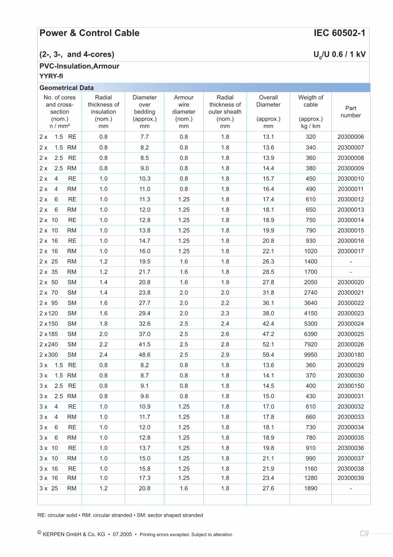
Power & Control Cable IEC 60502-1
(2-, 3-, and 4-cores) U0/U 0.6 / 1 kVPVC-Insulation,ArmourYYRY-fl
Geometrical DataNo. of cores and cross-
section(nom.) n / mm²
Radial thickness of insulation
(nom.) mm
Diameter over
bedding(approx.)
mm
Armour wire
diameter(nom.)
mm
Radial thickness of outer sheath
(nom.) mm
Overall Diameter
(approx.) mm
Weigth of cable
(approx.) kg / km
Part number
2 x 1.5 RE 0.8 7.7 0.8 1.8 13.1 320 20300006
2 x 1.5 RM 0.8 8.2 0.8 1.8 13.6 340 20300007
2 x 2.5 RE 0.8 8.5 0.8 1.8 13.9 360 20300008
2 x 2.5 RM 0.8 9.0 0.8 1.8 14.4 380 20300009
2 x 4 RE 1.0 10.3 0.8 1.8 15.7 450 20300010
2 x 4 RM 1.0 11.0 0.8 1.8 16.4 490 20300011
2 x 6 RE 1.0 11.3 1.25 1.8 17.4 610 20300012
2 x 6 RM 1.0 12.0 1.25 1.8 18.1 650 20300013
2 x 10 RE 1.0 12.8 1.25 1.8 18.9 750 20300014
2 x 10 RM 1.0 13.8 1.25 1.8 19.9 790 20300015
2 x 16 RE 1.0 14.7 1.25 1.8 20.8 930 20300016
2 x 16 RM 1.0 16.0 1.25 1.8 22.1 1020 20300017
2 x 25 RM 1.2 19.5 1.6 1.8 26.3 1400 -
2 x 35 RM 1.2 21.7 1.6 1.8 28.5 1700 -
2 x 50 SM 1.4 20.8 1.6 1.9 27.8 2050 20300020
2 x 70 SM 1.4 23.8 2.0 2.0 31.8 2740 20300021
2 x 95 SM 1.6 27.7 2.0 2.2 36.1 3640 20300022
2 x 120 SM 1.6 29.4 2.0 2.3 38.0 4150 20300023
2 x 150 SM 1.8 32.6 2.5 2.4 42.4 5300 20300024
2 x 185 SM 2.0 37.0 2.5 2.6 47.2 6390 20300025
2 x 240 SM 2.2 41.5 2.5 2.8 52.1 7920 20300026
2 x 300 SM 2.4 48.6 2.5 2.9 59.4 9950 20300180
3 x 1.5 RE 0.8 8.2 0.8 1.8 13.6 360 20300029
3 x 1.5 RM 0.8 8.7 0.8 1.8 14.1 370 20300030
3 x 2.5 RE 0.8 9.1 0.8 1.8 14.5 400 20300150
3 x 2.5 RM 0.8 9.6 0.8 1.8 15.0 430 20300031
3 x 4 RE 1.0 10.9 1.25 1.8 17.0 610 20300032
3 x 4 RM 1.0 11.7 1.25 1.8 17.8 660 20300033
3 x 6 RE 1.0 12.0 1.25 1.8 18.1 730 20300034
3 x 6 RM 1.0 12.8 1.25 1.8 18.9 780 20300035
3 x 10 RE 1.0 13.7 1.25 1.8 19.8 910 20300036
3 x 10 RM 1.0 15.0 1.25 1.8 21.1 990 20300037
3 x 16 RE 1.0 15.8 1.25 1.8 21.9 1160 203000383 x 16 RM 1.0 17.3 1.25 1.8 23.4 1280 20300039
3 x 25 RM 1.2 20.8 1.6 1.8 27.6 1890 -
RE: circular solid • RM: circular stranded • SM: sector shaped stranded
C10 KERPEN GmbH & Co. KG • 07.2005 • Printing errors excepted. Subject to alteration
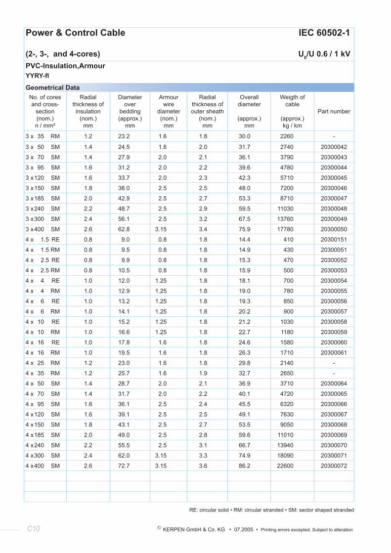
Power & Control Cable IEC 60502-1
(2-, 3-, and 4-cores) U0/U 0.6 / 1 kVPVC-Insulation,ArmourYYRY-fl
Geometrical DataNo. of cores and cross-
section(nom.) n / mm²
Radial thickness of insulation
(nom.) mm
Diameter over
bedding(approx.)
mm
Armour wire
diameter(nom.)
mm
Radial thickness of outer sheath
(nom.) mm
Overall diameter
(approx.) mm
Weigth of cable
(approx.) kg / km
Part number
3 x 35 RM 1.2 23.2 1.6 1.8 30.0 2260 -
3 x 50 SM 1.4 24.5 1.6 2.0 31.7 2740 20300042
3 x 70 SM 1.4 27.9 2.0 2.1 36.1 3790 20300043
3 x 95 SM 1.6 31.2 2.0 2.2 39.6 4780 20300044
3 x 120 SM 1.6 33.7 2.0 2.3 42.3 5710 20300045
3 x 150 SM 1.8 38.0 2.5 2.5 48.0 7200 20300046
3 x 185 SM 2.0 42.9 2.5 2.7 53.3 8710 20300047
3 x 240 SM 2.2 48.7 2.5 2.9 59.5 11030 20300048
3 x 300 SM 2.4 56.1 2.5 3.2 67.5 13760 20300049
3 x 400 SM 2.6 62.8 3.15 3.4 75.9 17780 20300050
4 x 1.5 RE 0.8 9.0 0.8 1.8 14.4 410 20300151
4 x 1.5 RM 0.8 9.5 0.8 1.8 14.9 430 20300051
4 x 2.5 RE 0.8 9.9 0.8 1.8 15.3 470 20300052
4 x 2.5 RM 0.8 10.5 0.8 1.8 15.9 500 20300053
4 x 4 RE 1.0 12.0 1.25 1.8 18.1 700 20300054
4 x 4 RM 1.0 12.9 1.25 1.8 19.0 780 20300055
4 x 6 RE 1.0 13.2 1.25 1.8 19.3 850 20300056
4 x 6 RM 1.0 14.1 1.25 1.8 20.2 900 20300057
4 x 10 RE 1.0 15.2 1.25 1.8 21.2 1030 20300058
4 x 10 RM 1.0 16.6 1.25 1.8 22.7 1180 20300059
4 x 16 RE 1.0 17.8 1.6 1.8 24.6 1580 20300060
4 x 16 RM 1.0 19.5 1.6 1.8 26.3 1710 20300061
4 x 25 RM 1.2 23.0 1.6 1.8 29.8 2140 -
4 x 35 RM 1.2 25.7 1.6 1.9 32.7 2650 -
4 x 50 SM 1.4 28.7 2.0 2.1 36.9 3710 20300064
4 x 70 SM 1.4 31.7 2.0 2.2 40.1 4720 20300065
4 x 95 SM 1.6 36.1 2.5 2.4 45.5 6320 20300066
4 x 120 SM 1.6 39.1 2.5 2.5 49.1 7630 20300067
4 x 150 SM 1.8 43.1 2.5 2.7 53.5 9050 20300068
4 x 185 SM 2.0 49.0 2.5 2.8 59.6 11010 20300069
4 x 240 SM 2.2 55.5 2.5 3.1 66.7 13940 20300070
4 x 300 SM 2.4 62.0 3.15 3.3 74.9 18090 20300071
4 x 400 SM 2.6 72.7 3.15 3.6 86.2 22600 20300072
RE: circular solid • RM: circular stranded • SM: sector shaped stranded
© KERPEN GmbH & Co. KG • 07.2005 • Printing errors excepted. Subject to alteration C11
KERPEN’s Focus:
Competence - Flexibility - Quality - Service
Competence
• cable engineering to over 150 national, international and customer standards
• specification service based on electrical, mechanical, environmental and other customer/site requirements
• more than 30.000 designs
• key supplier to oil, gas, petrochemical and chemical industry
• consulting service for design
C12 KERPEN GmbH & Co. KG • 07.2005 • Printing errors excepted. Subject to alteration
Power & Control Cable IEC 60502-1
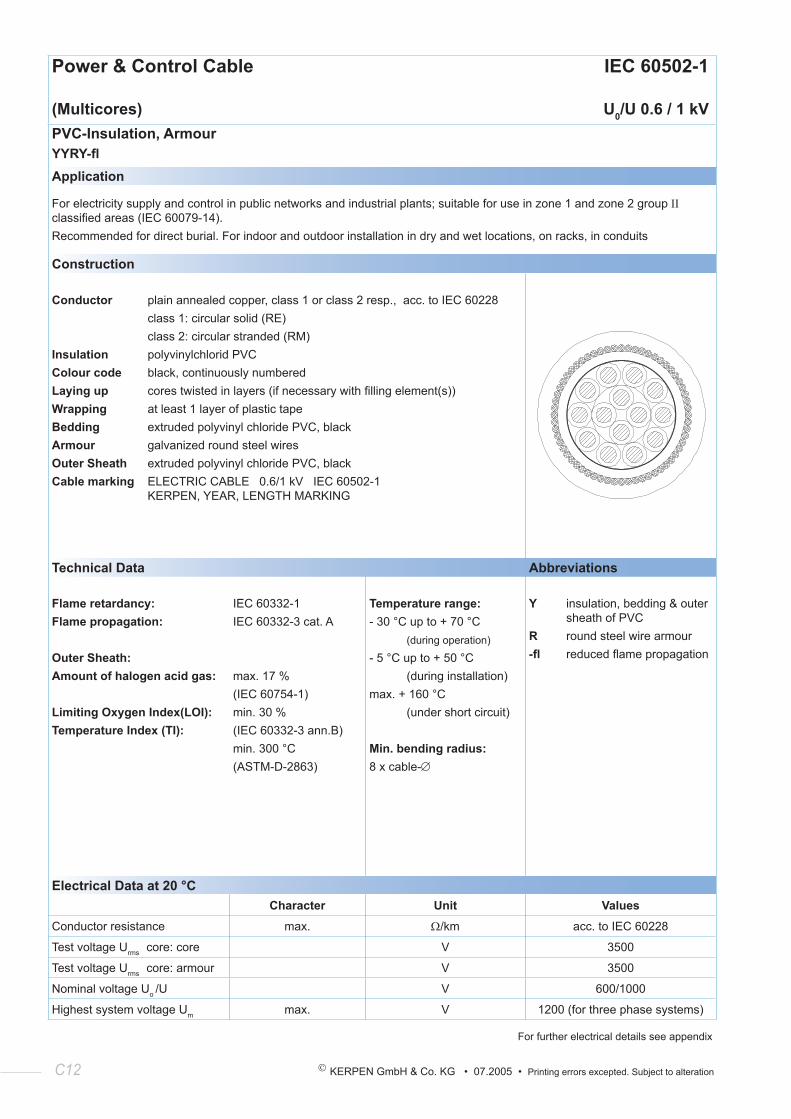
(Multicores) U0/U 0.6 / 1 kVPVC-Insulation, ArmourYYRY-flApplication
For electricity supply and control in public networks and industrial plants; suitable for use in zone 1 and zone 2 group ΙΙ classified areas (IEC 60079-14).Recommended for direct burial. For indoor and outdoor installation in dry and wet locations, on racks, in conduits
Construction
Conductor plain annealed copper, class 1 or class 2 resp., acc. to IEC 60228 class 1: circular solid (RE) class 2: circular stranded (RM)Insulation polyvinylchlorid PVCColour code black, continuously numberedLaying up cores twisted in layers (if necessary with filling element(s))Wrapping at least 1 layer of plastic tapeBedding extruded polyvinyl chloride PVC, blackArmour galvanized round steel wiresOuter Sheath extruded polyvinyl chloride PVC, blackCable marking ELECTRIC CABLE 0.6/1 kV IEC 60502-1 KERPEN, YEAR, LENGTH MARKING
Technical Data Abbreviations
Flame retardancy:Flame propagation:
Outer Sheath:Amount of halogen acid gas:
Limiting Oxygen Index(LOI):Temperature Index (TI):
IEC 60332-1IEC 60332-3 cat. A
max. 17 %(IEC 60754-1)min. 30 %(IEC 60332-3 ann.B)min. 300 °C(ASTM-D-2863)
Temperature range:- 30 °C up to + 70 °C (during operation)
- 5 °C up to + 50 °C (during installation)max. + 160 °C (under short circuit)
Min. bending radius:8 x cable-∅
Y insulation, bedding & outer sheath of PVCR round steel wire armour-fl reduced flame propagation
Electrical Data at 20 °CCharacter Unit Values
Conductor resistance max. Ω/km acc. to IEC 60228
Test voltage Urms core: core V 3500
Test voltage Urms core: armour V 3500
Nominal voltage Uo /U V 600/1000
Highest system voltage Um max. V 1200 (for three phase systems)
For further electrical details see appendix
© KERPEN GmbH & Co. KG • 07.2005 • Printing errors excepted. Subject to alteration C13
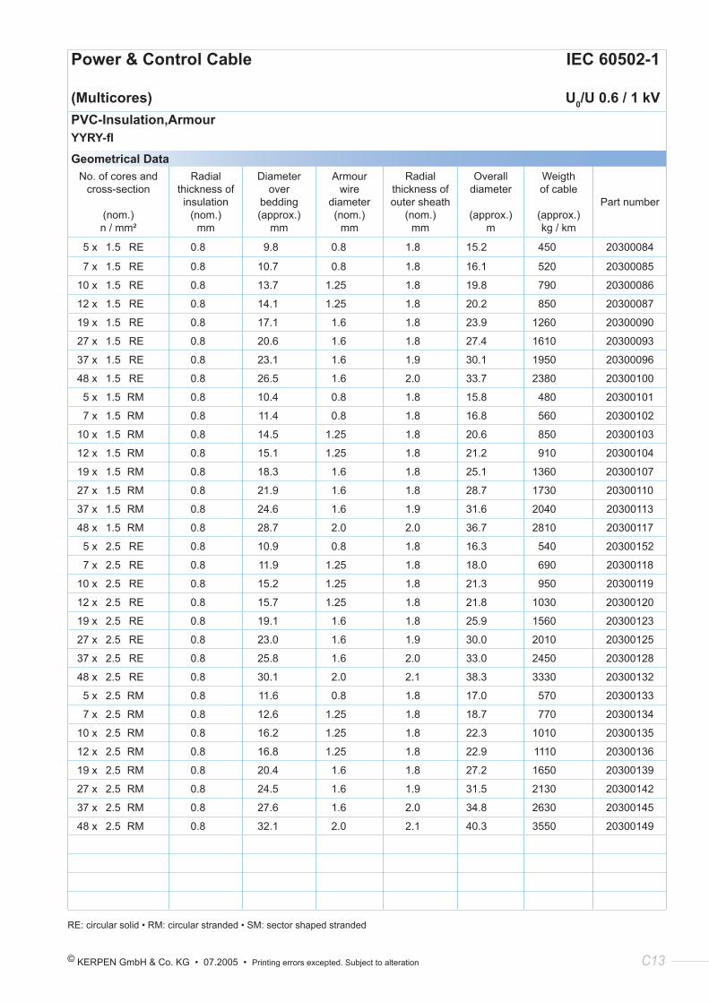
Power & Control Cable IEC 60502-1
(Multicores) U0/U 0.6 / 1 kVPVC-Insulation,ArmourYYRY-fl
Geometrical DataNo. of cores and
cross-section
(nom.) n / mm²
Radial thickness of insulation
(nom.) mm
Diameter over
bedding(approx.)
mm
Armour wire
diameter(nom.)
mm
Radial thickness of outer sheath
(nom.) mm
Overall diameter
(approx.) m
Weigth of cable
(approx.) kg / km
Part number
5 x 1.5 RE 0.8 9.8 0.8 1.8 15.2 450 20300084
7 x 1.5 RE 0.8 10.7 0.8 1.8 16.1 520 20300085
10 x 1.5 RE 0.8 13.7 1.25 1.8 19.8 790 20300086
12 x 1.5 RE 0.8 14.1 1.25 1.8 20.2 850 20300087
19 x 1.5 RE 0.8 17.1 1.6 1.8 23.9 1260 20300090
27 x 1.5 RE 0.8 20.6 1.6 1.8 27.4 1610 20300093
37 x 1.5 RE 0.8 23.1 1.6 1.9 30.1 1950 20300096
48 x 1.5 RE 0.8 26.5 1.6 2.0 33.7 2380 20300100
5 x 1.5 RM 0.8 10.4 0.8 1.8 15.8 480 20300101
7 x 1.5 RM 0.8 11.4 0.8 1.8 16.8 560 20300102
10 x 1.5 RM 0.8 14.5 1.25 1.8 20.6 850 20300103
12 x 1.5 RM 0.8 15.1 1.25 1.8 21.2 910 20300104
19 x 1.5 RM 0.8 18.3 1.6 1.8 25.1 1360 20300107
27 x 1.5 RM 0.8 21.9 1.6 1.8 28.7 1730 20300110
37 x 1.5 RM 0.8 24.6 1.6 1.9 31.6 2040 20300113
48 x 1.5 RM 0.8 28.7 2.0 2.0 36.7 2810 20300117
5 x 2.5 RE 0.8 10.9 0.8 1.8 16.3 540 20300152
7 x 2.5 RE 0.8 11.9 1.25 1.8 18.0 690 20300118
10 x 2.5 RE 0.8 15.2 1.25 1.8 21.3 950 20300119
12 x 2.5 RE 0.8 15.7 1.25 1.8 21.8 1030 20300120
19 x 2.5 RE 0.8 19.1 1.6 1.8 25.9 1560 20300123
27 x 2.5 RE 0.8 23.0 1.6 1.9 30.0 2010 20300125
37 x 2.5 RE 0.8 25.8 1.6 2.0 33.0 2450 20300128
48 x 2.5 RE 0.8 30.1 2.0 2.1 38.3 3330 20300132
5 x 2.5 RM 0.8 11.6 0.8 1.8 17.0 570 20300133
7 x 2.5 RM 0.8 12.6 1.25 1.8 18.7 770 20300134
10 x 2.5 RM 0.8 16.2 1.25 1.8 22.3 1010 20300135
12 x 2.5 RM 0.8 16.8 1.25 1.8 22.9 1110 20300136
19 x 2.5 RM 0.8 20.4 1.6 1.8 27.2 1650 20300139
27 x 2.5 RM 0.8 24.5 1.6 1.9 31.5 2130 20300142
37 x 2.5 RM 0.8 27.6 1.6 2.0 34.8 2630 20300145
48 x 2.5 RM 0.8 32.1 2.0 2.1 40.3 3550 20300149
RE: circular solid • RM: circular stranded • SM: sector shaped stranded

C14 KERPEN GmbH & Co. KG • 07.2005 • Printing errors excepted. Subject to alteration
© KERPEN GmbH & Co. KG • 07.2005 • Printing errors excepted. Subject to alteration D1
Section 2:
XLPE - Insulated
Low Voltage Cables (90 °C)
U0 /U 0.6 / 1 kV
D2 KERPEN GmbH & Co. KG • 07.2005 • Printing errors excepted. Subject to alteration
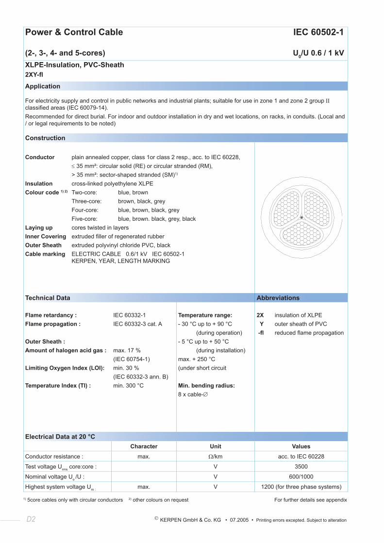
Power & Control Cable IEC 60502-1
(2-, 3-, 4- and 5-cores) U0/U 0.6 / 1 kVXLPE-Insulation, PVC-Sheath2XY-fl
Application
For electricity supply and control in public networks and industrial plants; suitable for use in zone 1 and zone 2 group ΙΙ classified areas (IEC 60079-14).Recommended for direct burial. For indoor and outdoor installation in dry and wet locations, on racks, in conduits. (Local and / or legal requirements to be noted)
Construction
Conductor plain annealed copper, class 1or class 2 resp., acc. to IEC 60228, ≤ 35 mm²: circular solid (RE) or circular stranded (RM), > 35 mm²: sector-shaped stranded (SM)1)
Insulation cross-linked polyethylene XLPEColour code 1) 2) Two-core: blue, brown Three-core: brown, black, grey Four-core: blue, brown, black, grey Five-core: blue, brown. black, grey, blackLaying up cores twisted in layersInner Covering extruded filler of regenerated rubberOuter Sheath extruded polyvinyl chloride PVC, blackCable marking ELECTRIC CABLE 0.6/1 kV IEC 60502-1 KERPEN, YEAR, LENGTH MARKING
Technical Data Abbreviations
Flame retardancy :Flame propagation :
Outer Sheath :Amount of halogen acid gas :
Limiting Oxygen Index (LOI):
Temperature Index (TI) :
IEC 60332-1IEC 60332-3 cat. A
max. 17 %(IEC 60754-1)min. 30 %(IEC 60332-3 ann. B)min. 300 °C
Temperature range:- 30 °C up to + 90 °C (during operation)- 5 °C up to + 50 °C (during installation)max. + 250 °C(under short circuit
Min. bending radius:8 x cable-∅
2X insulation of XLPE Y outer sheath of PVC -fl reduced flame propagation
Electrical Data at 20 °CCharacter Unit Values
Conductor resistance : max. Ω/km acc. to IEC 60228
Test voltage Urms core:core : V 3500
Nominal voltage Uo /U : V 600/1000
Highest system voltage Um : max. V 1200 (for three phase systems)
1) 5core cables only with circular conductors 2) other colours on request For further details see appendix
© KERPEN GmbH & Co. KG • 07.2005 • Printing errors excepted. Subject to alteration D3
Power & Control Cable IEC 60502-1
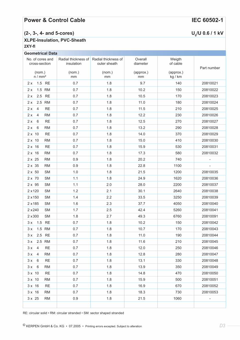
(2-, 3-, 4- and 5-cores) U0/U 0.6 / 1 kVXLPE-Insulation, PVC-Sheath2XY-fl
Geometrical DataNo. of cores and
cross-section
(nom.) n / mm²
Radial thickness of insulation
(nom.) mm
Radial thickness of outer sheath
(nom.) mm
Overall diameter
(approx.) mm
Weigth of cable
(approx.) kg / km
Part number
2 x 1.5 RE 0.7 1.8 9.7 140 20810021
2 x 1.5 RM 0.7 1.8 10.2 150 20810022
2 x 2.5 RE 0.7 1.8 10.5 170 20810023
2 x 2.5 RM 0.7 1.8 11.0 180 20810024
2 x 4 RE 0.7 1.8 11.5 210 20810025
2 x 4 RM 0.7 1.8 12.2 230 20810026
2 x 6 RE 0.7 1.8 12.5 270 20810027
2 x 6 RM 0.7 1.8 13.2 290 20810028
2 x 10 RE 0.7 1.8 14.0 370 20810029
2 x 10 RM 0.7 1.8 15.0 410 20810030
2 x 16 RE 0.7 1.8 15.9 530 20810031
2 x 16 RM 0.7 1.8 17.3 580 20810032
2 x 25 RM 0.9 1.8 20.2 740 -
2 x 35 RM 0.9 1.8 22.8 1100 -
2 x 50 SM 1.0 1.8 21.5 1200 20810035
2 x 70 SM 1.1 1.8 24.9 1620 20810036
2 x 95 SM 1.1 2.0 28.0 2200 20810037
2 x 120 SM 1.2 2.1 30.1 2640 20810038
2 x 150 SM 1.4 2.2 33.5 3250 20810039
2 x 185 SM 1.6 2.3 37.7 4050 20810040
2 x 240 SM 1.7 2.5 42.4 5260 20810041
2 x 300 SM 1.8 2.7 49.3 6760 20810091
3 x 1.5 RE 0.7 1.8 10.2 150 20810042
3 x 1.5 RM 0.7 1.8 10.7 170 20810043
3 x 2.5 RE 0.7 1.8 11.0 190 20810044
3 x 2.5 RM 0.7 1.8 11.6 210 20810045
3 x 4 RE 0.7 1.8 12.0 250 20810046
3 x 4 RM 0.7 1.8 12.8 280 20810047
3 x 6 RE 0.7 1.8 13.1 330 20810048
3 x 6 RM 0.7 1.8 13.9 350 20810049
3 x 10 RE 0.7 1.8 14.8 470 20810050
3 x 10 RM 0.7 1.8 15.9 500 20810051
3 x 16 RE 0.7 1.8 16.9 670 20810052
3 x 16 RM 0.7 1.8 18.3 730 20810053
3 x 25 RM 0.9 1.8 21.5 1060 -
RE: circular solid • RM: circular stranded • SM: sector shaped stranded
D4 KERPEN GmbH & Co. KG • 07.2005 • Printing errors excepted. Subject to alteration
Power & Control Cable IEC 60502-1
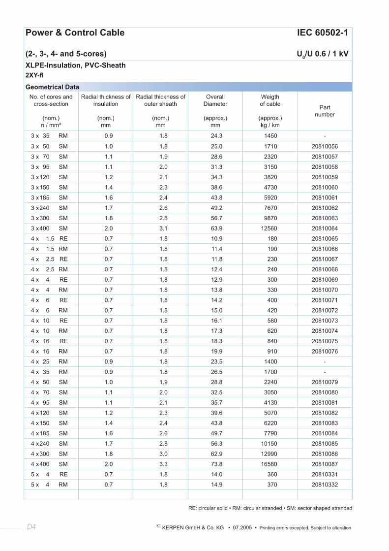
(2-, 3-, 4- and 5-cores) U0/U 0.6 / 1 kVXLPE-Insulation, PVC-Sheath2XY-fl
Geometrical DataNo. of cores and
cross-section
(nom.) n / mm²
Radial thickness of insulation
(nom.) mm
Radial thickness of outer sheath
(nom.) mm
Overall Diameter
(approx.) mm
Weigth of cable
(approx.) kg / km
Part number
3 x 35 RM 0.9 1.8 24.3 1450 -
3 x 50 SM 1.0 1.8 25.0 1710 20810056
3 x 70 SM 1.1 1.9 28.6 2320 20810057
3 x 95 SM 1.1 2.0 31.3 3150 20810058
3 x 120 SM 1.2 2.1 34.3 3820 20810059
3 x 150 SM 1.4 2.3 38.6 4730 20810060
3 x 185 SM 1.6 2.4 43.8 5920 20810061
3 x 240 SM 1.7 2.6 49.2 7670 20810062
3 x 300 SM 1.8 2.8 56.7 9870 20810063
3 x 400 SM 2.0 3.1 63.9 12560 20810064
4 x 1.5 RE 0.7 1.8 10.9 180 20810065
4 x 1.5 RM 0.7 1.8 11.4 190 20810066
4 x 2.5 RE 0.7 1.8 11.8 230 20810067
4 x 2.5 RM 0.7 1.8 12.4 240 20810068
4 x 4 RE 0.7 1.8 12.9 300 20810069
4 x 4 RM 0.7 1.8 13.8 330 20810070
4 x 6 RE 0.7 1.8 14.2 400 20810071
4 x 6 RM 0.7 1.8 15.0 420 20810072
4 x 10 RE 0.7 1.8 16.1 580 20810073
4 x 10 RM 0.7 1.8 17.3 620 20810074
4 x 16 RE 0.7 1.8 18.3 840 20810075
4 x 16 RM 0.7 1.8 19.9 910 20810076
4 x 25 RM 0.9 1.8 23.5 1400 -
4 x 35 RM 0.9 1.8 26.5 1700 -
4 x 50 SM 1.0 1.9 28.8 2240 20810079
4 x 70 SM 1.1 2.0 32.5 3050 20810080
4 x 95 SM 1.1 2.1 35.7 4130 20810081
4 x 120 SM 1.2 2.3 39.6 5070 20810082
4 x 150 SM 1.4 2.4 43.8 6220 20810083
4 x 185 SM 1.6 2.6 49.7 7790 20810084
4 x 240 SM 1.7 2.8 56.3 10150 20810085
4 x 300 SM 1.8 3.0 62.9 12990 20810086
4 x 400 SM 2.0 3.3 73.8 16580 20810087
5 x 4 RE 0.7 1.8 14.0 360 20810331
5 x 4 RM 0.7 1.8 14.9 370 20810332
RE: circular solid • RM: circular stranded • SM: sector shaped stranded
© KERPEN GmbH & Co. KG • 07.2005 • Printing errors excepted. Subject to alteration D5
Power & Control Cable IEC 60502-1
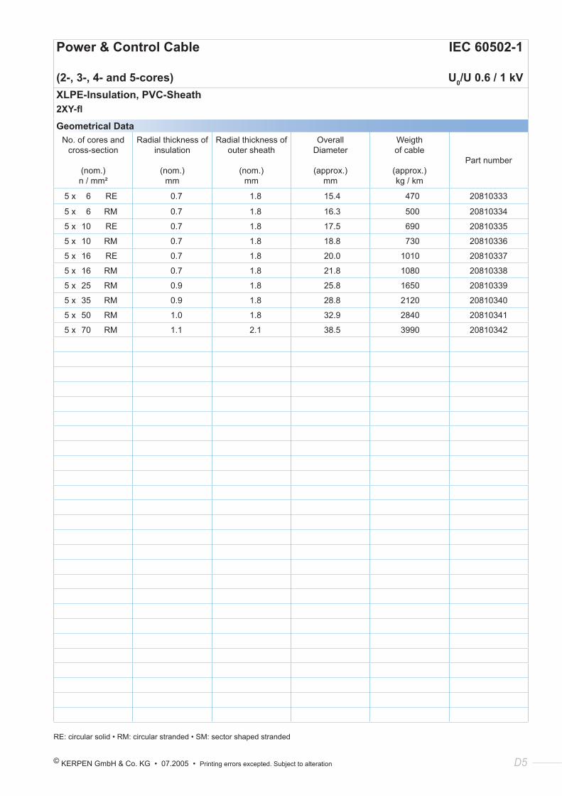
(2-, 3-, 4- and 5-cores) U0/U 0.6 / 1 kVXLPE-Insulation, PVC-Sheath2XY-fl
Geometrical DataNo. of cores and
cross-section
(nom.) n / mm²
Radial thickness of insulation
(nom.) mm
Radial thickness of outer sheath
(nom.) mm
Overall Diameter
(approx.) mm
Weigth of cable
(approx.) kg / km
Part number
5 x 6 RE 0.7 1.8 15.4 470 20810333
5 x 6 RM 0.7 1.8 16.3 500 20810334
5 x 10 RE 0.7 1.8 17.5 690 20810335
5 x 10 RM 0.7 1.8 18.8 730 20810336
5 x 16 RE 0.7 1.8 20.0 1010 20810337
5 x 16 RM 0.7 1.8 21.8 1080 20810338
5 x 25 RM 0.9 1.8 25.8 1650 20810339
5 x 35 RM 0.9 1.8 28.8 2120 20810340
5 x 50 RM 1.0 1.8 32.9 2840 20810341
5 x 70 RM 1.1 2.1 38.5 3990 20810342
RE: circular solid • RM: circular stranded • SM: sector shaped stranded
D6 KERPEN GmbH & Co. KG • 07.2005 • Printing errors excepted. Subject to alteration
Power & Control Cable IEC 60502-1
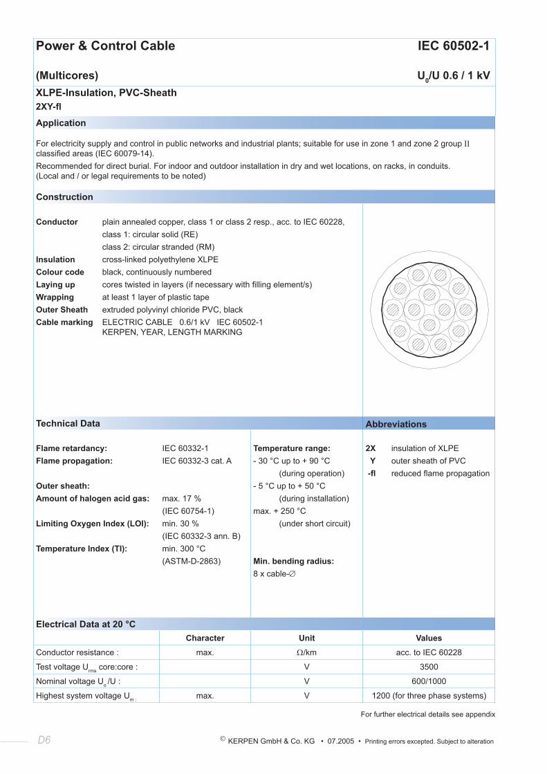
(Multicores) U0/U 0.6 / 1 kVXLPE-Insulation, PVC-Sheath2XY-fl
Application
For electricity supply and control in public networks and industrial plants; suitable for use in zone 1 and zone 2 group ΙΙ classified areas (IEC 60079-14).Recommended for direct burial. For indoor and outdoor installation in dry and wet locations, on racks, in conduits. (Local and / or legal requirements to be noted)
Construction
Conductor plain annealed copper, class 1 or class 2 resp., acc. to IEC 60228, class 1: circular solid (RE) class 2: circular stranded (RM)Insulation cross-linked polyethylene XLPEColour code black, continuously numberedLaying up cores twisted in layers (if necessary with filling element/s)Wrapping at least 1 layer of plastic tapeOuter Sheath extruded polyvinyl chloride PVC, blackCable marking ELECTRIC CABLE 0.6/1 kV IEC 60502-1 KERPEN, YEAR, LENGTH MARKING
Technical Data Abbreviations
Flame retardancy:Flame propagation:
Outer sheath:Amount of halogen acid gas:
Limiting Oxygen Index (LOI):
Temperature Index (TI):
IEC 60332-1IEC 60332-3 cat. A
max. 17 %(IEC 60754-1)min. 30 %(IEC 60332-3 ann. B)min. 300 °C(ASTM-D-2863)
Temperature range:- 30 °C up to + 90 °C (during operation)- 5 °C up to + 50 °C (during installation)max. + 250 °C (under short circuit)
Min. bending radius:8 x cable-∅
2X insulation of XLPE Y outer sheath of PVC -fl reduced flame propagation
Electrical Data at 20 °CCharacter Unit Values
Conductor resistance : max. Ω/km acc. to IEC 60228
Test voltage Urms core:core : V 3500
Nominal voltage Uo /U : V 600/1000
Highest system voltage Um : max. V 1200 (for three phase systems)
For further electrical details see appendix

© KERPEN GmbH & Co. KG • 07.2005 • Printing errors excepted. Subject to alteration D7
Power & Control Cable IEC 60502-1
(Multicores) U0/U 0.6 / 1 kVXLPE-Insulation, PVC-Sheath2XY-fl
Geometrical DataNo. of cores and
cross-section
(nom.) n / mm²
Radial thickness of insulation
(nom.) mm
Radial thickness of outer sheath
(nom.) mm
Overall Diameter
(approx.) mm
Weigth of cable
(approx.) kg / km
Part number
5 x 1.5 RE 0.7 1.8 11.3 180 20810131
7 x 1.5 RE 0.7 1.8 12.2 220 20810132
10 x 1.5 RE 0.7 1.8 14.9 310 20810133
12 x 1.5 RE 0.7 1.8 15.3 340 20810134
19 x 1.5 RE 0.7 1.8 17.7 480 20810137
27 x 1.5 RE 0.7 1.8 21.0 660 20810140
37 x 1.5 RE 0.7 1.8 23.4 860 20810144
48 x 1.5 RE 0.7 1.8 26.5 1080 20810148
5 x 1.5 RM 0.7 1.8 11.9 190 20810150
7 x 1.5 RM 0.7 1.8 12.8 230 20810151
10 x 1.5 RM 0.7 1.8 15.8 320 20810152
12 x 1.5 RM 0.7 1.8 16.2 360 20810153
19 x 1.5 RM 0.7 1.8 18.8 510 20810156
27 x 1.5 RM 0.7 1.8 22.3 700 20810108
37 x 1.5 RM 0.7 1.8 24.8 910 20810112
48 x 1.5 RM 0.7 1.8 28.3 1150 20810164
5 x 2.5 RE 0.7 1.8 12.4 240 20810351
7 x 2.5 RE 0.7 1.8 13.4 300 20810167
10 x 2.5 RE 0.7 1.8 16.4 400 20810168
12 x 2.5 RE 0.7 1.8 16.9 460 20810169
19 x 2.5 RE 0.7 1.8 19.8 670 20810172
27 x 2.5 RE 0.7 1.8 23.4 920 20810175
37 x 2.5 RE 0.7 1.8 26.1 1210 20810179
48 x 2.5 RE 0.7 1.9 29.9 1550 20810183
5 x 2.5 RM 0.7 1.8 13.0 250 20810115
7 x 2.5 RM 0.7 1.8 14.0 310 20810207
10 x 2.5 RM 0.7 1.8 17.4 420 20810116
12 x 2.5 RM 0.7 1.8 18.0 490 20810186
19 x 2.5 RM 0.7 1.8 21.0 710 20810189
27 x 2.5 RM 0.7 1.8 24.9 980 20810192
37 x 2.5 RM 0.7 1.8 27.8 1290 20810196
48 x 2.5 RM 0.7 1.9 31.9 1650 20810200
RE: circular solid • RM: circular stranded • SM: sector shaped stranded
D8 KERPEN GmbH & Co. KG • 07.2005 • Printing errors excepted. Subject to alteration
Power & Control Cable IEC 60502-1
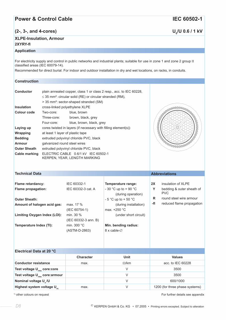
(2-, 3-, and 4-cores) U0/U 0.6 / 1 kVXLPE-Insulation, Armour2XYRY-flApplication
For electricity supply and control in public networks and industrial plants; suitable for use in zone 1 and zone 2 group ΙΙ classified areas (IEC 60079-14).Recommended for direct burial. For indoor and outdoor installation in dry and wet locations, on racks, in conduits.
Construction
Conductor plain annealed copper, class 1 or class 2 resp., acc. to IEC 60228, ≤ 35 mm²: circular solid (RE) or circular stranded (RM), > 35 mm²: sector-shaped stranded (SM)Insulation cross-linked polyethylene XLPEColour code Two-core: blue, brown Three-core: brown, black, grey Four-core: blue, brown, black, greyLaying up cores twisted in layers (if necessary with filling element(s))Wrapping at least 1 layer of plastic tapeBedding extruded polyvinyl chloride PVC, blackArmour galvanized round steel wiresOuter Sheath extruded polyvinyl chloride PVC, blackCable marking ELECTRIC CABLE 0.6/1 kV IEC 60502-1 KERPEN, YEAR, LENGTH MARKING
Technical Data Abbreviations
Flame retardancy:Flame propagation:
Outer Sheath:Amount of halogen acid gas:
Limiting Oxygen Index (LOI):
Temperature Index (TI):
IEC 60332-1IEC 60332-3 cat. A
max. 17 %(IEC 60754-1)min. 30 %(IEC 60332-3 ann. B)min. 300 °C(ASTM-D-2863)
Temperature range:- 30 °C up to + 90 °C (during operation)- 5 °C up to + 50 °C (during installation)max. +250 °C (under short circuit)
Min. bending radius:8 x cable-∅
2X insulation of XLPE Y bedding & outer sheath of PVC R round steel wire armour -fl reduced flame propagation
Electrical Data at 20 °CCharacter Unit Values
Conductor resistance max. Ω/km acc. to IEC 60228
Test voltage Urms core:core V 3500
Test voltage Urms core:armour V 3500
Nominal voltage Uo /U V 600/1000
Highest system voltage Um: max. V 1200 (for three phase systems)
1) other colours on request For further details see appendix
© KERPEN GmbH & Co. KG • 07.2005 • Printing errors excepted. Subject to alteration D9
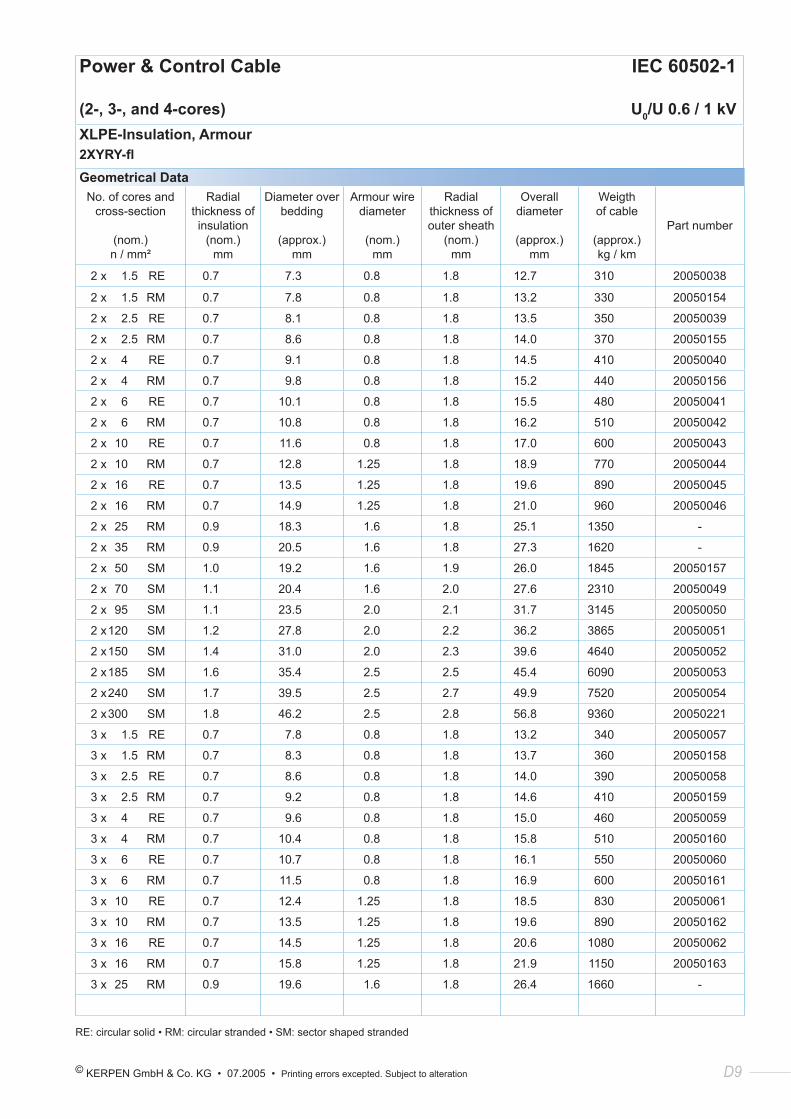
Power & Control Cable IEC 60502-1
(2-, 3-, and 4-cores) U0/U 0.6 / 1 kVXLPE-Insulation, Armour2XYRY-flGeometrical Data
No. of cores and cross-section
(nom.) n / mm²
Radial thickness of insulation
(nom.) mm
Diameter over bedding
(approx.) mm
Armour wire diameter
(nom.) mm
Radial thickness of outer sheath
(nom.) mm
Overall diameter
(approx.)
mm
Weigth of cable
(approx.) kg / km
Part number
2 x 1.5 RE 0.7 7.3 0.8 1.8 12.7 310 20050038
2 x 1.5 RM 0.7 7.8 0.8 1.8 13.2 330 20050154
2 x 2.5 RE 0.7 8.1 0.8 1.8 13.5 350 20050039
2 x 2.5 RM 0.7 8.6 0.8 1.8 14.0 370 20050155
2 x 4 RE 0.7 9.1 0.8 1.8 14.5 410 20050040
2 x 4 RM 0.7 9.8 0.8 1.8 15.2 440 20050156
2 x 6 RE 0.7 10.1 0.8 1.8 15.5 480 20050041
2 x 6 RM 0.7 10.8 0.8 1.8 16.2 510 20050042
2 x 10 RE 0.7 11.6 0.8 1.8 17.0 600 20050043
2 x 10 RM 0.7 12.8 1.25 1.8 18.9 770 20050044
2 x 16 RE 0.7 13.5 1.25 1.8 19.6 890 20050045
2 x 16 RM 0.7 14.9 1.25 1.8 21.0 960 20050046
2 x 25 RM 0.9 18.3 1.6 1.8 25.1 1350 -
2 x 35 RM 0.9 20.5 1.6 1.8 27.3 1620 -
2 x 50 SM 1.0 19.2 1.6 1.9 26.0 1845 20050157
2 x 70 SM 1.1 20.4 1.6 2.0 27.6 2310 20050049
2 x 95 SM 1.1 23.5 2.0 2.1 31.7 3145 20050050
2 x 120 SM 1.2 27.8 2.0 2.2 36.2 3865 20050051
2 x 150 SM 1.4 31.0 2.0 2.3 39.6 4640 20050052
2 x 185 SM 1.6 35.4 2.5 2.5 45.4 6090 20050053
2 x 240 SM 1.7 39.5 2.5 2.7 49.9 7520 20050054
2 x 300 SM 1.8 46.2 2.5 2.8 56.8 9360 20050221
3 x 1.5 RE 0.7 7.8 0.8 1.8 13.2 340 20050057
3 x 1.5 RM 0.7 8.3 0.8 1.8 13.7 360 20050158
3 x 2.5 RE 0.7 8.6 0.8 1.8 14.0 390 20050058
3 x 2.5 RM 0.7 9.2 0.8 1.8 14.6 410 20050159
3 x 4 RE 0.7 9.6 0.8 1.8 15.0 460 20050059
3 x 4 RM 0.7 10.4 0.8 1.8 15.8 510 20050160
3 x 6 RE 0.7 10.7 0.8 1.8 16.1 550 20050060
3 x 6 RM 0.7 11.5 0.8 1.8 16.9 600 20050161
3 x 10 RE 0.7 12.4 1.25 1.8 18.5 830 20050061
3 x 10 RM 0.7 13.5 1.25 1.8 19.6 890 20050162
3 x 16 RE 0.7 14.5 1.25 1.8 20.6 1080 20050062
3 x 16 RM 0.7 15.8 1.25 1.8 21.9 1150 20050163
3 x 25 RM 0.9 19.6 1.6 1.8 26.4 1660 -
RE: circular solid • RM: circular stranded • SM: sector shaped stranded
D10 KERPEN GmbH & Co. KG • 07.2005 • Printing errors excepted. Subject to alteration
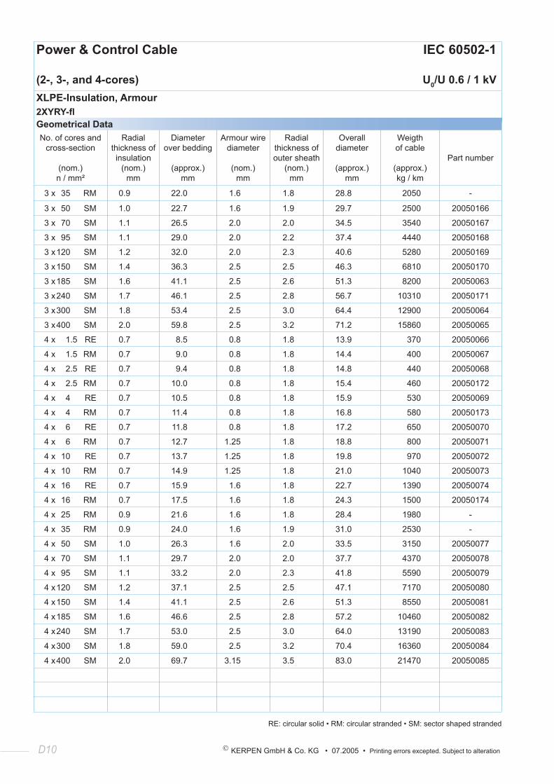
Power & Control Cable IEC 60502-1
(2-, 3-, and 4-cores) U0/U 0.6 / 1 kVXLPE-Insulation, Armour2XYRY-flGeometrical DataNo. of cores and
cross-section
(nom.) n / mm²
Radial thickness of insulation
(nom.) mm
Diameter over bedding
(approx.) mm
Armour wire diameter
(nom.) mm
Radial thickness of outer sheath
(nom.) mm
Overall diameter
(approx.)
mm
Weigth of cable
(approx.) kg / km
Part number
3 x 35 RM 0.9 22.0 1.6 1.8 28.8 2050 -
3 x 50 SM 1.0 22.7 1.6 1.9 29.7 2500 20050166
3 x 70 SM 1.1 26.5 2.0 2.0 34.5 3540 20050167
3 x 95 SM 1.1 29.0 2.0 2.2 37.4 4440 20050168
3 x 120 SM 1.2 32.0 2.0 2.3 40.6 5280 20050169
3 x 150 SM 1.4 36.3 2.5 2.5 46.3 6810 20050170
3 x 185 SM 1.6 41.1 2.5 2.6 51.3 8200 20050063
3 x 240 SM 1.7 46.1 2.5 2.8 56.7 10310 20050171
3 x 300 SM 1.8 53.4 2.5 3.0 64.4 12900 20050064
3 x 400 SM 2.0 59.8 2.5 3.2 71.2 15860 20050065
4 x 1.5 RE 0.7 8.5 0.8 1.8 13.9 370 20050066
4 x 1.5 RM 0.7 9.0 0.8 1.8 14.4 400 20050067
4 x 2.5 RE 0.7 9.4 0.8 1.8 14.8 440 20050068
4 x 2.5 RM 0.7 10.0 0.8 1.8 15.4 460 20050172
4 x 4 RE 0.7 10.5 0.8 1.8 15.9 530 20050069
4 x 4 RM 0.7 11.4 0.8 1.8 16.8 580 20050173
4 x 6 RE 0.7 11.8 0.8 1.8 17.2 650 20050070
4 x 6 RM 0.7 12.7 1.25 1.8 18.8 800 20050071
4 x 10 RE 0.7 13.7 1.25 1.8 19.8 970 20050072
4 x 10 RM 0.7 14.9 1.25 1.8 21.0 1040 20050073
4 x 16 RE 0.7 15.9 1.6 1.8 22.7 1390 20050074
4 x 16 RM 0.7 17.5 1.6 1.8 24.3 1500 20050174
4 x 25 RM 0.9 21.6 1.6 1.8 28.4 1980 -
4 x 35 RM 0.9 24.0 1.6 1.9 31.0 2530 -
4 x 50 SM 1.0 26.3 1.6 2.0 33.5 3150 20050077
4 x 70 SM 1.1 29.7 2.0 2.0 37.7 4370 20050078
4 x 95 SM 1.1 33.2 2.0 2.3 41.8 5590 20050079
4 x 120 SM 1.2 37.1 2.5 2.5 47.1 7170 20050080
4 x 150 SM 1.4 41.1 2.5 2.6 51.3 8550 20050081
4 x 185 SM 1.6 46.6 2.5 2.8 57.2 10460 20050082
4 x 240 SM 1.7 53.0 2.5 3.0 64.0 13190 20050083
4 x 300 SM 1.8 59.0 2.5 3.2 70.4 16360 20050084
4 x 400 SM 2.0 69.7 3.15 3.5 83.0 21470 20050085
RE: circular solid • RM: circular stranded • SM: sector shaped stranded
© KERPEN GmbH & Co. KG • 07.2005 • Printing errors excepted. Subject to alteration D11
KERPEN’s Focus:
Competence - Flexibility - Quality - Service
Flexibility
• new designs to customer required standards
• short delivery times to meet your project plan
• equipped for „short length“ production
• fast response to customer needs
• general purpose production equipment to manufacture large variety of products
D12 KERPEN GmbH & Co. KG • 07.2005 • Printing errors excepted. Subject to alteration
Power & Control Cable IEC 60502-1
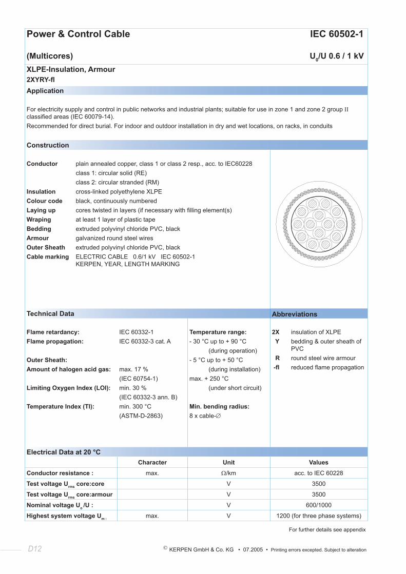
(Multicores) U0/U 0.6 / 1 kVXLPE-Insulation, Armour2XYRY-flApplication
For electricity supply and control in public networks and industrial plants; suitable for use in zone 1 and zone 2 group ΙΙ classified areas (IEC 60079-14).Recommended for direct burial. For indoor and outdoor installation in dry and wet locations, on racks, in conduits
Construction
Conductor plain annealed copper, class 1 or class 2 resp., acc. to IEC60228 class 1: circular solid (RE) class 2: circular stranded (RM)Insulation cross-linked polyethylene XLPEColour code black, continuously numberedLaying up cores twisted in layers (if necessary with filling element(s)Wraping at least 1 layer of plastic tapeBedding extruded polyvinyl chloride PVC, blackArmour galvanized round steel wiresOuter Sheath extruded polyvinyl chloride PVC, blackCable marking ELECTRIC CABLE 0.6/1 kV IEC 60502-1 KERPEN, YEAR, LENGTH MARKING
Technical Data Abbreviations
Flame retardancy:Flame propagation:
Outer Sheath:Amount of halogen acid gas:
Limiting Oxygen Index (LOI):
Temperature Index (TI):
IEC 60332-1IEC 60332-3 cat. A
max. 17 %(IEC 60754-1)min. 30 %(IEC 60332-3 ann. B)min. 300 °C(ASTM-D-2863)
Temperature range:- 30 °C up to + 90 °C (during operation)- 5 °C up to + 50 °C (during installation)max. + 250 °C (under short circuit)
Min. bending radius:8 x cable-∅
2X insulation of XLPE Y bedding & outer sheath of PVC R round steel wire armour -fl reduced flame propagation
Electrical Data at 20 °CCharacter Unit Values
Conductor resistance : max. Ω/km acc. to IEC 60228
Test voltage Urms core:core V 3500
Test voltage Urms core:armour V 3500
Nominal voltage Uo /U : V 600/1000
Highest system voltage Um : max. V 1200 (for three phase systems)
For further details see appendix
© KERPEN GmbH & Co. KG • 07.2005 • Printing errors excepted. Subject to alteration D13
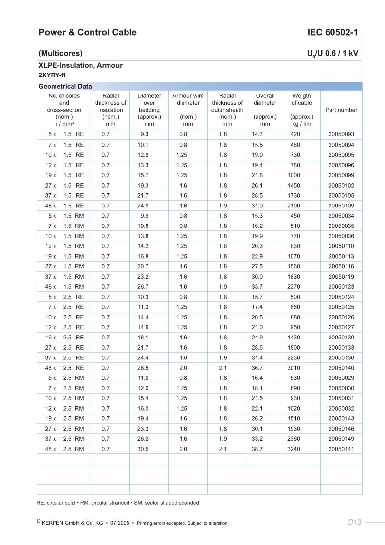
Power & Control Cable IEC 60502-1
(Multicores) U0/U 0.6 / 1 kVXLPE-Insulation, Armour2XYRY-flGeometrical Data
No. of cores and
cross-section(nom.) n / mm²
Radial thickness of insulation
(nom.) mm
Diameter over
bedding(approx.)
mm
Armour wire diameter
(nom.) mm
Radial thickness of outer sheath
(nom.) mm
Overall diameter
(approx.) mm
Weigth of cable
(approx.) kg / km
Part number
5 x 1.5 RE 0.7 9.3 0.8 1.8 14.7 420 20050093
7 x 1.5 RE 0.7 10.1 0.8 1.8 15.5 480 20050094
10 x 1.5 RE 0.7 12.9 1.25 1.8 19.0 730 20050095
12 x 1.5 RE 0.7 13.3 1.25 1.8 19.4 780 20050096
19 x 1.5 RE 0.7 15.7 1.25 1.8 21.8 1000 20050099
27 x 1.5 RE 0.7 19.3 1.6 1.8 26.1 1450 20050102
37 x 1.5 RE 0.7 21.7 1.6 1.8 28.5 1730 20050105
48 x 1.5 RE 0.7 24.9 1.6 1.9 31.9 2100 20050109
5 x 1.5 RM 0.7 9.9 0.8 1.8 15.3 450 20050034
7 x 1.5 RM 0.7 10.8 0.8 1.8 16.2 510 20050035
10 x 1.5 RM 0.7 13.8 1.25 1.8 19.9 770 20050036
12 x 1.5 RM 0.7 14.2 1.25 1.8 20.3 830 20050110
19 x 1.5 RM 0.7 16.8 1.25 1.8 22.9 1070 20050113
27 x 1.5 RM 0.7 20.7 1.6 1.8 27.5 1560 20050116
37 x 1.5 RM 0.7 23.2 1.6 1.8 30.0 1830 20050119
48 x 1.5 RM 0.7 26.7 1.6 1.9 33.7 2270 20050123
5 x 2.5 RE 0.7 10.3 0.8 1.8 15.7 500 20050124
7 x 2.5 RE 0.7 11.3 1.25 1.8 17.4 660 20050125
10 x 2.5 RE 0.7 14.4 1.25 1.8 20.5 880 20050126
12 x 2.5 RE 0.7 14.9 1.25 1.8 21.0 950 20050127
19 x 2.5 RE 0.7 18.1 1.6 1.8 24.9 1430 20050130
27 x 2.5 RE 0.7 21.7 1.6 1.8 28.5 1800 20050133
37 x 2.5 RE 0.7 24.4 1.6 1.9 31.4 2230 20050136
48 x 2.5 RE 0.7 28.5 2.0 2.1 36.7 3010 20050140
5 x 2.5 RM 0.7 11.0 0.8 1.8 16.4 530 20050029
7 x 2.5 RM 0.7 12.0 1.25 1.8 18.1 690 20050030
10 x 2.5 RM 0.7 15.4 1.25 1.8 21.5 930 20050031
12 x 2.5 RM 0.7 16.0 1.25 1.8 22.1 1020 20050032
19 x 2.5 RM 0.7 19.4 1.6 1.8 26.2 1510 20050143
27 x 2.5 RM 0.7 23.3 1.6 1.8 30.1 1930 20050146
37 x 2.5 RM 0.7 26.2 1.6 1.9 33.2 2360 20050149
48 x 2.5 RM 0.7 30.5 2.0 2.1 38.7 3240 20050141
RE: circular solid • RM: circular stranded • SM: sector shaped stranded

D14 KERPEN GmbH & Co. KG • 07.2005 • Printing errors excepted. Subject to alteration
© KERPEN GmbH & Co. KG • 07.2005 • Printing errors excepted. Subject to alteration E1
Section 3:
Zero Halogen
Low Voltage Cables (90 °C)
U0 /U 0.6 / 1 kV
E2 KERPEN GmbH & Co. KG • 07.2005 • Printing errors excepted. Subject to alteration
Power & Control Cable IEC 60502-1
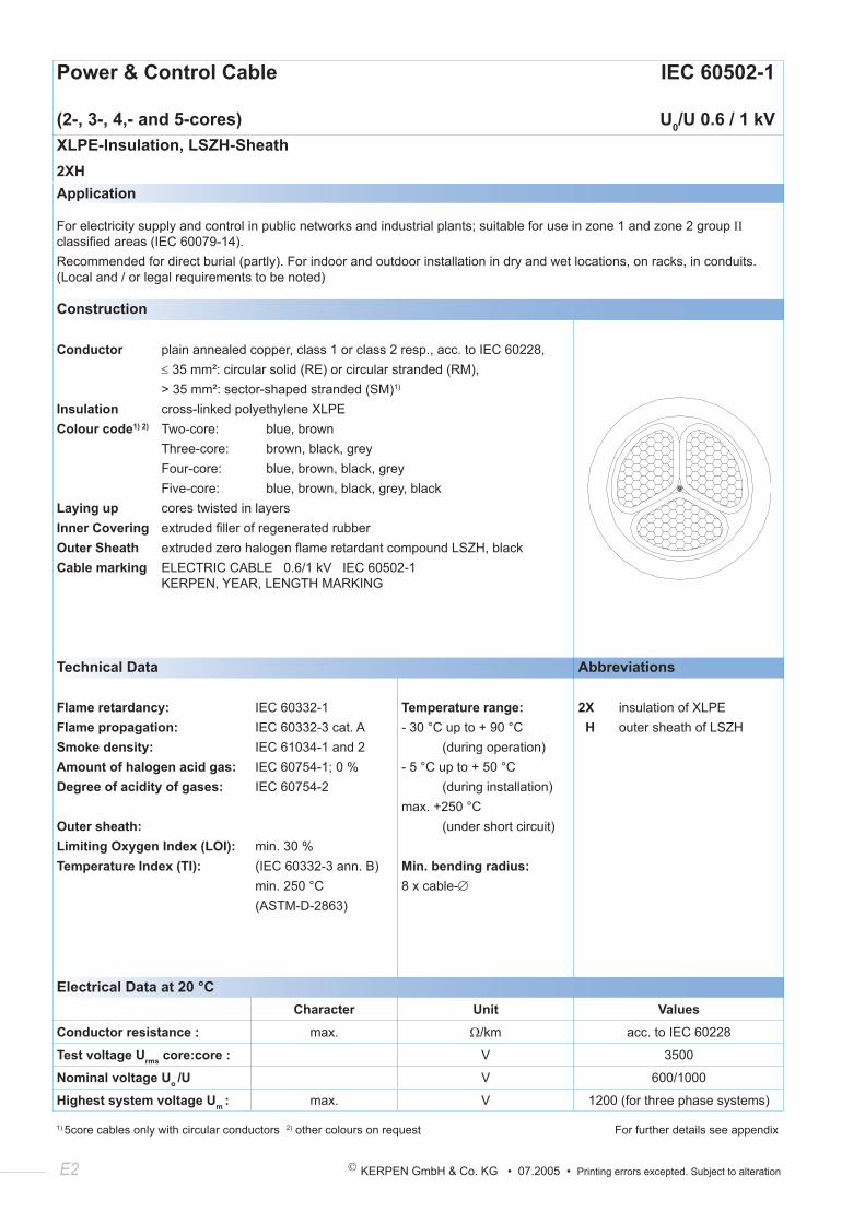
(2-, 3-, 4,- and 5-cores) U0/U 0.6 / 1 kVXLPE-Insulation, LSZH-Sheath2XHApplication
For electricity supply and control in public networks and industrial plants; suitable for use in zone 1 and zone 2 group ΙΙ classified areas (IEC 60079-14).Recommended for direct burial (partly). For indoor and outdoor installation in dry and wet locations, on racks, in conduits. (Local and / or legal requirements to be noted)
Construction
Conductor plain annealed copper, class 1 or class 2 resp., acc. to IEC 60228, ≤ 35 mm²: circular solid (RE) or circular stranded (RM), > 35 mm²: sector-shaped stranded (SM)1)
Insulation cross-linked polyethylene XLPEColour code1) 2) Two-core: blue, brown Three-core: brown, black, grey Four-core: blue, brown, black, grey Five-core: blue, brown, black, grey, blackLaying up cores twisted in layersInner Covering extruded filler of regenerated rubberOuter Sheath extruded zero halogen flame retardant compound LSZH, blackCable marking ELECTRIC CABLE 0.6/1 kV IEC 60502-1 KERPEN, YEAR, LENGTH MARKING
Technical Data Abbreviations
Flame retardancy:Flame propagation:Smoke density:Amount of halogen acid gas:Degree of acidity of gases:
Outer sheath:Limiting Oxygen Index (LOI):Temperature Index (TI):
IEC 60332-1IEC 60332-3 cat. AIEC 61034-1 and 2IEC 60754-1; 0 %IEC 60754-2
min. 30 %(IEC 60332-3 ann. B)min. 250 °C(ASTM-D-2863)
Temperature range:- 30 °C up to + 90 °C (during operation)- 5 °C up to + 50 °C (during installation)max. +250 °C (under short circuit)
Min. bending radius:8 x cable-∅
2X insulation of XLPE H outer sheath of LSZH
Electrical Data at 20 °CCharacter Unit Values
Conductor resistance : max. Ω/km acc. to IEC 60228
Test voltage Urms core:core : V 3500
Nominal voltage Uo /U V 600/1000
Highest system voltage Um : max. V 1200 (for three phase systems)
1) 5core cables only with circular conductors 2) other colours on request For further details see appendix
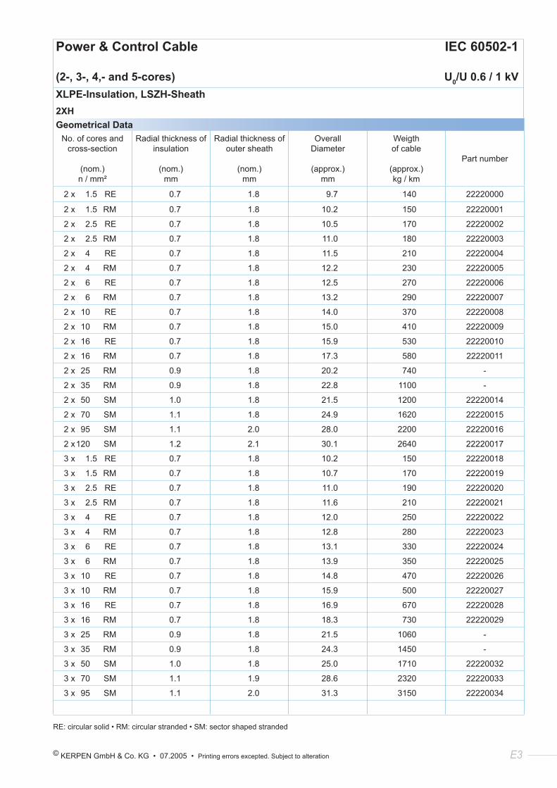
© KERPEN GmbH & Co. KG • 07.2005 • Printing errors excepted. Subject to alteration E3
Power & Control Cable IEC 60502-1
(2-, 3-, 4,- and 5-cores) U0/U 0.6 / 1 kVXLPE-Insulation, LSZH-Sheath2XHGeometrical Data
No. of cores and cross-section
(nom.) n / mm²
Radial thickness of insulation
(nom.)
mm
Radial thickness of outer sheath
(nom.)
mm
Overall Diameter
(approx.) mm
Weigth of cable
(approx.) kg / km
Part number
2 x 1.5 RE 0.7 1.8 9.7 140 22220000
2 x 1.5 RM 0.7 1.8 10.2 150 22220001
2 x 2.5 RE 0.7 1.8 10.5 170 22220002
2 x 2.5 RM 0.7 1.8 11.0 180 22220003
2 x 4 RE 0.7 1.8 11.5 210 22220004
2 x 4 RM 0.7 1.8 12.2 230 22220005
2 x 6 RE 0.7 1.8 12.5 270 22220006
2 x 6 RM 0.7 1.8 13.2 290 22220007
2 x 10 RE 0.7 1.8 14.0 370 22220008
2 x 10 RM 0.7 1.8 15.0 410 22220009
2 x 16 RE 0.7 1.8 15.9 530 22220010
2 x 16 RM 0.7 1.8 17.3 580 22220011
2 x 25 RM 0.9 1.8 20.2 740 -
2 x 35 RM 0.9 1.8 22.8 1100 -
2 x 50 SM 1.0 1.8 21.5 1200 22220014
2 x 70 SM 1.1 1.8 24.9 1620 22220015
2 x 95 SM 1.1 2.0 28.0 2200 22220016
2 x 120 SM 1.2 2.1 30.1 2640 22220017
3 x 1.5 RE 0.7 1.8 10.2 150 22220018
3 x 1.5 RM 0.7 1.8 10.7 170 22220019
3 x 2.5 RE 0.7 1.8 11.0 190 22220020
3 x 2.5 RM 0.7 1.8 11.6 210 22220021
3 x 4 RE 0.7 1.8 12.0 250 22220022
3 x 4 RM 0.7 1.8 12.8 280 22220023
3 x 6 RE 0.7 1.8 13.1 330 22220024
3 x 6 RM 0.7 1.8 13.9 350 22220025
3 x 10 RE 0.7 1.8 14.8 470 22220026
3 x 10 RM 0.7 1.8 15.9 500 22220027
3 x 16 RE 0.7 1.8 16.9 670 22220028
3 x 16 RM 0.7 1.8 18.3 730 22220029
3 x 25 RM 0.9 1.8 21.5 1060 -
3 x 35 RM 0.9 1.8 24.3 1450 -
3 x 50 SM 1.0 1.8 25.0 1710 22220032
3 x 70 SM 1.1 1.9 28.6 2320 22220033
3 x 95 SM 1.1 2.0 31.3 3150 22220034
RE: circular solid • RM: circular stranded • SM: sector shaped stranded
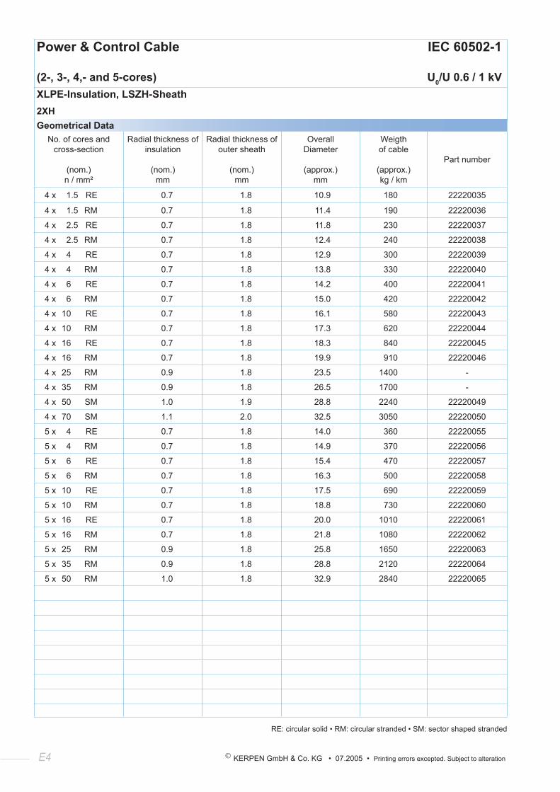
E4 KERPEN GmbH & Co. KG • 07.2005 • Printing errors excepted. Subject to alteration
Power & Control Cable IEC 60502-1
(2-, 3-, 4,- and 5-cores) U0/U 0.6 / 1 kVXLPE-Insulation, LSZH-Sheath2XHGeometrical Data
No. of cores and cross-section
(nom.) n / mm²
Radial thickness of insulation
(nom.) mm
Radial thickness of outer sheath
(nom.) mm
Overall Diameter
(approx.) mm
Weigth of cable
(approx.) kg / km
Part number
4 x 1.5 RE 0.7 1.8 10.9 180 22220035
4 x 1.5 RM 0.7 1.8 11.4 190 22220036
4 x 2.5 RE 0.7 1.8 11.8 230 22220037
4 x 2.5 RM 0.7 1.8 12.4 240 22220038
4 x 4 RE 0.7 1.8 12.9 300 22220039
4 x 4 RM 0.7 1.8 13.8 330 22220040
4 x 6 RE 0.7 1.8 14.2 400 22220041
4 x 6 RM 0.7 1.8 15.0 420 22220042
4 x 10 RE 0.7 1.8 16.1 580 22220043
4 x 10 RM 0.7 1.8 17.3 620 22220044
4 x 16 RE 0.7 1.8 18.3 840 22220045
4 x 16 RM 0.7 1.8 19.9 910 22220046
4 x 25 RM 0.9 1.8 23.5 1400 -
4 x 35 RM 0.9 1.8 26.5 1700 -
4 x 50 SM 1.0 1.9 28.8 2240 22220049
4 x 70 SM 1.1 2.0 32.5 3050 22220050
5 x 4 RE 0.7 1.8 14.0 360 22220055
5 x 4 RM 0.7 1.8 14.9 370 22220056
5 x 6 RE 0.7 1.8 15.4 470 22220057
5 x 6 RM 0.7 1.8 16.3 500 22220058
5 x 10 RE 0.7 1.8 17.5 690 22220059
5 x 10 RM 0.7 1.8 18.8 730 22220060
5 x 16 RE 0.7 1.8 20.0 1010 22220061
5 x 16 RM 0.7 1.8 21.8 1080 22220062
5 x 25 RM 0.9 1.8 25.8 1650 22220063
5 x 35 RM 0.9 1.8 28.8 2120 22220064
5 x 50 RM 1.0 1.8 32.9 2840 22220065
RE: circular solid • RM: circular stranded • SM: sector shaped stranded
© KERPEN GmbH & Co. KG • 07.2005 • Printing errors excepted. Subject to alteration E5
KERPEN’s Focus:
Competence - Flexibility - Quality - Service
Quality
• new designs to customer required standards
• one of the first with ISO 9001 certificate (1990) ISO 9001:2000 (2002)
• first cable manufacturer with ISO 14001 environment certificate (1998)
• test certificates for every drum length
• special certificates for fire resistant cables
• UL approvals, GOST certificates
• acceptance through inspection companies
E6 KERPEN GmbH & Co. KG • 07.2005 • Printing errors excepted. Subject to alteration
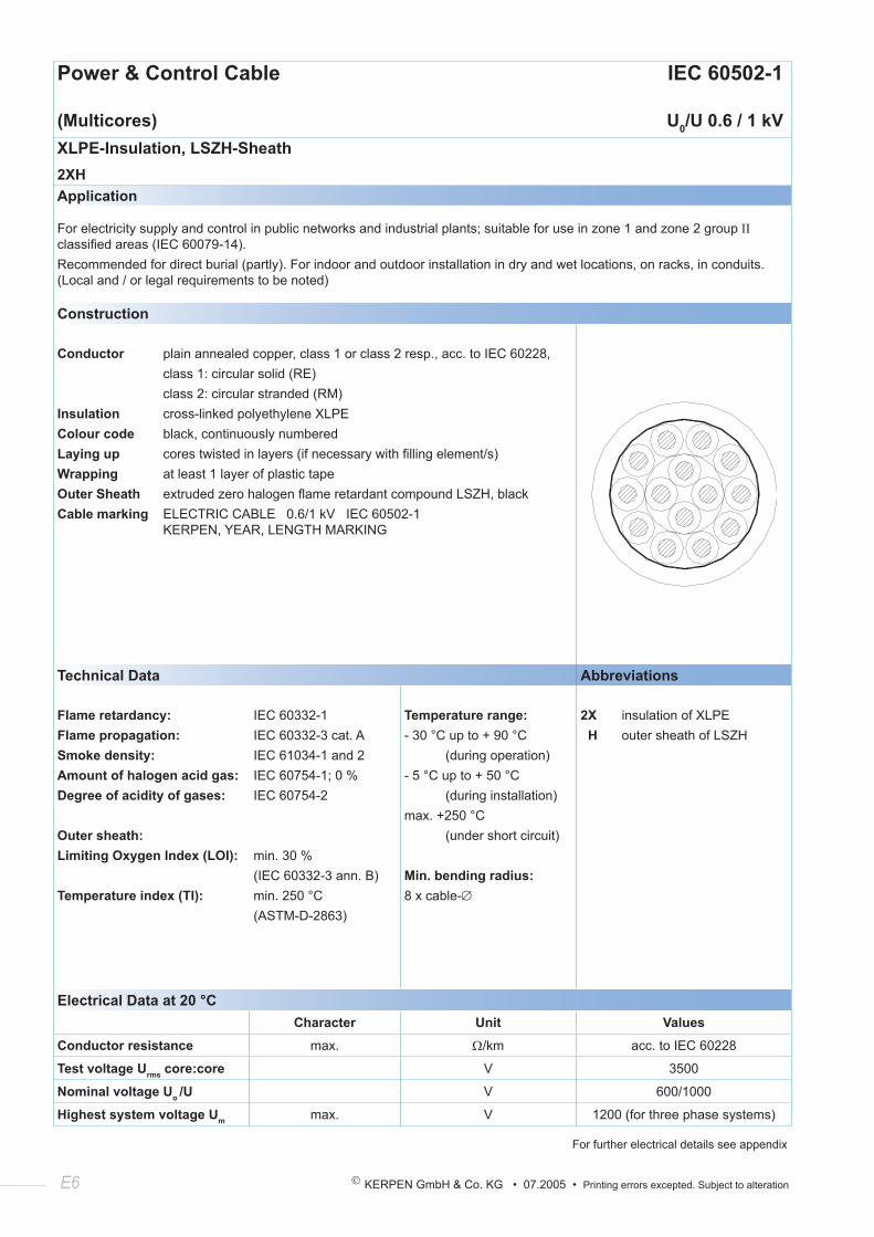
Power & Control Cable IEC 60502-1
(Multicores) U0/U 0.6 / 1 kVXLPE-Insulation, LSZH-Sheath2XHApplication
For electricity supply and control in public networks and industrial plants; suitable for use in zone 1 and zone 2 group ΙΙ classified areas (IEC 60079-14).Recommended for direct burial (partly). For indoor and outdoor installation in dry and wet locations, on racks, in conduits. (Local and / or legal requirements to be noted)
Construction
Conductor plain annealed copper, class 1 or class 2 resp., acc. to IEC 60228, class 1: circular solid (RE) class 2: circular stranded (RM)Insulation cross-linked polyethylene XLPEColour code black, continuously numberedLaying up cores twisted in layers (if necessary with filling element/s)Wrapping at least 1 layer of plastic tapeOuter Sheath extruded zero halogen flame retardant compound LSZH, blackCable marking ELECTRIC CABLE 0.6/1 kV IEC 60502-1 KERPEN, YEAR, LENGTH MARKING
Technical Data Abbreviations
Flame retardancy:Flame propagation:Smoke density:Amount of halogen acid gas:Degree of acidity of gases:
Outer sheath:Limiting Oxygen Index (LOI):
Temperature index (TI):
IEC 60332-1IEC 60332-3 cat. AIEC 61034-1 and 2IEC 60754-1; 0 %IEC 60754-2
min. 30 %(IEC 60332-3 ann. B)min. 250 °C(ASTM-D-2863)
Temperature range:- 30 °C up to + 90 °C (during operation)- 5 °C up to + 50 °C (during installation)max. +250 °C (under short circuit)
Min. bending radius:8 x cable-∅
2X insulation of XLPE H outer sheath of LSZH
Electrical Data at 20 °CCharacter Unit Values
Conductor resistance max. Ω/km acc. to IEC 60228
Test voltage Urms core:core V 3500
Nominal voltage Uo /U V 600/1000
Highest system voltage Um max. V 1200 (for three phase systems)
For further electrical details see appendix
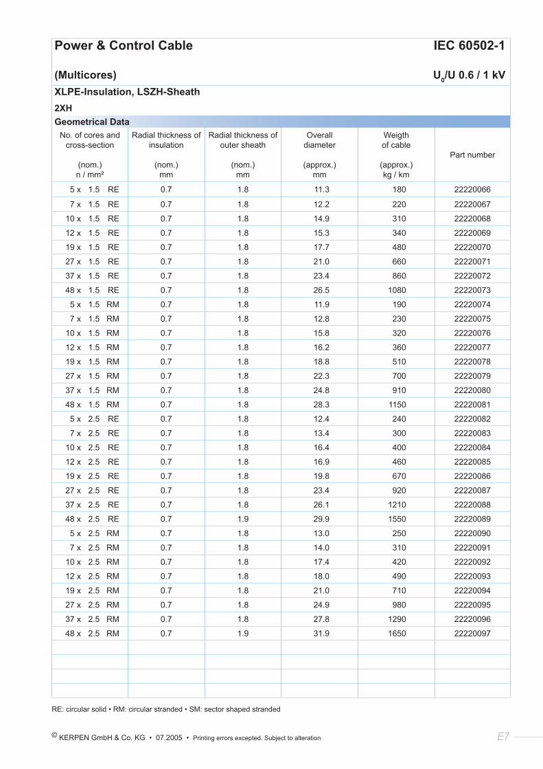
© KERPEN GmbH & Co. KG • 07.2005 • Printing errors excepted. Subject to alteration E7
Power & Control Cable IEC 60502-1
(Multicores) U0/U 0.6 / 1 kVXLPE-Insulation, LSZH-Sheath2XHGeometrical Data
No. of cores and cross-section
(nom.) n / mm²
Radial thickness of insulation
(nom.) mm
Radial thickness of outer sheath
(nom.) mm
Overall diameter
(approx.) mm
Weigth of cable
(approx.) kg / km
Part number
5 x 1.5 RE 0.7 1.8 11.3 180 22220066
7 x 1.5 RE 0.7 1.8 12.2 220 22220067
10 x 1.5 RE 0.7 1.8 14.9 310 22220068
12 x 1.5 RE 0.7 1.8 15.3 340 22220069
19 x 1.5 RE 0.7 1.8 17.7 480 22220070
27 x 1.5 RE 0.7 1.8 21.0 660 22220071
37 x 1.5 RE 0.7 1.8 23.4 860 22220072
48 x 1.5 RE 0.7 1.8 26.5 1080 22220073
5 x 1.5 RM 0.7 1.8 11.9 190 22220074
7 x 1.5 RM 0.7 1.8 12.8 230 22220075
10 x 1.5 RM 0.7 1.8 15.8 320 22220076
12 x 1.5 RM 0.7 1.8 16.2 360 22220077
19 x 1.5 RM 0.7 1.8 18.8 510 22220078
27 x 1.5 RM 0.7 1.8 22.3 700 22220079
37 x 1.5 RM 0.7 1.8 24.8 910 22220080
48 x 1.5 RM 0.7 1.8 28.3 1150 22220081
5 x 2.5 RE 0.7 1.8 12.4 240 22220082
7 x 2.5 RE 0.7 1.8 13.4 300 22220083
10 x 2.5 RE 0.7 1.8 16.4 400 22220084
12 x 2.5 RE 0.7 1.8 16.9 460 22220085
19 x 2.5 RE 0.7 1.8 19.8 670 22220086
27 x 2.5 RE 0.7 1.8 23.4 920 22220087
37 x 2.5 RE 0.7 1.8 26.1 1210 22220088
48 x 2.5 RE 0.7 1.9 29.9 1550 22220089
5 x 2.5 RM 0.7 1.8 13.0 250 22220090
7 x 2.5 RM 0.7 1.8 14.0 310 22220091
10 x 2.5 RM 0.7 1.8 17.4 420 22220092
12 x 2.5 RM 0.7 1.8 18.0 490 22220093
19 x 2.5 RM 0.7 1.8 21.0 710 22220094
27 x 2.5 RM 0.7 1.8 24.9 980 22220095
37 x 2.5 RM 0.7 1.8 27.8 1290 22220096
48 x 2.5 RM 0.7 1.9 31.9 1650 22220097
RE: circular solid • RM: circular stranded • SM: sector shaped stranded
E8 KERPEN GmbH & Co. KG • 07.2005 • Printing errors excepted. Subject to alteration
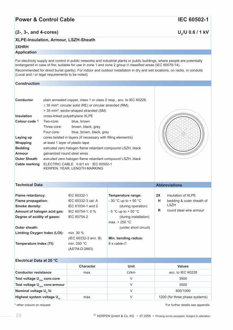
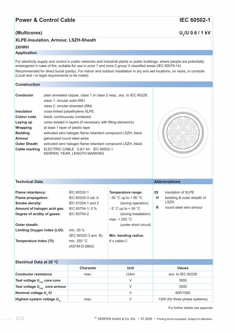
Power & Control Cable IEC 60502-1
(2-, 3-, and 4-cores) U0/U 0.6 / 1 kVXLPE-Insulation, Armour, LSZH-Sheath2XHRHApplication
For electricity supply and control in public networks and industrial plants or public buildings, where people are potentially endangered in case of fire; suitable for use in zone 1 and zone 2 group ΙΙ classified areas (IEC 60079-14).Recommended for direct burial (partly). For indoor and outdoor installation in dry and wet locations, on racks, in conduits (Local and / or legal requirements to be noted)
Construction
Conductor plain annealed copper, class 1 or class 2 resp., acc. to IEC 60228, ≤ 35 mm²: circular solid (RE) or circular stranded (RM), > 35 mm²: sector-shaped stranded (SM)Insulation cross-linked polyethylene XLPEColour code 1) Two-core: blue, brown Three-core: brown, black, grey Four-core: blue, brown, black, greyLaying up cores twisted in layers (if necessary with filling element/s)Wrapping at least 1 layer of plastic tapeBedding extruded zero halogen flame retardant compound LSZH, blackArmour galvanized round steel wiresOuter Sheath extruded zero halogen flame retardant compound LSZH, blackCable marking ELECTRIC CABLE 0.6/1 kV IEC 60502-1 KERPEN, YEAR, LENGTH MARKING
Technical Data Abbreviations
Flame retardancy:Flame propagation:Smoke density:Amount of halogen acid gas:Degree of acidity of gases:
Outer sheath:Limiting Oxygen Index (LOI):
Temperature Index (TI):
IEC 60332-1IEC 60332-3 cat. AIEC 61034-1 and 2IEC 60754-1; 0 %IEC 60754-2
min. 30 %(IEC 60332-3 ann. B)min. 250 °C(ASTM-D-2863)
Temperature range:- 30 °C up to + 90 °C (during operation)- 5 °C up to + 50 °C (during installation)max. + 250 °C (under short circuit)
Min. bending radius:8 x cable-∅
2X insulation of XLPE H bedding & outer sheath of LSZH R round steel wire armour
Electrical Data at 20 °CCharacter Unit Values
Conductor resistance max. Ω/km acc. to IEC 60228
Test voltage Urms core:core V 3500
Test voltage Urms core:armour V 3500
Nominal voltage Uo /U V 600/1000
Highest system voltage Um : max. V 1200 (for three phase systems)
1) other colours on request For further details see appendix
© KERPEN GmbH & Co. KG • 07.2005 • Printing errors excepted. Subject to alteration E9
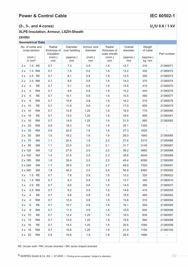
Power & Control Cable IEC 60502-1
(2-, 3-, and 4-cores) U0/U 0.6 / 1 kVXLPE-Insulation, Armour, LSZH-Sheath2XHRHGeometrical Data
No. of cores and cross-section
(nom.) n/ mm²
Radial thickness of insulation
(nom.) mm
Diameter over bedding
(approx.) mm
Armour wire diameter
(nom.) mm
Radial thickness of outer sheath
(nom.) mm
Overall diameter
(approx.) mm
Weigth of cable
(approx.) kg / km
Part number
2 x 1.5 RE 0.7 7.3 0.8 1.8 12.7 310 21380071
2 x 1.5 RM 0.7 7.8 0.8 1.8 13.2 330 21380072
2 x 2.5 RE 0.7 8.1 0.8 1.8 13.5 350 21380073
2 x 2.5 RM 0.7 8.6 0.8 1.8 14.0 370 21380074
2 x 4 RE 0.7 9.1 0.8 1.8 14.5 410 21380075
2 x 4 RM 0.7 9.8 0.8 1.8 15.2 440 21380076
2 x 6 RE 0.7 10.1 0.8 1.8 15.5 480 21380077
2 x 6 RM 0.7 10.8 0.8 1.8 16.2 510 21380078
2 x 10 RE 0.7 11.6 0.8 1.8 17.0 600 21380079
2 x 10 RM 0.7 12.8 1.25 1.8 18.9 770 21380080
2 x 16 RE 0.7 13.5 1.25 1.8 19.6 890 21380081
2 x 16 RM 0.7 14.9 1.25 1.8 21.0 960 21380082
2 x 25 RM 0.9 18.3 1.6 1.8 25.1 1350 -
2 x 35 RM 0.9 20.5 1.6 1.8 27.3 1620 -
2 x 50 SM 1.0 19.2 1.6 1.9 26.0 1845 21380085
2 x 70 SM 1.1 20.4 1.6 2.0 27.6 2310 21380086
2 x 95 SM 1.1 23.5 2.0 2.1 31.7 3145 21380087
2 x 120 SM 1.2 27.8 2.0 2.2 36.2 3865 21380088
2 x 150 SM 1.4 31.0 2.0 2.3 39.6 4640 21380089
2 x 185 SM 1.6 35.4 2.5 2.5 45.4 6090 21380090
2 x 240 SM 1.7 39.5 2.5 2.7 49.9 7520 21380091
2 x 300 SM 1.8 46.2 2.5 2.8 56.8 9360 21380092
3 x 1.5 RE 0.7 7.8 0.8 1.8 13.2 320 21380023
3 x 1.5 RM 0.7 8.3 0.8 1.8 13.7 340 21380010
3 x 2.5 RE 0.7 8.6 0.8 1.8 14.0 390 21380037
3 x 2.5 RM 0.7 9.2 0.8 1.8 14.6 410 21380050
3 x 4 RE 0.7 9.6 0.8 1.8 15.0 460 21380093
3 x 4 RM 0.7 10.4 0.8 1.8 15.8 510 21380094
3 x 6 RE 0.7 10.7 0.8 1.8 16.1 550 21380095
3 x 6 RM 0.7 11.5 0.8 1.8 16.9 600 21380096
3 x 10 RE 0.7 12.4 1.25 1.8 18.5 830 21380097
3 x 10 RM 0.7 13.5 1.25 1.8 19.6 890 21380098
3 x 16 RE 0.7 14.5 1.25 1.8 20.6 1080 21380099
3 x 16 RM 0.7 15.8 1.25 1.8 21.9 1150 21380100
3 x 25 RM 0.9 19.6 1.6 1.8 26.4 1660 -
RE: circular solid • RM: circular stranded • SM: sector shaped stranded
E10 KERPEN GmbH & Co. KG • 07.2005 • Printing errors excepted. Subject to alteration
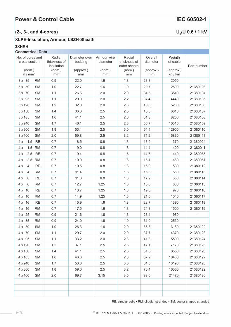
Power & Control Cable IEC 60502-1
(2-, 3-, and 4-cores) U0/U 0.6 / 1 kVXLPE-Insulation, Armour, LSZH-Sheath2XHRHGeometrical DataNo. of cores and
cross-section
(nom.) n / mm²
Radial thickness of insulation
(nom.) mm
Diameter over bedding
(approx.) mm
Armour wire diameter
(nom.)
mm
Radial thickness of outer sheath
(nom.) mm
Overall diameter
(approx.)
mm
Weigth of cable
(approx.) kg / km
Part number
3 x 35 RM 0.9 22.0 1.6 1.8 28.8 2050 -
3 x 50 SM 1.0 22.7 1.6 1.9 29.7 2500 21380103
3 x 70 SM 1.1 26.5 2.0 2.0 34.5 3540 21380104
3 x 95 SM 1.1 29.0 2.0 2.2 37.4 4440 21380105
3 x 120 SM 1.2 32.0 2.0 2.3 40.6 5280 21380106
3 x 150 SM 1.4 36.3 2.5 2.5 46.3 6810 21380107
3 x 185 SM 1.6 41.1 2.5 2.6 51.3 8200 21380108
3 x 240 SM 1.7 46.1 2.5 2.8 56.7 10310 21380109
3 x 300 SM 1.8 53.4 2.5 3.0 64.4 12900 21380110
3 x 400 SM 2.0 59.8 2.5 3.2 71.2 15860 21380111
4 x 1.5 RE 0.7 8.5 0.8 1.8 13.9 370 21380024
4 x 1.5 RM 0.7 9.0 0.8 1.8 14.4 400 21380011
4 x 2.5 RE 0.7 9.4 0.8 1.8 14.8 440 21380038
4 x 2.5 RM 0.7 10.0 0.8 1.8 15.4 460 21380051
4 x 4 RE 0.7 10.5 0.8 1.8 15.9 530 21380112
4 x 4 RM 0.7 11.4 0.8 1.8 16.8 580 21380113
4 x 6 RE 0.7 11.8 0.8 1.8 17.2 650 21380114
4 x 6 RM 0.7 12.7 1.25 1.8 18.8 800 21380115
4 x 10 RE 0.7 13.7 1.25 1.8 19.8 970 21380116
4 x 10 RM 0.7 14.9 1.25 1.8 21.0 1040 21380117
4 x 16 RE 0.7 15.9 1.6 1.8 22.7 1390 21380118
4 x 16 RM 0.7 17.5 1.6 1.8 24.3 1500 21380119
4 x 25 RM 0.9 21.6 1.6 1.8 28.4 1980 -
4 x 35 RM 0.9 24.0 1.6 1.9 31.0 2530 -
4 x 50 SM 1.0 26.3 1.6 2.0 33.5 3150 21380122
4 x 70 SM 1.1 29.7 2.0 2.0 37.7 4370 21380123
4 x 95 SM 1.1 33.2 2.0 2.3 41.8 5590 21380124
4 x 120 SM 1.2 37.1 2.5 2.5 47.1 7170 21380125
4 x 150 SM 1.4 41.1 2.5 2.6 51.3 8550 21380126
4 x 185 SM 1.6 46.6 2.5 2.8 57.2 10460 21380127
4 x 240 SM 1.7 53.0 2.5 3.0 64.0 13190 21380128
4 x 300 SM 1.8 59.0 2.5 3.2 70.4 16360 21380129
4 x 400 SM 2.0 69.7 3.15 3.5 83.0 21470 21380130
RE: circular solid • RM: circular stranded • SM: sector shaped stranded
© KERPEN GmbH & Co. KG • 07.2005 • Printing errors excepted. Subject to alteration E11
KERPEN’s Focus:
Competence - Flexibility - Quality - Service
Service
• consultation for technical and economical solutions
• engineering service to meet customer requirements
• availability of production schedules, progress reports, technical specifications, data sheets, ...
• ex stock deliveries for various standards, stock in different countries
• world wide logistic and international documentation know how
E12 KERPEN GmbH & Co. KG • 07.2005 • Printing errors excepted. Subject to alteration
Power & Control Cable IEC 60502-1
(Multicores) U0/U 0.6 / 1 kVXLPE-Insulation, Armour, LSZH-Sheath2XHRHApplication
For electricity supply and control in public networks and industrial plants or public buildings, where people are potentially endangered in case of fire; suitable for use in zone 1 and zone 2 group ΙΙ classified areas (IEC 60079-14).Recommended for direct burial (partly). For indoor and outdoor installation in dry and wet locations, on racks, in conduits (Local and / or legal requirements to be noted)
Construction
Conductor plain annealed copper, class 1 or class 2 resp., acc. to IEC 60228, class 1: circular solid (RE) class 2: circular stranded (RM)Insulation cross-linked polyethylene XLPEColour code black, continuously numberedLaying up cores twisted in layers (if necessary with filling element/s)Wrapping at least 1 layer of plastic tapeBedding extruded zero halogen flame retardant compound LSZH, blackArmour galvanized round steel wiresOuter Sheath extruded zero halogen flame retardant compound LSZH, blackCable marking ELECTRIC CABLE 0.6/1 kV IEC 60502-1 KERPEN, YEAR, LENGTH MARKING
Technical Data Abbreviations
Flame retardancy:Flame propagation:Smoke density:Amount of halogen acid gas:Degree of acidity of gases:
Outer sheath:Limiting Oxygen Index (LOI):
Temperature Index (TI):
IEC 60332-1IEC 60332-3 cat. AIEC 61034-1 and 2IEC 60754-1; 0 %IEC 60754-2
min. 30 %(IEC 60332-3 ann. B)min. 250 °C(ASTM-D-2863)
Temperature range:- 30 °C up to + 90 °C (during operation)- 5° C up to + 50 °C (during installation)max. + 250 °C (under short circuit)
Min. bending radius:8 x cable-∅
2X insulation of XLPE H bedding & outer sheath of LSZH R round steel wire armour
Electrical Data at 20 °CCharacter Unit Values
Conductor resistance max. Ω/km acc. to IEC 60228
Test voltage Urms core:core V 3500
Test voltage Urms core:armour V 3500
Nominal voltage Uo /U V 600/1000
Highest system voltage Um max. V 1200 (for three phase systems)
For further details see appendix
© KERPEN GmbH & Co. KG • 07.2005 • Printing errors excepted. Subject to alteration E13
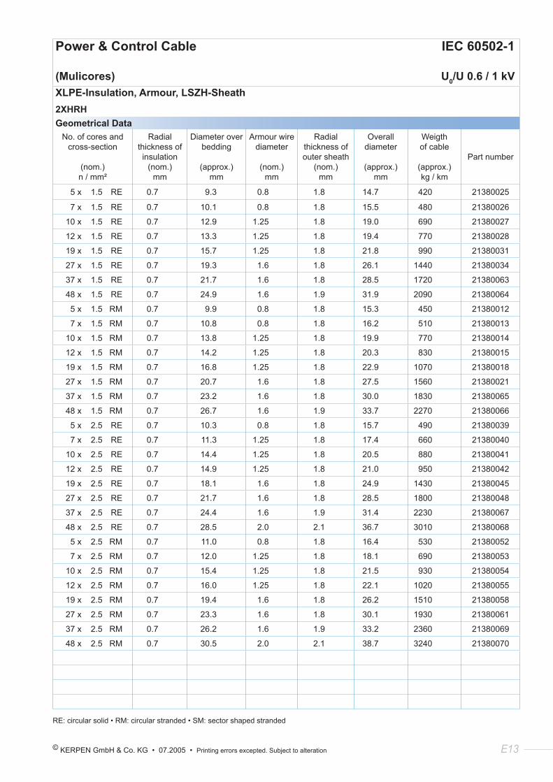
Power & Control Cable IEC 60502-1
(Mulicores) U0/U 0.6 / 1 kVXLPE-Insulation, Armour, LSZH-Sheath2XHRHGeometrical Data
No. of cores and cross-section
(nom.) n / mm²
Radial thickness of insulation
(nom.) mm
Diameter over bedding
(approx.) mm
Armour wire diameter
(nom.)
mm
Radial thickness of outer sheath
(nom.) mm
Overall diameter
(approx.)
mm
Weigth of cable
(approx.) kg / km
Part number
5 x 1.5 RE 0.7 9.3 0.8 1.8 14.7 420 21380025
7 x 1.5 RE 0.7 10.1 0.8 1.8 15.5 480 21380026
10 x 1.5 RE 0.7 12.9 1.25 1.8 19.0 690 21380027
12 x 1.5 RE 0.7 13.3 1.25 1.8 19.4 770 21380028
19 x 1.5 RE 0.7 15.7 1.25 1.8 21.8 990 21380031
27 x 1.5 RE 0.7 19.3 1.6 1.8 26.1 1440 21380034
37 x 1.5 RE 0.7 21.7 1.6 1.8 28.5 1720 21380063
48 x 1.5 RE 0.7 24.9 1.6 1.9 31.9 2090 21380064
5 x 1.5 RM 0.7 9.9 0.8 1.8 15.3 450 21380012
7 x 1.5 RM 0.7 10.8 0.8 1.8 16.2 510 21380013
10 x 1.5 RM 0.7 13.8 1.25 1.8 19.9 770 21380014
12 x 1.5 RM 0.7 14.2 1.25 1.8 20.3 830 21380015
19 x 1.5 RM 0.7 16.8 1.25 1.8 22.9 1070 21380018
27 x 1.5 RM 0.7 20.7 1.6 1.8 27.5 1560 21380021
37 x 1.5 RM 0.7 23.2 1.6 1.8 30.0 1830 21380065
48 x 1.5 RM 0.7 26.7 1.6 1.9 33.7 2270 21380066
5 x 2.5 RE 0.7 10.3 0.8 1.8 15.7 490 21380039
7 x 2.5 RE 0.7 11.3 1.25 1.8 17.4 660 21380040
10 x 2.5 RE 0.7 14.4 1.25 1.8 20.5 880 21380041
12 x 2.5 RE 0.7 14.9 1.25 1.8 21.0 950 21380042
19 x 2.5 RE 0.7 18.1 1.6 1.8 24.9 1430 21380045
27 x 2.5 RE 0.7 21.7 1.6 1.8 28.5 1800 21380048
37 x 2.5 RE 0.7 24.4 1.6 1.9 31.4 2230 21380067
48 x 2.5 RE 0.7 28.5 2.0 2.1 36.7 3010 21380068
5 x 2.5 RM 0.7 11.0 0.8 1.8 16.4 530 21380052
7 x 2.5 RM 0.7 12.0 1.25 1.8 18.1 690 21380053
10 x 2.5 RM 0.7 15.4 1.25 1.8 21.5 930 21380054
12 x 2.5 RM 0.7 16.0 1.25 1.8 22.1 1020 21380055
19 x 2.5 RM 0.7 19.4 1.6 1.8 26.2 1510 21380058
27 x 2.5 RM 0.7 23.3 1.6 1.8 30.1 1930 21380061
37 x 2.5 RM 0.7 26.2 1.6 1.9 33.2 2360 21380069
48 x 2.5 RM 0.7 30.5 2.0 2.1 38.7 3240 21380070
RE: circular solid • RM: circular stranded • SM: sector shaped stranded

E14 KERPEN GmbH & Co. KG • 07.2005 • Printing errors excepted. Subject to alteration
© KERPEN GmbH & Co. KG • 07.2005 • Printing errors excepted. Subject to alteration F1
Section 4:
Zero Halogen & Fire Resistant
Low Voltage Cables (90 °C)
U0 /U 0.6 / 1 kV
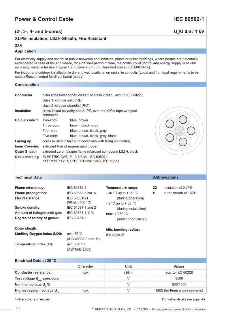
F2 KERPEN GmbH & Co. KG • 07.2005 • Printing errors excepted. Subject to alteration
Power & Control Cable IEC 60502-1
(2-, 3-, 4- and 5-cores) U0/U 0.6 / 1 kVXLPE-Insulation, LSZH-Sheath, Fire Resistant2XHApplication
For electricity supply and control in public networks and industrial plants or public buildings, where people are potentially endangered in case of fire and where, for a defined period of time, the continuity of control and energy supply is of vital necessity; suitable for use in zone 1 and zone 2 group ΙΙ classified areas (IEC 60079-14).For indoor and outdoor installation in dry and wet locations, on racks, in conduits (Local and / or legal requirements to be noted) Reccomended for direct burial (partly).
Construction
Conductor plain annealed copper, class 1 or class 2 resp., acc. to IEC 60228, class 1: circular solid (RE) class 2: circular stranded (RM)Insulation cross-linked polyethylene XLPE, over the MICA-tape wrapped conductorColour code 1) Two-core: blue, brown Three-core: brown, black, grey Four-core: blue, brown, black, grey Five-core: blue, brown, black, grey, blackLaying up cores twisted in layers (if necessary with filling element(s))Inner Covering extruded filler of regenerated rubberOuter Sheath extruded zero halogen flame retardant compound LSZH, blackCable marking ELECTRIC CABLE 0.6/1 kV IEC 60502-1 KERPEN, YEAR, LENGTH MARKING, IEC 60331
Technical Data Abbreviations
Flame retardancy:Flame propagation:Fire resistance:
Smoke density:Amount of halogen acid gas:Degree of acidity of gases:
Outer sheath:Limiting Oxygen Index (LOI):
Temperature Index (TI):
IEC 60332-1IEC 60332-3 cat. AIEC 60331-21 (90 min/750 °C)IEC 61034-1 and 2IEC 60754-1; 0 %IEC 60754-2
min. 30 %(IEC 60332-3 ann. B)min. 250 °C(ASTM-D-2863)
Temperature range:- 30 °C up to + 90 °C (during operation)- 5 °C up to + 50 °C (during installation)max. + 250 °C (under short circuit)
Min. bending radius:8 x cable-∅
2X insulation of XLPEH outer sheath of LSZH
Electrical Data at 20 °CCharacter Unit Values
Conductor resistance max. Ω/km acc. to IEC 60228
Test voltage Urms core:core V 3500
Nominal voltage Uo /U V 600/1000
Highest system voltage Um max. V 1200 (for three phase systems)
1) other colours on request For further details see appendix
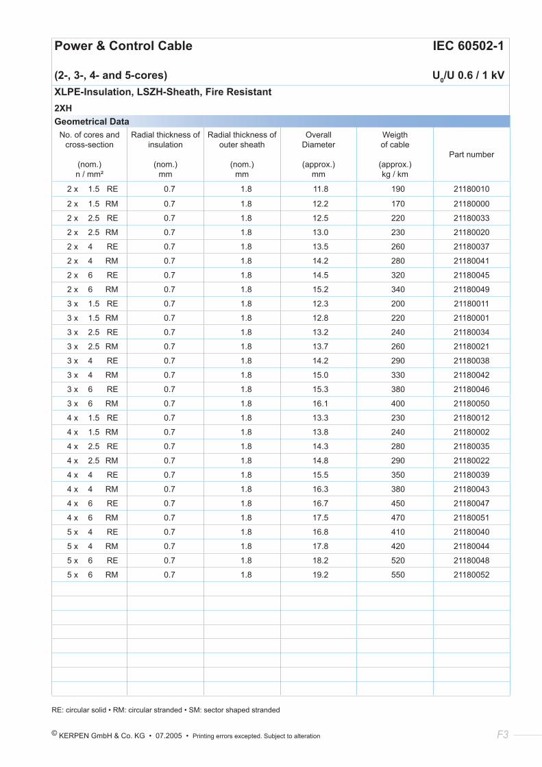
© KERPEN GmbH & Co. KG • 07.2005 • Printing errors excepted. Subject to alteration F3
Geometrical DataNo. of cores and
cross-section
(nom.) n / mm²
Radial thickness of insulation
(nom.) mm
Radial thickness of outer sheath
(nom.) mm
Overall Diameter
(approx.) mm
Weigth of cable
(approx.) kg / km
Part number
2 x 1.5 RE 0.7 1.8 11.8 190 21180010
2 x 1.5 RM 0.7 1.8 12.2 170 21180000
2 x 2.5 RE 0.7 1.8 12.5 220 21180033
2 x 2.5 RM 0.7 1.8 13.0 230 21180020
2 x 4 RE 0.7 1.8 13.5 260 21180037
2 x 4 RM 0.7 1.8 14.2 280 21180041
2 x 6 RE 0.7 1.8 14.5 320 21180045
2 x 6 RM 0.7 1.8 15.2 340 21180049
3 x 1.5 RE 0.7 1.8 12.3 200 21180011
3 x 1.5 RM 0.7 1.8 12.8 220 21180001
3 x 2.5 RE 0.7 1.8 13.2 240 21180034
3 x 2.5 RM 0.7 1.8 13.7 260 21180021
3 x 4 RE 0.7 1.8 14.2 290 21180038
3 x 4 RM 0.7 1.8 15.0 330 21180042
3 x 6 RE 0.7 1.8 15.3 380 21180046
3 x 6 RM 0.7 1.8 16.1 400 21180050
4 x 1.5 RE 0.7 1.8 13.3 230 21180012
4 x 1.5 RM 0.7 1.8 13.8 240 21180002
4 x 2.5 RE 0.7 1.8 14.3 280 21180035
4 x 2.5 RM 0.7 1.8 14.8 290 21180022
4 x 4 RE 0.7 1.8 15.5 350 21180039
4 x 4 RM 0.7 1.8 16.3 380 21180043
4 x 6 RE 0.7 1.8 16.7 450 21180047
4 x 6 RM 0.7 1.8 17.5 470 21180051
5 x 4 RE 0.7 1.8 16.8 410 21180040
5 x 4 RM 0.7 1.8 17.8 420 21180044
5 x 6 RE 0.7 1.8 18.2 520 21180048
5 x 6 RM 0.7 1.8 19.2 550 21180052
RE: circular solid • RM: circular stranded • SM: sector shaped stranded
Power & Control Cable IEC 60502-1
(2-, 3-, 4- and 5-cores) U0/U 0.6 / 1 kVXLPE-Insulation, LSZH-Sheath, Fire Resistant2XH
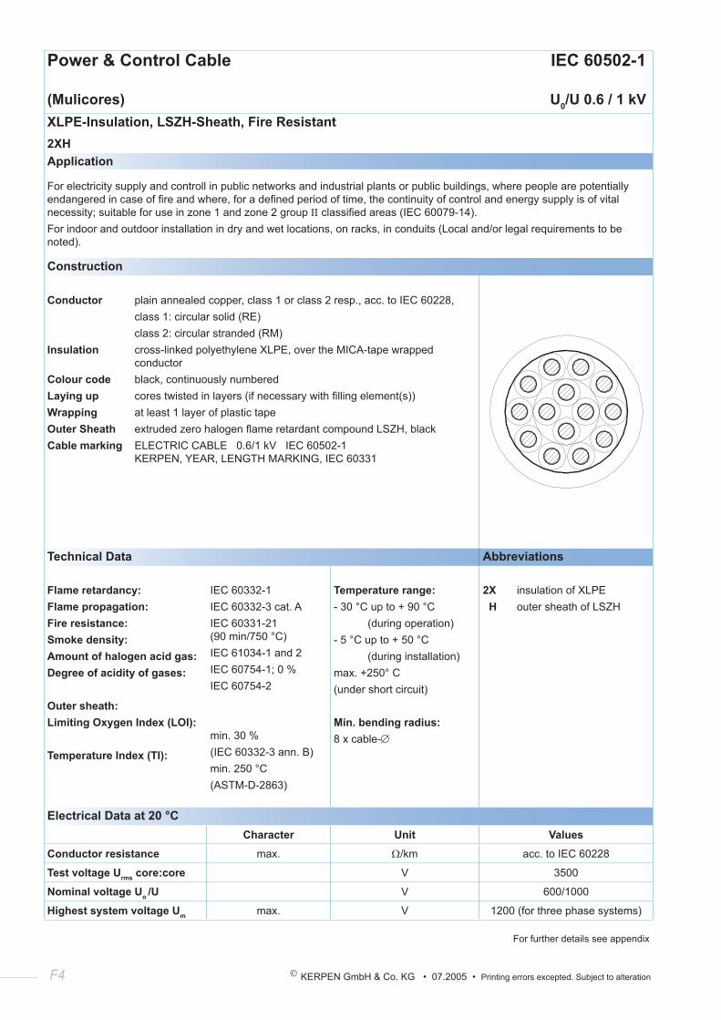
F4 KERPEN GmbH & Co. KG • 07.2005 • Printing errors excepted. Subject to alteration
Power & Control Cable IEC 60502-1
(Mulicores) U0/U 0.6 / 1 kVXLPE-Insulation, LSZH-Sheath, Fire Resistant2XHApplication
For electricity supply and controll in public networks and industrial plants or public buildings, where people are potentially endangered in case of fire and where, for a defined period of time, the continuity of control and energy supply is of vital necessity; suitable for use in zone 1 and zone 2 group ΙΙ classified areas (IEC 60079-14).For indoor and outdoor installation in dry and wet locations, on racks, in conduits (Local and/or legal requirements to be noted).
Construction
Conductor plain annealed copper, class 1 or class 2 resp., acc. to IEC 60228, class 1: circular solid (RE) class 2: circular stranded (RM)Insulation cross-linked polyethylene XLPE, over the MICA-tape wrapped conductorColour code black, continuously numberedLaying up cores twisted in layers (if necessary with filling element(s))Wrapping at least 1 layer of plastic tapeOuter Sheath extruded zero halogen flame retardant compound LSZH, blackCable marking ELECTRIC CABLE 0.6/1 kV IEC 60502-1 KERPEN, YEAR, LENGTH MARKING, IEC 60331
Technical Data Abbreviations
Flame retardancy:Flame propagation:Fire resistance:Smoke density:Amount of halogen acid gas:Degree of acidity of gases:
Outer sheath:Limiting Oxygen Index (LOI):
Temperature Index (TI):
IEC 60332-1IEC 60332-3 cat. AIEC 60331-21 (90 min/750 °C)IEC 61034-1 and 2IEC 60754-1; 0 %IEC 60754-2
min. 30 %(IEC 60332-3 ann. B)min. 250 °C(ASTM-D-2863)
Temperature range:- 30 °C up to + 90 °C (during operation)- 5 °C up to + 50 °C (during installation)max. +250° C(under short circuit)
Min. bending radius:8 x cable-∅
2X insulation of XLPE H outer sheath of LSZH
Electrical Data at 20 °CCharacter Unit Values
Conductor resistance max. Ω/km acc. to IEC 60228
Test voltage Urms core:core V 3500
Nominal voltage Uo /U V 600/1000
Highest system voltage Um max. V 1200 (for three phase systems)
For further details see appendix
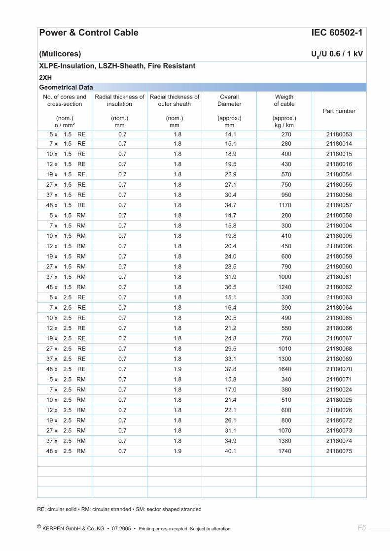
© KERPEN GmbH & Co. KG • 07.2005 • Printing errors excepted. Subject to alteration F5
Power & Control Cable IEC 60502-1
(Mulicores) U0/U 0.6 / 1 kVXLPE-Insulation, LSZH-Sheath, Fire Resistant2XHGeometrical Data
No. of cores and cross-section
(nom.) n / mm²
Radial thickness of insulation
(nom.) mm
Radial thickness of outer sheath
(nom.) mm
Overall Diameter
(approx.) mm
Weigth of cable
(approx.) kg / km
Part number
5 x 1.5 RE 0.7 1.8 14.1 270 21180053 7 x 1.5 RE 0.7 1.8 15.1 280 21180014
10 x 1.5 RE 0.7 1.8 18.9 400 21180015
12 x 1.5 RE 0.7 1.8 19.5 430 21180016
19 x 1.5 RE 0.7 1.8 22.9 570 21180054
27 x 1.5 RE 0.7 1.8 27.1 750 21180055
37 x 1.5 RE 0.7 1.8 30.4 950 21180056
48 x 1.5 RE 0.7 1.8 34.7 1170 21180057
5 x 1.5 RM 0.7 1.8 14.7 280 21180058
7 x 1.5 RM 0.7 1.8 15.8 300 21180004
10 x 1.5 RM 0.7 1.8 19.8 410 21180005
12 x 1.5 RM 0.7 1.8 20.4 450 21180006
19 x 1.5 RM 0.7 1.8 24.0 600 21180059
27 x 1.5 RM 0.7 1.8 28.5 790 21180060
37 x 1.5 RM 0.7 1.8 31.9 1000 21180061
48 x 1.5 RM 0.7 1.8 36.5 1240 21180062
5 x 2.5 RE 0.7 1.8 15.1 330 21180063
7 x 2.5 RE 0.7 1.8 16.4 390 21180064
10 x 2.5 RE 0.7 1.8 20.5 490 21180065
12 x 2.5 RE 0.7 1.8 21.2 550 21180066
19 x 2.5 RE 0.7 1.8 24.8 760 21180067
27 x 2.5 RE 0.7 1.8 29.5 1010 21180068
37 x 2.5 RE 0.7 1.8 33.1 1300 21180069
48 x 2.5 RE 0.7 1.9 37.8 1640 21180070
5 x 2.5 RM 0.7 1.8 15.8 340 21180071
7 x 2.5 RM 0.7 1.8 17.0 380 21180024
10 x 2.5 RM 0.7 1.8 21.4 510 21180025
12 x 2.5 RM 0.7 1.8 22.1 600 21180026
19 x 2.5 RM 0.7 1.8 26.1 800 21180072
27 x 2.5 RM 0.7 1.8 31.1 1070 21180073
37 x 2.5 RM 0.7 1.8 34.9 1380 21180074
48 x 2.5 RM 0.7 1.9 40.1 1740 21180075
RE: circular solid • RM: circular stranded • SM: sector shaped stranded
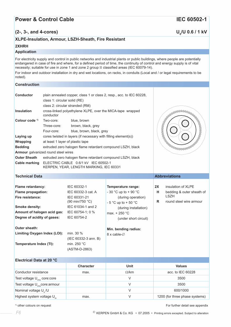
F6 KERPEN GmbH & Co. KG • 07.2005 • Printing errors excepted. Subject to alteration
Power & Control Cable IEC 60502-1
(2-, 3-, and 4-cores) U0/U 0.6 / 1 kVXLPE-Insulation, Armour, LSZH-Sheath, Fire Resistant2XHRHApplication
For electricity supply and control in public networks and industrial plants or public buildings, where people are potentially endangered in case of fire and where, for a defined period of time, the continuity of control and energy supply is of vital necessity; suitable for use in zone 1 and zone 2 group ΙΙ classified areas (IEC 60079-14).For indoor and outdoor installation in dry and wet locations, on racks, in conduits (Local and / or legal requirements to be noted).
Construction
Conductor plain annealed copper, class 1 or class 2, resp., acc. to IEC 60228, class 1: circular solid (RE) class 2: circular stranded (RM)Insulation cross-linked polyethylene XLPE, over the MICA-tape wrapped conductorColour code 1) Two-core: blue, brown Three-core: brown, black, grey Four-core: blue, brown, black, greyLaying up cores twisted in layers (if necessary with filling element(s))Wrapping at least 1 layer of plastic tapeBedding extruded zero halogen flame retardant compound LSZH, blackArmour galvanized round steel wiresOuter Sheath extruded zero halogen flame retardant compound LSZH, blackCable marking ELECTRIC CABLE 0.6/1 kV IEC 60502-1 KERPEN, YEAR, LENGTH MARKING, IEC 60331
Technical Data Abbreviations
Flame retardancy:Flame propagation:Fire resistance:
Smoke density:Amount of halogen acid gas:Degree of acidity of gases:
Outer sheath:Limiting Oxygen Index (LOI):
Temperature Index (TI):
IEC 60332-1IEC 60332-3 cat. AIEC 60331-21 (90 min/750 °C)IEC 61034-1 and 2IEC 60754-1; 0 %IEC 60754-2
min. 30 %(IEC 60332-3 ann. B)min. 250 °C(ASTM-D-2863)
Temperature range:- 30 °C up to + 90 °C (during operation)- 5 °C up to + 50 °C (during installation)max. + 250 °C (under short circuit)
Min. bending radius:8 x cable-∅
2X insulation of XLPE H bedding & outer sheath of LSZH R round steel wire armour
Electrical Data at 20 °CCharacter Unit Values
Conductor resistance max. Ω/km acc. to IEC 60228
Test voltage Urms core:core V 3500
Test voltage Urmscore:armour V 3500
Nominal voltage Uo /U V 600/1000
Highest system voltage Um max. V 1200 (for three phase systems)
1) other colours on request For further detail see appendix
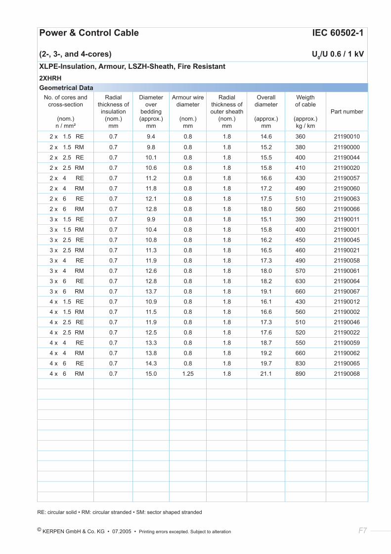
© KERPEN GmbH & Co. KG • 07.2005 • Printing errors excepted. Subject to alteration F7
Power & Control Cable IEC 60502-1
(2-, 3-, and 4-cores) U0/U 0.6 / 1 kVXLPE-Insulation, Armour, LSZH-Sheath, Fire Resistant2XHRHGeometrical Data
No. of cores and cross-section
(nom.) n / mm²
Radial thickness of insulation
(nom.) mm
Diameter over
bedding(approx.)
mm
Armour wire diameter
(nom.) mm
Radial thickness of outer sheath
(nom.) mm
Overall diameter
(approx.) mm
Weigth of cable
(approx.) kg / km
Part number
2 x 1.5 RE 0.7 9.4 0.8 1.8 14.6 360 21190010
2 x 1.5 RM 0.7 9.8 0.8 1.8 15.2 380 21190000
2 x 2.5 RE 0.7 10.1 0.8 1.8 15.5 400 21190044
2 x 2.5 RM 0.7 10.6 0.8 1.8 15.8 410 21190020
2 x 4 RE 0.7 11.2 0.8 1.8 16.6 430 21190057
2 x 4 RM 0.7 11.8 0.8 1.8 17.2 490 21190060
2 x 6 RE 0.7 12.1 0.8 1.8 17.5 510 21190063
2 x 6 RM 0.7 12.8 0.8 1.8 18.0 560 21190066
3 x 1.5 RE 0.7 9.9 0.8 1.8 15.1 390 21190011
3 x 1.5 RM 0.7 10.4 0.8 1.8 15.8 400 21190001
3 x 2.5 RE 0.7 10.8 0.8 1.8 16.2 450 21190045
3 x 2.5 RM 0.7 11.3 0.8 1.8 16.5 460 21190021
3 x 4 RE 0.7 11.9 0.8 1.8 17.3 490 21190058
3 x 4 RM 0.7 12.6 0.8 1.8 18.0 570 21190061
3 x 6 RE 0.7 12.8 0.8 1.8 18.2 630 21190064
3 x 6 RM 0.7 13.7 0.8 1.8 19.1 660 21190067
4 x 1.5 RE 0.7 10.9 0.8 1.8 16.1 430 21190012
4 x 1.5 RM 0.7 11.5 0.8 1.8 16.6 560 21190002
4 x 2.5 RE 0.7 11.9 0.8 1.8 17.3 510 21190046
4 x 2.5 RM 0.7 12.5 0.8 1.8 17.6 520 21190022
4 x 4 RE 0.7 13.3 0.8 1.8 18.7 550 21190059
4 x 4 RM 0.7 13.8 0.8 1.8 19.2 660 21190062
4 x 6 RE 0.7 14.3 0.8 1.8 19.7 830 21190065
4 x 6 RM 0.7 15.0 1.25 1.8 21.1 890 21190068
RE: circular solid • RM: circular stranded • SM: sector shaped stranded
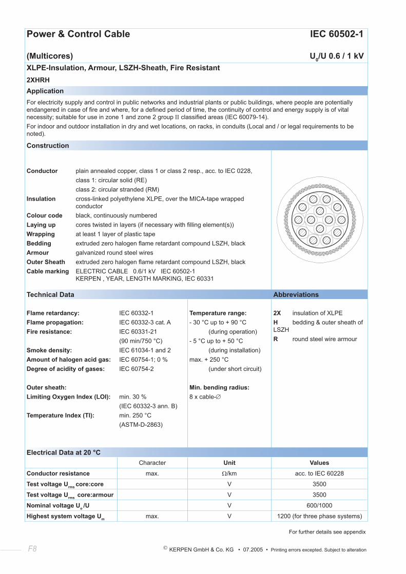
F8 KERPEN GmbH & Co. KG • 07.2005 • Printing errors excepted. Subject to alteration
Power & Control Cable IEC 60502-1
(Multicores) U0/U 0.6 / 1 kVXLPE-Insulation, Armour, LSZH-Sheath, Fire Resistant2XHRHApplicationFor electricity supply and control in public networks and industrial plants or public buildings, where people are potentially endangered in case of fire and where, for a defined period of time, the continuity of control and energy supply is of vital necessity; suitable for use in zone 1 and zone 2 group ΙΙ classified areas (IEC 60079-14).For indoor and outdoor installation in dry and wet locations, on racks, in conduits (Local and / or legal requirements to be noted).
Construction
Conductor plain annealed copper, class 1 or class 2 resp., acc. to IEC 0228, class 1: circular solid (RE) class 2: circular stranded (RM)Insulation cross-linked polyethylene XLPE, over the MICA-tape wrapped conductorColour code black, continuously numberedLaying up cores twisted in layers (if necessary with filling element(s))Wrapping at least 1 layer of plastic tapeBedding extruded zero halogen flame retardant compound LSZH, blackArmour galvanized round steel wiresOuter Sheath extruded zero halogen flame retardant compound LSZH, blackCable marking ELECTRIC CABLE 0.6/1 kV IEC 60502-1 KERPEN , YEAR, LENGTH MARKING, IEC 60331
Technical Data Abbreviations
Flame retardancy:Flame propagation:Fire resistance:
Smoke density:Amount of halogen acid gas:Degree of acidity of gases:
Outer sheath:Limiting Oxygen Index (LOI):
Temperature Index (TI):
IEC 60332-1IEC 60332-3 cat. AIEC 60331-21 (90 min/750 °C)IEC 61034-1 and 2IEC 60754-1; 0 %IEC 60754-2
min. 30 %(IEC 60332-3 ann. B)min. 250 °C(ASTM-D-2863)
Temperature range:- 30 °C up to + 90 °C (during operation)- 5 °C up to + 50 °C (during installation)max. + 250 °C (under short circuit)
Min. bending radius:8 x cable-∅
2X insulation of XLPEH bedding & outer sheath of LSZHR round steel wire armour
Electrical Data at 20 °CCharacter Unit Values
Conductor resistance max. Ω/km acc. to IEC 60228
Test voltage Urms core:core V 3500
Test voltage Urms core:armour V 3500
Nominal voltage Uo /U V 600/1000
Highest system voltage Um max. V 1200 (for three phase systems)
For further details see appendix
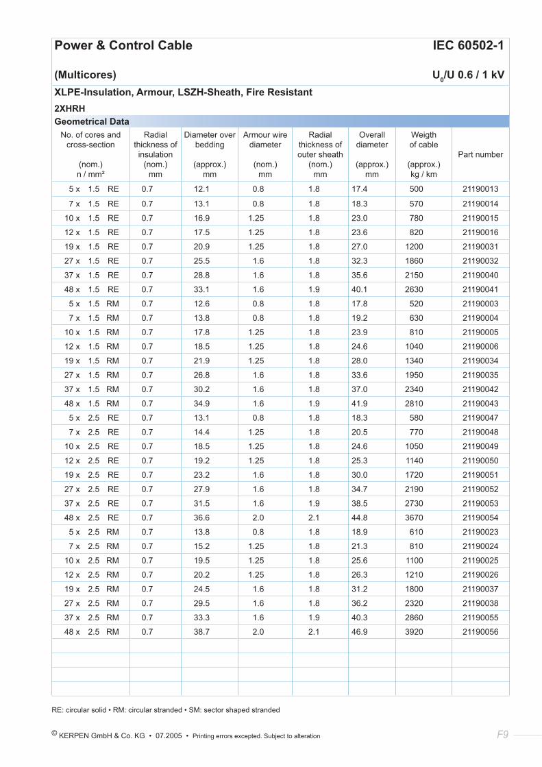
© KERPEN GmbH & Co. KG • 07.2005 • Printing errors excepted. Subject to alteration F9
Power & Control Cable IEC 60502-1
(Multicores) U0/U 0.6 / 1 kVXLPE-Insulation, Armour, LSZH-Sheath, Fire Resistant2XHRHGeometrical Data
No. of cores and cross-section
(nom.) n / mm²
Radial thickness of insulation
(nom.) mm
Diameter over bedding
(approx.) mm
Armour wire diameter
(nom.) mm
Radial thickness of outer sheath
(nom.) mm
Overall diameter
(approx.)
mm
Weigth of cable
(approx.) kg / km
Part number
5 x 1.5 RE 0.7 12.1 0.8 1.8 17.4 500 21190013
7 x 1.5 RE 0.7 13.1 0.8 1.8 18.3 570 21190014
10 x 1.5 RE 0.7 16.9 1.25 1.8 23.0 780 21190015
12 x 1.5 RE 0.7 17.5 1.25 1.8 23.6 820 21190016
19 x 1.5 RE 0.7 20.9 1.25 1.8 27.0 1200 21190031
27 x 1.5 RE 0.7 25.5 1.6 1.8 32.3 1860 21190032
37 x 1.5 RE 0.7 28.8 1.6 1.8 35.6 2150 21190040
48 x 1.5 RE 0.7 33.1 1.6 1.9 40.1 2630 21190041
5 x 1.5 RM 0.7 12.6 0.8 1.8 17.8 520 21190003
7 x 1.5 RM 0.7 13.8 0.8 1.8 19.2 630 21190004
10 x 1.5 RM 0.7 17.8 1.25 1.8 23.9 810 21190005
12 x 1.5 RM 0.7 18.5 1.25 1.8 24.6 1040 21190006
19 x 1.5 RM 0.7 21.9 1.25 1.8 28.0 1340 21190034
27 x 1.5 RM 0.7 26.8 1.6 1.8 33.6 1950 21190035
37 x 1.5 RM 0.7 30.2 1.6 1.8 37.0 2340 21190042
48 x 1.5 RM 0.7 34.9 1.6 1.9 41.9 2810 21190043
5 x 2.5 RE 0.7 13.1 0.8 1.8 18.3 580 21190047
7 x 2.5 RE 0.7 14.4 1.25 1.8 20.5 770 21190048
10 x 2.5 RE 0.7 18.5 1.25 1.8 24.6 1050 21190049
12 x 2.5 RE 0.7 19.2 1.25 1.8 25.3 1140 21190050
19 x 2.5 RE 0.7 23.2 1.6 1.8 30.0 1720 21190051
27 x 2.5 RE 0.7 27.9 1.6 1.8 34.7 2190 21190052
37 x 2.5 RE 0.7 31.5 1.6 1.9 38.5 2730 21190053
48 x 2.5 RE 0.7 36.6 2.0 2.1 44.8 3670 21190054
5 x 2.5 RM 0.7 13.8 0.8 1.8 18.9 610 21190023
7 x 2.5 RM 0.7 15.2 1.25 1.8 21.3 810 21190024
10 x 2.5 RM 0.7 19.5 1.25 1.8 25.6 1100 21190025
12 x 2.5 RM 0.7 20.2 1.25 1.8 26.3 1210 21190026
19 x 2.5 RM 0.7 24.5 1.6 1.8 31.2 1800 21190037
27 x 2.5 RM 0.7 29.5 1.6 1.8 36.2 2320 21190038
37 x 2.5 RM 0.7 33.3 1.6 1.9 40.3 2860 21190055
48 x 2.5 RM 0.7 38.7 2.0 2.1 46.9 3920 21190056
RE: circular solid • RM: circular stranded • SM: sector shaped stranded

F10 KERPEN GmbH & Co. KG • 07.2005 • Printing errors excepted. Subject to alteration
© KERPEN GmbH & Co. KG • 07.2005 • Printing errors excepted. Subject to alteration G1
Section 5:
Additional Cable Variations
Low Voltage Cables
U0 /U 0.6 / 1 kV

G2 KERPEN GmbH & Co. KG • 07.2005 • Printing errors excepted. Subject to alteration
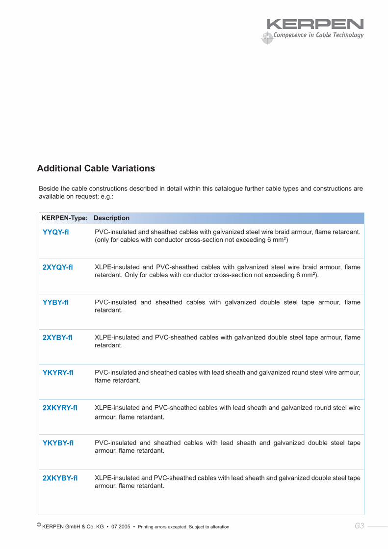
© KERPEN GmbH & Co. KG • 07.2005 • Printing errors excepted. Subject to alteration G3
Additional Cable Variations
Beside the cable constructions described in detail within this catalogue further cable types and constructions are available on request; e.g.:
KERPEN-Type: Description
YYQY-fl PVC-insulated and sheathed cables with galvanized steel wire braid armour, flame retardant. (only for cables with conductor cross-section not exceeding 6 mm²)
2XYQY-fl XLPE-insulated and PVC-sheathed cables with galvanized steel wire braid armour, flame retardant. Only for cables with conductor cross-section not exceeding 6 mm²).
YYBY-fl PVC-insulated and sheathed cables with galvanized double steel tape armour, flame retardant.
2XYBY-fl XLPE-insulated and PVC-sheathed cables with galvanized double steel tape armour, flame retardant.
YKYRY-fl PVC-insulated and sheathed cables with lead sheath and galvanized round steel wire armour, flame retardant.
2XKYRY-fl XLPE-insulated and PVC-sheathed cables with lead sheath and galvanized round steel wire armour, flame retardant.
YKYBY-fl PVC-insulated and sheathed cables with lead sheath and galvanized double steel tape armour, flame retardant.
2XKYBY-fl XLPE-insulated and PVC-sheathed cables with lead sheath and galvanized double steel tape armour, flame retardant.

G4 KERPEN GmbH & Co. KG • 07.2005 • Printing errors excepted. Subject to alteration
© KERPEN GmbH & Co. KG • 07.2005 • Printing errors excepted. Subject to alteration H1
Appendix:
I Additional Electrical Data
II Tests on Power and Control Cables
III General Information
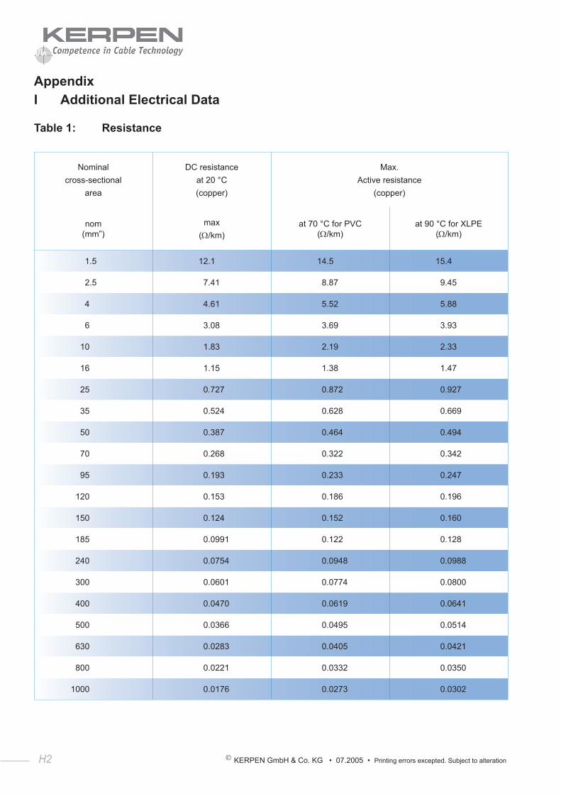
H2 KERPEN GmbH & Co. KG • 07.2005 • Printing errors excepted. Subject to alteration
H2
AppendixI Additional Electrical Data
Table 1: Resistance
Nominalcross-sectional
area
DC resistanceat 20 °C(copper)
Max.Active resistance
(copper)
nom (mm”)
max(Ω/km)
at 70 °C for PVC (Ω/km)
at 90 °C for XLPE (Ω/km)
1.5 12.1 14.5 15.4
2.5 7.41 8.87 9.45
4 4.61 5.52 5.88
6 3.08 3.69 3.93
10 1.83 2.19 2.33
16 1.15 1.38 1.47
25 0.727 0.872 0.927
35 0.524 0.628 0.669
50 0.387 0.464 0.494
70 0.268 0.322 0.342
95 0.193 0.233 0.247
120 0.153 0.186 0.196
150 0.124 0.152 0.160
185 0.0991 0.122 0.128
240 0.0754 0.0948 0.0988
300 0.0601 0.0774 0.0800
400 0.0470 0.0619 0.0641
500 0.0366 0.0495 0.0514
630 0.0283 0.0405 0.0421
800 0.0221 0.0332 0.0350
1000 0.0176 0.0273 0.0302
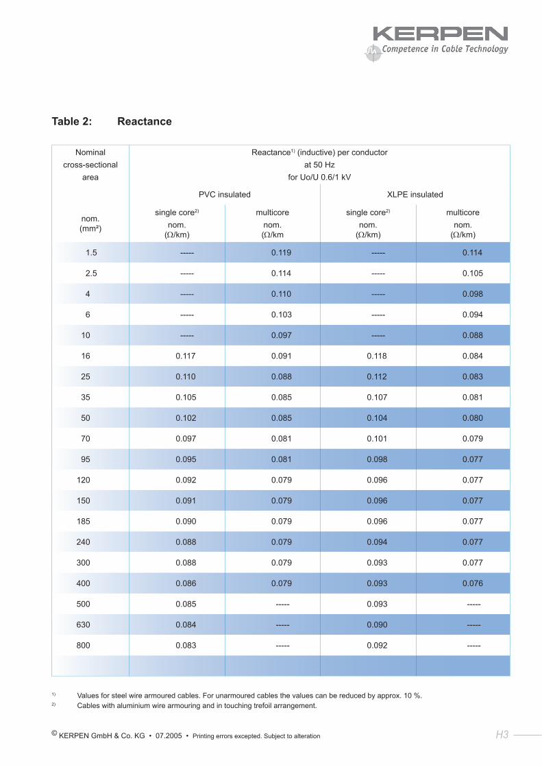
© KERPEN GmbH & Co. KG • 07.2005 • Printing errors excepted. Subject to alteration H3
Table 2: Reactance
Nominalcross-sectional
area
Reactance1) (inductive) per conductorat 50 Hz
for Uo/U 0.6/1 kV
PVC insulated XLPE insulated
nom. (mm²)
single core2)
nom. (Ω/km)
multicorenom. (Ω/km
single core2)
nom. (Ω/km)
multicorenom.
(Ω/km)
1.5 ----- 0.119 ----- 0.114
2.5 ----- 0.114 ----- 0.105
4 ----- 0.110 ----- 0.098
6 ----- 0.103 ----- 0.094
10 ----- 0.097 ----- 0.088
16 0.117 0.091 0.118 0.084
25 0.110 0.088 0.112 0.083
35 0.105 0.085 0.107 0.081
50 0.102 0.085 0.104 0.080
70 0.097 0.081 0.101 0.079
95 0.095 0.081 0.098 0.077
120 0.092 0.079 0.096 0.077
150 0.091 0.079 0.096 0.077
185 0.090 0.079 0.096 0.077
240 0.088 0.079 0.094 0.077
300 0.088 0.079 0.093 0.077
400 0.086 0.079 0.093 0.076
500 0.085 ----- 0.093 -----
630 0.084 ----- 0.090 -----
800 0.083 ----- 0.092 -----
1) Values for steel wire armoured cables. For unarmoured cables the values can be reduced by approx. 10 %.2) Cables with aluminium wire armouring and in touching trefoil arrangement.
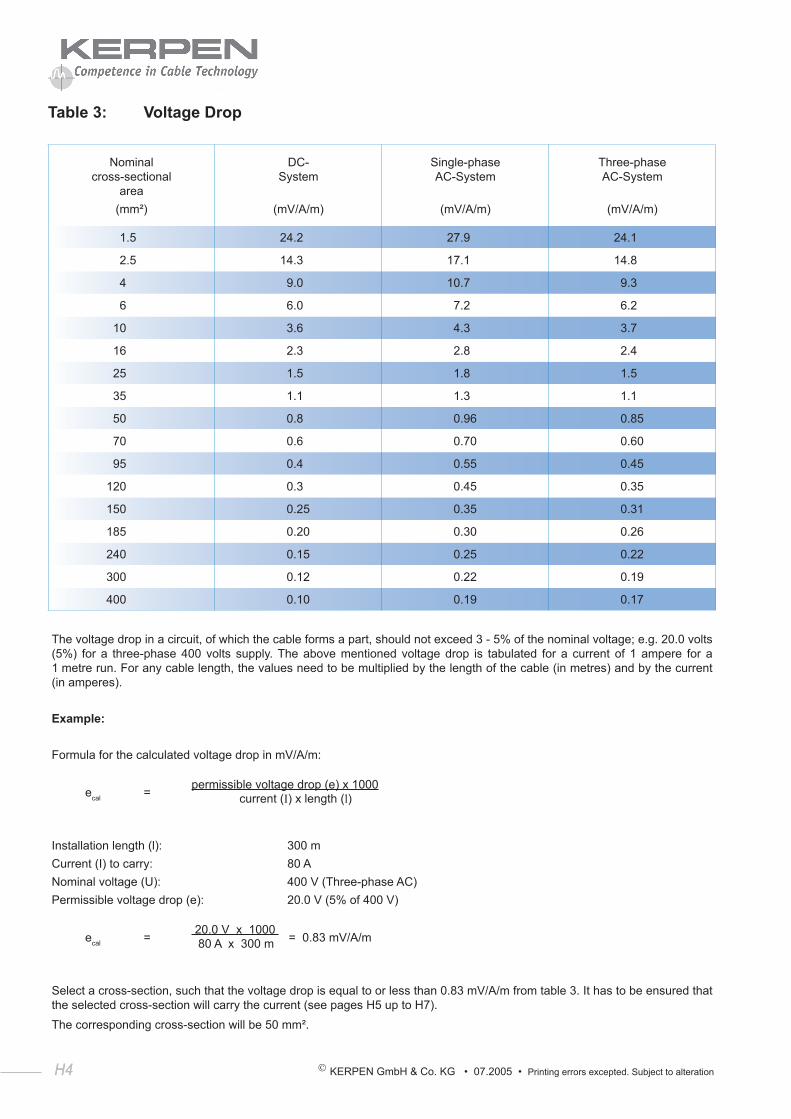
H4 KERPEN GmbH & Co. KG • 07.2005 • Printing errors excepted. Subject to alteration
H4
Table 3: Voltage Drop
Nominal cross-sectional
area(mm²)
DC- System
(mV/A/m)
Single-phase AC-System
(mV/A/m)
Three-phase AC-System
(mV/A/m)
1.5 24.2 27.9 24.1
2.5 14.3 17.1 14.8
4 9.0 10.7 9.3
6 6.0 7.2 6.2
10 3.6 4.3 3.7
16 2.3 2.8 2.4
25 1.5 1.8 1.5
35 1.1 1.3 1.1
50 0.8 0.96 0.85
70 0.6 0.70 0.60
95 0.4 0.55 0.45
120 0.3 0.45 0.35
150 0.25 0.35 0.31
185 0.20 0.30 0.26
240 0.15 0.25 0.22
300 0.12 0.22 0.19
400 0.10 0.19 0.17
The voltage drop in a circuit, of which the cable forms a part, should not exceed 3 - 5% of the nominal voltage; e.g. 20.0 volts (5%) for a three-phase 400 volts supply. The above mentioned voltage drop is tabulated for a current of 1 ampere for a 1 metre run. For any cable length, the values need to be multiplied by the length of the cable (in metres) and by the current (in amperes).
Example:
Formula for the calculated voltage drop in mV/A/m:
ecal = permissible voltage drop (e) x 1000
current (I) x length (l)
Installation length (l): 300 mCurrent (I) to carry: 80 ANominal voltage (U): 400 V (Three-phase AC)Permissible voltage drop (e): 20.0 V (5% of 400 V)
ecal = 20.0 V x 1000 = 0.83 mV/A/m
80 A x 300 m
Select a cross-section, such that the voltage drop is equal to or less than 0.83 mV/A/m from table 3. It has to be ensured that the selected cross-section will carry the current (see pages H5 up to H7).The corresponding cross-section will be 50 mm².
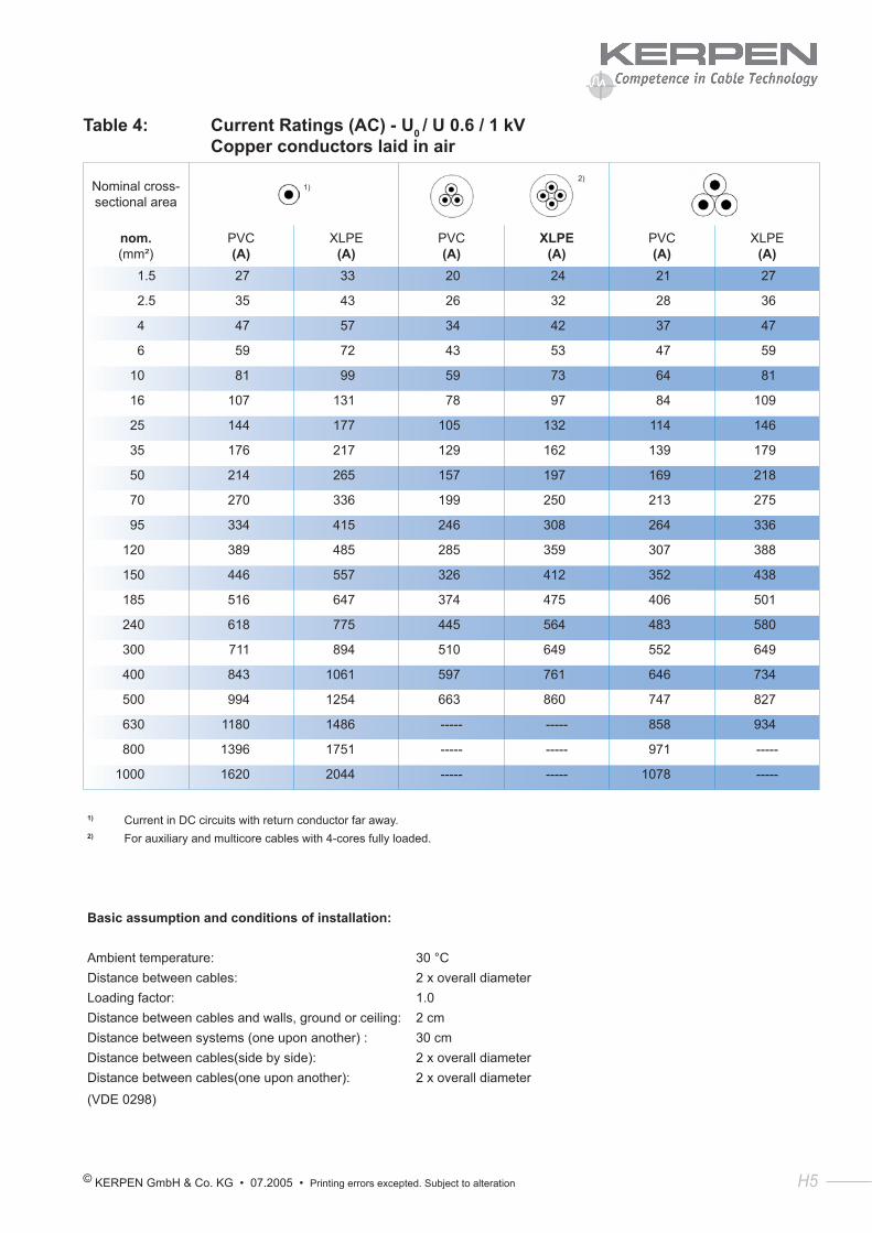
© KERPEN GmbH & Co. KG • 07.2005 • Printing errors excepted. Subject to alteration H5
Table 4: Current Ratings (AC) - U0 / U 0.6 / 1 kV Copper conductors laid in air
Nominal cross-sectional area
1)
2)
nom. (mm²)
PVC (A)
XLPE (A)
PVC (A)
XLPE (A)
PVC (A)
XLPE (A)
1.5 27 33 20 24 21 27
2.5 35 43 26 32 28 36
4 47 57 34 42 37 47
6 59 72 43 53 47 59
10 81 99 59 73 64 81
16 107 131 78 97 84 109
25 144 177 105 132 114 146
35 176 217 129 162 139 179
50 214 265 157 197 169 218
70 270 336 199 250 213 275
95 334 415 246 308 264 336
120 389 485 285 359 307 388
150 446 557 326 412 352 438
185 516 647 374 475 406 501
240 618 775 445 564 483 580
300 711 894 510 649 552 649
400 843 1061 597 761 646 734
500 994 1254 663 860 747 827
630 1180 1486 ----- ----- 858 934
800 1396 1751 ----- ----- 971 -----
1000 1620 2044 ----- ----- 1078 -----
1) Current in DC circuits with return conductor far away.2) For auxiliary and multicore cables with 4-cores fully loaded.
Basic assumption and conditions of installation:
Ambient temperature: 30 °CDistance between cables: 2 x overall diameterLoading factor: 1.0Distance between cables and walls, ground or ceiling: 2 cmDistance between systems (one upon another) : 30 cmDistance between cables(side by side): 2 x overall diameterDistance between cables(one upon another): 2 x overall diameter(VDE 0298)
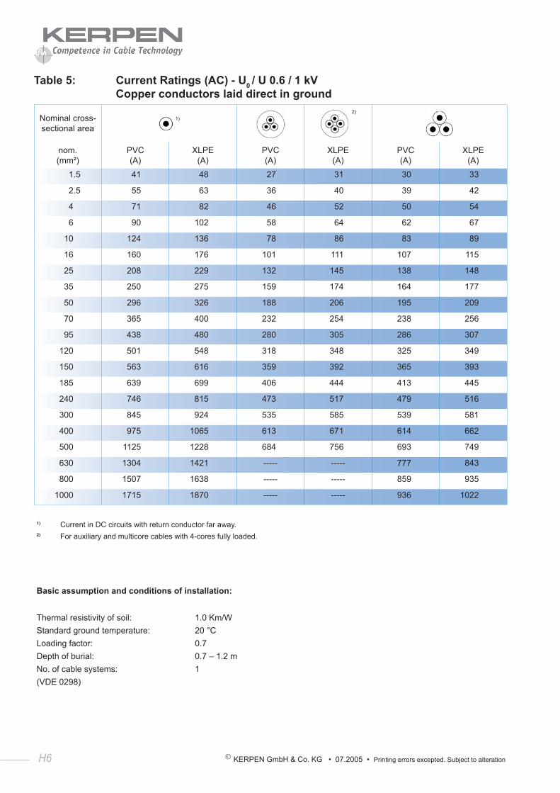
H6 KERPEN GmbH & Co. KG • 07.2005 • Printing errors excepted. Subject to alteration
H6
Table 5: Current Ratings (AC) - U0 / U 0.6 / 1 kV Copper conductors laid direct in ground
Nominal cross-sectional area
1)
2)
nom. (mm²)
PVC (A)
XLPE (A)
PVC (A)
XLPE (A)
PVC (A)
XLPE (A)
1.5 41 48 27 31 30 33
2.5 55 63 36 40 39 42
4 71 82 46 52 50 54
6 90 102 58 64 62 67
10 124 136 78 86 83 89
16 160 176 101 111 107 115
25 208 229 132 145 138 148
35 250 275 159 174 164 177
50 296 326 188 206 195 209
70 365 400 232 254 238 256
95 438 480 280 305 286 307
120 501 548 318 348 325 349
150 563 616 359 392 365 393
185 639 699 406 444 413 445
240 746 815 473 517 479 516
300 845 924 535 585 539 581
400 975 1065 613 671 614 662
500 1125 1228 684 756 693 749
630 1304 1421 ----- ----- 777 843
800 1507 1638 ----- ----- 859 935
1000 1715 1870 ----- ----- 936 1022
1) Current in DC circuits with return conductor far away.2) For auxiliary and multicore cables with 4-cores fully loaded.
Basic assumption and conditions of installation:
Thermal resistivity of soil: 1.0 Km/WStandard ground temperature: 20 °CLoading factor: 0.7Depth of burial: 0.7 – 1.2 mNo. of cable systems: 1(VDE 0298)
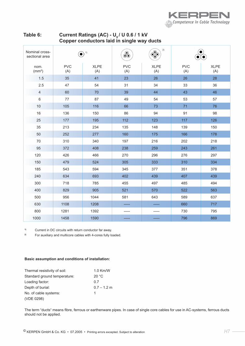
© KERPEN GmbH & Co. KG • 07.2005 • Printing errors excepted. Subject to alteration H7
Table 6: Current Ratings (AC) - U0 / U 0.6 / 1 kV Copper conductors laid in single way ducts
Nominal cross-sectional area
1)
2)
nom. (mm²)
PVC (A)
XLPE (A)
PVC (A)
XLPE (A)
PVC (A)
XLPE (A)
1.5 35 41 23 26 26 28
2.5 47 54 31 34 33 36
4 60 70 39 44 43 46
6 77 87 49 54 53 57
10 105 116 66 73 71 76
16 136 150 86 94 91 98
25 177 195 112 123 117 126
35 213 234 135 148 139 150
50 252 277 160 175 166 178
70 310 340 197 216 202 218
95 372 408 238 259 243 261
120 426 466 270 296 276 297
150 479 524 305 333 310 334
185 543 594 345 377 351 378
240 634 693 402 439 407 439
300 718 785 455 497 485 494
400 829 905 521 570 522 563
500 956 1044 581 643 589 637
630 1108 1208 ----- ----- 660 717
800 1281 1392 ----- ----- 730 795
1000 1458 1590 ----- ----- 796 869
1) Current in DC circuits with return conductor far away.2) For auxiliary and multicore cables with 4-cores fully loaded.
Basic assumption and conditions of installation:
Thermal resistivity of soil: 1.0 Km/WStandard ground temperature: 20 °CLoading factor: 0.7Depth of burial: 0.7 – 1.2 mNo. of cable systems: 1(VDE 0298)
The term “ducts“ means fibre, ferrous or earthenware pipes. In case of single core cables for use in AC-systems, ferrous ducts should not be applied.
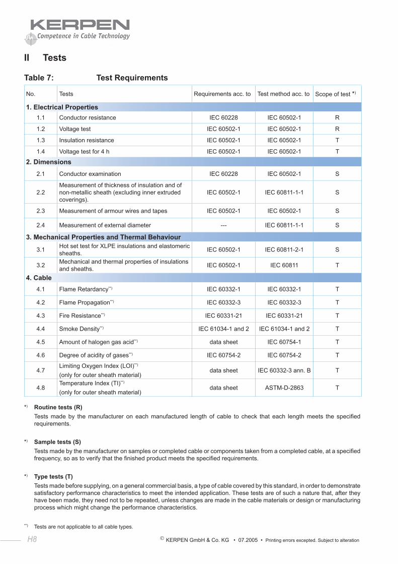
H8 KERPEN GmbH & Co. KG • 07.2005 • Printing errors excepted. Subject to alteration
H8
II Tests
Table 7: Test Requirements
No. Tests Requirements acc. to Test method acc. to Scope of test *)
1. Electrical Properties1.1 Conductor resistance IEC 60228 IEC 60502-1 R
1.2 Voltage test IEC 60502-1 IEC 60502-1 R
1.3 Insulation resistance IEC 60502-1 IEC 60502-1 T
1.4 Voltage test for 4 h IEC 60502-1 IEC 60502-1 T
2. Dimensions
2.1 Conductor examination IEC 60228 IEC 60502-1 S
2.2Measurement of thickness of insulation and of non-metallic sheath (excluding inner extruded coverings).
IEC 60502-1 IEC 60811-1-1 S
2.3 Measurement of armour wires and tapes IEC 60502-1 IEC 60502-1 S
2.4 Measurement of external diameter --- IEC 60811-1-1 S
3. Mechanical Properties and Thermal Behaviour
3.1 Hot set test for XLPE insulations and elastomeric sheaths. IEC 60502-1 IEC 60811-2-1 S
3.2 Mechanical and thermal properties of insulations and sheaths. IEC 60502-1 IEC 60811 T
4. Cable4.1 Flame Retardancy**) IEC 60332-1 IEC 60332-1 T
4.2 Flame Propagation**) IEC 60332-3 IEC 60332-3 T
4.3 Fire Resistance**) IEC 60331-21 IEC 60331-21 T
4.4 Smoke Density**) IEC 61034-1 and 2 IEC 61034-1 and 2 T
4.5 Amount of halogen gas acid**) data sheet IEC 60754-1 T
4.6 Degree of acidity of gases**) IEC 60754-2 IEC 60754-2 T
4.7Limiting Oxygen Index (LOI)**)
(only for outer sheath material)data sheet IEC 60332-3 ann. B T
4.8Temperature Index (TI)**)
(only for outer sheath material)data sheet ASTM-D-2863 T
*) Routine tests (R) Tests made by the manufacturer on each manufactured length of cable to check that each length meets the specified
requirements.
*) Sample tests (S) Tests made by the manufacturer on samples or completed cable or components taken from a completed cable, at a specified
frequency, so as to verify that the finished product meets the specified requirements.
*) Type tests (T) Tests made before supplying, on a general commercial basis, a type of cable covered by this standard, in order to demonstrate
satisfactory performance characteristics to meet the intended application. These tests are of such a nature that, after they have been made, they need not to be repeated, unless changes are made in the cable materials or design or manufacturing process which might change the performance characteristics.
**) Tests are not applicable to all cable types.
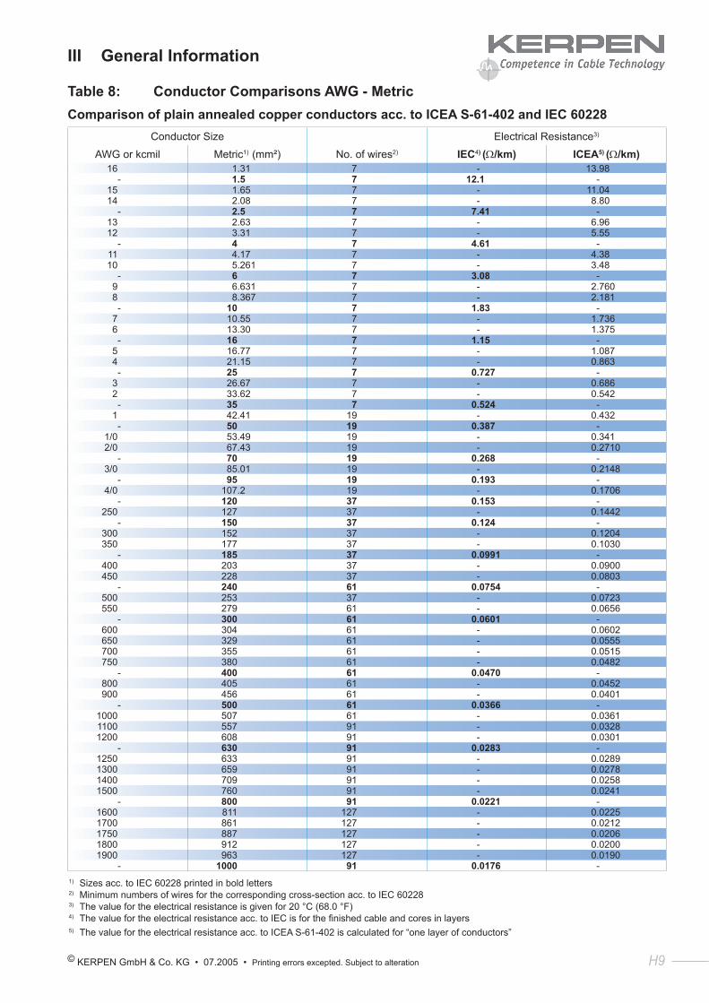
© KERPEN GmbH & Co. KG • 07.2005 • Printing errors excepted. Subject to alteration H9
III General Information
Table 8: Conductor Comparisons AWG - MetricComparison of plain annealed copper conductors acc. to ICEA S-61-402 and IEC 60228
Conductor Size Electrical Resistance3)
AWG or kcmil Metric1) (mm²) No. of wires2) IEC4) (Ω/km) ICEA5) (Ω/km)16 1.31 7 - 13.98
- 1.5 7 12.1 -15 1.65 7 - 11.0414 2.08 7 - 8.80
- 2.5 7 7.41 -13 2.63 7 - 6.9612 3.31 7 - 5.55
- 4 7 4.61 -11 4.17 7 - 4.3810 5.261 7 - 3.48
- 6 7 3.08 -9 6.631 7 - 2.7608 8.367 7 - 2.181
- 10 7 1.83 -7 10.55 7 - 1.7366 13.30 7 - 1.375
- 16 7 1.15 -5 16.77 7 - 1.0874 21.15 7 - 0.863
- 25 7 0.727 -3 26.67 7 - 0.6862 33.62 7 - 0.542
- 35 7 0.524 -1 42.41 19 - 0.432
- 50 19 0.387 -1/0 53.49 19 - 0.3412/0 67.43 19 - 0.2710
- 70 19 0.268 -3/0 85.01 19 - 0.2148
- 95 19 0.193 -4/0 107.2 19 - 0.1706
- 120 37 0.153 -250 127 37 - 0.1442
- 150 37 0.124 -300 152 37 - 0.1204350 177 37 - 0.1030
- 185 37 0.0991 -400 203 37 - 0.0900450 228 37 - 0.0803
- 240 61 0.0754 -500 253 37 - 0.0723550 279 61 - 0.0656
- 300 61 0.0601 -600 304 61 - 0.0602650 329 61 - 0.0555700 355 61 - 0.0515750 380 61 - 0.0482
- 400 61 0.0470 -800 405 61 - 0.0452900 456 61 - 0.0401
- 500 61 0.0366 -1000 507 61 - 0.03611100 557 91 - 0.03281200 608 91 - 0.0301
- 630 91 0.0283 -1250 633 91 - 0.02891300 659 91 - 0.02781400 709 91 - 0.02581500 760 91 - 0.0241
- 800 91 0.0221 -1600 811 127 - 0.02251700 861 127 - 0.02121750 887 127 - 0.02061800 912 127 - 0.02001900 963 127 - 0.0190
- 1000 91 0.0176 -1) Sizes acc. to IEC 60228 printed in bold letters2) Minimum numbers of wires for the corresponding cross-section acc. to IEC 602283) The value for the electrical resistance is given for 20 °C (68.0 °F)4) The value for the electrical resistance acc. to IEC is for the finished cable and cores in layers5) The value for the electrical resistance acc. to ICEA S-61-402 is calculated for “one layer of conductors”

H10 KERPEN GmbH & Co. KG • 07.2005 • Printing errors excepted. Subject to alteration
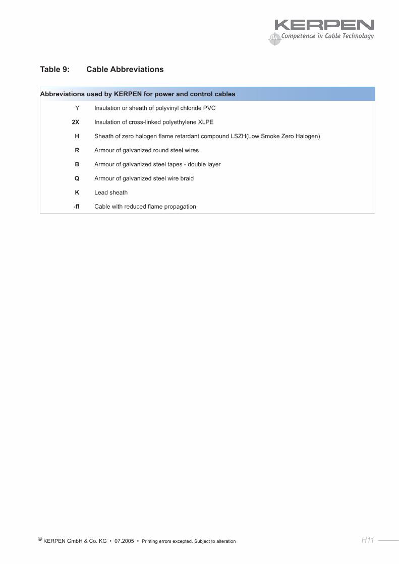
© KERPEN GmbH & Co. KG • 07.2005 • Printing errors excepted. Subject to alteration H11
Table 9: Cable Abbreviations
Abbreviations used by KERPEN for power and control cables
Y Insulation or sheath of polyvinyl chloride PVC
2X Insulation of cross-linked polyethylene XLPE
H Sheath of zero halogen flame retardant compound LSZH(Low Smoke Zero Halogen)
R Armour of galvanized round steel wires
B Armour of galvanized steel tapes - double layer
Q Armour of galvanized steel wire braid
K Lead sheath
-fl Cable with reduced flame propagation