Embed Size (px)
Citation preview
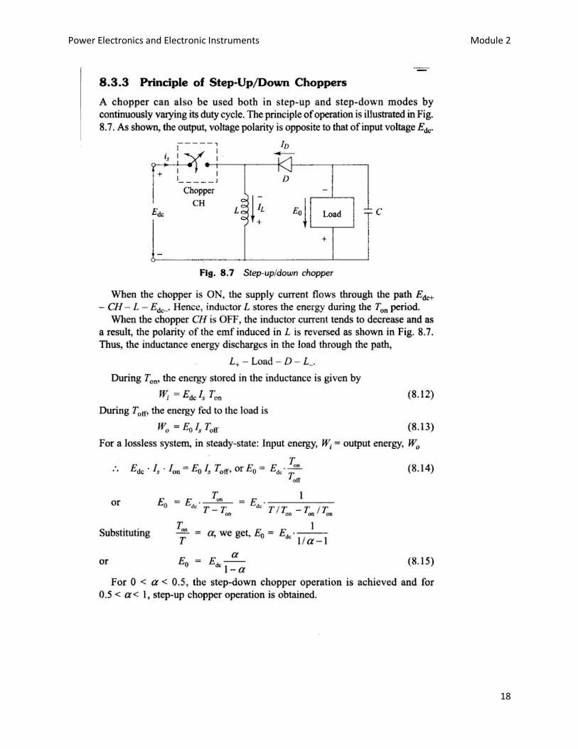
Power Electronics and Electronic Instruments Module 2
1
Module 2.
Control techniques
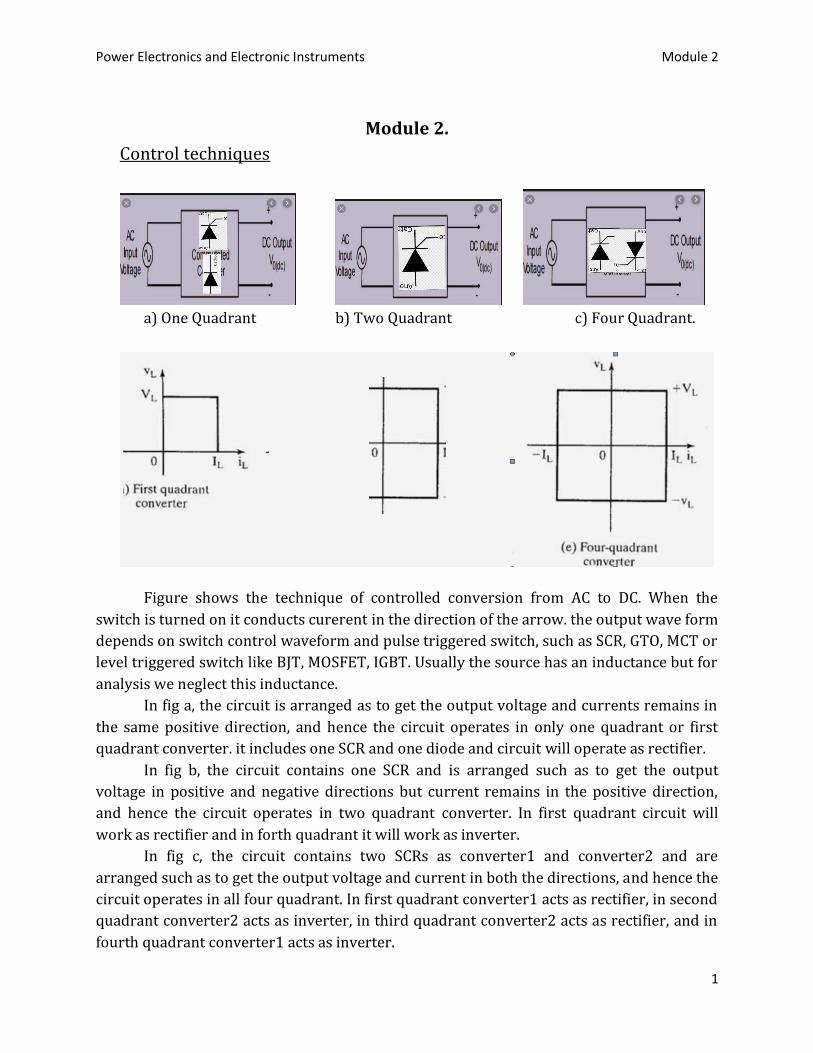
a) One Quadrant b) Two Quadrant c) Four Quadrant.
Figure shows the technique of controlled conversion from AC to DC. When the
switch is turned on it conducts curerent in the direction of the arrow. the output wave form
depends on switch control waveform and pulse triggered switch, such as SCR, GTO, MCT or
level triggered switch like BJT, MOSFET, IGBT. Usually the source has an inductance but for
analysis we neglect this inductance.
In fig a, the circuit is arranged as to get the output voltage and currents remains in
the same positive direction, and hence the circuit operates in only one quadrant or first
quadrant converter. it includes one SCR and one diode and circuit will operate as rectifier.
In fig b, the circuit contains one SCR and is arranged such as to get the output
voltage in positive and negative directions but current remains in the positive direction,
and hence the circuit operates in two quadrant converter. In first quadrant circuit will
work as rectifier and in forth quadrant it will work as inverter.
In fig c, the circuit contains two SCRs as converter1 and converter2 and are
arranged such as to get the output voltage and current in both the directions, and hence the
circuit operates in all four quadrant. In first quadrant converter1 acts as rectifier, in second
quadrant converter2 acts as inverter, in third quadrant converter2 acts as rectifier, and in
fourth quadrant converter1 acts as inverter.
Power Electronics and Electronic Instruments Module 2
2
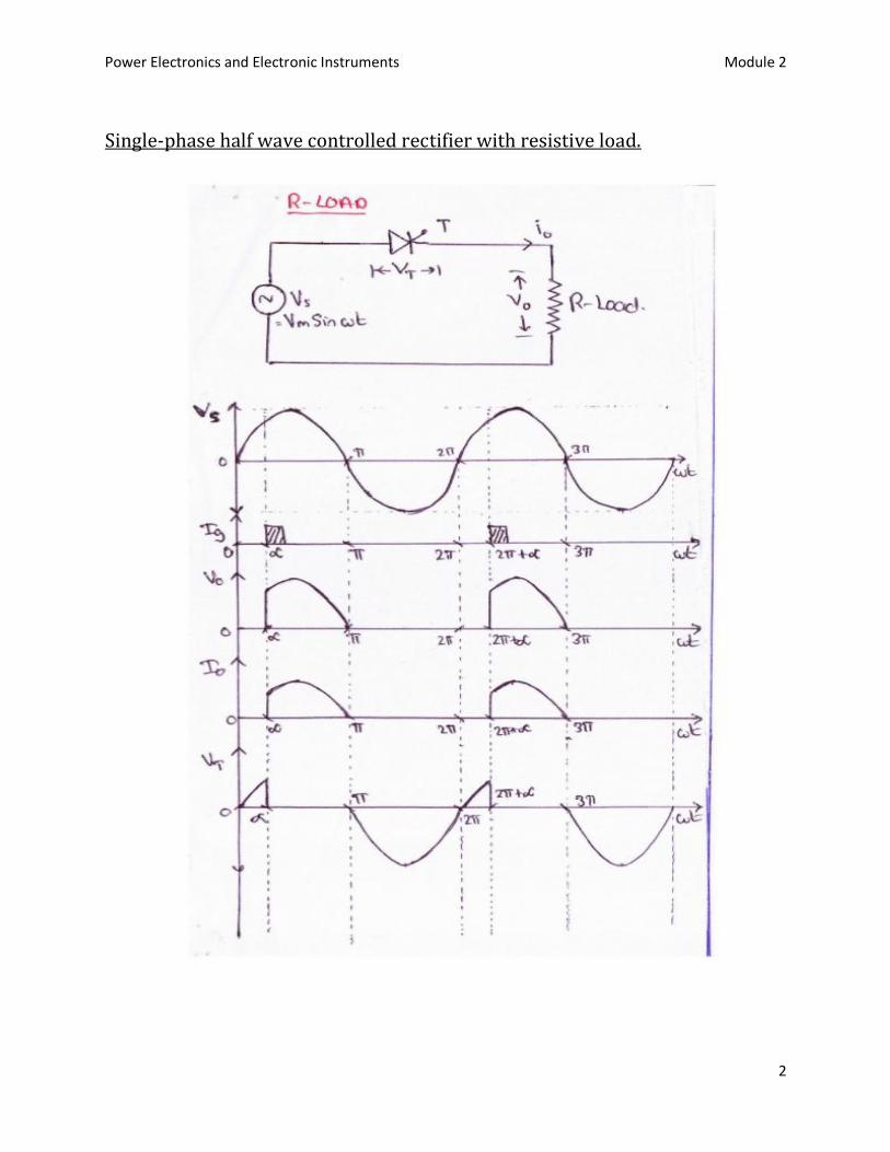
Single-phase half wave controlled rectifier with resistive load.
Power Electronics and Electronic Instruments Module 2
3
Power Electronics and Electronic Instruments Module 2
4
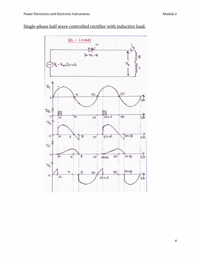
Single-phase half wave controlled rectifier with inductive load.

Power Electronics and Electronic Instruments Module 2
5
Power Electronics and Electronic Instruments Module 2
6
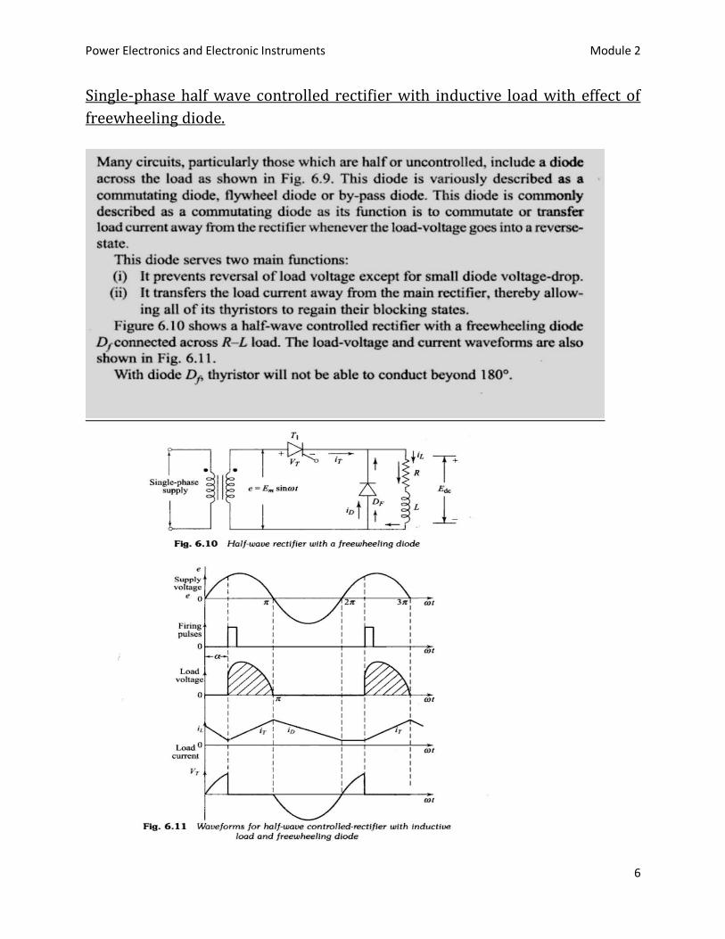
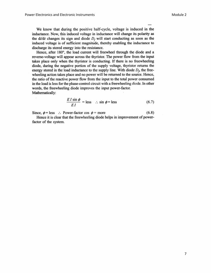
Single-phase half wave controlled rectifier with inductive load with effect of
freewheeling diode.
Power Electronics and Electronic Instruments Module 2
7
Power Electronics and Electronic Instruments Module 2
8
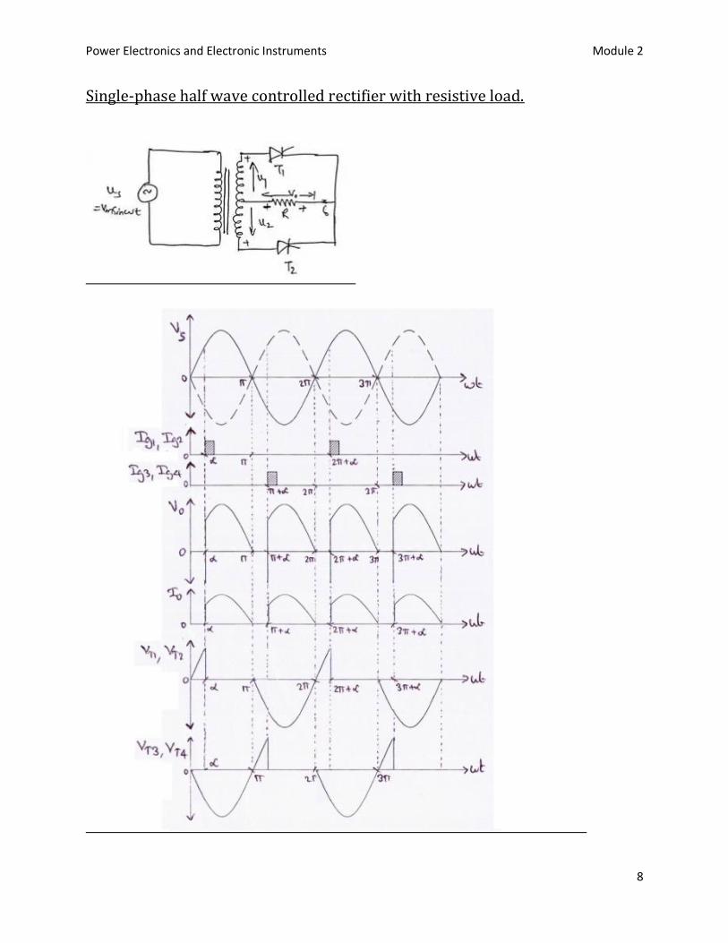
Single-phase half wave controlled rectifier with resistive load.

Power Electronics and Electronic Instruments Module 2
9
Single-phase full wave controlled rectifier with inductive load.

Power Electronics and Electronic Instruments Module 2
10
Power Electronics and Electronic Instruments Module 2
11
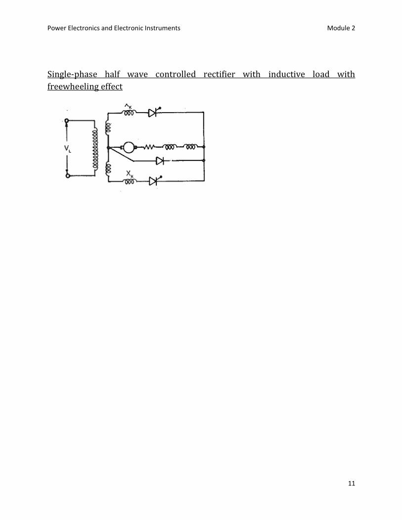
Single-phase half wave controlled rectifier with inductive load with
freewheeling effect

Power Electronics and Electronic Instruments Module 2
12
DC to DC converters (CHOPPER)
Power Electronics and Electronic Instruments Module 2
13
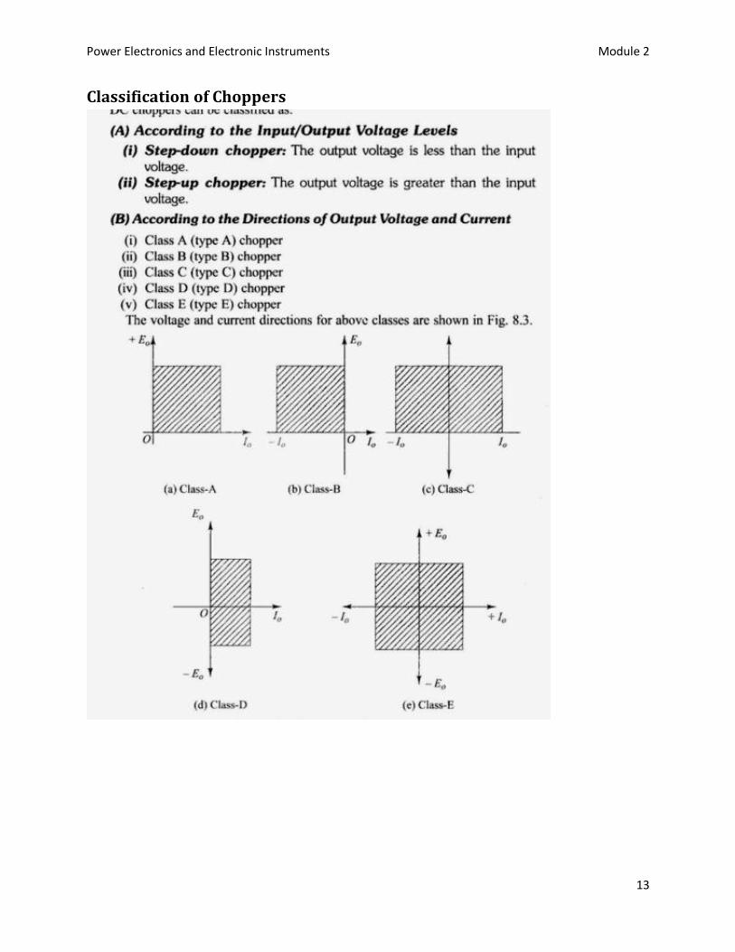
Classification of Choppers
Power Electronics and Electronic Instruments Module 2
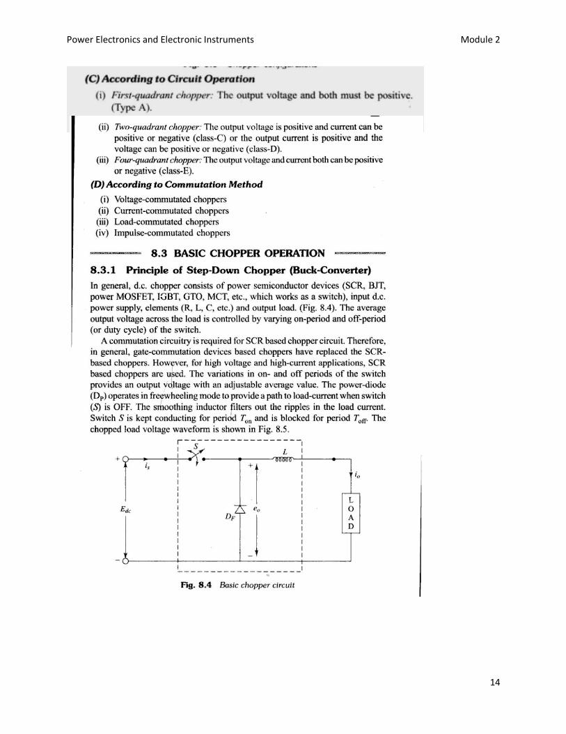
14

Power Electronics and Electronic Instruments Module 2
15
Power Electronics and Electronic Instruments Module 2
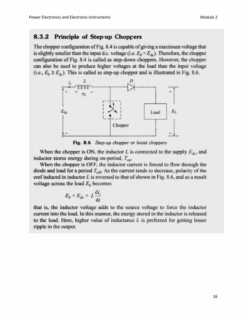
16
Power Electronics and Electronic Instruments Module 2
17
Power Electronics and Electronic Instruments Module 2
18