Embed Size (px)
Citation preview

September 2010
Modular Magnetic
Encoders
2
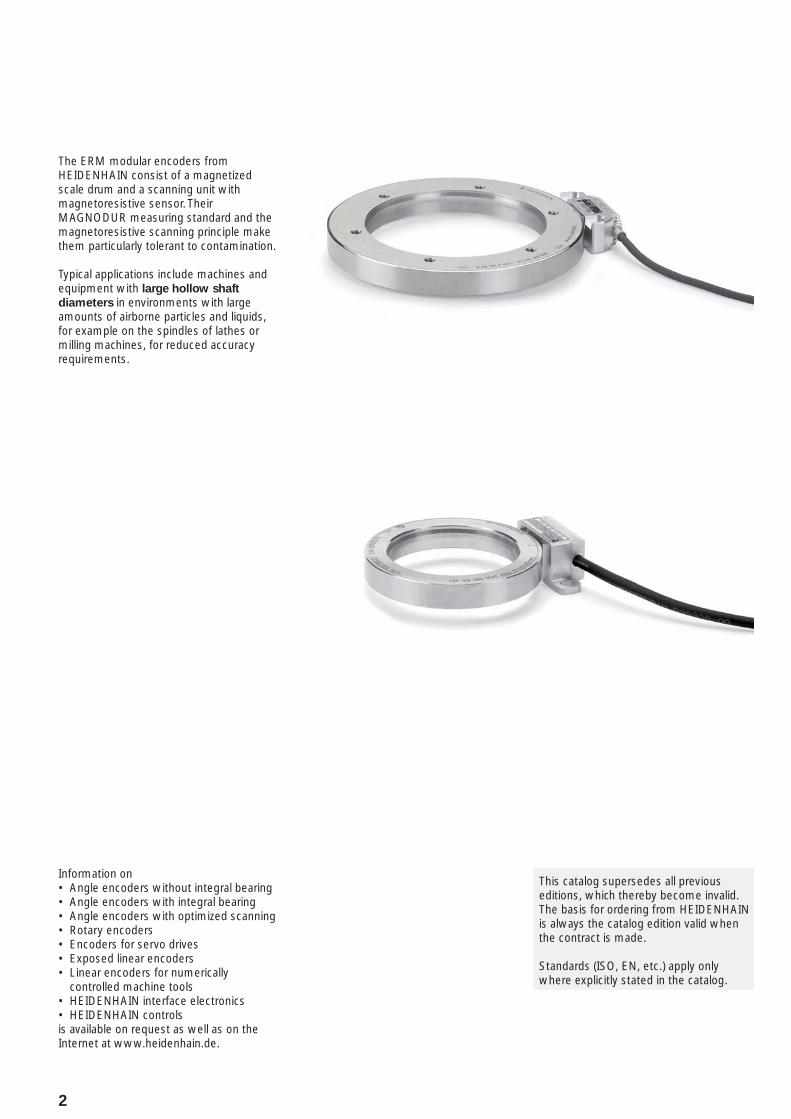
The ERM modular encoders from HEIDENHAIN consist of a magnetized scale drum and a scanning unit with magnetoresistive sensor. Their MAGNODUR measuring standard and the magnetoresistive scanning principle make them particularly tolerant to contamination.
Typical applications include machines and equipment with large hollow shaft
diameters in environments with large amounts of airborne particles and liquids, for example on the spindles of lathes or milling machines, for reduced accuracy requirements.
Information onAngle encoders without integral bearing• Angle encoders with integral bearing• Angle encoders with optimized scanning• Rotary encoders• Encoders for servo drives• Exposed linear encoders• Linear encoders for numerically • controlled machine toolsHEIDENHAIN interface electronics• HEIDENHAIN controls•
is available on request as well as on the Internet at www.heidenhain.de.
This catalog supersedes all previous editions, which thereby become invalid. The basis for ordering from HEIDENHAIN is always the catalog edition valid when the contract is made.
Standards (ISO, EN, etc.) apply only where explicitly stated in the catalog.

Contents
Overview
Selection Guide 4
Range of Applications 6
Technical Characteristics
Measuring Principle Measuring Standard 7
Magnetic Scanning 7
Incremental Measuring Method 7
Measuring Accuracy 8
Mechanical Design Types and Mounting 10
General Mechanical Information 11
Specifi cations
Modular Encoder
With Incremental Interface ERM 200 Series 12
For very high speeds, with incremental interface
ERM 2400 Series
ERM 2900 Series14
With Purely Serial EnDat Interface ERM 2410 Series 16
Electrical Connection
Interfaces Incremental Signals » 1 VPP 18
Incremental Signals « TTL 20
EnDat 22
Cables and Connecting Elements 24
General Electrical Specifi cations 26
HEIDENHAIN Measuring Equipment 30
4
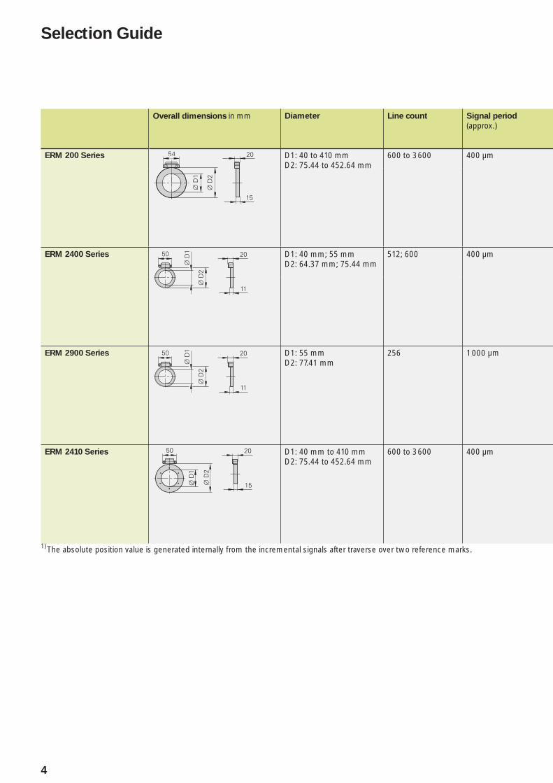
Overall dimensions in mm Diameter Line count Signal period
(approx.)
ERM 200 Series D1: 40 to 410 mmD2: 75.44 to 452.64 mm
600 to 3 600 400 µm
ERM 2400 Series D1: 40 mm; 55 mmD2: 64.37 mm; 75.44 mm
512; 600 400 µm
ERM 2900 Series D1: 55 mmD2: 77.41 mm
256 1 000 µm
ERM 2410 Series D1: 40 mm to 410 mmD2: 75.44 to 452.64 mm
600 to 3 600 400 µm
1) The absolute position value is generated internally from the incremental signals after traverse over two reference marks.
Selection Guide
5
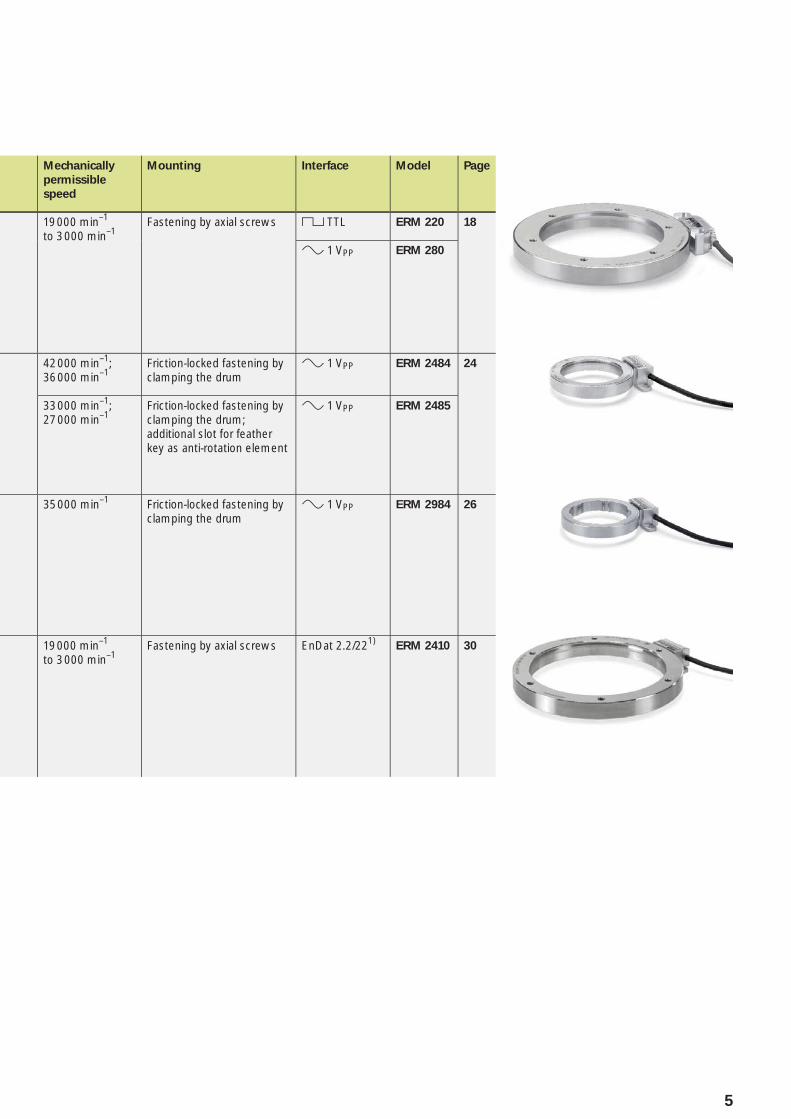
Mechanically
permissible
speed
Mounting Interface Model Page
19 000 min–1 to 3 000 min–1
Fastening by axial screws « TTL ERM 220 18
» 1 VPP ERM 280
42 000 min–1;36 000 min–1
Friction-locked fastening by clamping the drum
» 1 VPP ERM 2484 24
33 000 min–1;27 000 min–1
Friction-locked fastening by clamping the drum; additional slot for feather key as anti-rotation element
» 1 VPP ERM 2485
35 000 min–1 Friction-locked fastening by clamping the drum
» 1 VPP ERM 2984 26
19 000 min–1 to 3 000 min–1
Fastening by axial screws EnDat 2.2/221)ERM 2410 30
6
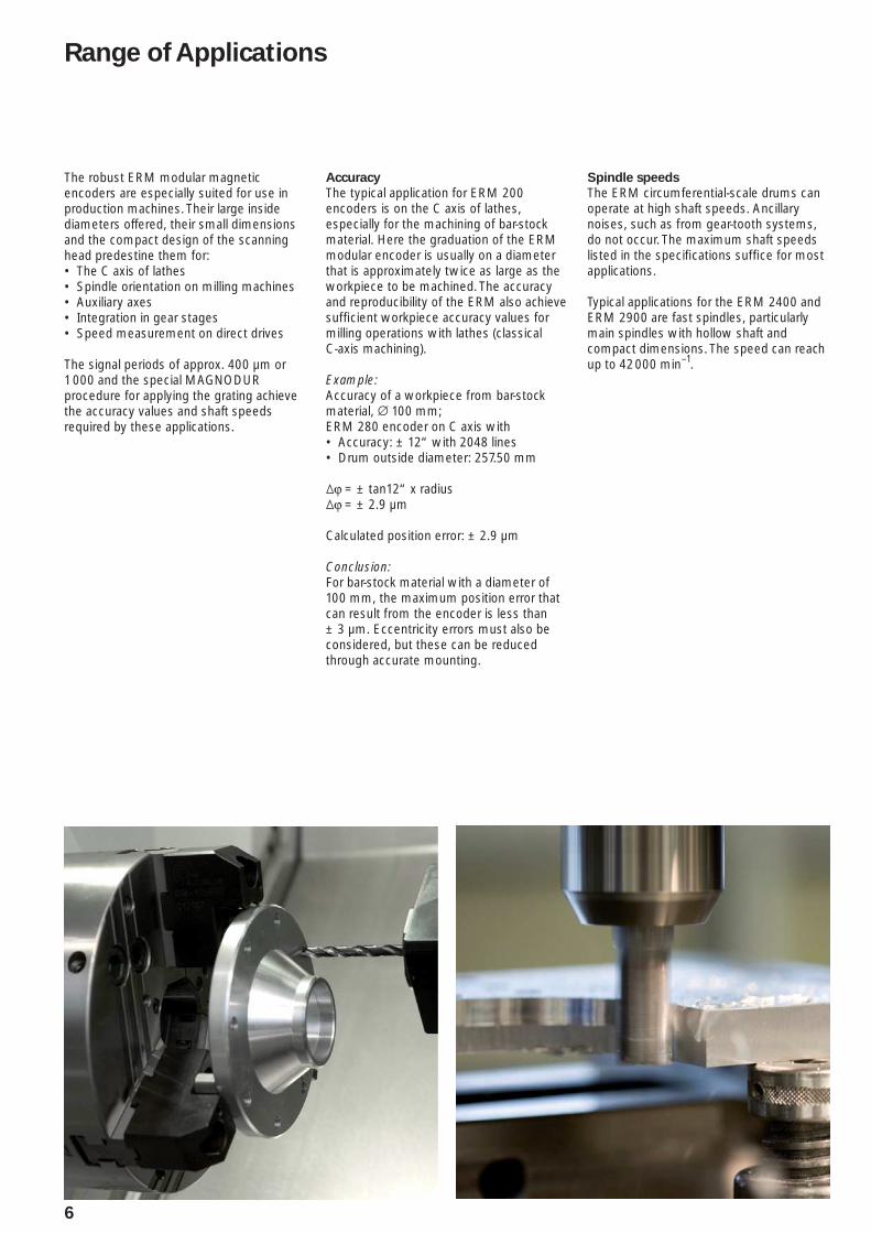
Range of Applications
Accuracy
The typical application for ERM 200 encoders is on the C axis of lathes, especially for the machining of bar-stock material. Here the graduation of the ERM modular encoder is usually on a diameter that is approximately twice as large as the workpiece to be machined. The accuracy and reproducibility of the ERM also achieve suffi cient workpiece accuracy values for milling operations with lathes (classical C-axis machining).
Example:Accuracy of a workpiece from bar-stock material, ¬ 100 mm;ERM 280 encoder on C axis with
Accuracy: ± 12“ with 2048 lines• Drum outside diameter: 257.50 mm•
¹ϕ = ± tan12“ x radius¹ϕ = ± 2.9 µm
Calculated position error: ± 2.9 µm
Conclusion:For bar-stock material with a diameter of 100 mm, the maximum position error that can result from the encoder is less than ± 3 µm. Eccentricity errors must also be considered, but these can be reduced through accurate mounting.
Spindle speeds
The ERM circumferential-scale drums can operate at high shaft speeds. Ancillary noises, such as from gear-tooth systems, do not occur. The maximum shaft speeds listed in the specifi cations suffi ce for most applications.
Typical applications for the ERM 2400 and ERM 2900 are fast spindles, particularly main spindles with hollow shaft and compact dimensions. The speed can reach up to 42 000 min–1.
The robust ERM modular magnetic encoders are especially suited for use in production machines. Their large inside diameters offered, their small dimensions and the compact design of the scanning head predestine them for:
The C axis of lathes• Spindle orientation on milling machines• Auxiliary axes• Integration in gear stages• Speed measurement on direct drives•
The signal periods of approx. 400 µm or 1 000 and the special MAGNODUR procedure for applying the grating achieve the accuracy values and shaft speeds required by these applications.

7
Measuring Principle
Measuring standard
HEIDENHAIN encoders incorporate measuring standards of periodic structures known as graduations.
Magnetic encoders use a graduation carrier of magnetizable steel alloy. A write head applies strong local magnetic fi elds in different directions to form a graduation with 400 µm or 1 000 µm (with ERM 2984) per signal period consisting of north poles and south poles (MAGNODUR process). Due to the short distance of effect of electromagnetic interaction and the very narrow scanning gaps required, fi ner magnetic graduations have signifi cantly tighter mounting tolerances.
Magnetoresistive scanning principle
Measuring standard
Scanning reticle
Magnetoresistive sensors for B+ and B– not shown
Magnetic Scanning
The permanently magnetic MAGNODUR graduation is scanned by magnetoresistive sensors. They consist of resistive tracks whose resistance changes in response to a magnetic fi eld. When a voltage is applied to the sensor and the scale drum moves relative to the scanning head, the fl owing current is modulated according to the magnetic fi eld.
The special geometric arrangement of the resistive sensors and the manufacture of the sensors on glass substrates ensure a high signal quality. In addition, the large scanning surface allows the signals to be fi ltered for harmonic waves. These are prerequisites for minimizing position errors within one signal period.
A structure on a separate track produces a reference mark signal. This makes it possible to assign this absolute position value to exactly one measuring step.
Magnetoresistive scanning is used primarily for comparatively low-accuracy applications, or for applications where the machined parts are relatively small compared to the scale drum.
Incremental measuring method
With the incremental measuring method, the graduation consists of a periodic grating structure. The position information is obtained by counting the individual increments (measuring steps) from some point of origin. The shaft speed is determined through mathematical derivation of the change in position over time.
Since an absolute reference is required to ascertain positions, the scale drums are provided with an additional track that bears a reference mark or multiple reference marks. The absolute position on the scale, established by the reference mark, is gated with exactly one measuring step. The reference mark must therefore be scanned to establish an absolute reference or to fi nd the last selected datum. On the ERM 2410, the scale drum features distance-coded reference marks. Here the absolute reference is established by scanning two neighboring reference marks (see Angle for absolute reference in the Specifi cations).
8
Measuring Accuracy
The accuracy of angular measurement is mainly determined by:
The quality of the graduation• The quality of the scanning process• The quality of the signal processing • electronicsThe eccentricity of the graduation to the • bearingThe error of the bearing• The coupling to the measured shaft•
The system accuracy given in the Specifi cations is defi ned as follows:
The system accuracy refl ects position errors within one revolution as well as those within one signal period. The extreme values of the total deviations of a position are within the system accuracy ± a.
For encoders without integral bearing, additional deviations resulting from mounting, errors in the bearing of the drive shaft, and adjustment of the scanning head must be expected. These deviations are not refl ected in the system accuracy.
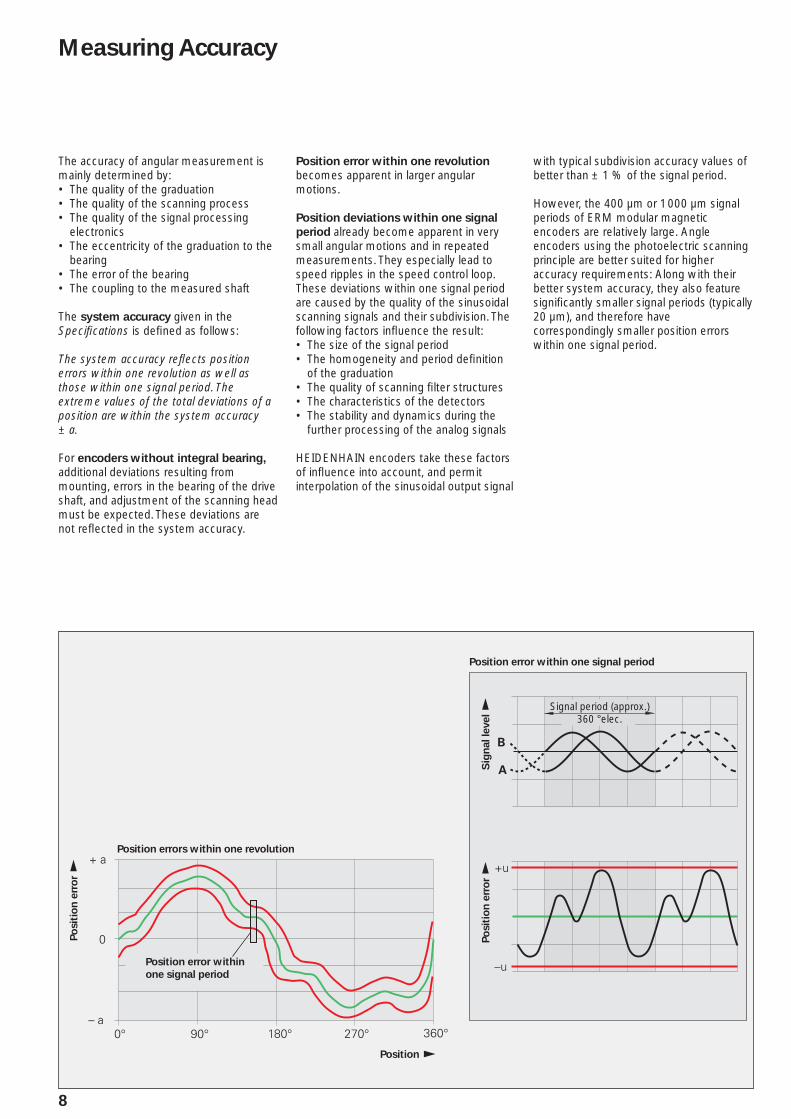
Position error within one revolution becomes apparent in larger angular motions.
Position deviations within one signal
period already become apparent in very small angular motions and in repeated measurements. They especially lead to speed ripples in the speed control loop. These deviations within one signal period are caused by the quality of the sinusoidal scanning signals and their subdivision. The following factors infl uence the result:
The size of the signal period• The homogeneity and period defi nition • of the graduationThe quality of scanning fi lter structures• The characteristics of the detectors• The stability and dynamics during the • further processing of the analog signals
HEIDENHAIN encoders take these factors of infl uence into account, and permit interpolation of the sinusoidal output signal
with typical subdivision accuracy values of better than ± 1 % of the signal period.
However, the 400 µm or 1 000 µm signal periods of ERM modular magnetic encoders are relatively large. Angle encoders using the photoelectric scanning principle are better suited for higher accuracy requirements: Along with their better system accuracy, they also feature signifi cantly smaller signal periods (typically 20 µm), and therefore have correspondingly smaller position errors within one signal period.
Position errors within one revolution
Position error within one signal period
Position
Position error within
one signal period
Po
sit
ion
err
or
Po
sit
ion
err
or
Sig
nal le
vel
Signal period (approx.)360 °elec.
�
�
�
��
�
��
���
���
��
��
��
������
��
�
���������
��
9
In addition to the system accuracy, the mounting and adjustment of the scanning head and of the scale drum normally have a signifi cant effect on the accuracy that can be achieved with encoders without integral bearings. Of particular importance are the mounting eccentricity and radial runout of the measured shaft.
In order to evaluate the total accuracy, each of the signifi cant errors must be considered individually.
1. Directional deviations of the
graduation
The extreme values of the directional deviation with respect to their mean value are shown in the Specifi cations as the graduation accuracy. The graduation accuracy and the position error within a signal period comprise the system accuracy.
2. Errors due to eccentricity of the
graduation to the bearing
Under normal circumstances, the graduation will have a certain eccentricity relative to the bearing once the ERM’s scale drum is mounted. In addition, dimensional and form deviations of the shaft can result in added eccentricity.
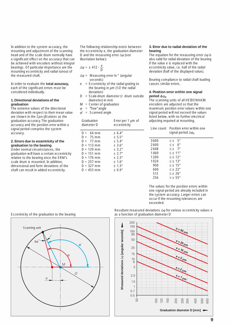
The following relationship exists between the eccentricity e, the graduation diameter D and the measuring error ¹ϕ (see illustration below):
¹ϕ = ± 412 · e
¹ϕ = Measuring error in “ (angular seconds)
e = Eccentricity of the radial grating to the bearing in µm (1/2 the radial deviation)
D = Scale-drum diameter (= drum outside diameter) in mm
M = Center of graduationϕ = "True" angleϕ‘ = Scanned angle
D
Eccentricity of the graduation to the bearing
Scanning unit
3. Error due to radial deviation of the
bearing
The equation for the measuring error ¹ϕ is also valid for radial deviation of the bearing if the value e is replaced with the eccentricity value, i.e. half of the radial deviation (half of the displayed value).
Bearing compliance to radial shaft loading causes similar errors.
4. Position error within one signal
period ¹ϕu
The scanning units of all HEIDENHAIN encoders are adjusted so that the maximum position error values within one signal period will not exceed the values listed below, with no further electrical adjusting required at mounting.
Line count Position error within one signal period ¹ϕu
3 6002 6002 0481 4001 2001 024 900 600 512 256
† ± 5“† ± 6“† ± 7“† ± 11“† ± 12“† ± 13“† ± 15“† ± 22“† ± 26“† ± 55“
The values for the position errors within one signal period are already included in the system accuracy. Larger errors can occur if the mounting tolerances are exceeded.
Graduationdiameter D
Error per 1 µm of eccentricity
D = 64 mmD = 75 mmD = 77 mmD = 113 mmD = 129 mmD = 151 mmD = 176 mmD = 257 mmD = 327 mmD = 453 mm
± 6.4“± 5.5“± 5.4“± 3.6“± 3.2“± 2.7“± 2.3“± 1.6“± 1.3“± 0.9“
Resultant measured deviations ¹ϕ for various eccentricity values e as a function of graduation diameter D
Measu
red
devia
tio
ns ¹
ϕ [a
ng
ula
r seco
nd
s]
Graduation diameter D [mm]

10
Mechanical Design Types and Mounting
Mounting
The ERM modular encoders consist of a circumferential scale drum and the corresponding scanning head. Special design features assure comparatively fast mounting and easy adjustment.
Versions
There are two different signal periods available for the ERM modular magnetic encoders (ERM 200, ERM 24x0: ca. 400 µm; ERM 2900: approx. 1 mm). This results in differing line counts for nearly identical outside diameters, making it possible to use these encoders for very different types of spindle applications.
The scale drum is available in three versions. The TTR ERM 200 and TTR ERM
200 C scale drums are fastened with axial screws. The insides of the TTR ERM 2404 and TTR ERM 2904 scale drums are smooth. Only a friction-locked connection (clamping of the drum) is to be used to prevent them from rotating unintentionally. The TTR ERM 2405 scale drums feature a keyway. The feather key is only intended for the prevention of unintentional rotation. The transmission of torque via the feather
key is not permissible. A friction-locked connection is to be used here, as with the TTR ERM 2404 scale drum. The special shape of the drum’s inside ensures stability even at the maximum permissible speeds.
Mounting the TTR ERM 200 scale drum
The circumferential scale drum is slid onto the drive shaft and fastened with screws. The scale drum is centered via the centering collar on its inner circumference. HEIDENHAIN recommends using a slight oversize on the shaft for mounting the scale drum. Only then do the rotational velocities listed in the Specifi cations apply. For easier mounting, the scale drum may be slowly warmed on a heating plate over a period of approx. 10 minutes to a temperature of at most 100 °C. In order to check the radial runout and assess the resulting deviations, testing of the rotational accuracy before mounting is recommended.
Back-off threads are used for dismounting the scale drums.
Mounting of the scale drumERM 200 scale drumTTR ERM 200 C
Mounting of the scanning heade.g. AK ERM 280
Mounting the TTR ERM 2x0x scale drum
The circumferential scale drum is slid onto the drive shaft and clamped. The scale drum is centered via the centering collar on its inner circumference. In order to keep the eccentricity of the graduation to the bearing resulting from mounting to a minimum, and the resulting deviations in accuracy as well, the gap between the shaft and centering collar should be as small as possible. The clamping of the scale drum depends on the mounting situation. The clamping force must be applied evenly over the plane surface of the drum. The necessary mounting elements depend on the design of the customer’s equipment, and are therefore the responsibility of the customer. The frictional connection must be strong enough to prevent unintentional rotation or skewing in axial and radial directions, even at high speeds and accelerations. The scale drum may not be modifi ed for this purpose, such as by drilling holes or countersinks in it.
Mounting the scanning head
In order to mount the scanning head, the spacer foil is applied to the surface of the circumferential scale drum. The scanning head is pressed against the foil and fastened. The foil is then removed.
Mounting of the scale drumERM 2404 scale drumERM 2904 scale drum
Mounting of the scale drumERM 2405 scale drum
��������
11
System tests
Encoders from HEIDENHAIN are usually integrated as components in larger systems. Such applications require comprehensive tests of the entire
system regardless of the specifi cations of the encoder.
The specifi cations given in the brochure apply to the specifi c encoder, not to the complete system. Any operation of the encoder outside of the specifi ed range or for any other than the intended applications is at the user’s own risk.In safety-related systems, the higher-level system must verify the position value of the encoder after switch-on.
Mounting
Work steps to be performed and dimensions to be maintained during mounting are specifi ed solely in the mounting instructions supplied with the unit. All data in this catalog regarding mounting are therefore provisional and not binding; they do not become terms of a contract.
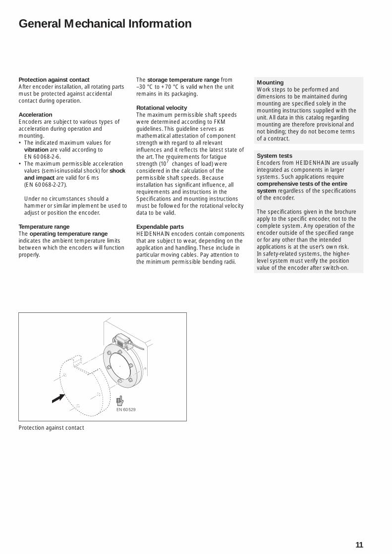
Protection against contact
After encoder installation, all rotating parts must be protected against accidental contact during operation.
Acceleration
Encoders are subject to various types of acceleration during operation and mounting.
The indicated maximum values for • vibration are valid according to EN 60 068-2-6.The maximum permissible acceleration • values (semi-sinusoidal shock) for shock
and impact are valid for 6 ms (EN 60 068-2-27).
Under no circumstances should a hammer or similar implement be used to adjust or position the encoder.
Temperature range
The operating temperature range indicates the ambient temperature limits between which the encoders will function properly.
Protection against contact
The storage temperature range from –30 °C to +70 °C is valid when the unit remains in its packaging.
Rotational velocity
The maximum permissible shaft speeds were determined according to FKM guidelines. This guideline serves as mathematical attestation of component strength with regard to all relevant infl uences and it refl ects the latest state of the art. The requirements for fatigue strength (107 changes of load) were considered in the calculation of the permissible shaft speeds. Because installation has signifi cant infl uence, all requirements and instructions in the Specifi cations and mounting instructions must be followed for the rotational velocity data to be valid.
Expendable parts
HEIDENHAIN encoders contain components that are subject to wear, depending on the application and handling. These include in particular moving cables. Pay attention to the minimum permissible bending radii.
General Mechanical Information
���������������� �������� ����� !�����"�#�����
12
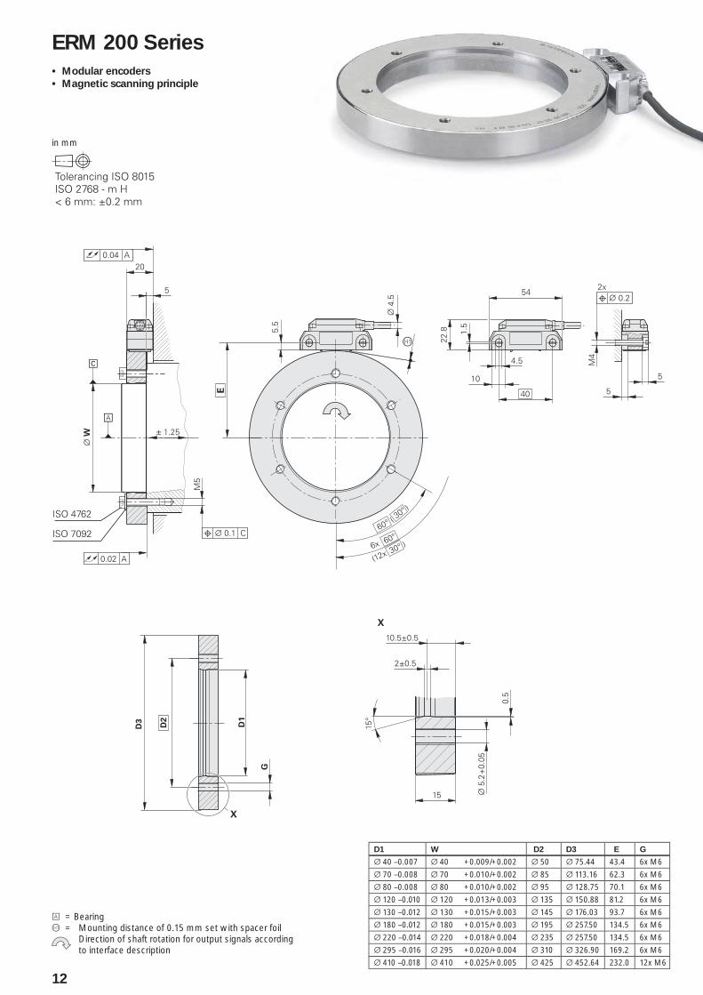
A = BearingÀ = Mounting distance of 0.15 mm set with spacer foil Direction of shaft rotation for output signals according
to interface description
in mm
ERM 200 Series
Modular encoders•
Magnetic scanning principle•
D1 W D2 D3 E G
¬ 40 –0.007 ¬ 40 +0.009/+0.002 ¬ 50 ¬ 75.44 43.4 6x M6
¬ 70 –0.008 ¬ 70 +0.010/+0.002 ¬ 85 ¬ 113.16 62.3 6x M6
¬ 80 –0.008 ¬ 80 +0.010/+0.002 ¬ 95 ¬ 128.75 70.1 6x M6
¬ 120 –0.010 ¬ 120 +0.013/+0.003 ¬ 135 ¬ 150.88 81.2 6x M6
¬ 130 –0.012 ¬ 130 +0.015/+0.003 ¬ 145 ¬ 176.03 93.7 6x M6
¬ 180 –0.012 ¬ 180 +0.015/+0.003 ¬ 195 ¬ 257.50 134.5 6x M6
¬ 220 –0.014 ¬ 220 +0.018/+0.004 ¬ 235 ¬ 257.50 134.5 6x M6
¬ 295 –0.016 ¬ 295 +0.020/+0.004 ¬ 310 ¬ 326.90 169.2 6x M6
¬ 410 –0.018 ¬ 410 +0.025/+0.005 ¬ 425 ¬ 452.64 232.0 12x M6
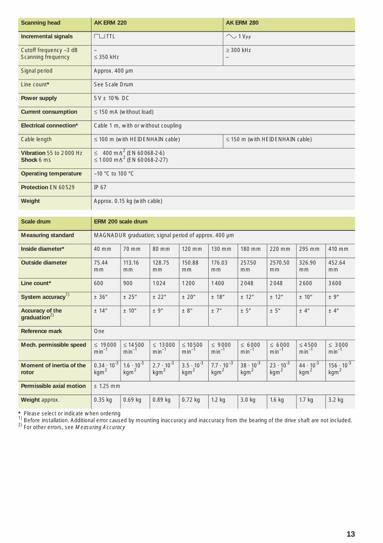
13
Scanning head AK ERM 220 AK ERM 280
Incremental signals « TTL » 1 VPP
Cutoff frequency –3 dBScanning frequency
–† 350 kHz
‡ 300 kHz–
Signal period Approx. 400 µm
Line count* See Scale Drum
Power supply 5 V ± 10 % DC
Current consumption † 150 mA (without load)
Electrical connection* Cable 1 m, with or without coupling
Cable length † 100 m (with HEIDENHAIN cable) † 150 m (with HEIDENHAIN cable)
Vibration 55 to 2000 HzShock 6 ms
† 400 m/s2 (EN 60 068-2-6)† 1000 m/s2 (EN 60 068-2-27)
Operating temperature –10 °C to 100 °C
Protection EN 60 529 IP 67
Weight Approx. 0.15 kg (with cable)
Scale drum ERM 200 scale drum
Measuring standard MAGNADUR graduation; signal period of approx. 400 µm
Inside diameter* 40 mm 70 mm 80 mm 120 mm 130 mm 180 mm 220 mm 295 mm 410 mm
Outside diameter 75.44mm
113.16 mm
128.75 mm
150.88 mm
176.03 mm
257.50 mm
2570.50 mm
326.90 mm
452.64 mm
Line count* 600 900 1 024 1 200 1 400 2 048 2 048 2 600 3 600
System accuracy1) ± 36“ ± 25“ ± 22“ ± 20“ ± 18“ ± 12“ ± 12“ ± 10“ ± 9“
Accuracy of the
graduation2)
± 14“ ± 10“ ± 9“ ± 8“ ± 7“ ± 5“ ± 5“ ± 4“ ± 4“
Reference mark One
Mech. permissible speed † 19 000 min–1
† 14 500 min–1
† 13 000 min–1
† 10 500 min–1
† 9 000 min–1
† 6 000 min–1
† 6 000 min–1
† 4 500 min–1
† 3 000 min–1
Moment of inertia of the
rotor
0.34 · 10-3 kgm2
1.6 · 10-3 kgm2
2.7 · 10-3 kgm2
3.5 · 10-3 kgm2
7.7 · 10–3 kgm2
38 · 10-3 kgm2
23 · 10-3 kgm2
44 · 10-3 kgm2
156 · 10-3 kgm2
Permissible axial motion ± 1.25 mm
Weight approx. 0.35 kg 0.69 kg 0.89 kg 0.72 kg 1.2 kg 3.0 kg 1.6 kg 1.7 kg 3.2 kg
* Please select or indicate when ordering1) Before installation. Additional error caused by mounting inaccuracy and inaccuracy from the bearing of the drive shaft are not included.2) For other errors, see Measuring Accuracy
$
�
$��
%�%��
��
��� ��
�
#�������������%���%� &���'
����%�����'����%
�
��
���
�
�
��
�
�
�
�
$"��
#���
���
�
$
�(��)�*
�������
������$��+
���������������� �������� ����� !�����"�#�����
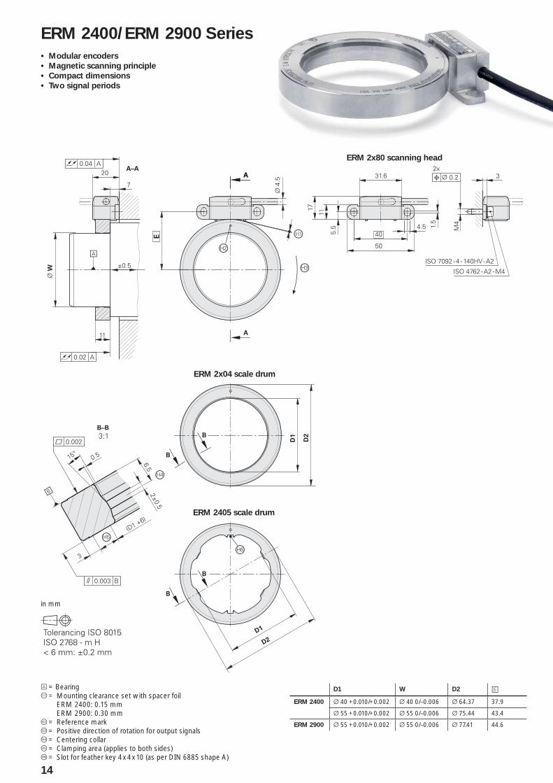
14
A = BearingÀ = Mounting clearance set with spacer foil
ERM 2400: 0.15 mmERM 2900: 0.30 mm
Á = Reference mark = Positive direction of rotation for output signalsà = Centering collarÄ = Clamping area (applies to both sides)Å = Slot for feather key 4 x 4 x 10 (as per DIN 6885 shape A)
in mm
ERM 2400/ERM 2900 Series
Modular encoders•
Magnetic scanning principle•
Compact dimensions•
Two signal periods•
D1 W D2 EERM 2400 ¬ 40 +0.010/+0.002 ¬ 40 0/–0.006 ¬ 64.37 37.9
¬ 55 +0.010/+0.002 ¬ 55 0/–0.006 ¬ 75.44 43.4
ERM 2900 ¬ 55 +0.010/+0.002 ¬ 55 0/–0.006 ¬ 77.41 44.6
ERM 2x80 scanning head
ERM 2x04 scale drum
ERM 2405 scale drum
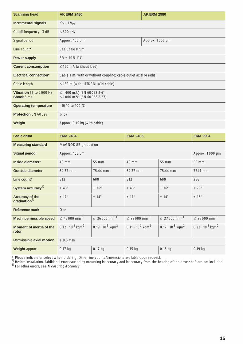
15
Scanning head AK ERM 2480 AK ERM 2980
Incremental signals » 1 VPP
Cutoff frequency –3 dB † 300 kHz
Signal period Approx. 400 µm Approx. 1 000 µm
Line count* See Scale Drum
Power supply 5 V ± 10 % DC
Current consumption † 150 mA (without load)
Electrical connection* Cable 1 m, with or without coupling; cable outlet axial or radial
Cable length † 150 m (with HEIDENHAIN cable)
Vibration 55 to 2000 HzShock 6 ms
† 400 m/s2 (EN 60 068-2-6)† 1000 m/s2 (EN 60 068-2-27)
Operating temperature –10 °C to 100 °C
Protection EN 60 529 IP 67
Weight Approx. 0.15 kg (with cable)
Scale drum ERM 2404 ERM 2405 ERM 2904
Measuring standard MAGNODUR graduation
Signal period Approx. 400 µm Approx. 1 000 µm
Inside diameter* 40 mm 55 mm 40 mm 55 mm 55 mm
Outside diameter 64.37 mm 75.44 mm 64.37 mm 75.44 mm 77.41 mm
Line count* 512 600 512 600 256
System accuracy1) ± 43“ ± 36“ ± 43“ ± 36“ ± 70“
Accuracy of the
graduation2)
± 17“ ± 14“ ± 17“ ± 14“ ± 15“
Reference mark One
Mech. permissible speed † 42 000 min–1 † 36 000 min–1 † 33 000 min–1 † 27 000 min–1 † 35 000 min–1
Moment of inertia of the
rotor
0.12 · 10-3 kgm2 0.19 · 10-3 kgm2 0.11 · 10-3 kgm2 0.17 · 10-3 kgm2 0.22 · 10-3 kgm2
Permissible axial motion ± 0.5 mm
Weight approx. 0.17 kg 0.17 kg 0.15 kg 0.15 kg 0.19 kg
* Please indicate or select when ordering. Other line counts/dimensions available upon request.1) Before installation. Additional error caused by mounting inaccuracy and inaccuracy from the bearing of the drive shaft are not included.2) For other errors, see Measuring Accuracy
�
���
$��
%�
%��
��
���
��
��
�
�����������
��
$�,
(*
��,
$�,
-
(
*��,
�-
���������
$�����������
�
���
���������������� �������� ����� !�����"�#�����
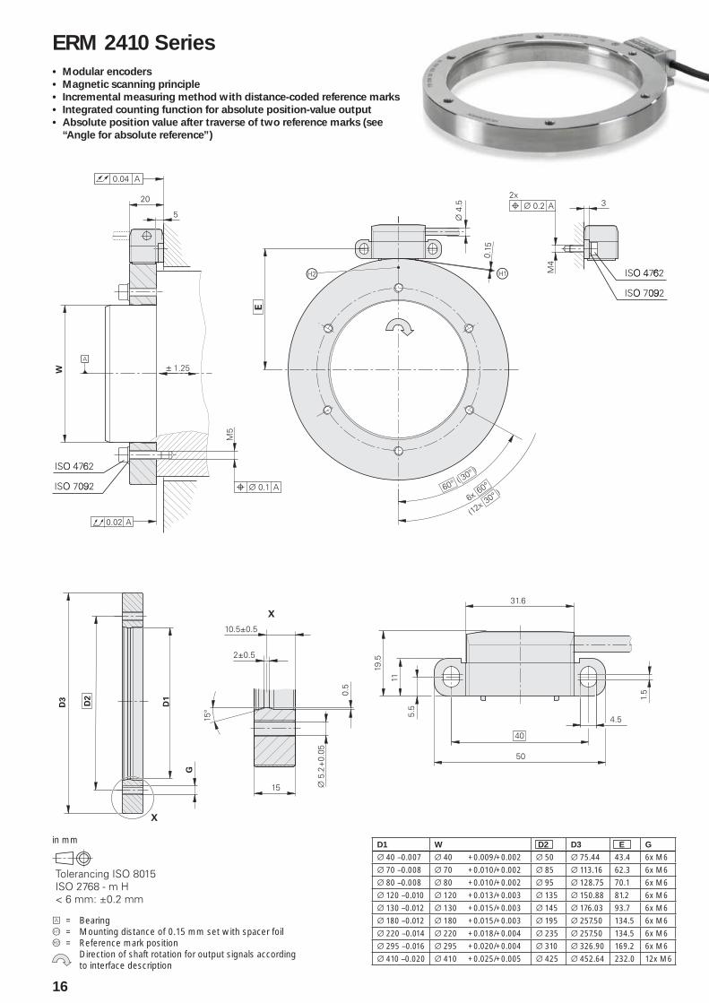
16
A = BearingÀ = Mounting distance of 0.15 mm set with spacer foilÁ = Reference mark position Direction of shaft rotation for output signals according
to interface description
in mm
ERM 2410 Series
Modular encoders•
Magnetic scanning principle•
Incremental measuring method with distance-coded reference marks•
Integrated counting function for absolute position-value output•
Absolute position value after traverse of two reference marks (see •
“Angle for absolute reference”)
D1 W D2 D3 E G
¬ 40 –0.007 ¬ 40 +0.009/+0.002 ¬ 50 ¬ 75.44 43.4 6x M6
¬ 70 –0.008 ¬ 70 +0.010/+0.002 ¬ 85 ¬ 113.16 62.3 6x M6
¬ 80 –0.008 ¬ 80 +0.010/+0.002 ¬ 95 ¬ 128.75 70.1 6x M6
¬ 120 –0.010 ¬ 120 +0.013/+0.003 ¬ 135 ¬ 150.88 81.2 6x M6
¬ 130 –0.012 ¬ 130 +0.015/+0.003 ¬ 145 ¬ 176.03 93.7 6x M6
¬ 180 –0.012 ¬ 180 +0.015/+0.003 ¬ 195 ¬ 257.50 134.5 6x M6
¬ 220 –0.014 ¬ 220 +0.018/+0.004 ¬ 235 ¬ 257.50 134.5 6x M6
¬ 295 –0.016 ¬ 295 +0.020/+0.004 ¬ 310 ¬ 326.90 169.2 6x M6
¬ 410 –0.020 ¬ 410 +0.025/+0.005 ¬ 425 ¬ 452.64 232.0 12x M6
17
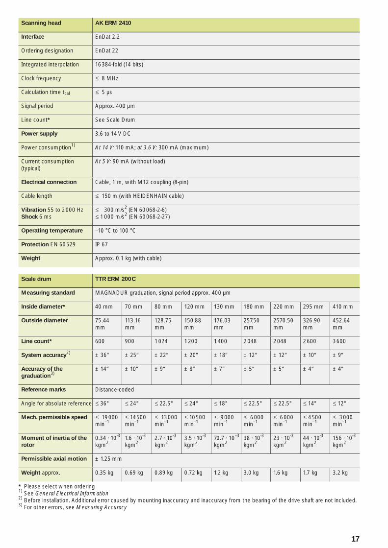
Scanning head AK ERM 2410
Interface EnDat 2.2
Ordering designation EnDat 22
Integrated interpolation 16 384-fold (14 bits)
Clock frequency † 8 MHz
Calculation time tcal † 5 µs
Signal period Approx. 400 µm
Line count* See Scale Drum
Power supply 3.6 to 14 V DC
Power consumption1) At 14 V: 110 mA; at 3.6 V: 300 mA (maximum)
Current consumption (typical)
At 5 V: 90 mA (without load)
Electrical connection Cable, 1 m, with M12 coupling (8-pin)
Cable length † 150 m (with HEIDENHAIN cable)
Vibration 55 to 2 000 HzShock 6 ms
† 300 m/s2 (EN 60 068-2-6)† 1000 m/s2 (EN 60 068-2-27)
Operating temperature –10 °C to 100 °C
Protection EN 60 529 IP 67
Weight Approx. 0.1 kg (with cable)
Scale drum TTR ERM 200 C
Measuring standard MAGNADUR graduation, signal period approx. 400 µm
Inside diameter* 40 mm 70 mm 80 mm 120 mm 130 mm 180 mm 220 mm 295 mm 410 mm
Outside diameter 75.44mm
113.16 mm
128.75 mm
150.88 mm
176.03 mm
257.50 mm
2570.50 mm
326.90 mm
452.64 mm
Line count* 600 900 1 024 1 200 1 400 2 048 2 048 2 600 3 600
System accuracy2) ± 36“ ± 25“ ± 22“ ± 20“ ± 18“ ± 12“ ± 12“ ± 10“ ± 9“
Accuracy of the
graduation3)
± 14“ ± 10“ ± 9“ ± 8“ ± 7“ ± 5“ ± 5“ ± 4“ ± 4“
Reference marks Distance-coded
Angle for absolute reference † 36° † 24° † 22.5° † 24° † 18° † 22.5° † 22.5° † 14° † 12°
Mech. permissible speed † 19 000 min–1
† 14 500 min–1
† 13 000 min–1
† 10 500 min–1
† 9 000 min–1
† 6 000 min–1
† 6 000 min–1
† 4 500 min–1
† 3 000 min–1
Moment of inertia of the
rotor
0.34 · 10-3 kgm2
1.6 · 10-3 kgm2
2.7 · 10-3 kgm2
3.5 · 10-3 kgm2
70.7 · 10–3 kgm2
38 · 10-3 kgm2
23 · 10-3 kgm2
44 · 10-3 kgm2
156 · 10-3 kgm2
Permissible axial motion ± 1.25 mm
Weight approx. 0.35 kg 0.69 kg 0.89 kg 0.72 kg 1.2 kg 3.0 kg 1.6 kg 1.7 kg 3.2 kg
* Please select when ordering1) See General Electrical Information2) Before installation. Additional error caused by mounting inaccuracy and inaccuracy from the bearing of the drive shaft are not included.3) For other errors, see Measuring Accuracy
18
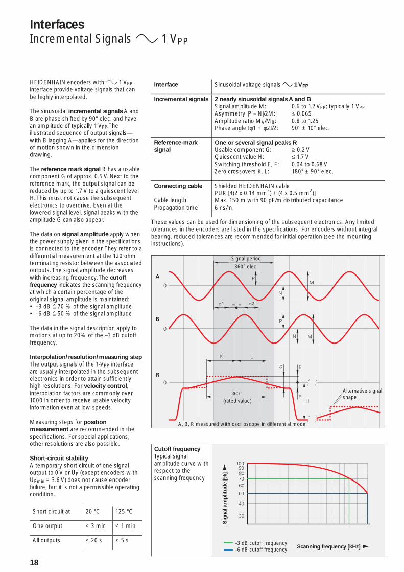
Signal period360° elec.
(rated value)
A, B, R measured with oscilloscope in differential mode
Interfaces
Incremental Signals » 1 VPP
HEIDENHAIN encoders with » 1 VPP interface provide voltage signals that can be highly interpolated.
The sinusoidal incremental signals A and B are phase-shifted by 90° elec. and have an amplitude of typically 1 VPP. The illustrated sequence of output signals—with B lagging A—applies for the direction of motion shown in the dimension drawing.
The reference mark signal R has a usable component G of approx. 0.5 V. Next to the reference mark, the output signal can be reduced by up to 1.7 V to a quiescent level H. This must not cause the subsequent electronics to overdrive. Even at the lowered signal level, signal peaks with the amplitude G can also appear.
The data on signal amplitude apply when the power supply given in the specifi cations is connected to the encoder. They refer to a differential measurement at the 120 ohm terminating resistor between the associated outputs. The signal amplitude decreases with increasing frequency. The cutoff
frequency indicates the scanning frequency at which a certain percentage of the original signal amplitude is maintained:
–3 dB • ƒ 70 % of the signal amplitude–6 dB • ƒ 50 % of the signal amplitude
The data in the signal description apply to motions at up to 20% of the –3 dB cutoff frequency.
Interpolation/resolution/measuring step
The output signals of the 1-VPP interface are usually interpolated in the subsequent electronics in order to attain suffi ciently high resolutions. For velocity control, interpolation factors are commonly over 1000 in order to receive usable velocity information even at low speeds.
Measuring steps for position
measurement are recommended in the specifi cations. For special applications, other resolutions are also possible.
Short-circuit stability
A temporary short circuit of one signal output to 0 V or UP (except encoders with UPmin = 3.6 V) does not cause encoder failure, but it is not a permissible operating condition.
Short circuit at 20 °C 125 °C
One output < 3 min < 1 min
All outputs < 20 s < 5 s
Interface Sinusoidal voltage signals » 1 VPP
Incremental signals 2 nearly sinusoidal signals A and B
Signal amplitude M: 0.6 to 1.2 VPP; typically 1 VPPAsymmetry |P – N|/2M: † 0.065Amplitude ratio MA/MB: 0.8 to 1.25Phase angle Iϕ1 + ϕ2I/2: 90° ± 10° elec.
Reference-mark
signal
One or several signal peaks R
Usable component G: ‡ 0.2 VQuiescent value H: † 1.7 VSwitching threshold E, F: 0.04 to 0.68 VZero crossovers K, L: 180° ± 90° elec.
Connecting cable
Cable lengthPropagation time
Shielded HEIDENHAIN cablePUR [4(2 x 0.14 mm2) + (4 x 0.5 mm2)]Max. 150 m with 90 pF/m distributed capacitance6 ns/m
These values can be used for dimensioning of the subsequent electronics. Any limited tolerances in the encoders are listed in the specifi cations. For encoders without integral bearing, reduced tolerances are recommended for initial operation (see the mounting instructions).
Alternative signal shape
Cutoff frequency
Typical signal amplitude curve with respect to the scanning frequency
Sig
nal am
plitu
de [
%]
Scanning frequency [kHz]–3 dB cutoff frequency–6 dB cutoff frequency
19
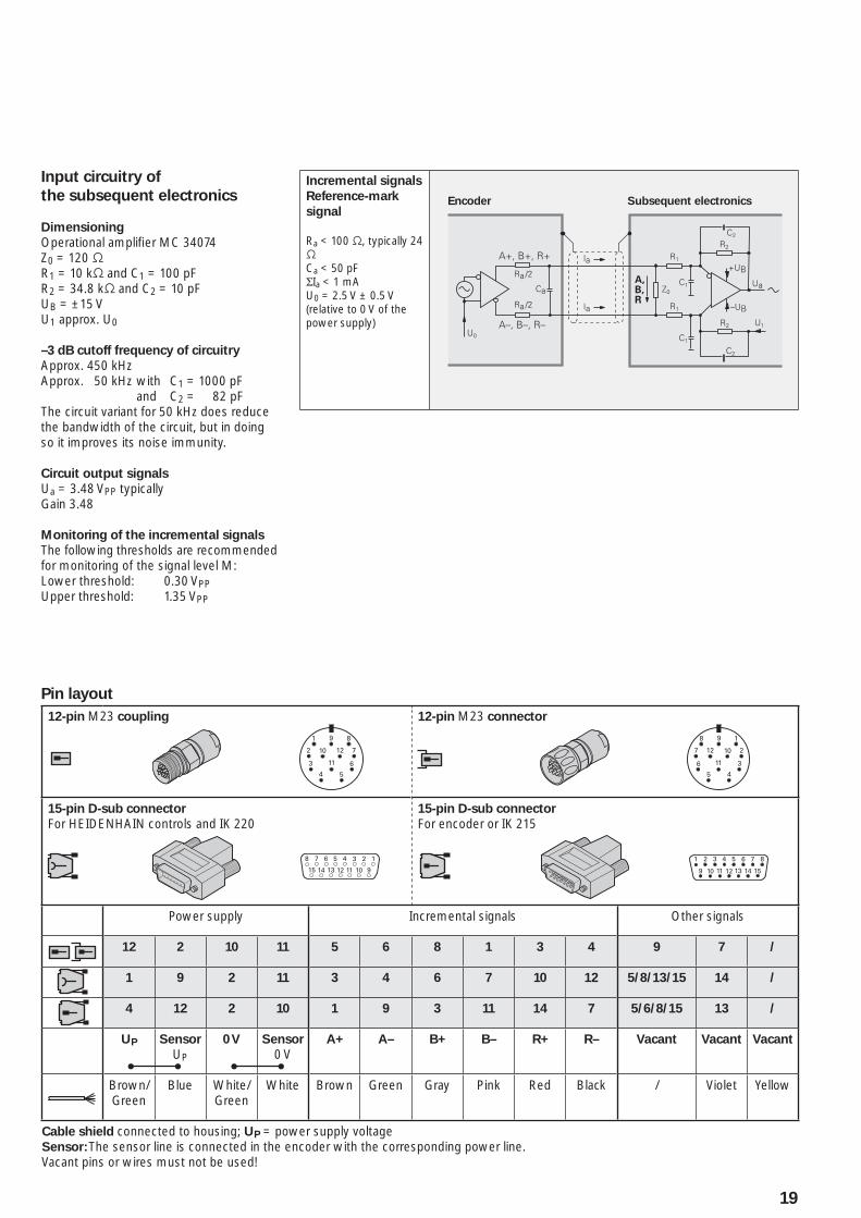
Input circuitry of
the subsequent electronics
Dimensioning
Operational amplifi er MC 34074Z0 = 120 −R1 = 10 k− and C1 = 100 pFR2 = 34.8 k− and C2 = 10 pFUB = ±15 VU1 approx. U0
–3 dB cutoff frequency of circuitry
Approx. 450 kHzApprox. 50 kHz with C1 = 1000 pF and C2 = 82 pFThe circuit variant for 50 kHz does reduce the bandwidth of the circuit, but in doing so it improves its noise immunity.
Circuit output signals
Ua = 3.48 VPP typicallyGain 3.48
Monitoring of the incremental signals
The following thresholds are recommended for monitoring of the signal level M:Lower threshold: 0.30 VPPUpper threshold: 1.35 VPP
Incremental signals
Reference-mark
signal
Ra < 100 −, typically 24 −Ca < 50 pFΣIa < 1 mAU0 = 2.5 V ± 0.5 V(relative to 0 V of the power supply)
Encoder Subsequent electronics
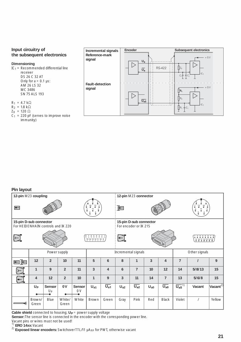
Pin layout
12-pin M23 coupling 12-pin M23 connector
15-pin D-sub connector
For HEIDENHAIN controls and IK 22015-pin D-sub connector
For encoder or IK 215
Power supply Incremental signals Other signals
12 2 10 11 5 6 8 1 3 4 9 7 /
1 9 2 11 3 4 6 7 10 12 5/8/13/15 14 /
4 12 2 10 1 9 3 11 14 7 5/6/8/15 13 /
UP Sensor
UP
0 V Sensor
0 VA+ A– B+ B– R+ R– Vacant Vacant Vacant
Brown/Green
Blue White/Green
White Brown Green Gray Pink Red Black / Violet Yellow
Cable shield connected to housing; UP = power supply voltageSensor: The sensor line is connected in the encoder with the corresponding power line.Vacant pins or wires must not be used!
20
Interfaces
Incremental Signals « TTL
HEIDENHAIN encoders with « TTL interface incorporate electronics that digitize sinusoidal scanning signals with or without interpolation.
The incremental signals are transmitted as the square-wave pulse trains Ua1 and Ua2, phase-shifted by 90° elec. The reference mark signal consists of one or more reference pulses Ua0, which are gated with the incremental signals. In addition, the integrated electronics produce their inverted signals , £ and ¤ for noise-proof transmission. The illustrated sequence of output signals—with Ua2 lagging Ua1—applies to the direction of motion shown in the dimension drawing.
The fault-detection signal ¥ indicates fault conditions such as breakage of the power line or failure of the light source. It can be used for such purposes as machine shut-off during automated production.
The distance between two successive edges of the incremental signals Ua1 and Ua2 through 1-fold, 2-fold or 4-fold evaluation is one measuring step.
The subsequent electronics must be designed to detect each edge of the square-wave pulse. The minimum edge
separation a listed in the Specifi cations applies to the illustrated input circuitry with a cable length of 1 m, and refers to a measurement at the output of the differential line receiver. Propagation-time differences in cables additionally reduce the edge separation by 0.2 ns per meter of cable length. To prevent counting errors, design the subsequent electronics to process as little as 90 % of the resulting edge separation. The max. permissible shaft speed or traversing velocity must never be exceeded.
The permissible cable length for transmission of the TTL square-wave signals to the subsequent electronics depends on the edge separation a. It is at most 100 m, or 50 m for the fault detection signal. This requires, however, that the power supply (see Specifi cations) be ensured at the encoder. The sensor lines can be used to measure the voltage at the encoder and, if required, correct it with an automatic control system (remote sense power supply).
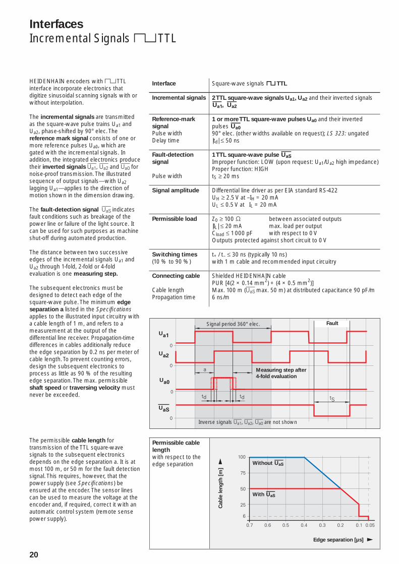
Interface Square-wave signals « TTL
Incremental signals 2 TTL square-wave signals Ua1, Ua2 and their inverted signals , £
Reference-mark
signal
Pulse widthDelay time
1 or more TTL square-wave pulses Ua0 and their inverted pulses ¤ 90° elec. (other widths available on request); LS 323: ungated|td| † 50 ns
Fault-detection
signal
Pulse width
1 TTL square-wave pulse ¥Improper function: LOW (upon request: Ua1/Ua2 high impedance)Proper function: HIGHtS ‡ 20 ms
Signal amplitude Differential line driver as per EIA standard RS-422UH ‡ 2.5 V at –IH = 20 mAUL † 0.5 V at IL = 20 mA
Permissible load Z0 ‡ 100 − between associated outputs|IL| † 20 mA max. load per outputCload † 1000 pF with respect to 0 VOutputs protected against short circuit to 0 V
Switching times
(10 % to 90 %)t+ / t– † 30 ns (typically 10 ns)with 1 m cable and recommended input circuitry
Connecting cable
Cable lengthPropagation time
Shielded HEIDENHAIN cablePUR [4(2 × 0.14 mm2) + (4 × 0.5 mm2)]Max. 100 m (¥ max. 50 m) at distributed capacitance 90 pF/m6 ns/m
Signal period 360° elec. Fault
Measuring step after
4-fold evaluation
Inverse signals , £, ¤ are not shown
Permissible cable
length
with respect to the edge separation
Cab
le len
gth
[m
]
Edge separation [µs]
Without ¥
With ¥
21
Pin layout
12-pin M23 coupling 12-pin M23 connector
15-pin D-sub connector
For HEIDENHAIN controls and IK 22015-pin D-sub connector
For encoder or IK 215
Power supply Incremental signals Other signals
12 2 10 11 5 6 8 1 3 4 7 / 9
1 9 2 11 3 4 6 7 10 12 14 5/8/13 15
4 12 2 10 1 9 3 11 14 7 13 5/6/8 15
UP Sensor
UP
0 V Sensor
0 VUa1 Ua2 £ Ua0 ¤ ¥1)
Vacant Vacant2)
Brown/Green
Blue White/Green
White Brown Green Gray Pink Red Black Violet / Yellow
Cable shield connected to housing; UP = power supply voltageSensor: The sensor line is connected in the encoder with the corresponding power line.Vacant pins or wires must not be used!1) ERO 14xx: Vacant2) Exposed linear encoders: Switchover TTL/11 µAPP for PWT, otherwise vacant
Input circuitry of
the subsequent electronics
Dimensioning
IC1 = Recommended differential line receiver
DS 26 C 32 AT Only for a > 0.1 µs: AM 26 LS 32 MC 3486 SN 75 ALS 193
R1 = 4.7 k−R2 = 1.8 k−Z0 = 120 −C1 = 220 pF (serves to improve noise
immunity)
Incremental signals
Reference-mark
signal
Fault-detection
signal
Encoder Subsequent electronics
�����%��������$�� ���� ����
22
Interfaces
Absolute Position Values
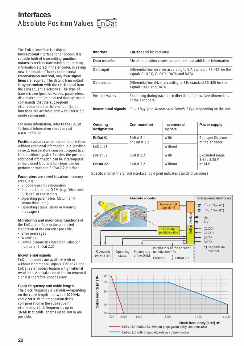
Interface EnDat serial bidirectional
Data transfer Absolute position values, parameters and additional information
Data input Differential line receiver according to EIA standard RS 485 for the signals CLOCK, CLOCK, DATA and DATA
Data output Differential line driver according to EIA standard RS 485 for the signals DATA and DATA
Position values Ascending during traverse in direction of arrow (see dimensions of the encoders)
Incremental signals » 1 VPP (see Incremental Signals 1 VPP) depending on the unit
The EnDat interface is a digital, bidirectional interface for encoders. It is capable both of transmitting position
values as well as transmitting or updating information stored in the encoder, or saving new information. Thanks to the serial
transmission method, only four signal
lines are required. The data is transmitted in synchronism with the clock signal from the subsequent electronics. The type of transmission (position values, parameters, diagnostics, etc.) is selected through mode commands that the subsequent electronics send to the encoder. Some functions are available only with EnDat 2.2 mode commands.
For more information, refer to the EnDat Technical Information sheet or visit www.endat.de.
Position values can be transmitted with or without additional information (e.g. position value 2, temperature sensors, diagnostics, limit position signals). Besides the position, additional information can be interrogated in the closed loop and functions can be performed with the EnDat 2.2 interface.
Parameters are saved in various memory areas, e.g.:
Encoder-specifi c information• Information of the OEM (e.g. “electronic • ID label” of the motor)Operating parameters (datum shift, • instructions, etc.)Operating status (alarm or warning • messages)
Monitoring and diagnostic functions of the EnDat interface make a detailed inspection of the encoder possible.
Error messages• Warnings• Online diagnostics based on valuation • numbers (EnDat 2.2)
Incremental signals
EnDat encoders are available with or without incremental signals. EnDat 21 and EnDat 22 encoders feature a high internal resolution. An evaluation of the incremental signal is therefore unnecessary.
Clock frequency and cable length
The clock frequency is variable—depending on the cable length—between 100 kHz and 2 MHz. With propagation-delay compensation in the subsequent electronics, clock frequencies up to 16 MHz at cable lengths up to 100 m are possible.
Ordering
designation
Command set Incremental
signals
Power supply
EnDat 01 EnDat 2.1 or EnDat 2.2
With See specifi cations of the encoder
EnDat 21 Without
EnDat 02 EnDat 2.2 With Expanded range3.6 to 5.25 V or 14 VEnDat 22 EnDat 2.2 Without
Specifi cation of the EnDat interface (bold print indicates standard versions)
Absolute encoder Subsequent electronics
Absolute position value En
Dat
inte
rfac
e
Incremental signals *)
» 1 VPP A*)
» 1 VPP B*)
Operating parameters
Operating status
Parameters of the OEM
Parameters of the encoder manufacturer for
EnDat 2.1 EnDat 2.2
*) Depends on encoder
Cab
le len
gth
[m
]
Clock frequency [kHz]EnDat 2.1; EnDat 2.2 without propagation-delay compensation
EnDat 2.2 with propagation-delay compensation
23
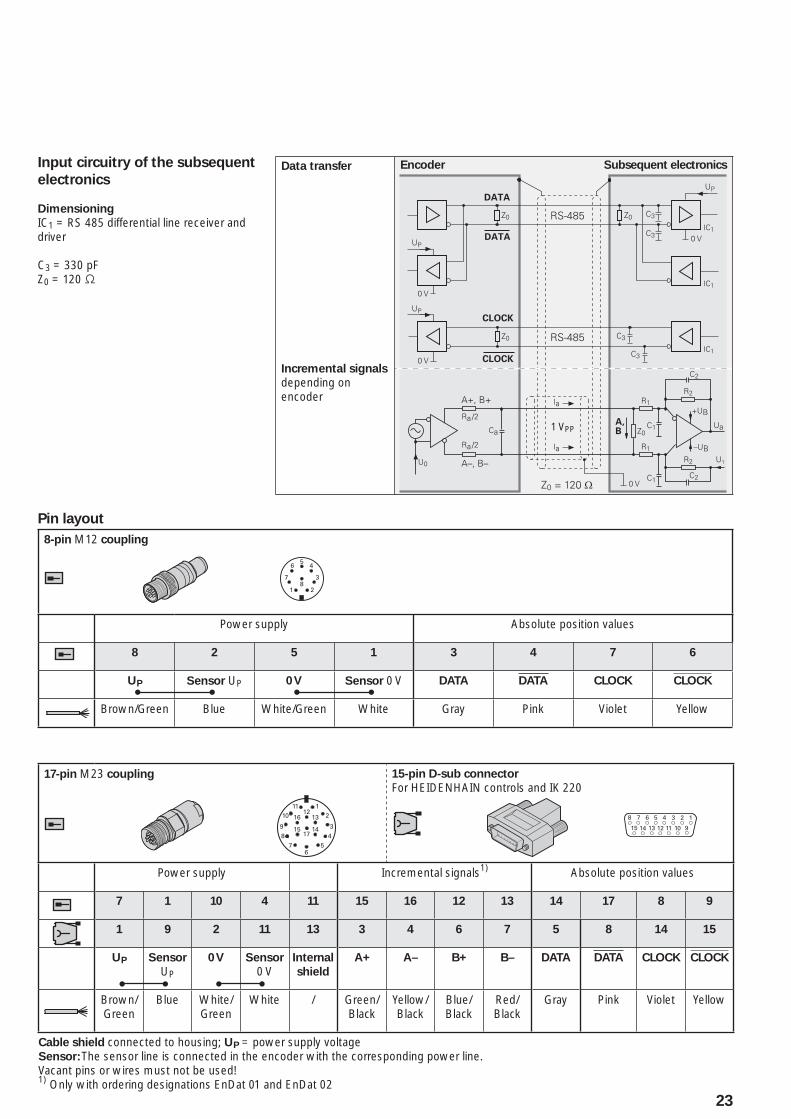
Pin layout
8-pin M12 coupling
Power supply Absolute position values
8 2 5 1 3 4 7 6
UP Sensor UP 0 V Sensor 0 V DATA DATA CLOCK CLOCK
Brown/Green Blue White/Green White Gray Pink Violet Yellow
17-pin M23 coupling 15-pin D-sub connector
For HEIDENHAIN controls and IK 220
Power supply Incremental signals1) Absolute position values
7 1 10 4 11 15 16 12 13 14 17 8 9
1 9 2 11 13 3 4 6 7 5 8 14 15
UP Sensor
UP
0 V Sensor
0 VInternal
shield
A+ A– B+ B– DATA DATA CLOCK CLOCK
Brown/Green
Blue White/Green
White / Green/Black
Yellow/Black
Blue/Black
Red/Black
Gray Pink Violet Yellow
Cable shield connected to housing; UP = power supply voltageSensor: The sensor line is connected in the encoder with the corresponding power line.Vacant pins or wires must not be used!1)
Only with ordering designations EnDat 01 and EnDat 02
Input circuitry of the subsequent
electronics
Dimensioning
IC1 = RS 485 differential line receiver and driver
C3 = 330 pFZ0 = 120 −
Data transfer
Incremental signals
depending on encoder
Encoder Subsequent electronics
1 VPP
M23
M23
M23
M23
M23
Cutout for mounting
M12
M12
24
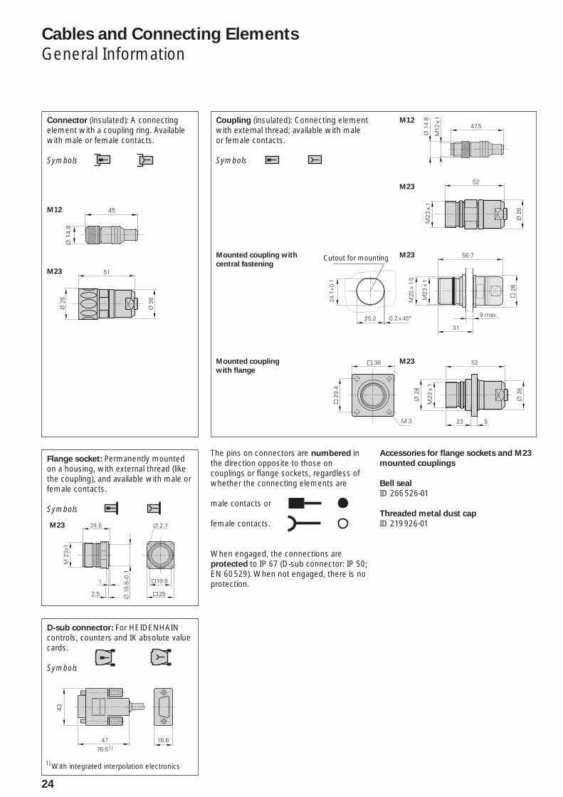
The pins on connectors are numbered in the direction opposite to those on couplings or fl ange sockets, regardless of whether the connecting elements are
male contacts or
female contacts.
When engaged, the connections are protected to IP 67 (D-sub connector: IP 50; EN 60 529). When not engaged, there is no protection.
Cables and Connecting Elements
General Information
Connector (insulated): A connecting element with a coupling ring. Available with male or female contacts.
Symbols
Coupling (insulated): Connecting element with external thread; available with male or female contacts.
Symbols
Accessories for fl ange sockets and M23
mounted couplings
Bell seal
ID 266 526-01
Threaded metal dust cap
ID 219 926-01
Flange socket: Permanently mounted on a housing, with external thread (like the coupling), and available with male or female contacts.
Symbols
Mounted coupling with
central fastening
Mounted coupling
with fl ange
1) With integrated interpolation electronics
D-sub connector: For HEIDENHAIN controls, counters and IK absolute value cards.
Symbols
25
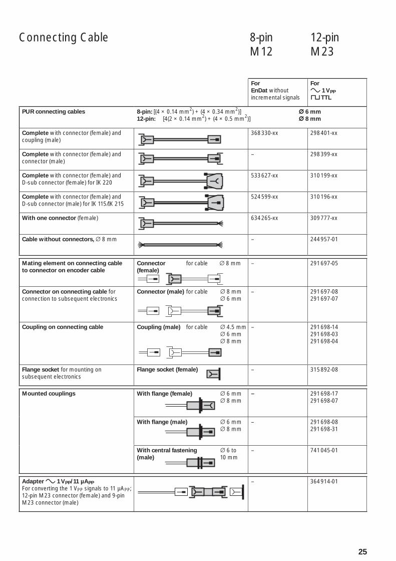
Connecting Cable 8-pin 12-pin M12 M23
For
EnDat without incremental signals
For
» 1 VPP
« TTL
PUR connecting cables 8-pin: [(4 × 0.14 mm2) + (4 × 0.34 mm2)] ¬ 6 mm
12-pin: [4(2 × 0.14 mm2) + (4 × 0.5 mm2)] ¬ 8 mm
Complete with connector (female) and coupling (male)
368 330-xx 298 401-xx
Complete with connector (female) and connector (male)
– 298 399-xx
Complete with connector (female) and D-sub connector (female) for IK 220
533 627-xx 310 199-xx
Complete with connector (female) and D-sub connector (male) for IK 115/IK 215
524 599-xx 310 196-xx
With one connector (female) 634 265-xx 309 777-xx
Cable without connectors, ¬ 8 mm – 244 957-01
Mating element on connecting cable
to connector on encoder cable
Connector for cable ¬ 8 mm(female)
– 291 697-05
Connector on connecting cable for connection to subsequent electronics
Connector (male) for cable ¬ 8 mm ¬ 6 mm
– 291 697-08291 697-07
Coupling on connecting cable Coupling (male) for cable ¬ 4.5 mm ¬ 6 mm ¬ 8 mm
– 291 698-14291 698-03291 698-04
Flange socket for mounting on subsequent electronics
Flange socket (female)
– 315 892-08
Mounted couplings With fl ange (female) ¬ 6 mm ¬ 8 mm
– 291 698-17291 698-07
With fl ange (male) ¬ 6 mm ¬ 8 mm
– 291 698-08291 698-31
With central fastening ¬ 6 to (male) 10 mm
– 741 045-01
Adapter » 1 VPP/11 µAPP
For converting the 1 VPP signals to 11 µAPP; 12-pin M23 connector (female) and 9-pin M23 connector (male)
– 364 914-01
26
General Electrical Information
Power supply
Connect HEIDENHAIN encoders only to subsequent electronics whose power supply is generated from PELV systems (EN 50 178). In addition, overcurrent protection and overvoltage protection are required in safety-related applications.
If HEIDENHAIN encoders are to be operated in accordance with IEC 61010-1, power must be supplied from a secondary circuit with current or power limitation as per IEC 61010-1:2001, section 9.3 or IEC 60950-1:2005, section 2.5 or a Class 2 secondary circuit as specifi ed in UL1310.
The encoders require a stabilized DC
voltage UP as power supply. The respective Specifi cations state the required power supply and the current consumption. The permissible ripple content of the DC voltage is:
High frequency interference• UPP < 250 mV with dU/dt > 5 V/µsLow frequency fundamental ripple• UPP < 100 mV
The values apply as measured at the encoder, i.e., without cable infl uences. The voltage can be monitored and adjusted with the encoder’s sensor lines. If a controllable power supply is not available, the voltage drop can be halved by switching the sensor lines parallel to the corresponding power lines.
Calculation of the voltage drop:
¹U = 2 · 10–3 ·
where ¹U: Voltage attenuation in V 1.05: Length factor due to twisted
wires LC: Cable length in m I: Current consumption in mA AP: Cross section of power lines in
mm2
The voltage actually applied to the encoder is to be considered when calculating the
encoder’s power requirement. This voltage consists of the supply voltage UP provided by the subsequent electronics minus the line drop at the encoder. For encoders with an expanded supply range, the voltage drop in the power lines must be calculated under consideration of the nonlinear current consumption (see next page).
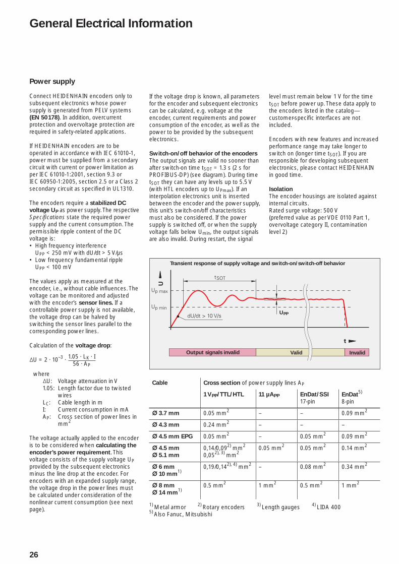
Transient response of supply voltage and switch-on/switch-off behavior
Output signals invalid InvalidValid
UPP
1.05 · LK · I56 · AP
Cable Cross section of power supply lines AP
1 VPP/TTL/HTL 11 µAPP EnDat/SSI
17-pinEnDat
5)
8-pin
¬ 3.7 mm 0.05 mm2 – – 0.09 mm2
¬ 4.3 mm 0.24 mm2 – – –
¬ 4.5 mm EPG 0.05 mm2 – 0.05 mm2 0.09 mm2
¬ 4.5 mm
¬ 5.1 mm
0,14/0,092) mm2
0,052), 3) mm20.05 mm2 0.05 mm2 0.14 mm2
¬ 6 mm
¬ 10 mm1)
0,19/0,142), 4) mm2 – 0.08 mm2 0.34 mm2
¬ 8 mm
¬ 14 mm1)
0.5 mm2 1 mm2 0.5 mm2 1 mm2
1) Metal armor 2) Rotary encoders 3) Length gauges 4) LIDA 4005) Also Fanuc, Mitsubishi
If the voltage drop is known, all parameters for the encoder and subsequent electronics can be calculated, e.g. voltage at the encoder, current requirements and power consumption of the encoder, as well as the power to be provided by the subsequent electronics.
Switch-on/off behavior of the encoders
The output signals are valid no sooner than after switch-on time tSOT = 1.3 s (2 s for PROFIBUS-DP) (see diagram). During time tSOT they can have any levels up to 5.5 V (with HTL encoders up to UPmax). If an interpolation electronics unit is inserted between the encoder and the power supply, this unit’s switch-on/off characteristics must also be considered. If the power supply is switched off, or when the supply voltage falls below Umin, the output signals are also invalid. During restart, the signal
level must remain below 1 V for the time tSOT before power up. These data apply to the encoders listed in the catalog—customer-specifi c interfaces are not included.
Encoders with new features and increased performance range may take longer to switch on (longer time tSOT). If you are responsible for developing subsequent electronics, please contact HEIDENHAIN in good time.
Isolation
The encoder housings are isolated against internal circuits.Rated surge voltage: 500 V(preferred value as per VDE 0110 Part 1, overvoltage category II, contamination level 2)
27
Encoders with expanded voltage
supply range
For encoders with expanded supply voltage range, the current consumption has a nonlinear relationship with the supply voltage. On the other hand, the power consumption follows a linear curve (see Current and power consumption diagram). The maximum power consumption at minimum and maximum supply voltage is listed in the Specifi cations. The power consumption at maximum supply voltage (worst case) accounts for:
Recommended receiver circuit• Cable length: 1 m• Age and temperature infl uences• Proper use of the encoder with respect • to clock frequency and cycle time
The typical current consumption at no load (only supply voltage is connected) for 5 V supply is specifi ed.
The actual power consumption of the encoder and the required power output of the subsequent electronics are measured while taking the voltage drop on the supply lines in four steps:
Step 1: Resistance of the supply lines
The resistance values of the power lines (adapter cable and encoder cable) can be calculated with the following formula:
RL = 2 ·
Step 2: Coeffi cients for calculation of
the drop in line voltage
b = –RL · – UP
c = PEmin · RL + · RL · (UP – UEmin)
Step 3: Voltage drop based on the
coeffi cients b and c
¹U = –0.5 · (b + ¹b2 – 4 · c)
Step 4: Parameters for subsequent
electronics and the encoder
Voltage at encoder:UE = UP – ¹U
Current requirement of encoder:IE = ¹U / RL
Power consumption of encoder:PE = UE · IE
Power output of subsequent electronics:PS = UP · IE
1.05 · LK · I56 · AP
Supply voltage [V]
Supply voltage [V]
Po
wer
ou
tpu
t o
f su
bseq
uen
t
ele
ctr
on
ics (
no
rmalized
)
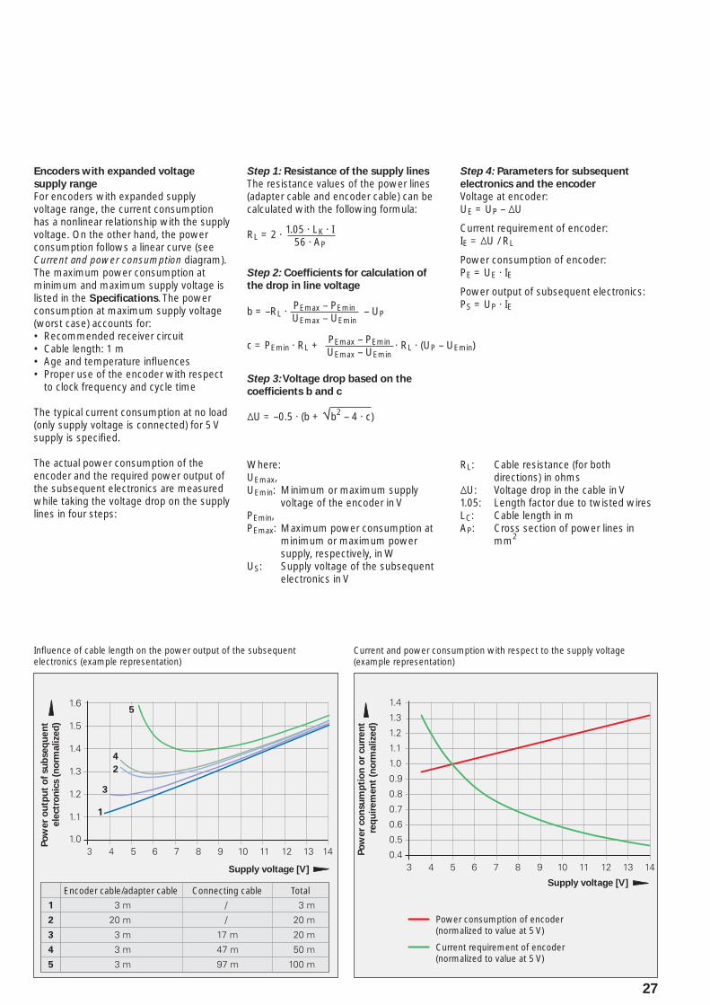
Encoder cable/adapter cable TotalConnecting cable
Po
wer
co
nsu
mp
tio
n o
r cu
rren
t
req
uir
em
en
t (n
orm
alized
)
Power consumption of encoder(normalized to value at 5 V)
Current requirement of encoder(normalized to value at 5 V)
Where:UEmax,UEmin: Minimum or maximum supply
voltage of the encoder in VPEmin,PEmax: Maximum power consumption at
minimum or maximum power supply, respectively, in W
US: Supply voltage of the subsequent electronics in V
RL: Cable resistance (for both directions) in ohms
¹U: Voltage drop in the cable in V1.05: Length factor due to twisted wiresLC: Cable length in mAP: Cross section of power lines in
mm2
Infl uence of cable length on the power output of the subsequent electronics (example representation)
Current and power consumption with respect to the supply voltage (example representation)
PEmax – PEminUEmax – UEmin
PEmax – PEminUEmax – UEmin
28
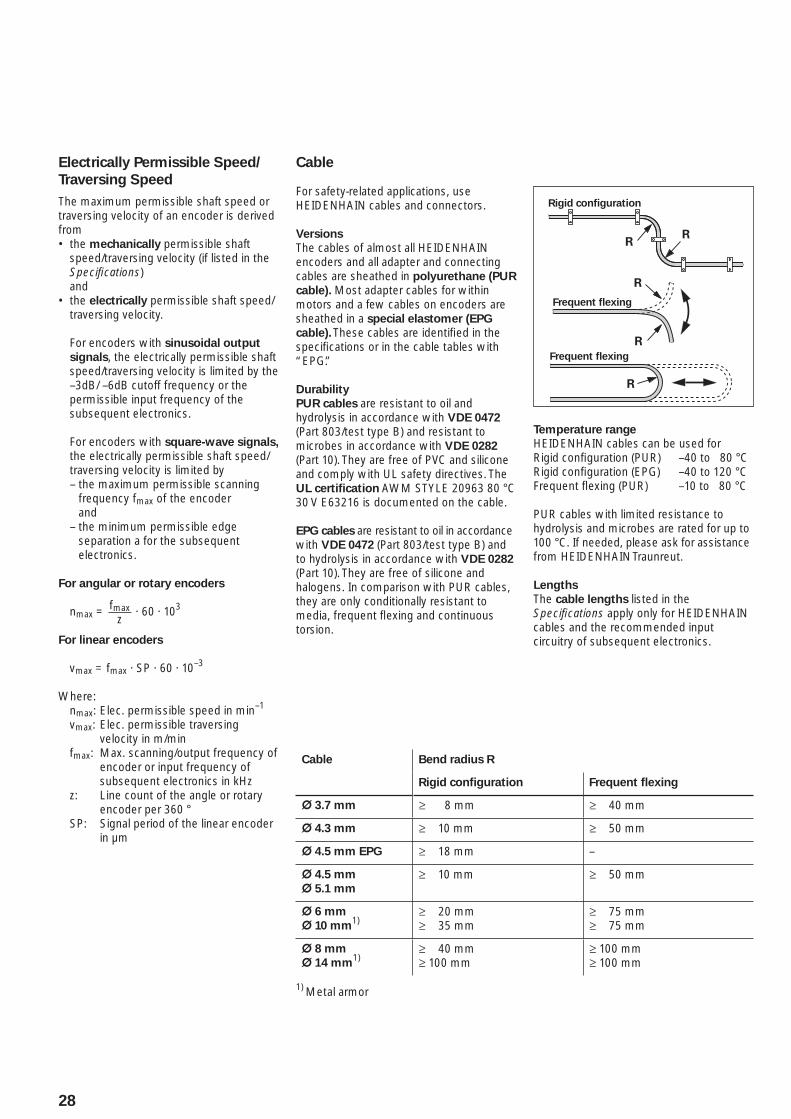
Rigid confi guration
Frequent fl exing
Frequent fl exing
Cable Bend radius R
Rigid confi guration Frequent fl exing
¬ 3.7 mm ‡ 8 mm ‡ 40 mm
¬ 4.3 mm ‡ 10 mm ‡ 50 mm
¬ 4.5 mm EPG ‡ 18 mm –
¬ 4.5 mm
¬ 5.1 mm
‡ 10 mm ‡ 50 mm
¬ 6 mm
¬ 10 mm1)
‡ 20 mm‡ 35 mm
‡ 75 mm‡ 75 mm
¬ 8 mm
¬ 14 mm1)
‡ 40 mm‡ 100 mm
‡ 100 mm‡ 100 mm
1) Metal armor
Cable
For safety-related applications, use HEIDENHAIN cables and connectors.
Versions
The cables of almost all HEIDENHAIN encoders and all adapter and connecting cables are sheathed in polyurethane (PUR
cable). Most adapter cables for within motors and a few cables on encoders are sheathed in a special elastomer (EPG
cable). These cables are identifi ed in the specifi cations or in the cable tables with “EPG.”
Durability
PUR cables are resistant to oil and hydrolysis in accordance with VDE 0472 (Part 803/test type B) and resistant to microbes in accordance with VDE 0282 (Part 10). They are free of PVC and silicone and comply with UL safety directives. The UL certifi cation AWM STYLE 20963 80 °C 30 V E63216 is documented on the cable.
EPG cables are resistant to oil in accordance with VDE 0472 (Part 803/test type B) and to hydrolysis in accordance with VDE 0282 (Part 10). They are free of silicone and halogens. In comparison with PUR cables, they are only conditionally resistant to media, frequent fl exing and continuous torsion.
Temperature range
HEIDENHAIN cables can be used forRigid confi guration (PUR) –40 to 80 °CRigid confi guration (EPG) –40 to 120 °CFrequent fl exing (PUR) –10 to 80 °C
PUR cables with limited resistance to hydrolysis and microbes are rated for up to 100 °C. If needed, please ask for assistance from HEIDENHAIN Traunreut.
Lengths
The cable lengths listed in the Specifi cations apply only for HEIDENHAIN cables and the recommended input circuitry of subsequent electronics.
Electrically Permissible Speed/
Traversing Speed
The maximum permissible shaft speed or traversing velocity of an encoder is derived from
the • mechanically permissible shaft speed/traversing velocity (if listed in the Specifi cations) andthe • electrically permissible shaft speed/traversing velocity.
For encoders with sinusoidal output
signals, the electrically permissible shaft speed/traversing velocity is limited by the –3dB/ –6dB cutoff frequency or the permissible input frequency of the subsequent electronics.
For encoders with square-wave signals, the electrically permissible shaft speed/ traversing velocity is limited by – the maximum permissible scanning
frequency fmax of the encoderand
– the minimum permissible edge separation a for the subsequent electronics.
For angular or rotary encoders
nmax = fmaxz
· 60 · 103
For linear encoders
vmax = fmax · SP · 60 · 10–3
Where: nmax: Elec. permissible speed in min–1
vmax: Elec. permissible traversing velocity in m/min
fmax: Max. scanning/output frequency of encoder or input frequency of subsequent electronics in kHz
z: Line count of the angle or rotary encoder per 360 °
SP: Signal period of the linear encoder in µm
29
Noise-Free Signal Transmission
Electromagnetic compatibility/
CE compliance
When properly installed, and when HEIDENHAIN connecting cables and cable assemblies are used, HEIDENHAIN encoders fulfi ll the requirements for electromagnetic compatibility according to 2004/108/EC with respect to the generic standards for:
Noise EN 61 000-6-2:•
Specifi cally: – ESD EN 61 000-4-2 – Electromagnetic fi elds EN 61 000-4-3 – Burst EN 61 000-4-4 – Surge EN 61 000-4-5 – Conducted
disturbances EN 61 000-4-6 – Power frequency
magnetic fi elds EN 61 000-4-8 – Pulse magnetic fi elds EN 61 000-4-9
Interference EN 61 000-6-4:•
Specifi cally: – For industrial, scientifi c and medical
equipment (ISM) EN 55 011 – For information technology
equipment EN 55 022
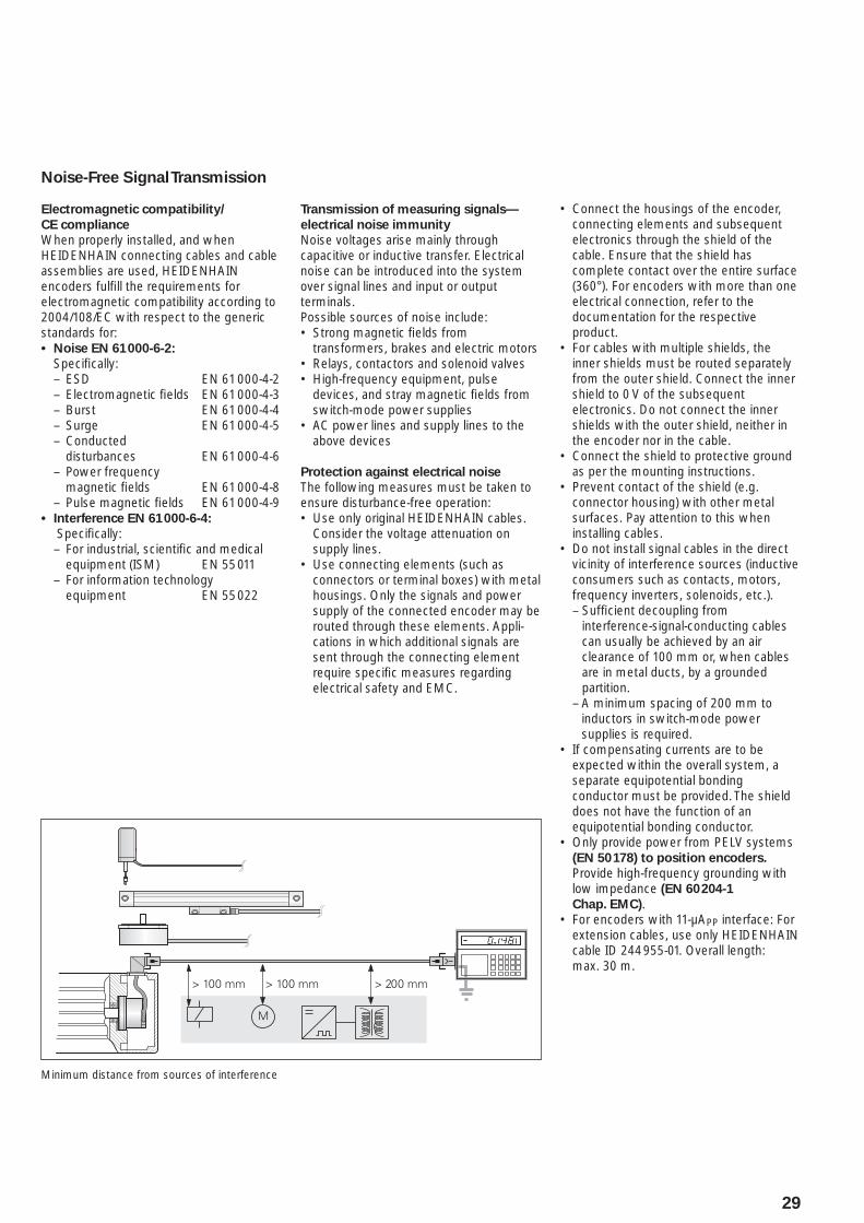
Connect the housings of the encoder, • connecting elements and subsequent electronics through the shield of the cable. Ensure that the shield has complete contact over the entire surface (360°). For encoders with more than one electrical connection, refer to the documentation for the respective product.For cables with multiple shields, the • inner shields must be routed separately from the outer shield. Connect the inner shield to 0 V of the subsequent electronics. Do not connect the inner shields with the outer shield, neither in the encoder nor in the cable.Connect the shield to protective ground • as per the mounting instructions.Prevent contact of the shield (e.g. • connector housing) with other metal surfaces. Pay attention to this when installing cables.Do not install signal cables in the direct • vicinity of interference sources (inductive consumers such as contacts, motors, frequency inverters, solenoids, etc.).– Suffi cient decoupling from
interference-signal-conducting cables can usually be achieved by an air clearance of 100 mm or, when cables are in metal ducts, by a grounded partition.
– A minimum spacing of 200 mm to inductors in switch-mode power supplies is required.
If compensating currents are to be • expected within the overall system, a separate equipotential bonding conductor must be provided. The shield does not have the function of an equipotential bonding conductor.Only provide power from PELV systems • (EN 50 178) to position encoders. Provide high-frequency grounding with low impedance (EN 60 204-1
Chap. EMC).For encoders with 11-µA• PP interface: For extension cables, use only HEIDENHAIN cable ID 244 955-01. Overall length: max. 30 m.
Transmission of measuring signals—
electrical noise immunity
Noise voltages arise mainly through capacitive or inductive transfer. Electrical noise can be introduced into the system over signal lines and input or output terminals.Possible sources of noise include:
Strong magnetic fi elds from • transformers, brakes and electric motorsRelays, contactors and solenoid valves• High-frequency equipment, pulse • devices, and stray magnetic fi elds from switch-mode power suppliesAC power lines and supply lines to the • above devices
Protection against electrical noise
The following measures must be taken to ensure disturbance-free operation:
Use only original HEIDENHAIN cables. • Consider the voltage attenuation on supply lines.Use connecting elements (such as • connectors or terminal boxes) with metal housings. Only the signals and power supply of the connected encoder may be routed through these elements. Appli-cations in which additional signals are sent through the connecting element require specifi c measures regarding electrical safety and EMC.
Minimum distance from sources of interference
30
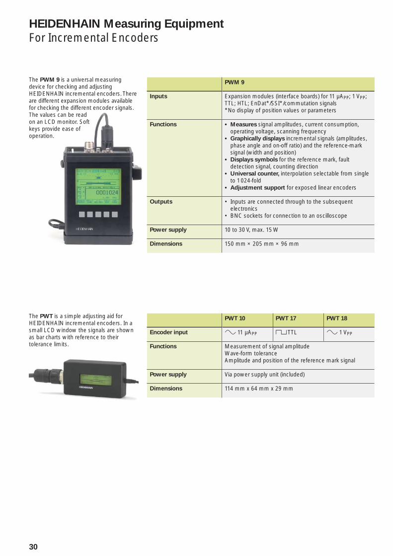
The PWM 9 is a universal measuring device for checking and adjusting HEIDENHAIN incremental encoders. There are different expansion modules available for checking the different encoder signals. The values can be read on an LCD monitor. Soft keys provide ease of operation.
PWM 9
Inputs Expansion modules (interface boards) for 11 µAPP; 1 VPP; TTL; HTL; EnDat*/SSI*/commutation signals*No display of position values or parameters
Functions Measures• signal amplitudes, current consumption, operating voltage, scanning frequencyGraphically displays• incremental signals (amplitudes, phase angle and on-off ratio) and the reference-mark signal (width and position)Displays symbols • for the reference mark, fault detection signal, counting directionUniversal counter,• interpolation selectable from single to 1 024-foldAdjustment support• for exposed linear encoders
Outputs Inputs are connected through to the subsequent • electronicsBNC sockets for connection to an oscilloscope•
Power supply 10 to 30 V, max. 15 W
Dimensions 150 mm × 205 mm × 96 mm
HEIDENHAIN Measuring Equipment
For Incremental Encoders
The PWT is a simple adjusting aid for HEIDENHAIN incremental encoders. In a small LCD window the signals are shown as bar charts with reference to their tolerance limits.
PWT 10 PWT 17 PWT 18
Encoder input » 11 µAPP « TTL » 1 VPP
Functions Measurement of signal amplitudeWave-form toleranceAmplitude and position of the reference mark signal
Power supply Via power supply unit (included)
Dimensions 114 mm x 64 mm x 29 mm
31
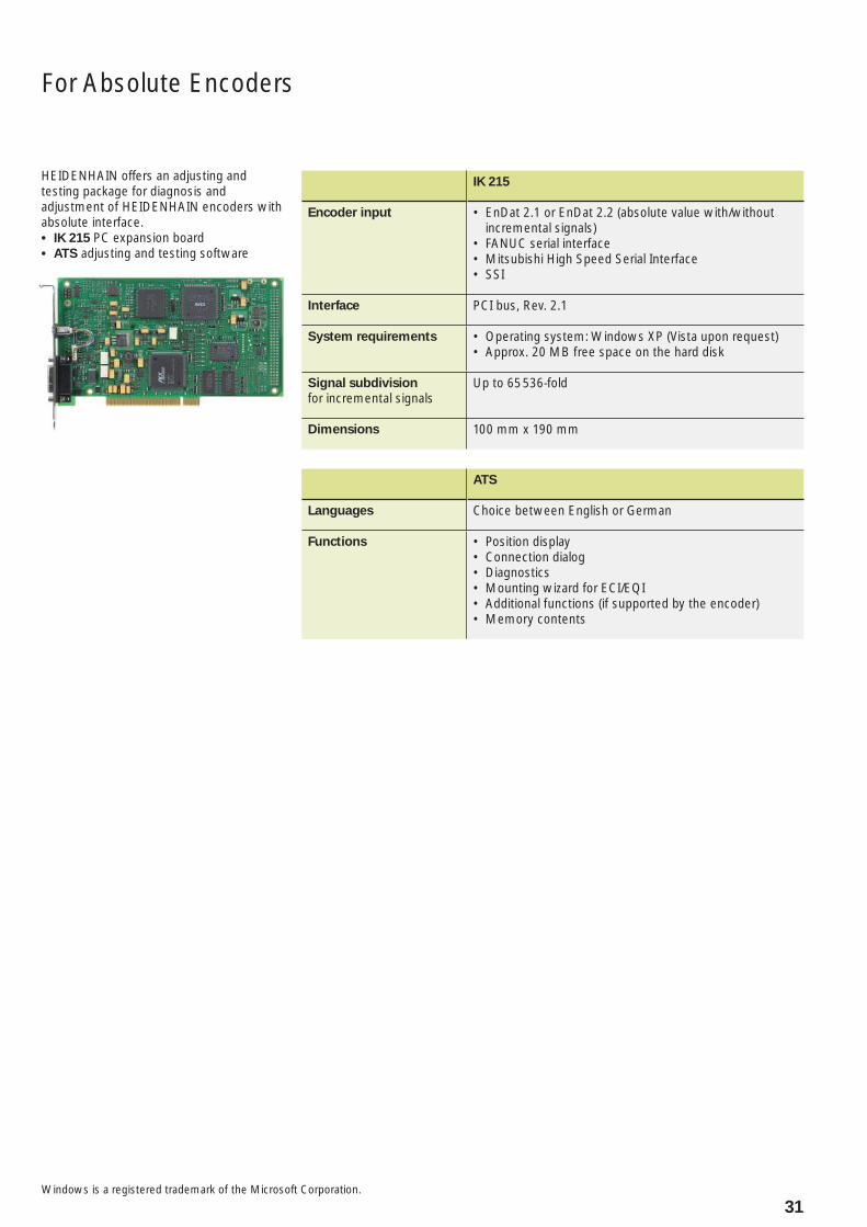
HEIDENHAIN offers an adjusting and testing package for diagnosis and adjustment of HEIDENHAIN encoders with absolute interface.
IK 215• PC expansion board ATS• adjusting and testing software
IK 215
Encoder input EnDat 2.1 or EnDat 2.2 (absolute value with/without • incremental signals)FANUC serial interface• Mitsubishi High Speed Serial Interface• SSI•
Interface PCI bus, Rev. 2.1
System requirements Operating system: Windows XP (Vista upon request)• Approx. 20 MB free space on the hard disk•
Signal subdivision
for incremental signalsUp to 65 536-fold
Dimensions 100 mm x 190 mm
ATS
Languages Choice between English or German
Functions Position display• Connection dialog• Diagnostics• Mounting wizard for ECI/EQI• Additional functions (if supported by the encoder)• Memory contents•
Windows is a registered trademark of the Microsoft Corporation.
For Absolute Encoders
PH Machinebanks` CorporationQuezon City, Philippines 1113E-mail: [email protected]
PL APS02-489 Warszawa, Polandwww.apserwis.com.pl
PT FARRESA ELECTRÓNICA, LDA.4470 - 177 Maia, Portugalwww.farresa.pt
RO HEIDENHAIN Reprezentanta RomaniaBrasov, 500338, Romaniawww.heidenhain.ro
RS Serbia − BG
RU OOO HEIDENHAIN125315 Moscow, Russiawww.heidenhain.ru
SE HEIDENHAIN Scandinavia AB12739 Skärholmen, Swedenwww.heidenhain.se
SG HEIDENHAIN PACIFIC PTE LTD.Singapore 408593www.heidenhain.com.sg
SK KOPRETINA TN s.r.o.91101 Trencin, Slovakiawww.kopretina.sk
SL Posredništvo HEIDENHAINNAVO d.o.o.2000 Maribor, Sloveniawww.heidenhain-hubl.si
TH HEIDENHAIN (THAILAND) LTDBangkok 10250, Thailandwww.heidenhain.co.th
TR T&M Mühendislik San. ve Tic. LTD. STI·.
34728 Ümraniye-Istanbul, Turkeywww.heidenhain.com.tr
TW HEIDENHAIN Co., Ltd.Taichung 40768, Taiwan R.O.C.www.heidenhain.com.tw
UA Gertner Service GmbH Büro Kiev 01133 Kiev, Ukrainewww.gertner.biz
US HEIDENHAIN CORPORATIONSchaumburg, IL 60173-5337, USAwww.heidenhain.com
VE Maquinaria Diekmann S.A. Caracas, 1040-A, VenezuelaE-mail: [email protected]
VN AMS Co. LtdHCM City, VietnamE-mail: [email protected]
ZA MAFEMA SALES SERVICES C.C.Midrand 1685, South Africawww.heidenhain.co.za
ES FARRESA ELECTRONICA S.A.08028 Barcelona, Spainwww.farresa.es
FI HEIDENHAIN Scandinavia AB02770 Espoo, Finlandwww.heidenhain.fi
FR HEIDENHAIN FRANCE sarl92310 Sèvres, Francewww.heidenhain.fr
GB HEIDENHAIN (G.B.) LimitedBurgess Hill RH15 9RD, United Kingdomwww.heidenhain.co.uk
GR MB Milionis Vassilis17341 Athens, Greecewww.heidenhain.gr
HK HEIDENHAIN LTDKowloon, Hong KongE-mail: [email protected]
HR Croatia − SL
HU HEIDENHAIN Kereskedelmi Képviselet1239 Budapest, Hungarywww.heidenhain.hu
ID PT Servitama Era ToolsindoJakarta 13930, IndonesiaE-mail: [email protected]
IL NEUMO VARGUS MARKETING LTD.Tel Aviv 61570, IsraelE-mail: [email protected]
IN HEIDENHAIN Optics & ElectronicsIndia Private LimitedChennai – 600 031, Indiawww.heidenhain.in
IT HEIDENHAIN ITALIANA S.r.l.20128 Milano, Italywww.heidenhain.it
JP HEIDENHAIN K.K.Tokyo 194-0215, Japanwww.heidenhain.co.jp
KR HEIDENHAIN Korea LTD.Gasan-Dong, Seoul, Korea 153-782www.heidenhain.co.kr
ME Montenegro − SL
MK Macedonia − BG
MX HEIDENHAIN CORPORATION MEXICO20235 Aguascalientes, Ags., MexicoE-mail: [email protected]
MY ISOSERVE Sdn. Bhd56100 Kuala Lumpur, MalaysiaE-mail: [email protected]
NL HEIDENHAIN NEDERLAND B.V.6716 BM Ede, Netherlandswww.heidenhain.nl
NO HEIDENHAIN Scandinavia AB7300 Orkanger, Norwaywww.heidenhain.no
AR NAKASE SRL.B1653AOX Villa Ballester, Argentinawww.heidenhain.com.ar
AT HEIDENHAIN Techn. Büro Österreich83301 Traunreut, Germanywww.heidenhain.de
AU FCR Motion Technology Pty. LtdLaverton North 3026, AustraliaE-mail: [email protected]
BA Bosnia and Herzegovina − SL
BE HEIDENHAIN NV/SA1760 Roosdaal, Belgiumwww.heidenhain.be
BG ESD Bulgaria Ltd.Sofi a 1172, Bulgariawww.esd.bg
BR DIADUR Indústria e Comércio Ltda.04763-070 – São Paulo – SP, Brazilwww.heidenhain.com.br
BY BelarusGERTNER Service GmbH50354 Huerth, Germanywww.gertner.biz
CA HEIDENHAIN CORPORATIONMississauga, OntarioL5T2N2, Canadawww.heidenhain.com
CH HEIDENHAIN (SCHWEIZ) AG8603 Schwerzenbach, Switzerlandwww.heidenhain.ch
CN DR. JOHANNES HEIDENHAIN (CHINA) Co., Ltd.Beijing 101312, Chinawww.heidenhain.com.cn
CZ HEIDENHAIN s.r.o.102 00 Praha 10, Czech Republicwww.heidenhain.cz
DK TP TEKNIK A/S2670 Greve, Denmarkwww.tp-gruppen.dk
DE HEIDENHAIN Technisches Büro Nord12681 Berlin, Deutschland{ 030 54705-240
HEIDENHAIN Technisches Büro Mitte08468 Heinsdorfergrund, Deutschland{ 03765 69544
HEIDENHAIN Technisches Büro West44379 Dortmund, Deutschland{ 0231 618083-0
HEIDENHAIN Technisches Büro Südwest70771 Leinfelden-Echterdingen, Deutschland{ 0711 993395-0
HEIDENHAIN Technisches Büro Südost83301 Traunreut, Deutschland{ 08669 31-1345
Vollständige und weitere Adressen siehe www.heidenhain.deFor complete and further addresses see www.heidenhain.de
Zu
m A
bh
eft
en
hie
r fa
lzen
! /
Fo
ld h
ere
fo
r fi
lin
g!
������������ ��� ��������������� ��������������������������������������� �������������� ������������������ ��!�"����������
������ !���� ��!�
745 168-21 · 10 · 9/2010 · F&W · Printed in Germany