Embed Size (px)
Citation preview
Modular IPS Machinery Arrangement in Early-Stage Naval Ship Design
David J. Jurkiewicz1 Carderock Division
Naval Surface Warfare Center West Bethesda, MD, USA
Julie Chalfant, Chrys Chryssostomidis Design Laboratory, Sea Grant College Program
Massachusetts Institute of Technology Cambridge, MA, USA
Abstract— Electrical power demands for naval surface combatants are projected to rise with the development of increasingly complex and power intensive combat systems. This trend coincides with the need to achieve maximum fuel efficiency at both high and low hull speeds. A proposed solution to meet current and future energy needs of conventionally powered naval surface combatants is through the use of an Integrated Power System (IPS), which is seen as the next evolution in naval ship design. In an effort to enhance the relationship between new-concept designs and historically-based ship design processes, this paper focuses on a novel approach of incorporating IPS at the earliest stage of the design process as part of assessing system-level tradeoffs early within the ship design process.
This paper describes a methodology for the systematic design and arrangement of an IPS machinery plant to meet a desired power generation level. In conjunction with the methodology development, a hierarchical process and design tool were produced to assist in rapid development and evaluation of various IPS arrangements. The result of this process, through several case studies, provides insight into equipment selection philosophy, the initial sizing of the ship’s machinery box, and the initial definition of electrical zones.
I. INTRODUCTION This paper explores a new design process, rooted in
principles of naval architecture, marine engineering, and mechanical engineering, and applies it to new-concept ship designs. The focus of the application is on both current and future Integrated Power System (IPS) power generation and propulsion architectures. A methodology is proposed to present new insights into the historical ship design process while meeting the requirements of new-concept ship designs. The primary research objective was to implement the methodology by constructing an IPS design tool, the IPS Design Module (IPSDM), to aid the ship designer in systematically selecting and arranging IPS architectures at the start of the ship design process.
IPS incorporates power generation, propulsion, and ship service distribution into a single integrated system. The shift to IPS is driven by the significantly increased power requirements of future weapon and sensor systems. It is also driven by the need to increase ship affordability, mission performance, and operability [1]. In addition, IPS allows somewhat greater architectural flexibility in the ship design since it is not necessary to align the propeller shaft with the prime movers. Instead, propulsion motors are coupled to the propeller shaft, allowing the ship designer to position the prime movers in other areas of the ship. This enhancement permits the designer to increase ship survivability through separation and distribution [1].
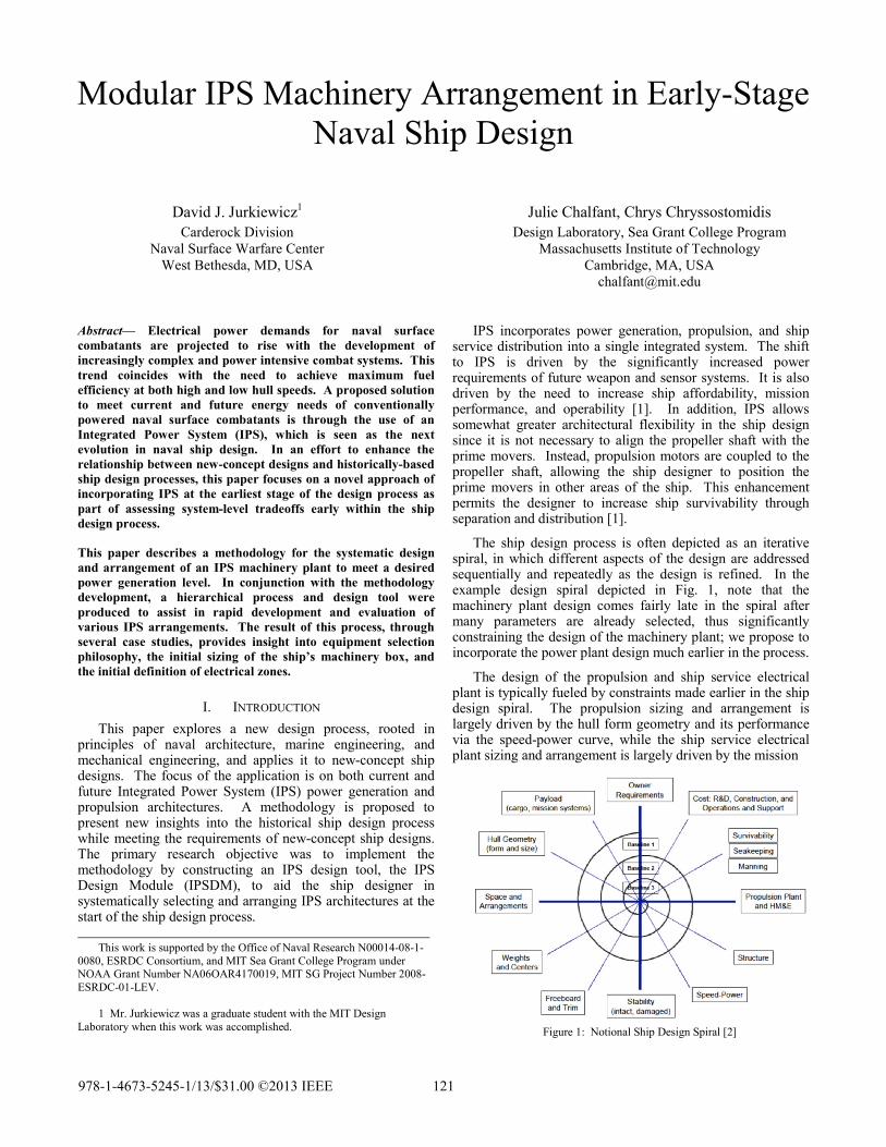
The ship design process is often depicted as an iterative spiral, in which different aspects of the design are addressed sequentially and repeatedly as the design is refined. In the example design spiral depicted in Fig. 1, note that the machinery plant design comes fairly late in the spiral after many parameters are already selected, thus significantly constraining the design of the machinery plant; we propose to incorporate the power plant design much earlier in the process.
The design of the propulsion and ship service electrical plant is typically fueled by constraints made earlier in the ship design spiral. The propulsion sizing and arrangement is largely driven by the hull form geometry and its performance via the speed-power curve, while the ship service electrical plant sizing and arrangement is largely driven by the mission
Figure 1: Notional Ship Design Spiral [2]
This work is supported by the Office of Naval Research N00014-08-1-0080, ESRDC Consortium, and MIT Sea Grant College Program under NOAA Grant Number NA06OAR4170019, MIT SG Project Number 2008-ESRDC-01-LEV.
1 Mr. Jurkiewicz was a graduate student with the MIT Design
Laboratory when this work was accomplished.
978-1-4673-5245-1/13/$31.00 ©2013 IEEE 121
Report Documentation Page Form ApprovedOMB No. 0704-0188
Public reporting burden for the collection of information is estimated to average 1 hour per response, including the time for reviewing instructions, searching existing data sources, gathering andmaintaining the data needed, and completing and reviewing the collection of information. Send comments regarding this burden estimate or any other aspect of this collection of information,including suggestions for reducing this burden, to Washington Headquarters Services, Directorate for Information Operations and Reports, 1215 Jefferson Davis Highway, Suite 1204, ArlingtonVA 22202-4302. Respondents should be aware that notwithstanding any other provision of law, no person shall be subject to a penalty for failing to comply with a collection of information if itdoes not display a currently valid OMB control number.
1. REPORT DATE APR 2013
2. REPORT TYPE N/A
3. DATES COVERED -
4. TITLE AND SUBTITLE Modular IPS Machinery Arrangement in Early-Stage Naval Ship Design
5a. CONTRACT NUMBER
5b. GRANT NUMBER
5c. PROGRAM ELEMENT NUMBER
6. AUTHOR(S) 5d. PROJECT NUMBER
5e. TASK NUMBER
5f. WORK UNIT NUMBER
7. PERFORMING ORGANIZATION NAME(S) AND ADDRESS(ES) Carderock Division Naval Surface Warfare Center West Bethesda, MD, USA
8. PERFORMING ORGANIZATIONREPORT NUMBER
9. SPONSORING/MONITORING AGENCY NAME(S) AND ADDRESS(ES) 10. SPONSOR/MONITOR’S ACRONYM(S)
11. SPONSOR/MONITOR’S REPORT NUMBER(S)
12. DISTRIBUTION/AVAILABILITY STATEMENT Approved for public release, distribution unlimited
13. SUPPLEMENTARY NOTES See also ADA581781. IEEE Electric Ship Technologies Symposium (IEEE ESTS 2013) Held in Arlington,Virginia on April 22-24, 2013. U.S. Government or Federal Purpose Rights License.
14. ABSTRACT Electrical power demands for naval surface combatants are projected to rise with the development ofincreasingly complex and power intensive combat systems. This trend coincides with the need to achievemaximum fuel efficiency at both high and low hull speeds. A proposed solution to meet current and futureenergy needs of conventionally powered naval surface combatants is through the use of an IntegratedPower System (IPS), which is seen as the next evolution in naval ship design. In an effort to enhance therelationship between new-concept designs and historically-based ship design processes, this paper focuseson a novel approach of incorporating IPS at the earliest stage of the design process as part of assessingsystem-level tradeoffs early within the ship design process. This paper describes a methodology for thesystematic design and arrangement of an IPS machinery plant to meet a desired power generation level. Inconjunction with the methodology development, a hierarchical process and design tool were produced toassist in rapid development and evaluation of various IPS arrangements. The result of this process,through several case studies, provides insight into equipment selection philosophy, the initial sizing of theships machinery box, and the initial definition of electrical zones.
15. SUBJECT TERMS
16. SECURITY CLASSIFICATION OF: 17. LIMITATION OF ABSTRACT
SAR
18. NUMBEROF PAGES
7
19a. NAME OFRESPONSIBLE PERSON
a. REPORT unclassified
b. ABSTRACT unclassified
c. THIS PAGE unclassified

Standard Form 298 (Rev. 8-98) Prescribed by ANSI Std Z39-18

system electrical loads. The methodology described herein redefines the inputs and outputs of the typical ship design process utilizing IPS. It also highlights the overall assumptions inherent in the process and the establishment of a hierarchy of equipment required during the machinery arrangement process.
By addressing the energy requirement early in the ship design process, the ship design can in part revolve around the energy capability of the ship to meet energy demands of the customer requirements. This approach alters the interdependences between the design elements in the process, linking them to the independent variables of both mission and energy systems. In essence, the foundation of the baseline design is determined by the tradeoffs between energy systems, mission systems, and customer requirements.
II. THE IPS DESIGN MODULE (IPSDM) The IPS Design Module (IPSDM) is a software tool that
provides a structured procedure focused on the selection and arrangement of shipboard electrical generation and distribution system equipment for an integrated power system which, by definition, services both propulsion and ship service power needs. In this paper, we summarize the major elements of IPSDM and the methods IPSDM uses to addresses power generation, propulsion, distribution, thermal management, and arrangement. A more thorough description and a detailed user’s manual can be found in [3]. The major elements within IPSDM are identified as follows; each is described in more detail in this section.
A. Planning B. Equipment Selection C. Electrical Load Analysis D. Zonal Electrical Distribution Selection E. Machinery Arrangement F. Thermal Load Analysis G. Weight Estimation H. Output
A. Planning In order to effectively incorporate the assumptions of the
IPS design process, planning is required before making any equipment selections. Two critical areas of planning exist: determination of the power requirement and determination of the number and types of compartments devoted to IPS equipment. The power requirement is the most critical input to the process forming the basis for all equipment selection and subsequent analysis, determining quantity and compartments sizes of the IPS architecture.
1) Power requirement. The power requirement is the total maximum power
estimate for a particular ship design. It is the sum of estimated propulsion power required for the ship to achieve a maximum speed and the estimated maximum electrical load required for ship service operations. To this we must add the IPS auxiliary electrical loads and the distribution losses. Inherent in this calculation is the decision of whether the ship will carry enough installed power to simultaneously supply full propulsion power and full ship service electrical power; an
integrated power system allows this tradeoff decision. The propulsion and ship service electrical values form the basis for all design decisions with regard to power generation equipment and propulsion motor selection. The overall power requirement can be estimated using:
• Previous ship design power usage • A selected number and type of generators to be installed • A particular hull form with a specified payload plus a
factor for services • An iterative process in which various stages of design
data are available at each iteration
The designer must understand the basis of the power requirement to make effective IPS design decisions later in the IPS design process. Applying design margins and service life allowances for the estimated power capacity can also be determined at this stage if the power requirement is largely uncertain.
2) Number and types of compartments. Planning the number and types of compartments for the
machinery equipment is important before selecting any equipment item. The number of compartments establishes one of the upper elements of the machinery arrangement hierarchy, and essentially allocates the space early in the process where the equipment will eventually reside in the ship. The number of compartments also will form the basis of identifying electrical zones later in the process.
We define three types of compartments as follows:
Main Machinery Room (MMR): a compartment that contains equipment intended for ship propulsion such as large PGMs and PMMs. This compartment may also contain other auxiliary components such as distilling plants.
Auxiliary Machinery Room (AMR): a compartment that contains equipment for support of ship service electrical power and any additional support equipment
Other Machinery Room (OMR): a machinery compartment that is separate from the MMR and AMR consecutive stack-up configuration, thus allowing user-specified separation between the consecutive machinery compartments.
B. Equipment Selection In order to effectively select and arrange the equipment at
a meaningful level of fidelity, we decomposed IPS into three main areas: Power Generation (consisting of the prime mover and generator), Propulsion (consisting of the motor), and Distribution (consisting of conversion, transmission and cooling equipment). Each of the major pieces of equipment have auxiliary support equipment, e.g. lube oil service, cooling, or controls, associated with them. This auxiliary support equipment is required for the major piece of equipment to operate, but it constitutes an additional load, which is accounted for within the IPSDM.
1) Power Generation Module (PGM) The first step in equipment selection is to choose a suitable
combination of power generation modules (PGMs) to meet the desired total power requirement. Examples of design
122

philosophies that influence PGM selection to achieve the power requirement include but are not limited to:
• Increased power density: choose large or power-dense prime movers, potentially also achieving economy of scale with respect to auxiliaries, intake/uptake volume, etc.
• Increased flexibility and redundancy: many smaller PGMs improve redundancy and survivability; however, this will most likely require more space and weight
• Minimize fuel consumption: choose PGM power levels for ideal loading at typical operating states
• Maximize commonality: Choose a common set of PGMs to reduce spare parts and specialized operational and training requirements
2) Propulsion Motor Module (PMM) The PMM selection can be based on either 1) the required
propulsion power value from an estimated hullform, or 2) an initial estimate of propulsion power achieved by assigning a propulsion percentage factor (PPF) to the total power requirement. A PPF is an assumed percentage of the total power designated for propulsion only, with the remainder allocated to ship service electrical demand.
For the initial design cycle without a hull form selected or known propulsion power requirement, it is recommended that a PPF be applied to the total power requirement. This assumption should be applied to new-concept designs at the start of the design cycle, and may change as the ship design increases in fidelity in additional cycles. Since IPS is assumed to be a fully integrated system, power from other PGMs not intended for propulsion loads at certain power profiles may be partially drawn into the propulsion system. Applying a PPF to the total power requirement initially allocates a defined power level for propulsion for a desired maximum speed as a percentage of the sum of PGM outputs. Therefore, when a hull geometry is eventually selected, hull resistance estimates at a particular speed can be compared to the allocated propulsion power level, allowing the designer to trade off speed and power early in the design process. The remaining power is assumed to be used for ship service electrical loads.
Once a propulsion power requirement is established, PMM modules are selected to meet the desired propulsion power requirement. A disadvantage of electric propulsion is the transmission efficiency. Overall efficiencies of electric propulsion drive trains are in the neighborhood of 89%, much lower than the 95% seen by traditional mechanical propulsion drive trains. An advantage of electric propulsion is that propulsion and electrical service loads can be combined on fewer generators to achieve improved loading and thus improved efficiency.
3) Additional Auxiliary Systems The majority of the auxiliary systems within the IPSDM
cascade from the PGM and PMM selections; however, additional auxiliary systems may be required for compartment and zonal systems. We include in the IPSDM the cooling and firemain systems because they are assumed to interface with the hull in the machinery compartments. The placement of this auxiliary equipment will influence the location of other
equipment within the compartment, especially for access and removal. Although IPSDM does not design the entire cooling and firemain systems, it does allow the designer to allocate space and power within the machinery spaces for pumps, strainers, sea chests and related equipment that will interface with each of the distributed systems.
C. Electrical Load Analysis Once the equipment selections have been made, an
electrical load analysis of the IPS auxiliary equipment can be conducted on all equipment within the IPS that requires electrical power, e.g. the fuel service systems, lube oil systems, and start air systems. Within IPSDM, we assume the load to be the maximum continuous rating of the equipment. This allows the use of the methodology in DDS 310-1 [4] for estimating the total electrical load of the auxiliaries through the use of typical operating load factors. The total electrical load of associated auxiliary equipment is subtracted from the total power provided by the PGMs to provide a value for net power available to be used for propulsion and ship service electrical loads.
D. Zonal Electrical Distribution Selection Without the electrical distribution system, power
management for propulsion and ship service electrical loads could not be integrated. IPSDM allows the designer to select the desired architecture and tailor it to the equipment selections made earlier in the IPSDM design process. It also allows the designer to define electrical zones based on the number of machinery compartments as a basis. The zonal definition can be expanded after defining mission systems and ship geometry, but IPSDM starts the zonal definition process. The following five items of information generated within IPSDM are used to determine of the initial number of electrical zones:
1. Number and type of machinery compartments 2. Total distributable power and location of generators 3. Propulsion motor load 4. Estimate of ship service electrical power and locations 5. Auxiliary equipment loads and locations
While determining zonal definition of the ship, choices in AC or DC voltage distribution can be assessed and selected. The number of zones and type of voltage determinations play a role in determining the number and types of converters required. Each zone may require multiple rectifiers, converters, and inverters to satisfy the zonal power requirements.
E. Machinery Arrangement Once all of the equipment selections have been satisfied,
the final step in IPSDM is to arrange the equipment. The arrangement of equipment is the largest portion of the IPS design process, and is the most time intensive portion, especially during a clean-sheet design. This section highlights important guidelines and philosophies collected from historical design data sheets, discussions with experts in the field, and texts on the subject of marine engineering.
123

1) Equipment Arrangement Philosophy. Arranging equipment in a compartment is similar to
constructing a three-dimensional puzzle. Pieces must be located in specific areas of the ship in order to maximize operational efficiency and ship recoverability while minimizing total volume. Spacing and positing equipment for manned access is critical for maintenance, construction, and operation. It is the driver behind the arrangement of equipment within a space. The following list forms the basis of the machinery arrangement philosophy and is largely derived from Design of Propulsion and Electric Power Generation Systems [5].
• The propulsion motor is located such that it can be connected to the propulsors.
• Auxiliary equipment is located in the direct vicinity of the main equipment it supports, thus reducing piping, cabling, and vulnerability.
• Liquid-handling equipment such as fuel and lube oil service equipment and saltwater pumps should be located low within the machinery spaces to minimize piping and head losses.
• Electronic equipment should be located high in the machinery compartment to avoid failure due to equipment leaks or flooding in the space.
• Sufficient access space should be provided for control, monitoring, and maintenance of machinery and electrical equipment. Typical widths for passageways within the machinery spaces are 3-4 feet for access [6].
• Prime movers should be located fore and aft, not athwartships, to avoid performance problems as the ship rolls.
2) IPSDM Arrangement Procedure The IPSDM arrangement process is divided into three
steps: equipment location, compartment definition, and stack-up definition.
a) Equipment location The equipment selected earlier must be allocated to
compartments and arranged. In order to use the IPSDM machinery arrangement process effectively, the following additional machinery arrangement guidelines are provided:
• Locate the prime movers, generators, and propulsion motors first within a compartment due to their large size and many auxiliaries.
• Position the end of the prime mover with the air ducting in close proximity to a compartment bulkhead to minimize ducting impacts to the spaces above the machinery space. Should another prime mover be located in an adjacent compartment, align the prime movers in adjacent spaces so they share a common bulkhead to minimize ducting impacts. Minimize elbows of intakes to gas turbines to reduce head losses.
• Assume large generators and propulsion motors are life-of-ship parts, unless otherwise known. This assumption reduces required space forward of the generator for maintenance.
• When placing propulsion motors, be aware of propeller diameter and shaft depression angle constraints.
• Cluster electronic equipment within a machinery space to reduce deck area and cable runs, but provide sufficient separation to accommodate cable bending radii.
b) Compartment definition The overall dimensions of the compartments are
determined individually based on the dimensions of equipment placed in the compartment while maintaining clearance for operations and maintenance access.
c) Stack-up definition The third level combines the compartments into a single
machinery block, defining the machinery bulkheads for the ship. Within IPSDM, the designer can easily adjust the sequence of compartments within the stack-up configuration. OMRs, if required by the IPS design, are not included in the stack-up definition because they are independently placed in the ship later in the design process.
Survivability considerations may require the inclusion of additional compartments not necessitated by the equipment selection. For example, compartments may be required to separate main machinery rooms in case of flooding, even if the compartments are not required specifically for placing equipment. The lengths of the additional compartments are defined by the designer, and can be determined using naval standards or assessments from a floodable length or other damaged stability analysis.
F. Thermal Load Estimation With the power generation, propulsion, auxiliary, and
distribution equipment selected, IPSDM performs a thermal load estimation. The thermal load of IPS equipment can be computed based on equipment efficiency and the electrical load profile.
In an effort to estimate the thermal loads of the IPS architecture, DDS 310-1 was applied in conjunction with assumed equipment efficiencies.
The output of this process yields the total thermal load of each compartment, each electrical zone, and the sum of the compartments yields the total thermal load of the selected equipment for IPS; however, the thermal load estimation process does not identify the cooling media or the design of a thermal management system. Other specialized design tools such as the MIT-developed Cooling System Design Tool [7], can take advantage of thermal load analysis output for the construction of a thermal management system in conjunction with the mission system thermal load.
G. Weight Estimation The weight of each piece of equipment is stored within the
equipment database, so the weight estimation procedure within IPSDM simply sums the weight of the equipment. It then automatically divides the weights into separate accounting weight groups using the US Navy’s Expanded Ship Work Breakdown Structure (ESWBS) [8]. The IPSDM procedure estimates weight groups 200 (Propulsion), 300 (Electrical), and 500 (Auxiliary). A few items within those groups require the machinery block to be placed within the ship hull in order to determine their weight; thus, weights for
124
intake and exhaust ducting, propeller shafts, propellers and cabling are not estimated.
H. Output Once all power requirements, equipment selections, and
arrangements are complete, the following data is calculated and stored in the database for use in further design of the ship:
• Total installed brake power and distributable power • Total required propulsion power • Total auxiliary power at maximum demand • Thermal load of machinery systems • Margins and allowances • Machinery compartment names, overall dimensions
(length, width, and height), volumetric centroids about the origin (0,0,0), and associated bulkhead locations, decks, and deck heights
• Propeller diameter and maximum RPM • Exhaust and intake diameters and location • The entire list of selected equipment, each with:
• Overall dimensions (length, width, and height) • Equipment volumetric centroid (relative to each
compartment’s centroid) • Weight • Location (identifies compartment) • ESWBS classification
III. CASE STUDY The IPSDM process was applied to a clean-sheet medium-
sized surface combatant design to demonstrate the ability to perform system-level tradeoffs independent of hull geometry. Using this process, we generated two IPS machinery plants: the first is similar to a DDG-51 but with increased power requirements, while the second attempted to minimize stack-up length while maintaining an equivalent energy capability. We then quantified the space, weight, and thermal impacts of each design. As a final step, we rearranged the first design to reduce beam. The following conditions were assumed:
• propulsion demand of 75-84 MW • 84 MW for variant 1 • 75 MW for variant 2 due to the efficiencies of
the contra-rotating propeller design • ship service electrical demand of 7 MW • gas turbine generators used for power generation • one additional auxiliary PGM included to satisfy the N+1
criterion • ac distribution for propulsion, dc distribution for ship’s
electrical service • port and starboard electrical buses with four total zones
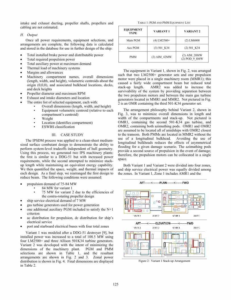
Variant 1 was modeled after a DDG-51 destroyer [9], but installed power was increased to a total of 108.5 MW using four LM2500+ and three Allison 501K34 turbine generators. Variant 2 was developed with the intent of minimizing the dimensions of the machinery plant. PGM and PMM selections are shown in Table 1, and the resultant arrangements are shown in Fig. 2 and 3. Zonal power distribution is shown in Fig. 4. Final dimensions are displayed in Table 2.
The equipment in Variant 1, shown in Fig. 2, was arranged
such that two LM2500+ generator sets and one propulsion motor were placed in a single machinery room (MMR1); this caused a fairly wide compartment beam but reduced total stack-up length. AMR2 was added to increase the survivability of the system by providing separation between the two propulsion motors and between the main gas turbine generators located in MMR1 and MMR2. Not pictured in Fig. 2 is an OMR containing the third 501-K34 generator set.
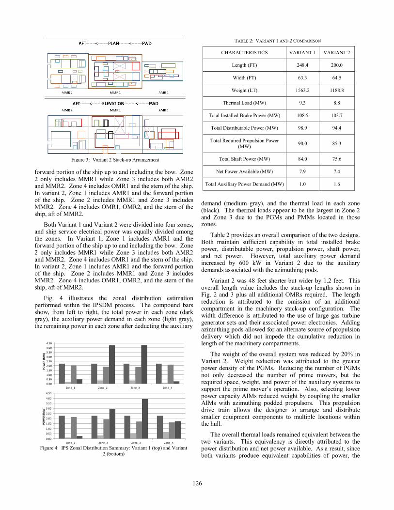
The arrangement philosophy behind Variant 2, shown in Fig. 3, was to minimize overall dimensions in length and width of the compartments and stack-up. Not pictured is OMR1, containing the second 501-K34 gas turbine, and OMR2, containing both azimuthing pods. OMR1 and OMR2 are assumed to be located aft of amidships with OMR2 closest to the transom. Both PMMs are located in MMR2 without the use of a longitudinal bulkhead. Avoiding the use of longitudinal bulkheads reduces the effects of asymmetrical flooding for a given damage scenario. The azimuthing pods provide a second source of propulsion in the event of damage; therefore, the propulsion motors can be collocated in a single space.
Both Variant 1 and Variant 2 were divided into four zones, and ship service electrical power was equally divided among the zones. In Variant 1, Zone 1 includes AMR1 and the
Figure 2: Variant 1 Stack-up Arrangement
TABLE 1: PGM AND PMM EQUIPMENT LIST
EQUIPMENT TYPE VARIANT 1 VARIANT 2
Main PGM (4) LM2500+ (2) LM6000
Aux PGM (3) 501_K34 (2) 501_K34
PMM (2) AIM_42MW (2) AIM_28MW (2) POD_9_8MW
125
forward portion of the ship up to and including the bow. Zone 2 only includes MMR1 while Zone 3 includes both AMR2 and MMR2. Zone 4 includes OMR1 and the stern of the ship. In variant 2, Zone 1 includes AMR1 and the forward portion of the ship. Zone 2 includes MMR1 and Zone 3 includes MMR2. Zone 4 includes OMR1, OMR2, and the stern of the ship, aft of MMR2.
Both Variant 1 and Variant 2 were divided into four zones, and ship service electrical power was equally divided among the zones. In Variant 1, Zone 1 includes AMR1 and the forward portion of the ship up to and including the bow. Zone 2 only includes MMR1 while Zone 3 includes both AMR2 and MMR2. Zone 4 includes OMR1 and the stern of the ship. In variant 2, Zone 1 includes AMR1 and the forward portion of the ship. Zone 2 includes MMR1 and Zone 3 includes MMR2. Zone 4 includes OMR1, OMR2, and the stern of the ship, aft of MMR2.
Fig. 4 illustrates the zonal distribution estimation performed within the IPSDM process. The compound bars show, from left to right, the total power in each zone (dark gray), the auxiliary power demand in each zone (light gray), the remaining power in each zone after deducting the auxiliary
demand (medium gray), and the thermal load in each zone (black). The thermal loads appear to be the largest in Zone 2 and Zone 3 due to the PGMs and PMMs located in those zones.
Table 2 provides an overall comparison of the two designs. Both maintain sufficient capability in total installed brake power, distributable power, propulsion power, shaft power, and net power. However, total auxiliary power demand increased by 600 kW in Variant 2 due to the auxiliary demands associated with the azimuthing pods.
Variant 2 was 48 feet shorter but wider by 1.2 feet. This overall length value includes the stack-up lengths shown in Fig. 2 and 3 plus all additional OMRs required. The length reduction is attributed to the omission of an additional compartment in the machinery stack-up configuration. The width difference is attributed to the use of large gas turbine generator sets and their associated power electronics. Adding azimuthing pods allowed for an alternate source of propulsion delivery which did not impede the cumulative reduction in length of the machinery compartments.
The weight of the overall system was reduced by 20% in Variant 2. Weight reduction was attributed to the greater power density of the PGMs. Reducing the number of PGMs not only decreased the number of prime movers, but the required space, weight, and power of the auxiliary systems to support the prime mover’s operation. Also, selecting lower power capacity AIMs reduced weight by coupling the smaller AIMs with azimuthing podded propulsors. This propulsion drive train allows the designer to arrange and distribute smaller equipment components to multiple locations within the hull.
The overall thermal loads remained equivalent between the two variants. This equivalency is directly attributed to the power distribution and net power available. As a result, since both variants produce equivalent capabilities of power, the
TABLE 2: VARIANT 1 AND 2 COMPARISON
CHARACTERISTICS VARIANT 1 VARIANT 2
Length (FT) 248.4 200.0
Width (FT) 63.3 64.5
Weight (LT) 1563.2 1188.8
Thermal Load (MW) 9.3 8.8
Total Installed Brake Power (MW) 108.5 103.7
Total Distributable Power (MW) 98.9 94.4
Total Required Propulsion Power (MW) 90.0 85.3
Total Shaft Power (MW) 84.0 75.6
Net Power Available (MW) 7.9 7.4
Total Auxiliary Power Demand (MW) 1.0 1.6
0.00
0.50
1.00
1.50
2.00
2.50
3.00
3.50
4.00
4.50
Zone_1 Zone_2 Zone_3 Zone_4
POW
ER (M
W)
0.00
0.50
1.00
1.50
2.00
2.50
3.00
3.50
4.00
4.50
Zone_1 Zone_2 Zone_3 Zone_4
POW
ER (M
W)
Figure 4: IPS Zonal Distribution Summary: Variant 1 (top) and Variant
2 (bottom)
Figure 3: Variant 2 Stack-up Arrangement
126
thermal loads between the variants remained similar. However, there is a noticeable difference in thermal load distribution within the variants as shown in Fig. 4, due mainly to the change in placement of the propulsion motors.
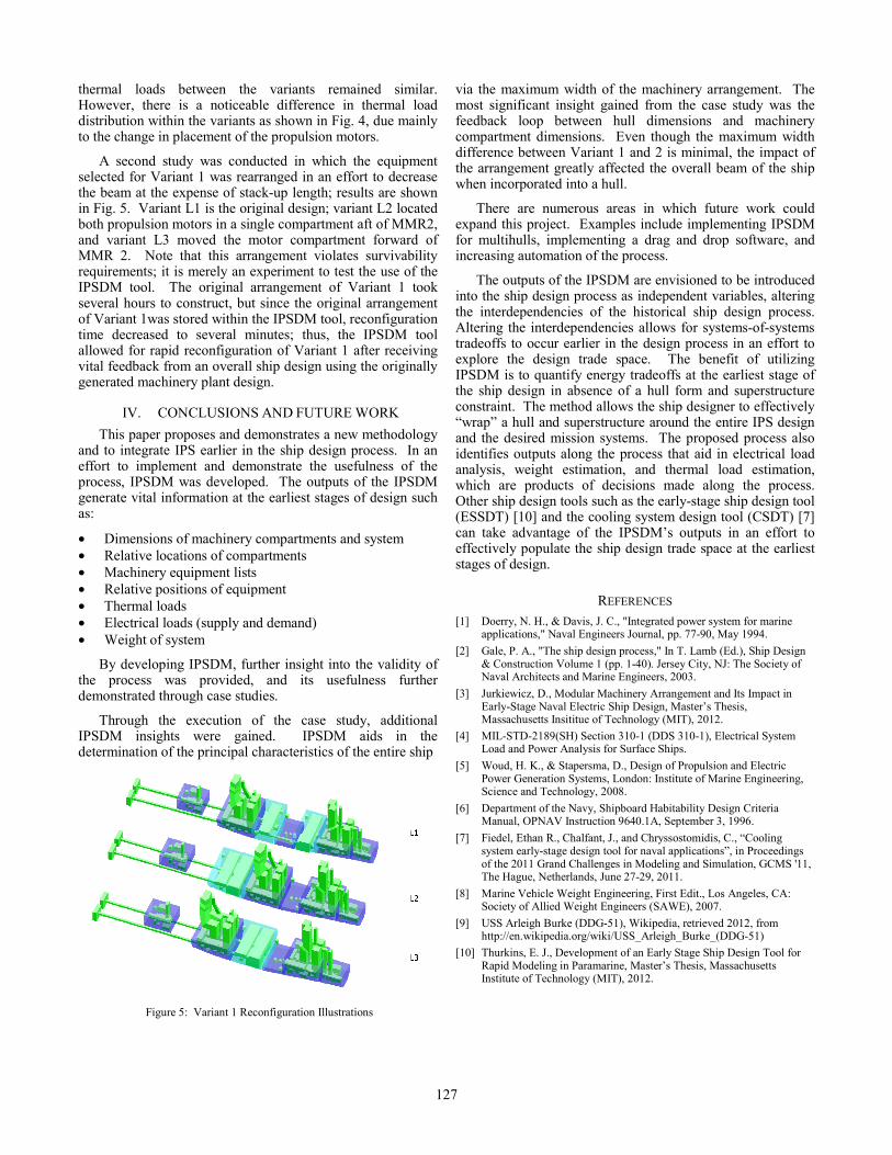
A second study was conducted in which the equipment selected for Variant 1 was rearranged in an effort to decrease the beam at the expense of stack-up length; results are shown in Fig. 5. Variant L1 is the original design; variant L2 located both propulsion motors in a single compartment aft of MMR2, and variant L3 moved the motor compartment forward of MMR 2. Note that this arrangement violates survivability requirements; it is merely an experiment to test the use of the IPSDM tool. The original arrangement of Variant 1 took several hours to construct, but since the original arrangement of Variant 1was stored within the IPSDM tool, reconfiguration time decreased to several minutes; thus, the IPSDM tool allowed for rapid reconfiguration of Variant 1 after receiving vital feedback from an overall ship design using the originally generated machinery plant design.
IV. CONCLUSIONS AND FUTURE WORK This paper proposes and demonstrates a new methodology
and to integrate IPS earlier in the ship design process. In an effort to implement and demonstrate the usefulness of the process, IPSDM was developed. The outputs of the IPSDM generate vital information at the earliest stages of design such as:
• Dimensions of machinery compartments and system • Relative locations of compartments • Machinery equipment lists • Relative positions of equipment • Thermal loads • Electrical loads (supply and demand) • Weight of system
By developing IPSDM, further insight into the validity of the process was provided, and its usefulness further demonstrated through case studies.
Through the execution of the case study, additional IPSDM insights were gained. IPSDM aids in the determination of the principal characteristics of the entire ship
via the maximum width of the machinery arrangement. The most significant insight gained from the case study was the feedback loop between hull dimensions and machinery compartment dimensions. Even though the maximum width difference between Variant 1 and 2 is minimal, the impact of the arrangement greatly affected the overall beam of the ship when incorporated into a hull.
There are numerous areas in which future work could expand this project. Examples include implementing IPSDM for multihulls, implementing a drag and drop software, and increasing automation of the process.
The outputs of the IPSDM are envisioned to be introduced into the ship design process as independent variables, altering the interdependencies of the historical ship design process. Altering the interdependencies allows for systems-of-systems tradeoffs to occur earlier in the design process in an effort to explore the design trade space. The benefit of utilizing IPSDM is to quantify energy tradeoffs at the earliest stage of the ship design in absence of a hull form and superstructure constraint. The method allows the ship designer to effectively “wrap” a hull and superstructure around the entire IPS design and the desired mission systems. The proposed process also identifies outputs along the process that aid in electrical load analysis, weight estimation, and thermal load estimation, which are products of decisions made along the process. Other ship design tools such as the early-stage ship design tool (ESSDT) [10] and the cooling system design tool (CSDT) [7] can take advantage of the IPSDM’s outputs in an effort to effectively populate the ship design trade space at the earliest stages of design.
REFERENCES [1] Doerry, N. H., & Davis, J. C., "Integrated power system for marine
applications," Naval Engineers Journal, pp. 77-90, May 1994. [2] Gale, P. A., "The ship design process," In T. Lamb (Ed.), Ship Design
& Construction Volume 1 (pp. 1-40). Jersey City, NJ: The Society of Naval Architects and Marine Engineers, 2003.
[3] Jurkiewicz, D., Modular Machinery Arrangement and Its Impact in Early-Stage Naval Electric Ship Design, Master’s Thesis, Massachusetts Insititue of Technology (MIT), 2012.
[4] MIL-STD-2189(SH) Section 310-1 (DDS 310-1), Electrical System Load and Power Analysis for Surface Ships.
[5] Woud, H. K., & Stapersma, D., Design of Propulsion and Electric Power Generation Systems, London: Institute of Marine Engineering, Science and Technology, 2008.
[6] Department of the Navy, Shipboard Habitability Design Criteria Manual, OPNAV Instruction 9640.1A, September 3, 1996.
[7] Fiedel, Ethan R., Chalfant, J., and Chryssostomidis, C., “Cooling system early-stage design tool for naval applications”, in Proceedings of the 2011 Grand Challenges in Modeling and Simulation, GCMS '11, The Hague, Netherlands, June 27-29, 2011.
[8] Marine Vehicle Weight Engineering, First Edit., Los Angeles, CA: Society of Allied Weight Engineers (SAWE), 2007.
[9] USS Arleigh Burke (DDG-51), Wikipedia, retrieved 2012, from http://en.wikipedia.org/wiki/USS_Arleigh_Burke_(DDG-51)
[10] Thurkins, E. J., Development of an Early Stage Ship Design Tool for Rapid Modeling in Paramarine, Master’s Thesis, Massachusetts Institute of Technology (MIT), 2012.
Figure 5: Variant 1 Reconfiguration Illustrations
127