Embed Size (px)
Citation preview

90 MCB
Technical Information Version 2.11
MODULAR CIRCUIT BREAKERS FOR CIRCUIT PROTECTION
For technical information contact the Technical Assistance Service or visit gewiss.com
TYPE MTC MTMTC45 MTC60 MTC100 MT 45 MT 60
Rated current (In) (A) 2-32 6-32 6-32 6-40 1-63Utilization category A A A A ARated operational voltage (Ue) (V) 230/400 - 240/415 230/400 - 240/415 230 - 240 230/400 - 240/415 230/400 - 240/415Minimum operating voltage (Ue min) (V) 12 AC/DC 12 AC/DC 12 AC/DC 12 AC/DC 12 AC/DCMaximum operating voltage (Ue max) (V) 440 AC/ 220 DC 440 AC/ 220 DC 253 AC/ 110 DC 440 AC/ 220 DC 440 AC/ 220 DCInsulation voltage (Ui) (V) 500 500 500 500 500Rated frequency (Hz) 50 / 60 50 / 60 50 / 60 50 / 60 50 / 60Rated impulse withstand voltage (Uimp) (kV) 4 4 4 4 4Overvoltage category: III III III III IIINumber of poles 1 1+N,2 3,4 1+N,2 3,4 1+N,2 1,1+N 2,3,4 1, 1+N 2,3,4
Energy limiting class (B and C curve): 3 3 3 33 (≤16A)1 (>16A)
3 3 3 3 3
Breaking capacity
Alternating current
IEC/EN 60898-1Icn (A) 4500 6000 (1) 6000 10000(1) 4500 6000Ics (A) 1 Icn 1 Icn 0.75 Icn 1 Icn 1 Icn
IEC/EN 60947-2Icu 230/240 V (kA) 4.5 6 6 7.5 7.5 10 4.5 6 10 20
400/415 V (kA) - - 4.5 - 6 - - 6 - 10Ics (kA) 100% Icu 100% Icu 75% Icu 100% Icu 75% Icu
Direct current IEC/EN 60947-2
Icu (1 pole)50 V (kA)
6 10 - 6 10Ics 6 10 - 6 10Icu (2 poles in series)
110 V (kA)6 10 10 (15 at 50V) 6 10
Ics 6 10 10 (15 at 50V) 6 6Icu (4 poles in series)
220 V (kA)4.5 6 - 4.5 10
Ics 4.5 6 - 4.5 10
Wiring cable section (mm2)rigid ≤ 1x16 - ≤ 1x10+ 1x6 ≤ 1x16 - ≤1x10+ 1x6 ≤1x16 - ≤1x10+1x6 ≤ 1x35 - ≤ 2x16 - ≤ 1x16+2x10 ≤ 1x35 - ≤ 2x16 - ≤ 1x16+2x10flexible ≤ 1x10- ≤ 2x6 ≤1x10 - ≤ 2x6 ≤1x10 - ≤ 2x6 ≤ 1x35 - ≤ 2x16 - ≤ 1x16+2x10 ≤ 1x35 - ≤ 2x16 - ≤ 1x16+2x10
Screwdriver suggested: PZ2 PZ2 PZ2 PZ2 PZ2Electrical endurance: 10000 10000 10000 10000 10000Mechanical endurance: 20000 20000 20000 20000 20000Max. no. of usable modular accessories: 2 2 2 2 2Upline/downline power supply: yes yes yes yes yesON/OFF status displayed: yes yes yes yes yesMounting position: any any any any anyType of residual current device: - - - Add-on RCD BD Add-on RCD BDRated tightening torque: (Nm) 1.2 1.2 1.2 2 2
Degree of protection:terminals IP20 IP20 IP20 IP20 IP20front IP40 IP40 IP40 IP40 IP40
Pollution degree: 2 2 2 2 2Tropicalization: 55°C - RH 95% 55°C - RH 95% 55°C - RH 95% 55°C - RH 95% 55°C - RH 95%Reference temperature: (°C) 30 30 30 30 30Operating temperature: (°C) -25 +60 -25 +60 -25 +60 -25 +60 -25 +60Stocking temperature: (°C) -40 +70 -40 +70 -40 +70 -40 +70 -40 +70Double connection (cable+fork busbar) no no no yes (only downstream) yes (only downstream)Weight: (g) 135 (per module) 135 (per module) 135 (per module) 145 (per pole) 145 (per pole)
Tripping characteristic C C B C C B C B DRated currents available In: (A) - - - - 1 - -
2 - - - 2 - -- - - - 3 - -- - - - 4 - -6 6 6 6 6 6 6 6 610 10 10 10 10 10 10 10 1013 13 13 13 13 13 13 13 1316 16 16 16 16 16 16 16 1620 20 20 20 20 20 20 20 2025 25 25 25 25 25 25 25 2532 32 32 32 32 32 32 32 32- - - 40 40 40 40 40- - - - 50 50 -- - - - 63 63 -- - - - -- - - - -- - - - -
(1) Breaking capacity of the single pole Icn1=4500A (2) ≤95mm2 with reduced connection terminal (width connection < 17mm)
MCB - MTC - MT - MTHP
Technical data
90 MCB
2Technical Information Version 2.1
MODULAR CIRCUIT BREAKERS FOR CIRCUIT PROTECTION
For technical information contact the Technical Assistance Service or visit gewiss.com
MT MTHPMT 100 MT 250 MTHP 160 MTHP 250
1-25 32-63 6-20 25 32-40 50-63 63-125 20-63A A A A A A A A
230/400 - 240/415 230/400 - 240/415 230/400 - 240/415 230/400 - 240/415 230/400 - 240/415 230/400 - 240/415 230/400 230/40012 AC/DC 12 AC/DC 12 AC/DC 12 AC/DC 12 AC/DC 12 AC/DC 12 AC/DC 12 AC/DC
440 AC/220 DC 440 AC/220 DC 440 AC/220 DC 440 AC/220 DC 440 AC/220 DC 440 AC/220 DC 440 AC/220 DC 440 AC/220 DC500 500 500 500 500 500 500 500
50/60 50/60 50/60 50/60 50/60 50/60 50/60 50/604 4 4 4 4 4 6 6III III III III III III IV IV
1 2 3,4 1 2 3,4 1 2 3,4 1 2 3,4 1 2 3,4 1 2 3,4 1 2,3,4 1 2 3,4
3 3 3 3 3 3 - - - - - - - - - - - - - - - - -
10000 10000 25000 20000 15000 12500 10000 250000.75 Icn 0.75 Icn 0.75 Icn 0.75 Icn 0.75 Icn 0.75 Icn 0.75 Icn 0.75 Icn
15 30 25 12.5 25 20 25 50 40 20 40 30 15 30 25 15 25 20 16 20 25 50 30- 20 15 - 15 12.5 - 30 25 - 25 20 - 20 15 - 15 15 4.5 16 6 25 25
50% Icu 50% Icu 50% Icu 50% Icu 50% Icu 50% Icu 50% Icu 75% Icu10 10 20 20 20 20 10 2510 10 15 15 15 15 10 2015 15 25 25 25 25 15 3015 15 20 20 20 20 12 2515 15 25 25 25 25 15 2512 12 20 20 20 20 12 20
1x35 - . 2x16 - . 1x16+2x10 ≤ 1x35 - ≤ 2x16 - ≤ 1x16+2x10 ≤ 1x35 - ≤ 2x16 - ≤ 1x16+2x10 ≤ 1x35 - ≤ 2x16 - ≤ 1x16+2x10 ≤ 1x35 - ≤ 2x16 - ≤ 1x16+2x10 ≤ 1x35 - ≤ 2x16 - ≤ 1x16+2x10 ≤ 1x70 - ≤ 2x25 - ≤ 2x25+1x10 ≤ 1x70 - ≤ 2x25 - ≤ 2x25+1x101x35 - . 2x16 - . 1x16+2x10 ≤ 1x35 - ≤ 2x16 - ≤ 1x16+2x10 ≤ 1x35 - ≤ 2x16 - ≤ 1x16+2x10 ≤ 1x35 - ≤ 2x16 - ≤ 1x16+2x10 ≤ 1x35 - ≤ 2x16 - ≤ 1x16+2x10 ≤ 1x35 - ≤ 2x16 - ≤ 1x16+2x10 ≤ 1x50(2) - ≤ 2x25 - ≤ 3x16 ≤ 1x50(2) - ≤ 2x25 - ≤ 3x16
PZ2 PZ2 PZ2 PZ2 PZ2 PZ2 PZ2 PZ210000 10000 10000 10000 10000 10000 10000 1000020000 20000 20000 20000 20000 20000 20000 20000
2 2 2 2 2 2 2 2yes yes yes yes yes yes yes yesyes yes yes yes yes yes yes yesany any any any any any any any
Add-on RCD BD Add-on RCD BD Add-on RCD BD Add-on RCD BD Add-on RCD BD Add-on RCD BD Add-on RCD BDHP Add-on RCD BDHP2 2 2 2 2 2 3.5 / 3 (terminal) 3.5 / 3 (terminal)
IP20 IP20 IP20 IP20 IP20 IP20 IP20 IP20IP40 IP40 IP40 IP40 IP40 IP40 IP40 IP40
2 2 2 2 2 2 2 255°C - RH 95% 55°C - RH 95% 55°C - RH 95% 55°C - RH 95% 55°C - RH 95% 55°C - RH 95% 55°C - RH 95% 55°C - RH 95%
30 30 30 30 30 30 30 30-25 +60 -25 +60 -25 +60 -25 +60 -25 +60 -25 +60 -25 +60 -25 +60-40 +70 -40 +70 -40 +70 -40 +70 -40 +70 -40 +70 -40 +70 -40 +70
yes (only downstream) yes (only downstream) yes (only downstream) yes (only downstream) yes (only downstream) yes (only downstream) no no145 (per pole) 145 (per pole) 145 (per pole) 145 (per pole) 145 (per pole) 145 (per pole) 250 (per pole) 250 (per pole)
C B D C C D C- - 1 - - - -- - 2 - - - -- - 3 - - - -- - 4 - - - -6 6 6 6 - - -10 10 10 10 - - -13 13 13 - - - -16 16 16 16 - - -20 20 20 20 - - 2025 25 25 25 - - 2532 32 32 32 - - 3240 40 40 40 - - 4050 50 - 50 - - 5063 63 - 63 - 63 63- - - - 80 80 -- - - - 100 100 -- - - - 125 - -

90 MCB
Technical Information Version 2.13
MODULAR CIRCUIT BREAKERS FOR CIRCUIT PROTECTION
For technical information contact the Technical Assistance Service or visit gewiss.com
The position of the releases on the front, with magnetic turns and opposing arc chute chambers, allows a notable reduction in arc time and short-circuit strain on the mechanism. It has therefore been possible to halve the system and lighten the mechanism, which has short pre-arc times thanks to the reduced energy. The new mechanism has been sized and optimised by means of a sophisticated planning, engineering and testing programme.
Manual control lever with a position coherent with the contacts, allowing the circuit breaker to be used as a switch disconnector (in compliance with Standard CEI 64-8)
Toggle joint tripping mechanism with tripping accelerator for short-circuit condition
Electromagnets for instantaneous short-circuit tripping
Silver-graphite contacts to maintain electrical characteristics over time
Magnetic turns in the arc chute chambers
Arc chute chambers with 12 reeds in a ferromagnetic material
Shell-type terminals with anti-loosening tightening system
CHARACTERISTICS OF THE NEW KINEMATIC MECHANISM OF THE MTC COMPACT CIRCUIT BREAKERS

90 MCB
4Technical Information Version 2.1
MODULAR CIRCUIT BREAKERS FOR CIRCUIT PROTECTION
For technical information contact the Technical Assistance Service or visit gewiss.com
MTC 45 - 60 - 100 Compact miniature circuit breakers
General characteristicsThe MTC compact miniature circuit breakers are characterised by the reduced overall dimensions they occupy in the board, and their full modularity with electrical auxiliaries and modular accessories. It is therefore possible to position all the equipment necessary to protect and control the service electrical system centrally, in small spaces. The innovations are based on a new kinematic mechanism for activating the circuit breaker (with a world-wide Gewiss patent) which helps to increase normal performance while reducing the occupied overall dimensions by 50%. This new device makes it possible to include a bipolar circuit breaker in a single 18mm module, with both poles protected by both magnetic and thermal release.
Temperature performanceIn plant engineering situations where the ambient temperature is higher than the standard 30°C reference temperature, the circuit breakers may be subject to untimely tripping, i.e. inappropriate switch-off, because the rise in temperature is interpreted as overcurrent. In fact ambient temperature affects the initial deformation of the bimetal; at a temperature above 30°, the thermal release intervenes more quickly, acting like a relay with a lower rated current.It is therefore imperative to take into consideration the temperature performance of the rated current if the circuit breaker is installed in a place with a temperature above 30°. The following tables show the max. operating currents corresponding to the different temperatures.
MTC 45 - 60 - 100 COMPACT MINIATURE CIRCUIT BREAKERS
In (A)Temperature
10°C 20°C 30°C 40°C 50°C 60°C
2 2.1 2.05 2 1.9 1.8 1.55
6 7.2 6.6 6 5.7 5.3 5
10 11.8 10.8 10 9.6 9.1 8.6
13 15 14 13 12.4 11.7 11
16 18.2 17.2 16 15.2 14.3 13.4
20 22.8 21.4 20 19.5 18.9 18.4
25 28.5 26.8 25 24 23 22
32 36.5 34.2 32 30.8 29.5 28
Power loss per poleThe following table shows the power loss values for the MTC miniature circuit breakers, so you can check the overtemperature values in the board in relation to Standards EN 60439 and CEI 17 - 43. You can also check whether the power loss of the devices is lower than - or equal to - the level that the enclosure is able to disperse, in accordance with Standards CEI 23 - 49 and CEI 23 - 51.
MTC 45 - 60 - 100 COMPACT MINIATURE CIRCUIT BREAKERS
In (A)2 6 10 13 16 20 25 32
Pole N Pole N Pole N Pole N Pole N Pole N Pole N Pole N
R (mΩ) 450 1.07 29.4 2.6 20.3 2.6 14.2 2.6 8.7 2.6 5.7 2.6 5.3 2.6 3.4 2.6
P (W) 1.8 0.04 1.06 0.09 2.03 0.26 2.4 0.44 2.22 0.67 2.27 1.04 3.34 2 3.45 2.66
POWER LOSS VALUES AND TEMPERATURE PERFORMANCE

90 MCB
Technical Information Version 2.15
MODULAR CIRCUIT BREAKERS FOR CIRCUIT PROTECTION
For technical information contact the Technical Assistance Service or visit gewiss.com
MT 45 - MT 60 - MT 100 - MT 250 Miniature circuit breakers
General characteristicsThanks to a wide range and excellent performance, the MT miniature circuit breakers allow the creation of electrical systems in which the use of MTCs alone would be insufficient.The MT range, with rated current from 1 to 63A, characteristics B, C and D, and a breaking capacity of 6, 10 and 25 kA, satisfies all installation needs in the commercial, advanced commercial and industrial sectors. Thanks to the full modularity with the residual current devices, electrical auxiliaries and modular accessories, the MT range guarantees the optimum solution for every plant engineering context.
MT 45 - MT 60 - 100 - 250 TEMPERATURE PERFORMANCE
In (A)Temperature (°C)
15 20 30 40 50 60
1 1.07 1.04 1.00 0.97 0.93 0.90
2 2.14 2.07 2.00 1.93 1.86 1.79
3 3.21 3.11 3.00 2.90 2.79 2.69
4 4.28 4.14 4.00 3.86 3.72 3.58
6 7 6.67 6.00 5.52 4.84 3.96
10 11.2 10.8 10.0 8.9 7.95 7.16
13 14.4 13.9 13.0 11.9 10.9 10
16 17.6 17.1 16.0 14.9 13.9 12.8
20 22 21.3 20.0 17.8 16.1 15.1
25 28.2 27.1 25.0 23.4 21.3 18.8
32 37 35.3 32.0 30.8 27.8 23.1
40 45 43.3 40.0 34.8 30 28
50 57.5 55 50.0 46.7 42.1 36.3
63 70 67.7 63.0 59.9 52.7 41.25
MT 45 - MT 60 - 100 - 250 POWER LOSS PER POLE
In (A)
Tripping characteristic
B C D
P (W) R (mΩ) P (W) R (mΩ) P (W) R (mΩ)
1 - - 2.20 2200 - -
2 - - 2.70 675 - -
3 - - 2.30 256 - -
4 - - 2.20 138 - -
6 1.42 39 1.42 39 0.80 22
10 2.13 21 2.13 21 1.20 12
13 2.1 12.4 2.1 12.4 1.3 7.7
16 2.80 11 2.80 11 1.60 6.3
20 2.56 6.4 2.56 6.4 2.10 5.3
25 3.10 5 3.10 5 2.00 3.2
32 3.00 2.9 3.00 2.9 2.40 2.4
40 3.10 1.9 3.10 1.9 2.70 1.7
50 3.87 1.5 3.87 1.5 - -
63 4.51 1.2 4.51 1.2 - -
MTHP 160 - MTHP 250 High performance miniature circuit breakers
General characteristicsThanks to a wide range and excellent performance, the MTHP miniature circuit breakers allow the creation of electrical systems in which the use of MTCs and MTs alone would be insufficient. The MTHP range, with rated current from 20 to 125A, characteristics C and D, and a breaking capacity of 10 and 25 kA, satisfies all installation needs in the commercial, advanced commercial and industrial sectors. Thanks to the full modularity with the residual current devices, electrical auxiliaries and modular accessories, the MTHP range guarantees the optimum solution for every plant engineering context.
Note: power loss values are suitable also for neutral of 1P+N versions.
MTHP 160 - 250 TEMPERATURE PERFORMANCE
In (A)Temperature
20°C 30°C 40°C 50°C 60°C
20 21 20 17.5 16 15
25 26 25 24 22 19
32 35 32 30 28 23
40 42 40 35 33 28
50 55 50 47 42 36
63 66 63 59 53 48
80 85 80 75 70 63
100 107 100 93 87 78
125 135 125 115 107 97
MTHP 160 - 250 POWER LOSS PER POLE
In (A)20 25 32 40 50 63 80 100 125
Power loss (W)
MTHP 250 2.8 2.7 3.1 3.5 4.2 5.6 - - -
MTHP 160 - - - - - 5.6 5.6 7.4 11
POWER LOSS VALUES AND TEMPERATURE PERFORMANCE

90 MCB
6Technical Information Version 2.1
MODULAR CIRCUIT BREAKERS FOR CIRCUIT PROTECTION
For technical information contact the Technical Assistance Service or visit gewiss.com
MTC 45 - 60 - 100 Characteristic CMT 45 - MT 60 - 100 - 250 Characteristic CMTHP 160 - 250 Characteristic C
3
MT 45 - MT 60 - 100 Characteristic BMTC 60 Characteristic B
20
MT 60 - 100 Characteristic DMTHP 160 Characteristic D
Trippingcharacteristic
B C D
In from 6 to 63 A from 1 to 125 A from 6 to 100 A
Thermal release
Inf 1,13 In 1,13 In 1,13 In
If 1,45 In 1,45 In 1,45 In
t < 1 h < 1 h < 1 h
Magnetic release
Inf 3 In 5 In 10 In
If 5 In 10 In 20 In
t istantaneous istantaneous istantaneous
In =rated currentInf = conventional non-trpping currentIf = conventional tripping currentt = tripping time
B tripping curve: tripping characteristic for the protection of electrical resistive loads (for example: heating) and very long electrical ditribution lines.
C tripping curve: tripping characteristic for the protection of general electrical resistive or slight inductive loads (for example: fluorescent lamps).
D tripping curve: tripping characteristic for the protection of electrical heavy inductive loads or high starting curents (for example: electrical engines).
TRIPPING CHARACTERISTICS IN ALTERNATING CURRENT (EN 60898)

90 MCB
Technical Information Version 2.17
MODULAR CIRCUIT BREAKERS FOR CIRCUIT PROTECTION
For technical information contact the Technical Assistance Service or visit gewiss.com
MTC 45 - 1P+N, 2P - 230V versions MTC 45 - 1P - 230V and 3P,4P - 230/400V versions
MTC 60 - 3P,4P - 230/400V versionsMTC 60 - 1P+N, 2P - 230V versions
MTC 100 - 1P+N, 2P - 230V versions
IRMS (A)
IRMS (A)IRMS (A)
IRMS (A)
IRMS (A)
IRMS
IRMS estimated peak
IRMS estimated
IRMSlimited peak
IRMSlimited
ti t
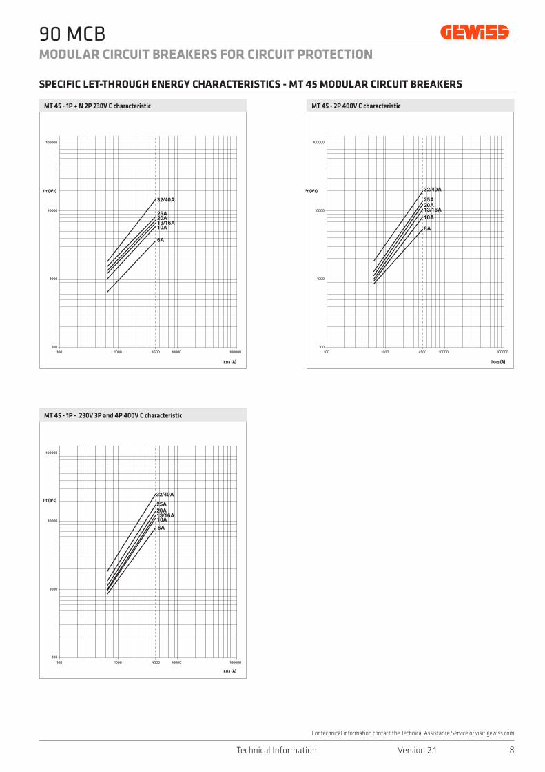
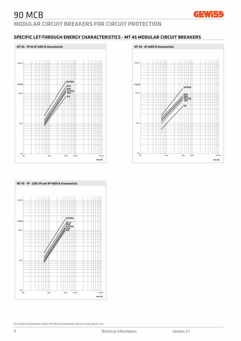
The curves above give the values of the specific let-through energy in relation to the short-circuit current expressed in A. Every curve refers to each rated current value of circuit breaker.
SPECIFIC LET-THROUGH ENERGY CHARACTERISTICS - MTC MODULAR COMPACT CIRCUIT BREAKERS
90 MCB
8Technical Information Version 2.1
MODULAR CIRCUIT BREAKERS FOR CIRCUIT PROTECTION
For technical information contact the Technical Assistance Service or visit gewiss.com
MT 45 - 1P - 230V 3P and 4P 400V C characteristic
MT 45 - 1P + N 2P 230V C characteristic MT 45 - 2P 400V C characteristic
I2t (A2s)
I2t (A2s)
I2t (A2s)
IRMS (A)
IRMS (A)
IRMS (A)
SPECIFIC LET-THROUGH ENERGY CHARACTERISTICS - MT 45 MODULAR CIRCUIT BREAKERS
90 MCB
Technical Information Version 2.19
MODULAR CIRCUIT BREAKERS FOR CIRCUIT PROTECTION
For technical information contact the Technical Assistance Service or visit gewiss.com
MT 45 - 2P 400V B characteristic
MT 45 - 1P - 230V 3P and 4P 400V B characteristic
I2t (A2s)
I2t (A2s)
IRMS (A)
IRMS (A)
MT 45 - 1P+N 2P 230V B characteristic
I2t (A2s)
IRMS (A)
SPECIFIC LET-THROUGH ENERGY CHARACTERISTICS - MT 45 MODULAR CIRCUIT BREAKERS
90 MCB
10Technical Information Version 2.1
MODULAR CIRCUIT BREAKERS FOR CIRCUIT PROTECTION
For technical information contact the Technical Assistance Service or visit gewiss.com
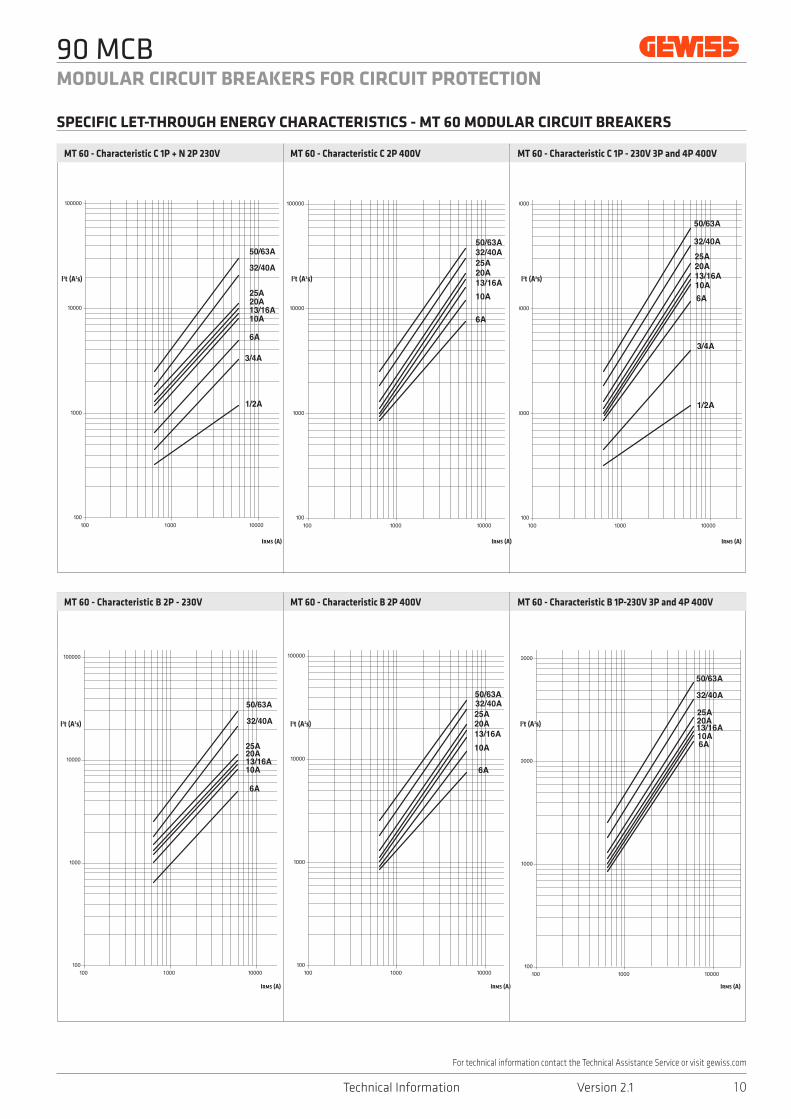
MT 60 - Characteristic C 1P + N 2P 230V
MT 60 - Characteristic B 2P - 230V
MT 60 - Characteristic C 2P 400V
MT 60 - Characteristic B 2P 400V
MT 60 - Characteristic C 1P - 230V 3P and 4P 400V
MT 60 - Characteristic B 1P-230V 3P and 4P 400V
I2t (A2s) I2t (A2s)
IRMS (A)IRMS (A)IRMS (A)
I2t (A2s)
I2t (A2s) I2t (A2s)
IRMS (A)IRMS (A)IRMS (A)
I2t (A2s)
SPECIFIC LET-THROUGH ENERGY CHARACTERISTICS - MT 60 MODULAR CIRCUIT BREAKERS
90 MCB
Technical Information Version 2.111
MODULAR CIRCUIT BREAKERS FOR CIRCUIT PROTECTION
For technical information contact the Technical Assistance Service or visit gewiss.com
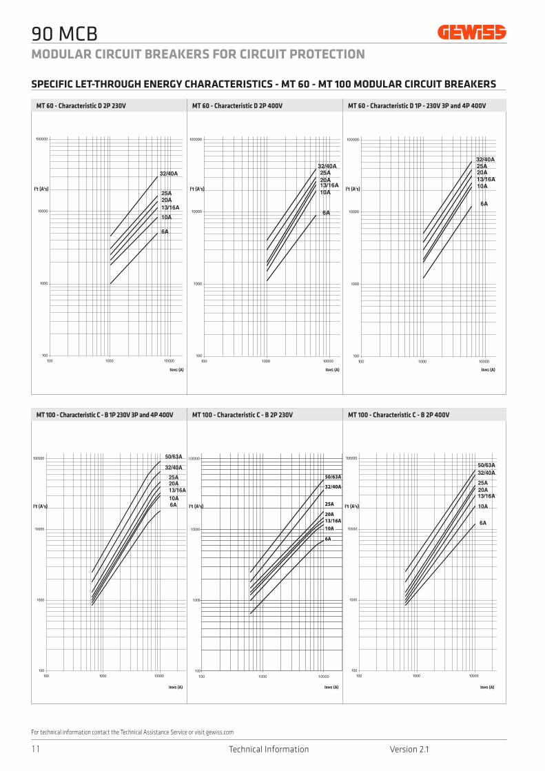
MT 60 - Characteristic D 2P 230V
MT 100 - Characteristic C - B 1P 230V 3P and 4P 400V
MT 60 - Characteristic D 2P 400V
MT 100 - Characteristic C - B 2P 230V
MT 60 - Characteristic D 1P - 230V 3P and 4P 400V
MT 100 - Characteristic C - B 2P 400V
MT100 CURVA C - B 2P 230V
100
1000
10000
100000
1000000
Icc (A)
I²t (A
²s) 13/16A
20A
25A
50/63A
32/40A
6A
10A
I2t (A2s) I2t (A2s)
IRMS (A)IRMS (A)IRMS (A)
I2t (A2s)
I2t (A2s) I2t (A2s)
IRMS (A)IRMS (A)IRMS (A)
I2t (A2s)
SPECIFIC LET-THROUGH ENERGY CHARACTERISTICS - MT 60 - MT 100 MODULAR CIRCUIT BREAKERS

90 MCB
12Technical Information Version 2.1
MODULAR CIRCUIT BREAKERS FOR CIRCUIT PROTECTION
For technical information contact the Technical Assistance Service or visit gewiss.com
MT 100 - Characteristic D 1P-230V 3P and 4P 400V
MT 250 - Characteristic C 1P-230V 3P and 4P 400V
MT 100 - Characteristic D 2P 230V
MT 250 - Characteristic C 2P 230V
MT 100 - Characteristic D 2P 400V
MT 250 - Characteristic C 2P 400V
I2t (A2s) I2t (A2s)I2t (A2s)
I2t (A2s) I2t (A2s)I2t (A2s)
IRMS (A) IRMS (A) IRMS (A)
IRMS (A) IRMS (A) IRMS (A)
SPECIFIC LET-THROUGH ENERGY CHARACTERISTICS - MT 100 - MT 250 MODULAR CIRCUIT BREAKERS

90 MCB
Technical Information Version 2.113
MODULAR CIRCUIT BREAKERS FOR CIRCUIT PROTECTION
For technical information contact the Technical Assistance Service or visit gewiss.com
MTHP250 - Characteristic C 2P 230V
MTHP160 - Characteristic C-D 2P 230V
MTHP250 - Characteristic C 2P 400V
MTHP160 - Characteristic C-D 2P 400V
MTHP250 - Characteristic C 1P 230V 3P 4P 400V
MTHP160 - Characteristic C-D 1P 230V 3P 4P 400V
I2t (A2s) I2t (A2s)I2t (A2s)
IRMS (A) IRMS (A) IRMS (A)
I2t (A2s) I2t (A2s) I2t (A2s)
IRMS (A) IRMS (A) IRMS (A)
SPECIFIC LET-THROUGH ENERGY CHARACTERISTICS - MTHP 250 MODULAR CIRCUIT BREAKERS
SPECIFIC LET-THROUGH ENERGY CHARACTERISTICS - MTHP 160 MODULAR CIRCUIT BREAKERS

90 MCB
14Technical Information Version 2.1
MODULAR CIRCUIT BREAKERS FOR CIRCUIT PROTECTION
For technical information contact the Technical Assistance Service or visit gewiss.com
MTC - 1P + N 2P 230V version
MT - 1P + N 2P 230V version
MTC - 1P 230V - 3P 4P 400V version
MT - 1P 230V - 2P 3P 4P 400V version MTHP - 1P 230V - 2P 3P 4P 400V version
1011
10
1011
10
Peak current (kA)
Unlimited peak current Unlimited peak current
Peak current (kA)
Estimated short-circuit current (kA)
10 3011
10
10 3011
10
1011
10
Estimated short-circuit current (kA) Estimated short-circuit current (kA) Estimated short-circuit current (kA)
Peak current (kA)
Unlimited peak current
Peak current (kA)
Unlimited peak current
Peak current (kA)
Unlimited peak current
Estimated short-circuit current (kA)
IRMS
IRMS estimated peak
IRMS estimated
IRMSlimited peak
IRMSlimited
ti t
The following curves give the values of the peak current in relation to the estimated short-circuit current expressed in kA. Every curve refers to each rated current value of circuit breaker.
PEAK CURRENT LIMITATION CHARACTERISTICS

90 MCB
Technical Information Version 2.115
MODULAR CIRCUIT BREAKERS FOR CIRCUIT PROTECTION
For technical information contact the Technical Assistance Service or visit gewiss.com
The interruption of direct current is more difficult to achieve than the alternating current because the direct current doesn’t go through zero at each half cycle. Therefore, it is necessary to connect in series the poles of the same circuit breaker so that the increase of the resistance, thus created, causes the decrease of the current until its cancellation.Moreover, if the operating voltage of the system increases, also the number of poles connected in series must increase.
For a correct choice of a circuit breaker to protect DC electrical loads, it’s suggested to keep in mind these following 3 factors:
1. Operating voltage, which effects the number of poles to be connected in series. The maximum operating voltage in direct current for Gewiss circuit breaker is equal to 220V by connecting 4 poles in series (max 50V per pole).
2. Short-circuit current, alleged in the installation point that effects the choice of circuit breaker type.
3. Operating current and the type of electrical load, which effect the rated current of the circuit breaker and its tripping characteristic. The rated current of the circuit breaker for DC application must be higher than the operating current of electrical load and must be lower or equal to the
capacity of the cable, as well as alternating current situation. In addition to inrush current, the choice of tripping characteristics must consider that the DC magnetic trip threshold is greater than alternating current.
Hereafter the tripping characteristics according to EN 60898 of circuit breakers used in direct current.
BREAKING CAPACITY Icu (kA)
Circuit breaker typeOperating voltage (V)
50 110 220
MTC 45 6 6 4.5
MTC 60 10 10 6
MTC 100 - 10 (*) -
MT 45 6 6 4.5
MT 60 10 10 10
MT 100 10 15 15
MT 250 20 25 25
MTHP 160 10 15 15
MTHP 250 25 30 25
(*) 15 kA at 50V
1 pole 50V DC 2 pole in series 110V DC4 pole in series 220V DC
One pole is earthed Middle point is earthed
HOW TO CHOOSE CIRCUIT BREAKERS FOR DIRECT CURRENT APPLICATIONS
90 MCB
16Technical Information Version 2.1
MODULAR CIRCUIT BREAKERS FOR CIRCUIT PROTECTION
For technical information contact the Technical Assistance Service or visit gewiss.com
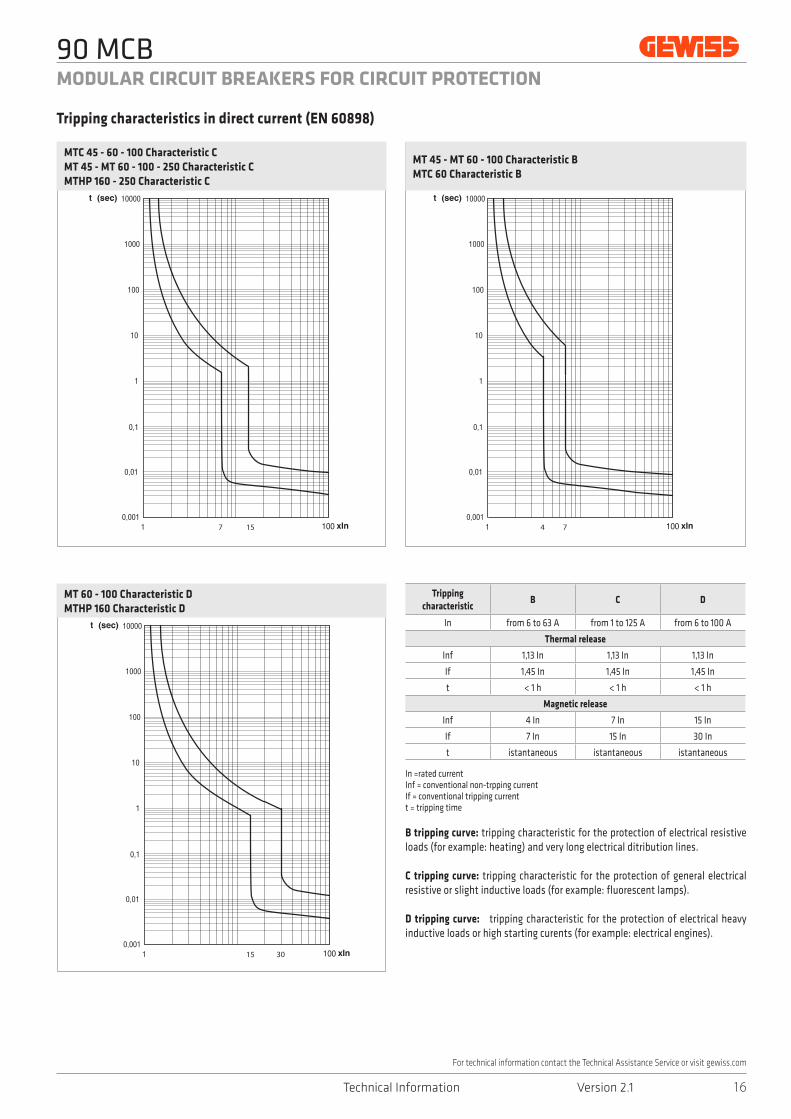
Tripping characteristic
B C D
In from 6 to 63 A from 1 to 125 A from 6 to 100 A
Thermal release
Inf 1,13 In 1,13 In 1,13 In
If 1,45 In 1,45 In 1,45 In
t < 1 h < 1 h < 1 h
Magnetic release
Inf 4 In 7 In 15 In
If 7 In 15 In 30 In
t istantaneous istantaneous istantaneous
Tripping characteristics in direct current (EN 60898)
MTC 45 - 60 - 100 Characteristic CMT 45 - MT 60 - 100 - 250 Characteristic CMTHP 160 - 250 Characteristic C
MT 45 - MT 60 - 100 Characteristic BMTC 60 Characteristic B
MT 60 - 100 Characteristic DMTHP 160 Characteristic D
In =rated currentInf = conventional non-trpping currentIf = conventional tripping currentt = tripping time
B tripping curve: tripping characteristic for the protection of electrical resistive loads (for example: heating) and very long electrical ditribution lines.
C tripping curve: tripping characteristic for the protection of general electrical resistive or slight inductive loads (for example: fluorescent lamps).
D tripping curve: tripping characteristic for the protection of electrical heavy inductive loads or high starting curents (for example: electrical engines).
Curva B C DIn da 6 a 63 A da 1 a 125 A da 6 a 100 A
Intervento termicoInf 1,13 In 1,13 In 1,13 In
If 1,45 In 1,45 In 1,45 In
t < 1 h < 1 h < 1 h
Intervento magneticoInf 4 In 7 In 15 In
If 7 In 15 In 30 In
t istantaneo istantaneo istantaneo
CURVE CARATT ER ISTICH E
CURVE DI INTERVEN TO (EN 60898)
15
MT 60 - 100 Curva DMTHP 160 Curva D
In = corrente nominale Inf = corrente convenzionale di non intervento If = corrente convenzionale di intervento t = tempo di intervento
Curva B: caratteristica di intervento indicata per la protezione di carichi resistivi (es. apparecchi di riscaldamento elettrico) e linee elettriche di notevole lunghezza.
Curva C: caratteristica di intervento adatta per la protezione in generale di carichi resistivi o leggermente induttivi (es lampade a �uoroscenza).
Curva D: caratteristica di intervento indicata per la protezione di carichi fortemente induttivi o con elevate correnti di avviamento (es. motori elettrici).
85
SERIE 90 MCBINTERRUTTORI MODULARI PER PROTEZIONE CIRCUITI
CATALOGO ENERGY DIN 2013 > APPARECCHI MODULARI > SERIE 90 MCB
Catalogo DIN 2013.indb 85 17/01/13 09:57
7
MT 60 - 100 Curva CMTHP 160 Curva C
4
MT 60 - 100 Curva BMTHP 160 Curva B
15 7
30
90 MCB
Technical Information Version 2.117
MODULAR CIRCUIT BREAKERS FOR CIRCUIT PROTECTION
For technical information contact the Technical Assistance Service or visit gewiss.com
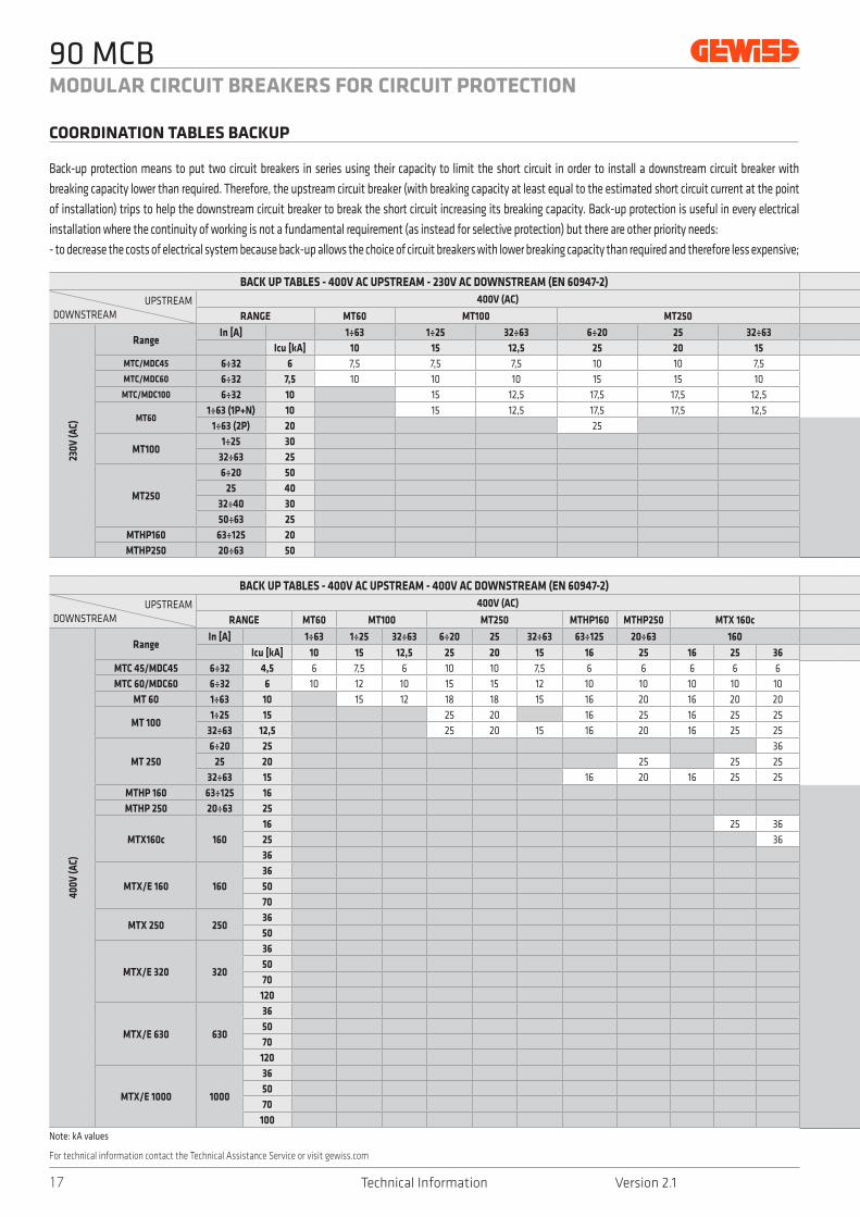
BACK UP TABLES - 400V AC UPSTREAM - 400V AC DOWNSTREAM (EN 60947-2)
UPSTREAMDOWNSTREAM
400V (AC)
RANGE MT60 MT100 MT250 MTHP160 MTHP250 MTX 160c
400V
(AC)
RangeIn [A] 1÷63 1÷25 32÷63 6÷20 25 32÷63 63÷125 20÷63 160
Icu [kA] 10 15 12,5 25 20 15 16 25 16 25 36MTC 45/MDC45 6÷32 4,5 6 7,5 6 10 10 7,5 6 6 6 6 6MTC 60/MDC60 6÷32 6 10 12 10 15 15 12 10 10 10 10 10
MT 60 1÷63 10 15 12 18 18 15 16 20 16 20 20
MT 1001÷25 15 25 20 16 25 16 25 25
32÷63 12,5 25 20 15 16 20 16 25 25
MT 2506÷20 25 36
25 20 25 25 2532÷63 15 16 20 16 25 25
MTHP 160 63÷125 16MTHP 250 20÷63 25
MTX160c 16016 25 3625 3636
MTX/E 160 160365070
MTX 250 2503650
MTX/E 320 320
365070
120
MTX/E 630 630
365070
120
MTX/E 1000 1000
365070
100
BACK UP TABLES - 400V AC UPSTREAM - 230V AC DOWNSTREAM (EN 60947-2)
UPSTREAMDOWNSTREAM
400V (AC)
RANGE MT60 MT100 MT250
230V
(AC)
RangeIn [A] 1÷63 1÷25 32÷63 6÷20 25 32÷63
Icu [kA] 10 15 12,5 25 20 15MTC/MDC45 6÷32 6 7,5 7,5 7,5 10 10 7,5 MTC/MDC60 6÷32 7,5 10 10 10 15 15 10
MTC/MDC100 6÷32 10 15 12,5 17,5 17,5 12,5
MT601÷63 (1P+N) 10 15 12,5 17,5 17,5 12,5
1÷63 (2P) 20 25
MT1001÷25 30
32÷63 25
MT250
6÷20 5025 40
32÷40 3050÷63 25
MTHP160 63÷125 20MTHP250 20÷63 50
Note: kA values
Back-up protection means to put two circuit breakers in series using their capacity to limit the short circuit in order to install a downstream circuit breaker with breaking capacity lower than required. Therefore, the upstream circuit breaker (with breaking capacity at least equal to the estimated short circuit current at the point of installation) trips to help the downstream circuit breaker to break the short circuit increasing its breaking capacity. Back-up protection is useful in every electrical installation where the continuity of working is not a fundamental requirement (as instead for selective protection) but there are other priority needs:- to decrease the costs of electrical system because back-up allows the choice of circuit breakers with lower breaking capacity than required and therefore less expensive;
COORDINATION TABLES BACKUP

90 MCB
18Technical Information Version 2.1
MODULAR CIRCUIT BREAKERS FOR CIRCUIT PROTECTION
For technical information contact the Technical Assistance Service or visit gewiss.com
BACK UP TABLES - 400V AC UPSTREAM - 400V AC DOWNSTREAM (EN 60947-2)400V (AC)
MTX/E 160 MTX 250 MTX/E 320 MTX/E 630 MTX/E 1000 MTSE 1600
160 250 320 630 1000 1600
36 50 70 36 50 36 50 70 120 36 50 70 120 36 50 70 100 50 65 100
10 10 10 10 10 10 1020 20 20 16 16 20 20 20 2025 30 30 25 30 25 25 25 3025 25 25 20 25 25 25 25 3030 36 36 30 30 30 30 30 3030 36 36 25 25 25 30 30 3025 25 30 20 20 20 25 25 2525 25 30 20 20 20 25 25 2530 30 36 30 30 30 30 30 3036 50 70 36 50 30 36 40 50 30 36 40 50 30 36 40 5036 50 70 36 50 36 40 65 85 36 40 65 85 36 50 65 70 50 50 50
50 70 50 50 65 100 50 65 100 50 65 70 50 50 5050 70 50 50 65 100 50 65 100 50 65 85 50 65 85
70 100 70 100 70 85 65 85120 120 85 85
50 50 65 100 50 65 100 50 65 100 50 50 5070 100 70 100 70 100 65
50 65 100 50 65 100 50 65 65 50 50 6570 100 70 100 70 85 65 85
120 120 100 100
50 65 100 50 65 85 50 50 6570 100 70 85 65 85
120 100 100
50 65 70 40 40 5070 85 85
100
BACK UP TABLES - 400V AC UPSTREAM - 230V AC DOWNSTREAM (EN 60947-2)400V (AC)
MTHP160 MTHP250 MTX 160c MTX/E 160 MTX 25063÷125 20÷63 160 160 250
16 25 16 25 36 36 50 70 36 507,5 10 7,5 10 1010 17,5 10 12,5 16 10 16 16 10 16
12,5 20 16 16 16 16 16 16 16 1612,5 20 16 16 16 16 16 16 16 16
25 25 30 25 30 30 25 3036 36 40 50 36 4036 36 40 50 36 40
50 50 5036 36 50 50 36 5036 36 36 50 36 36
25 36 36 25 36
- to limit the size of circuit breakers;- to maintain existing electrical systems even if they are not still suitable to break the new value of short-circuit.The following tables cover the possible combinations between Gewiss circuit breakers range for electrcal networks 230 and 400V in order the specific let-through energy of upstream circuit breaker is not so high to damage the downstream circuit breaker. The numbers give the value of the breaking capacity espressed in kA considering the combination of the two switches selected.

90 MCB
Technical Information Version 2.119
MODULAR CIRCUIT BREAKERS FOR CIRCUIT PROTECTION
For technical information contact the Technical Assistance Service or visit gewiss.com
SELECTIVITY TABLE - 400 Vac UPSTREAM - 400 Vac DOWNSTREAM (EN 60947-2)UPSTREAM
DOWNSTREAMMTX 160c MTXE 160 MTX 250
TM1 SEP/1 TM1
Range Curve In 16 20 25 32 40 50 63 80 100 125 160 10 25 63 100 160 63 80 100 125 160
MTC
45
MDC
45
C
6 T T T T T T T T T T T T T T T T T T T T
10 3 3 3 3 T 5 T T T T T T T T T T T T T
16 3 3 T 4,5 T T T T T T T T T T T T
20 3 3 3,5 T T T T T T T T 5,5 T T T
25 3 3,5 5,5 T T T T T T T 5,5 T T T
32 3 4,5 T T T T T T 4,5 T T T
MTC
60/
100
MDC
60/
100
B/C
6 5,5 5,5 5,5 5,5 5,5 5,5 T T T T T T T T T T T T T T
10 3 3 3 4,5 5 8,5 T T T T T T T 7,5 8,5 T T T
16 3 3 4,5 4,5 7,5 T T T T T T 5 7,5 T T T
20 3 3 3,5 5,5 T T T T T T 5 5,5 T T T
25 3 3,5 5,5 T T T T T T 5 5,5 T T T
32 3 4,5 5,5 T T T T T 4,5 7 T T
MT
60
B/C
1 T T T T T T T T T T T T T T T T T T T T T
2 T T T T T T T T T T T T T T T T T T T T T
3 T T T T T T T T T T T T T T T T T T T T T
4 T T T T T T T T T T T T T T T T T T T T T
6 5,5 5,5 5,5 5,5 5,5 5,5 T T T T T T T T T T T T T T
10 3 3 3 4,5 5,5 8,5 T T T T T T T 7,5 8,5 T T T
16 3 4,5 4,5 7,5 T T T T T T 5 7,5 T T T
20 3 3,5 5,5 7,5 T T T T T 5 5,5 T T T
25 3,5 5,5 7,5 T T T T T 5 5,5 T T T
32 4,5 7 T T T T T 4,5 7 T T
40 7 T T T T 7 T T
50 6 T T T 6 T
63 T T T
MT
60
D
6 5,5 5,5 5,5 5,5 5,5 5,5 T T T T T T T T T T T T T T
10 3 3 3 3 5 7 T T T T T T T 5 8,5 T T T
16 2 2 3 5 8 T T T T T 3 5 8 T T
20 2 3 4,5 6,5 T T T T T 3 4,5 6,5 T T
25 2,5 4 6 8 T T T T 2,5 4 6 9,5 T
32 4 6 8 T T T T 4 6 9,5 T
40 5 8 T T T 5 8 T
MT
100
B/C
6 5,5 5,5 5,5 5,5 5,5 5,5 10,5 T T T T T T T T 10,5 T T T T
10 3 3 3 3 5,5 8,5 T T T T T T T 7,5 8,5 T T T
16 3 3 4,5 7,5 12 T T T T T 5 7,5 12 T T
20 2,5 3,5 5,5 7,5 T T T T T 5 5,5 8 T T
25 3,5 5,5 7,5 T T T T T 5 5,5 8 T T
32 4,5 7 12 T T T T 4,5 7 12 T
40 7 12 T T T 7 12 T
50 6 10,5 10,5 10,5 6 10,5
63 10,5 10,5 10,5
MT
100
D
6 5,5 5,5 5,5 5,5 5,5 5,5 10,5 T T T T T T T T 10,5 T T T T
10 3 3 3 3 5 8,5 T T T T T T T 5 8,5 T T T
16 2 2 3 5 8 13,5 T T T T 3 5 8 13,5 T
20 2 3 4,5 6,5 11 T T T T 3 4,5 6,5 11 T
25 2,5 4 6 9,5 T T T T 2,5 4 6 9,5 T
32 4 6 9,5 T T T T 4 6 9,5 T
40 5 8 T T T 5 8 T
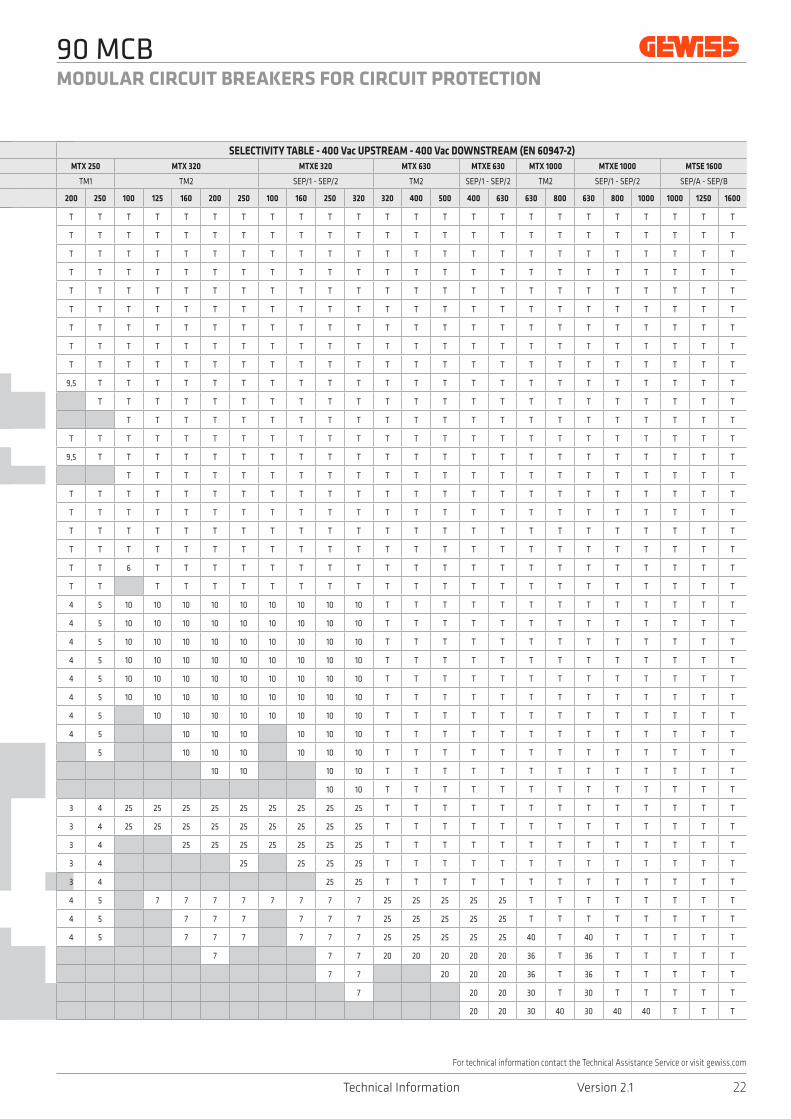
Note: T= total selectivity - kA values
The following tables show the energy selectivity type combination between each circuit breaker belonging to the Gewiss range. The energy selectivity type, as other types, has the aim to ensure maximum continuity of working, even in the case of fault, suppling only the electrical circuits without fault and tripping the circuit breakers of fault circuits. This coordination requires the upstream circuit breaker is dimensioned enough to let pass the fault current for a time as long as necessary the downstream circuit breaker trips. The energy selectivity can be of two types:
SELECTIVITY TABLES

90 MCB
20Technical Information Version 2.1
MODULAR CIRCUIT BREAKERS FOR CIRCUIT PROTECTION
For technical information contact the Technical Assistance Service or visit gewiss.com
SELECTIVITY TABLE - 400 Vac UPSTREAM - 400 Vac DOWNSTREAM (EN 60947-2)MTX 250 MTX 320 MTXE 320 MTX 630 MTXE 630 MTX 1000 MTXE 1000 MTSE 1600
TM1 TM2 SEP/1 - SEP/2 TM2 SEP/1 - SEP/2 TM2 SEP/1 - SEP/2 SEP/A - SEP/B
200 250 100 125 160 200 250 100 160 250 320 320 400 500 400 630 630 800 630 800 1000 1000 1250 1600
T T T T T T T T T T T T T T T T T T T T T T T T
T T T T T T T T T T T T T T T T T T T T T T T T
T T T T T T T T T T T T T T T T T T T T T T T T
T T T T T T T T T T T T T T T T T T T T T T T T
T T T T T T T T T T T T T T T T T T T T T T T T
T T T T T T T T T T T T T T T T T T T T T T T T
T T T T T T T T T T T T T T T T T T T T T T T T
T T T T T T T T T T T T T T T T T T T T T T T T
T T T T T T T T T T T T T T T T T T T T T T T T
T T T T T T T T T T T T T T T T T T T T T T T T
T T T T T T T T T T T T T T T T T T T T T T T T
T T T T T T T T T T T T T T T T T T T T T T T T
T T T T T T T T T T T T T T T T T T T T T T T T
T T T T T T T T T T T T T T T T T T T T T T T T
T T T T T T T T T T T T T T T T T T T T T T T T
T T T T T T T T T T T T T T T T T T T T T T T T
T T T T T T T T T T T T T T T T T T T T T T T T
T T T T T T T T T T T T T T T T T T T T T T T T
T T T T T T T T T T T T T T T T T T T T T T T T
T T T T T T T T T T T T T T T T T T T T T T T T
T T T T T T T T T T T T T T T T T T T T T T T T
T T T T T T T T T T T T T T T T T T T T T T T T
T T T T T T T T T T T T T T T T T T T T T T T T
T T T T T T T T T T T T T T T T T T T T T T T T
T T T T T T T T T T T T T T T T T T T T T T T T
T T T T T T T T T T T T T T T T T T T T T T T T
T T T T T T T T T T T T T T T T T T T T T T T T
T T T T T T T T T T T T T T T T T T T T T T T T
T T T T T T T T T T T T T T T T T T T T T T T T
T T T T T T T T T T T T T T T T T T T T T T T T
T T T T T T T T T T T T T T T T T T T T T T T T
T T T T T T T T T T T T T T T T T T T T T T T T
T T T T T T T T T T T T T T T T T T T T T T T T
T T T T T T T T T T T T T T T T T T T T T T T T
T T T T T T T T T T T T T T T T T T T T T T T T
T T T T T T T T T T T T T T T T T T T T T T T T
T T T T T T T T T T T T T T T T T T T T T T T T
T T T T T T T T T T T T T T T T T T T T T T T T
T T T T T T T T T T T T T T T T T T T T T T T T
T T T T T T T T T T T T T T T T T T T T T T T T
T T T T T T T T T T T T T T T T T T T T T T T T
T T T T T T T T T T T T T T T T T T T T T T T T
T T T T T T T T T T T T T T T T T T T T T T T T
T T T T T T T T T T T T T T T T T T T T T T T T
T T T T T T T T T T T T T T T T T T T T T T T T
T T T T T T T T T T T T T T T T T T T T T T T T
T T T T T T T T T T T T T T T T T T T T T T T T
T T T T T T T T T T T T T T T T T T T T T T T T
- PARTIAL: in case of short circuit, the tripping of the circuit breaker of fault circuit is guaranteed up to the value of the short circuit current expressed in kA, given in the table, depending on the selected circuit breaker. Above this value the selectivity is not ensured because the upstream circuit breaker can trip to cut off power to the electrical system.- TOTAL: in case of short circuit, the tripping of circuit-breaker of fault circuit is always guaranteed. This situation is indicated with a letter T in the table. The energy selectivity type is useful if it is not possible to set a time delay (time selectivity time) and it is based on the comparison between the two let-through energy characteristics (I2t) of the two circuit breakers put in series. The two let-through energy characteristics must not have intersection points to obtain total selectivity.

90 MCB
Technical Information Version 2.121
MODULAR CIRCUIT BREAKERS FOR CIRCUIT PROTECTION
For technical information contact the Technical Assistance Service or visit gewiss.com
SELECTIVITY TABLE - 400 Vac UPSTREAM - 400 Vac DOWNSTREAM (EN 60947-2)UPSTREAM
DOWNSTREAMMTX 160c MTXE 160 MTX 250
TM1 SEP/1 TM1
Range Curve In 16 20 25 32 40 50 63 80 100 125 160 10 25 63 100 160 63 80 100 125 160
MT
250
C
6 5,5 5,5 5,5 5,5 5,5 5,5 10,5 T T T T T T T T 10,5 T T T T
10 3 3 3 3 3 5,5 8,5 T T T T T T T 7,5 8,5 T T T
16 3 3 4,5 7,5 12 T T T T T 5 7,5 12 T T
20 2,5 3,5 5,5 7,5 T T T T T 5 5,5 8 T T
25 3,5 5,5 7,5 T T T T T 5 5,5 8 T T
32 4,5 7 12 T T T T 4,5 7 12 T
40 7 12 T T T 7 12 T
50 6 10,5 10,5 10,5 6 10,5
63 10,5 10,5 10,5
MTH
P 16
0
C
80 6 6
100
125
MTH
P 16
0
D
80 6 7,5 7,5 9,5
100 6 6
125
MTH
P 25
0
C
20 5,5 5,5 T T T T T T T T 2,5 5,5 8 T T
25 3,5 5,5 7,5 T T 3,5 7,5 T 5 8 T T
32 4,5 7 T T 7 T 4,5 7 T T
40 7 T T 7 T 7 T T
50 6 T T 6 T
63 T T 10
MTX
160c
16 3 3 3 3 3
20 3 3 3 3 3
25 3 3 3 3 3
32 3 3 3 3
40 3 3 3 3
50 3 3 3 3
63 3 3 3
80 3
100
125
160
MTX
E 16
0
10
25
63
100
160
MTX
250
63 3
80 3
100
125
160
200
250
Note: T= total selectivity - kA values
SELECTIVITY TABLES
90 MCB
22Technical Information Version 2.1
MODULAR CIRCUIT BREAKERS FOR CIRCUIT PROTECTION
For technical information contact the Technical Assistance Service or visit gewiss.com
SELECTIVITY TABLE - 400 Vac UPSTREAM - 400 Vac DOWNSTREAM (EN 60947-2)MTX 250 MTX 320 MTXE 320 MTX 630 MTXE 630 MTX 1000 MTXE 1000 MTSE 1600
TM1 TM2 SEP/1 - SEP/2 TM2 SEP/1 - SEP/2 TM2 SEP/1 - SEP/2 SEP/A - SEP/B
200 250 100 125 160 200 250 100 160 250 320 320 400 500 400 630 630 800 630 800 1000 1000 1250 1600
T T T T T T T T T T T T T T T T T T T T T T T T
T T T T T T T T T T T T T T T T T T T T T T T T
T T T T T T T T T T T T T T T T T T T T T T T T
T T T T T T T T T T T T T T T T T T T T T T T T
T T T T T T T T T T T T T T T T T T T T T T T T
T T T T T T T T T T T T T T T T T T T T T T T T
T T T T T T T T T T T T T T T T T T T T T T T T
T T T T T T T T T T T T T T T T T T T T T T T T
T T T T T T T T T T T T T T T T T T T T T T T T
9,5 T T T T T T T T T T T T T T T T T T T T T T T
T T T T T T T T T T T T T T T T T T T T T T T
T T T T T T T T T T T T T T T T T T T T T T
T T T T T T T T T T T T T T T T T T T T T T T T
9,5 T T T T T T T T T T T T T T T T T T T T T T T
T T T T T T T T T T T T T T T T T T T T T T
T T T T T T T T T T T T T T T T T T T T T T T T
T T T T T T T T T T T T T T T T T T T T T T T T
T T T T T T T T T T T T T T T T T T T T T T T T
T T T T T T T T T T T T T T T T T T T T T T T T
T T 6 T T T T T T T T T T T T T T T T T T T T T
T T T T T T T T T T T T T T T T T T T T T T T
4 5 10 10 10 10 10 10 10 10 10 T T T T T T T T T T T T T
4 5 10 10 10 10 10 10 10 10 10 T T T T T T T T T T T T T
4 5 10 10 10 10 10 10 10 10 10 T T T T T T T T T T T T T
4 5 10 10 10 10 10 10 10 10 10 T T T T T T T T T T T T T
4 5 10 10 10 10 10 10 10 10 10 T T T T T T T T T T T T T
4 5 10 10 10 10 10 10 10 10 10 T T T T T T T T T T T T T
4 5 10 10 10 10 10 10 10 10 T T T T T T T T T T T T T
4 5 10 10 10 10 10 10 T T T T T T T T T T T T T
5 10 10 10 10 10 10 T T T T T T T T T T T T T
10 10 10 10 T T T T T T T T T T T T T
10 10 T T T T T T T T T T T T T
3 4 25 25 25 25 25 25 25 25 25 T T T T T T T T T T T T T
3 4 25 25 25 25 25 25 25 25 25 T T T T T T T T T T T T T
3 4 25 25 25 25 25 25 25 T T T T T T T T T T T T T
3 4 25 25 25 25 T T T T T T T T T T T T T
3 4 25 25 T T T T T T T T T T T T T
4 5 7 7 7 7 7 7 7 7 25 25 25 25 25 T T T T T T T T
4 5 7 7 7 7 7 7 25 25 25 25 25 T T T T T T T T
4 5 7 7 7 7 7 7 25 25 25 25 25 40 T 40 T T T T T
7 7 7 20 20 20 20 20 36 T 36 T T T T T
7 7 20 20 20 36 T 36 T T T T T
7 20 20 30 T 30 T T T T T
20 20 30 40 30 40 40 T T T

90 MCB
Technical Information Version 2.123
MODULAR CIRCUIT BREAKERS FOR CIRCUIT PROTECTION
For technical information contact the Technical Assistance Service or visit gewiss.com
Protection of lighting circuitsDetermining the rated current of the circuit breakerTo select the most suitable rated current of the miniature circuit breaker for lighting circuit protection, it is necessary to know the operating current provided by the lighting device manufacturer, or calculated on the basis of the type of lamp and the relative technical data (rated power, power supply voltage and power factor). Once the operating current is known, you should choose the circuit breaker version with the rated current value immediately above this value. The tables below show the maximum number of lamps that can be protected, on the basis of the rated current. For all case, you are advised to choose a circuit breaker with tripping characteristic C.
SINGLE-PHASE 230V AC - THREE-PHASE DISTRIBUTION 400V AC WITH NEUTRAL (1)
Rated current In (A): 6 10 13 16 20 25 32 40 50 63 80 100 125
FLUORESCENT lampsLamp
power (W)Number of lamps per phase
Single without P.F. correction
(cosφ = 0.6)
18 24 36 61 79 98 122 153 196 245 306 386 490 613
36 12 18 30 39 49 61 76 98 122 153 193 245 306
58 7 11 19 24 30 38 47 60 76 95 119 152 190
Single with P.F. correction
(cosφ = 0.86) (2)
18 35 52 87 114 140 175 219 281 351 439 553 703 879
36 17 26 43 57 70 87 109 140 175 219 276 351 439
58 10 16 27 35 43 54 68 87 109 136 171 218 272
Double with P.F. correction
(cosφ = 0.86) (2)
2 x 18 17 26 43 57 70 87 109 140 175 219 276 351 439
2 x 36 8 13 21 28 35 43 54 70 87 109 138 175 219
2 x 58 5 8 13 17 21 27 34 43 54 68 85 109 136(1) Star connection (2) The values given are valid for lamps with inductive ballast and starter. In the case of lamps with an electronic power supply, the number of lamps indicated should be halved
THREE-PHASE DISTRIBUTION 230V AC and 400V AC (3)
DISCHARGE lamps Power (W) (4) Current In (A)
Mercury vapor lamp
≤ 700 6
≤ 1000 10
≤ 2000 16
Metal halide lamp
≤ 375 6
≤ 1000 10
≤ 2000 16
High pressure sodium vapor lamp≤ 400 6
≤ 1000 10(3) With ballast with or without P.F. correction, and star or delta connection (4) The values given refer to the maximum values for each start-up
SINGLE PHASE DISTRIBUTION 230 V a.c.Tripping characteristic C
Rated current In (A) 6 10 13 16 20 25 32 40 50 63 80 100 125SMART LED lamps Lamp power (W) Number lamps per phase
SMAR
T [4
] - L
B
2L 31 - 10 17 23 32 44 59 78 100 129 168 214 270
2+2L 62 - 6 10 14 19 26 35 46 59 76 99 126 159
4L 62 - 6 10 14 19 26 35 46 59 76 99 126 159
5L 69 - 4 7 10 14 19 26 34 44 57 74 94 119
SMAR
T [4
] - H
B
4+4L 124 - 3 5 7 9 13 17 23 29 38 49 63 79
5+5L 138 - 2 3 5 7 9 13 17 22 28 37 47 59
4x4L 248 - 1 2 3 4 6 8 11 14 19 24 31 39
4x5L 276 - - 1 2 3 4 6 8 11 14 18 23 29
90 MCB
24Technical Information Version 2.1
MODULAR CIRCUIT BREAKERS FOR CIRCUIT PROTECTION
For technical information contact the Technical Assistance Service or visit gewiss.com
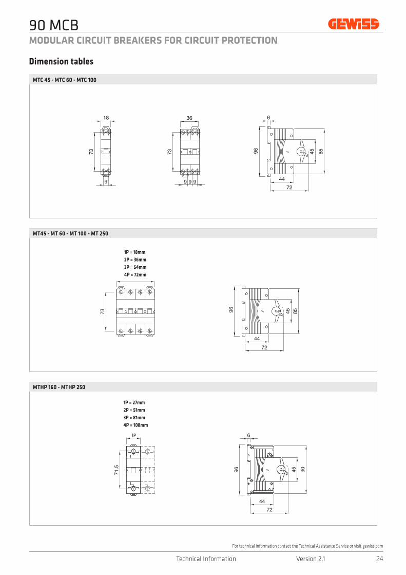
MTC 45 - MTC 60 - MTC 100
MT45 - MT 60 - MT 100 - MT 250
MTHP 160 - MTHP 250
Dimension tables
72 7272
72 72
IP
72
71.5
IP
72
71.5
1P = 18mm2P = 36mm3P = 54mm4P = 72mm
1P = 27mm2P = 51mm3P = 81mm4P = 108mm
![Te rms & Conditions for Your Ca d P otection Membership ... · PDF fileTe rms & Conditions for Your Ca d P otection Membership – Classic [Single] Definitions Abroad Agreement Card](https://img.pdfslide.us/doc/110x75/5ab84a487f8b9a28468cad95/te-rms-conditions-for-your-ca-d-p-otection-membership-rms-conditions-for-your.jpg)