Embed Size (px)
Citation preview
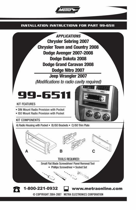
INSTALLATION INSTRUCTIONS FOR PART 99-6511
99-6511
APPLICATIONSChrysler Sebring 2007
Chrysler Town and Country 2008Dodge Avenger 2007-2008
Dodge Dakota 2008Dodge Grand Caravan 2008
Dodge Nitro 2007Jeep Wrangler 2007
(Modifications to radio cavity required)
KIT FEATURES
• DIN Mount Radio Provision with Pocket• ISO Mount Radio Provision with Pocket
A) Radio Housing with Pocket • B) ISO Brackets • C) ISO Trim Plate
KIT COMPONENTS
A
TOOLS REQUIRED:Small Flat Blade Screwdriver/ Panel Removal Tool
• Phillips Screwdriver • Socket Set
1-800-221-0932 © COPYRIGHT 2004-2007 METRA ELECTRONICS CORPORATION
www.metraonline.com
B C
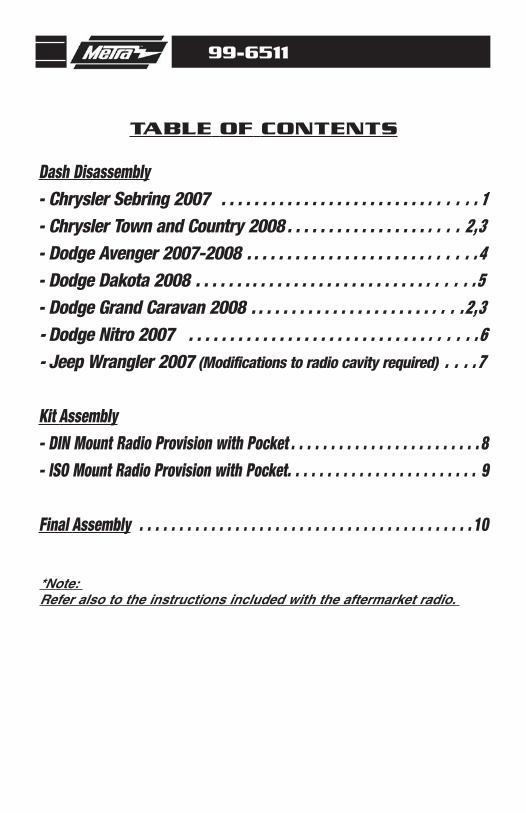
Dash Disassembly- Chrysler Sebring 2007 . . . . . . . . . . . . . . . . . . . . . . . . . . . . . . . 1- Chrysler Town and Country 2008 . . . . . . . . . . . . . . . . . . . . . 2,3- Dodge Avenger 2007-2008 . . . . . . . . . . . . . . . . . . . . . . . . . . . .4- Dodge Dakota 2008 . . . . . . . . . . . . . . . . . . . . . . . . . . . . . . . . . .5- Dodge Grand Caravan 2008 . . . . . . . . . . . . . . . . . . . . . . . . . .2,3- Dodge Nitro 2007 . . . . . . . . . . . . . . . . . . . . . . . . . . . . . . . . . . .6- Jeep Wrangler 2007 (Modifications to radio cavity required) . . . .7
Kit Assembly- DIN Mount Radio Provision with Pocket . . . . . . . . . . . . . . . . . . . . . . . . 8- ISO Mount Radio Provision with Pocket. . . . . . . . . . . . . . . . . . . . . . . . 9
Final Assembly . . . . . . . . . . . . . . . . . . . . . . . . . . . . . . . . . . . . . . . . . . 10
TABLE OF CONTENTS
99-6511
*Note: Refer also to the instructions included with the aftermarket radio.
99-6511 DASH DISASSEMBLY
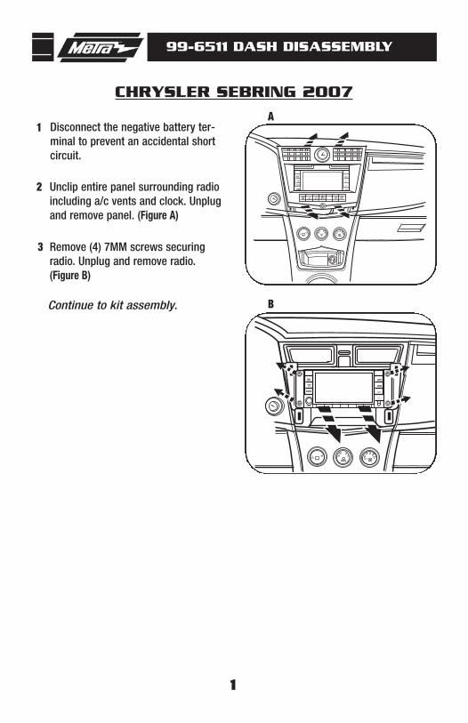
CHRYSLER SEBRING 2007A
B
1
1
Remove (4) 7MM screws securingradio. Unplug and remove radio.(Figure B)
Disconnect the negative battery ter-minal to prevent an accidental shortcircuit.
3
Unclip entire panel surrounding radioincluding a/c vents and clock. Unplugand remove panel. (Figure A)
2
Continue to kit assembly.
99-6511 DASH DISASSEMBLY
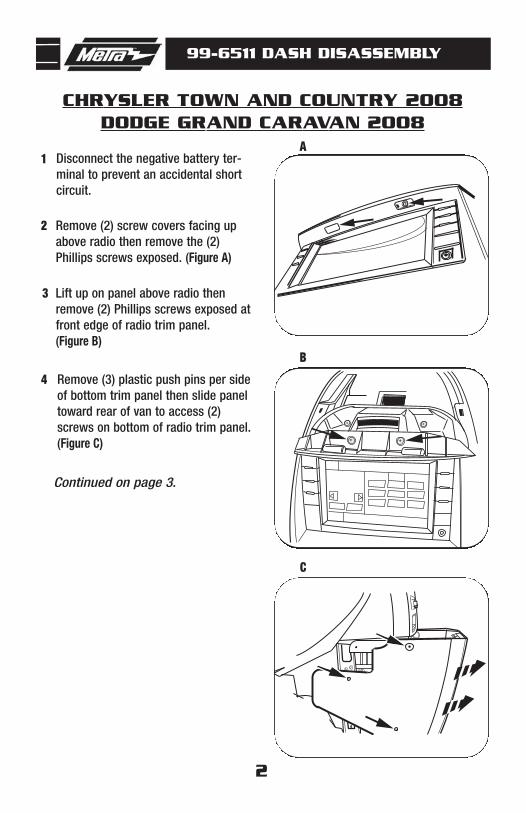
CHRYSLER TOWN AND COUNTRY 2008DODGE GRAND CARAVAN 2008
A
B
C
2
1
Lift up on panel above radio thenremove (2) Phillips screws exposed atfront edge of radio trim panel.(Figure B)
Disconnect the negative battery ter-minal to prevent an accidental shortcircuit.
3
Remove (3) plastic push pins per sideof bottom trim panel then slide paneltoward rear of van to access (2)screws on bottom of radio trim panel.(Figure C)
4
Remove (2) screw covers facing upabove radio then remove the (2)Phillips screws exposed. (Figure A)
2
Continued on page 3.
99-6511 DASH DISASSEMBLY
D
E
1 2 3 4 5 6 AUX
AUX
SET
VOLUME
PUSH ON PUSH AUDIO/SELECTAM
FM
DISC
LIST
MUSICTYPE
SEL;ECT
TUNE/SCROLL
SEEKSEEK SCAN TIME INFO RW FFU
F
3
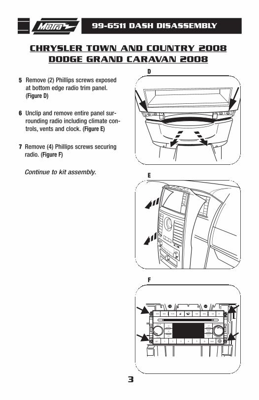
5 Remove (2) Phillips screws exposedat bottom edge radio trim panel.(Figure D)
Remove (4) Phillips screws securingradio. (Figure F)
7
Unclip and remove entire panel sur-rounding radio including climate con-trols, vents and clock. (Figure E)
6
Continue to kit assembly.
CHRYSLER TOWN AND COUNTRY 2008DODGE GRAND CARAVAN 2008
99-6511 DASH DISASSEMBLY
DODGE AVENGER 2007-2008A
B
1 2 3 4 5 6 AUX
AUX
SET
VOLUME
PUSH ON PUSH AUDIO/SELECTAM
FM
DISC
LIST
MUSIC TYPE
SEL;ECT
TUNE/SCROLL
SEEKSEEK SCAN TIME INFO RW FFU
CD
4
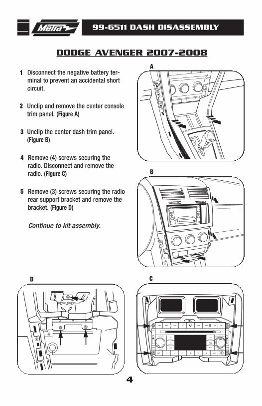
1
Unclip the center dash trim panel.(Figure B)
Disconnect the negative battery ter-minal to prevent an accidental shortcircuit.
3
Remove (4) screws securing theradio. Disconnect and remove theradio. (Figure C)
Remove (3) screws securing the radiorear support bracket and remove thebracket. (Figure D)
4
5
Unclip and remove the center consoletrim panel. (Figure A)
2
Continue to kit assembly.
99-6511 DASH DISASSEMBLY
DODGE DAKOTA 2008A
1 2 3 4 5 6 AUX
AUX
SET
VOLUME
PUSH ON PUSH AUDIO/SELECTAM
FM
DISC
LIST
MUSICTYPE
SEL;ECT
TUNE/SCROLL
SEEKSEEK SCAN TIME INFO RW FFU
B
5
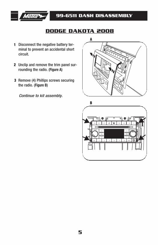
1
Remove (4) Phillips screws securingthe radio. (Figure B)
Disconnect the negative battery ter-minal to prevent an accidental shortcircuit.
3
Unclip and remove the trim panel sur-rounding the radio. (Figure A)
2
Continue to kit assembly.
99-6511 DASH DISASSEMBLY
DODGE NITRO 2007A
61 2 3 4 5
2 3 4 5 61
B
6
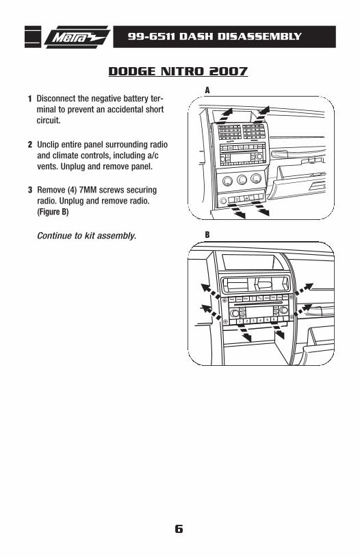
1
Remove (4) 7MM screws securingradio. Unplug and remove radio.(Figure B)
Disconnect the negative battery ter-minal to prevent an accidental shortcircuit.
3
Unclip entire panel surrounding radioand climate controls, including a/cvents. Unplug and remove panel.
2
Continue to kit assembly.
99-6511 DASH DISASSEMBLY
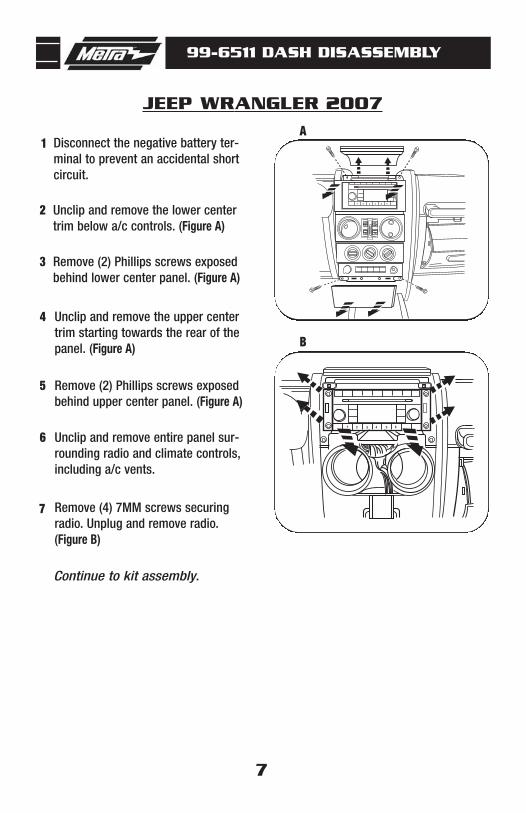
JEEP WRANGLER 2007A
1 2 3 4 5 6
1 2 3 4 5 6
B
7
1
Remove (2) Phillips screws exposedbehind lower center panel. (Figure A)
Disconnect the negative battery ter-minal to prevent an accidental shortcircuit.
3
Unclip and remove the lower centertrim below a/c controls. (Figure A)
2
Remove (2) Phillips screws exposedbehind upper center panel. (Figure A)
5
Unclip and remove entire panel sur-rounding radio and climate controls,including a/c vents.
6
Remove (4) 7MM screws securingradio. Unplug and remove radio.(Figure B)
7
Unclip and remove the upper centertrim starting towards the rear of thepanel. (Figure A)
4
Continue to kit assembly.
99-6511 KIT ASSEMBLY
8
A
B
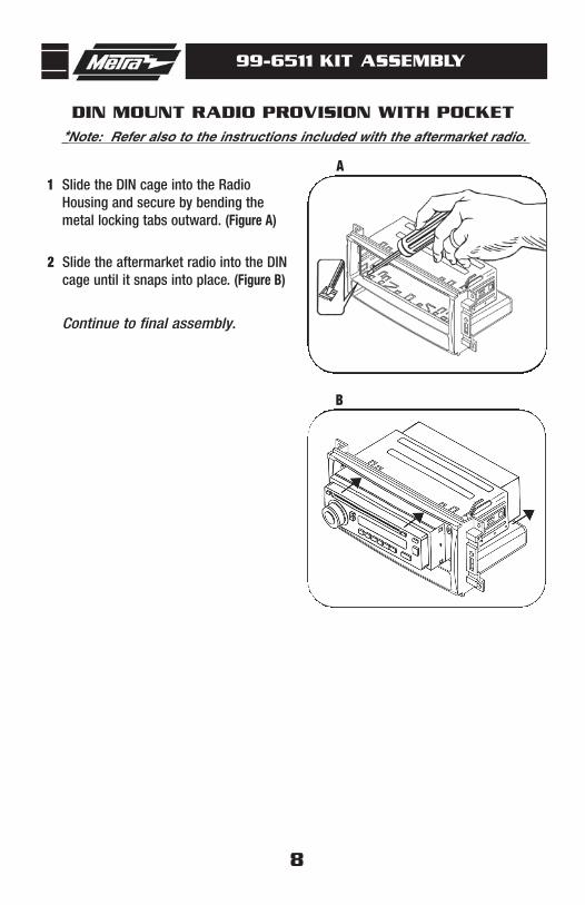
DIN MOUNT RADIO PROVISION WITH POCKET
Slide the DIN cage into the RadioHousing and secure by bending themetal locking tabs outward. (Figure A)
1
Slide the aftermarket radio into the DINcage until it snaps into place. (Figure B)
2
Continue to final assembly.
*Note: Refer also to the instructions included with the aftermarket radio.
99-6511 KIT ASSEMBLY
9
A
B
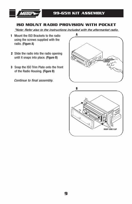
ISO MOUNT RADIO PROVISION WITH POCKET
Mount the ISO Brackets to the radiousing the screws supplied with theradio. (Figure A)
1
Slide the radio into the radio openinguntil it snaps into place. (Figure B)
2
Snap the ISO Trim Plate onto the frontof the Radio Housing. (Figure B)
3
Continue to final assembly.
*Note: Refer also to the instructions included with the aftermarket radio.
99-6511 FINAL ASSEMBLY
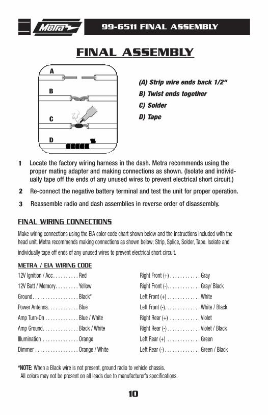
FINAL ASSEMBLY
(A) Strip wire ends back 1/2"
B) Twist ends together
C) Solder
D) Tape
A
B
C
D
Locate the factory wiring harness in the dash. Metra recommends using the proper mating adapter and making connections as shown. (Isolate and individ-ually tape off the ends of any unused wires to prevent electrical short circuit.)
Re-connect the negative battery terminal and test the unit for proper operation.
Reassemble radio and dash assemblies in reverse order of disassembly.
1
2
3
FINAL WIRING CONNECTIONS
Make wiring connections using the EIA color code chart shown below and the instructions included with thehead unit. Metra recommends making connections as shown below; Strip, Splice, Solder, Tape. Isolate and
individually tape off ends of any unused wires to prevent electrical short circuit.
METRA / EIA WIRING CODE
12V Ignition / Acc . . . . . . . . . . Red
12V Batt / Memory. . . . . . . . . Yellow
Ground. . . . . . . . . . . . . . . . . . Black*
Power Antenna. . . . . . . . . . . . Blue
Amp Turn-On . . . . . . . . . . . . . Blue / White
Amp Ground. . . . . . . . . . . . . . Black / White
Illumination . . . . . . . . . . . . . . Orange
Dimmer . . . . . . . . . . . . . . . . . Orange / White
Right Front (+) . . . . . . . . . . . . Gray
Right Front (-). . . . . . . . . . . . . Gray/ Black
Left Front (+) . . . . . . . . . . . . . White
Left Front (-). . . . . . . . . . . . . . White / Black
Right Rear (+) . . . . . . . . . . . . Violet
Right Rear (-) . . . . . . . . . . . . . Violet / Black
Left Rear (+) . . . . . . . . . . . . . Green
Left Rear (-) . . . . . . . . . . . . . . Green / Black
*NOTE: When a Black wire is not present, ground radio to vehicle chassis.All colors may not be present on all leads due to manufacturer’s specifications.
10

NOTES
11
99-6511

NOTES
12
99-6511

NOTES
13
99-6511
99-6511 INSTRUCTIONS
1-800-221-0932 REV. 09/28/07 © COPYRIGHT 2004-2007 METRA ELECTRONICS CORPORATION INST99-6511
www.metraonline.com


![[Concord] [Warrior Series 6511] the Battle of Stalingrad. Russia's Great Patriotic War (2004)](https://img.pdfslide.us/doc/110x75/55cf9b0b550346d033a48252/concord-warrior-series-6511-the-battle-of-stalingrad-russias-great.jpg)


![[armor] 6511 The Battle of Stalingrad - Russia's Great Patriotic War [Concord]](https://img.pdfslide.us/doc/110x75/5472f1dbb4af9f273d8b458f/armor-6511-the-battle-of-stalingrad-russias-great-patriotic-war-concord.jpg)
![6511 the Battle of Stalingrad - Russia's Great Patriotic War [Concord]](https://img.pdfslide.us/doc/110x75/54488fb2b1af9f2f3d8b4b6a/6511-the-battle-of-stalingrad-russias-great-patriotic-war-concord.jpg)