Embed Size (px)
Citation preview
DESCRIPTIONThe T32 1/32 DIN PID Controller accepts signals from a variety of
temperature sensors (thermocouple or RTD elements), 0-20 mA or 0-50 mVprocess inputs. The controller will precisely display the process value andprovide an accurate control output to maintain the process at the desiredsetpoint. The controller’s comprehensive programming allows it to meet a widevariety of application requirements.
The controller operates in the PID Control mode for heating or cooling, withon-demand auto-tune that automatically establishes the PID constants. ThesePID constants may be fine tuned by the operator at any time. The controlleremploys an overshoot suppression feature that allows for quick response withminimal overshoot. The controller can also be programmed to operate in theOn/Off Control mode with adjustable hysteresis.
The 4-digit display allows viewing of the process variable. Front panelindicators show the status of the outputs and auto-tune. The four front panelkeys are used to program the parameters, change the setpoint, or view theconfigurations. A security pass code is used to lock-out configuration changes.
The alarm output can be configured to activate according to a variety ofactions. These actions include: Sensor Break, Absolute HI or LO, Deviation HIor LO, or Band Inside or Outside. The main control output can be configured asan alarm output for Absolute HI or LO actions.
The controller is constructed of a lightweight, high impact plastic case witha tinted front panel. The small size allows for installation in tight areas. Therugged design of the T32 makes it extremely reliable in industrial environments.
SAFETY SUMMARYAll safety related regulations, local codes and instructions that appear in the
manual or on equipment must be observed to ensure personal safety and toprevent damage to either the instrument or equipment connected to it. Ifequipment is used in a manner not specified by the manufacturer, the protectionprovided by the equipment may be impaired.
Do not use the unit to directly command motors, valves, or other actuatorsnot equipped with safeguards. To do so can be potentially harmful to persons orequipment in the event of a fault to the unit. An independent and redundanttemperature limit indicator with alarms is strongly recommended. Theindicators should have input sensors and AC power feeds independent fromother equipment.
ORDERING INFORMATION
SPECIFICATIONS1. DISPLAY :
Main: Single 4-digit 0.38” (9.65 mm) green LEDDisplay Messages:
“----” - Appears when input is higher than range.“----” - Appears when input is lower than range.“ConF” - Appears with incorrect configuration code,
with this message the outputs will not work.Status Annunciators:
1 - OP1 or AL1 is active2 - AL2 is active
AT - Auto Tune is active2. POWER: 85 VAC min. to 250 VAC max., 48 to 63 Hz 2 VA max.
Isolation: 2500 Vrms, 1 minute.3. CONTROLS:
Four front panel push buttons for modification and configuration ofcontroller functions.
4. MEMORY : Nonvolatile memory stores all parameter values.
1
l COMPACT IN SIZE
l ACCEPTS THERMOCOUPLE, RTD, 0-20 mA, 0-50 mV INPUTS
l PID CONTROL WITH OVERSHOOT SUPPRESSION
l ON DEMAND AUTO-TUNING OF PID CONTROL SETTINGS
l STATUS INDICATORS FOR OUTPUTS
l REMOVABLE FRONT PANEL ASSEMBLY
l PARAMETER SECURITY
MODEL T32 - 1/32 DIN PID CONTROLLER
MODEL DESCRIPTION PART NUMBER
T32 1/32 Din PID Controller T3200000
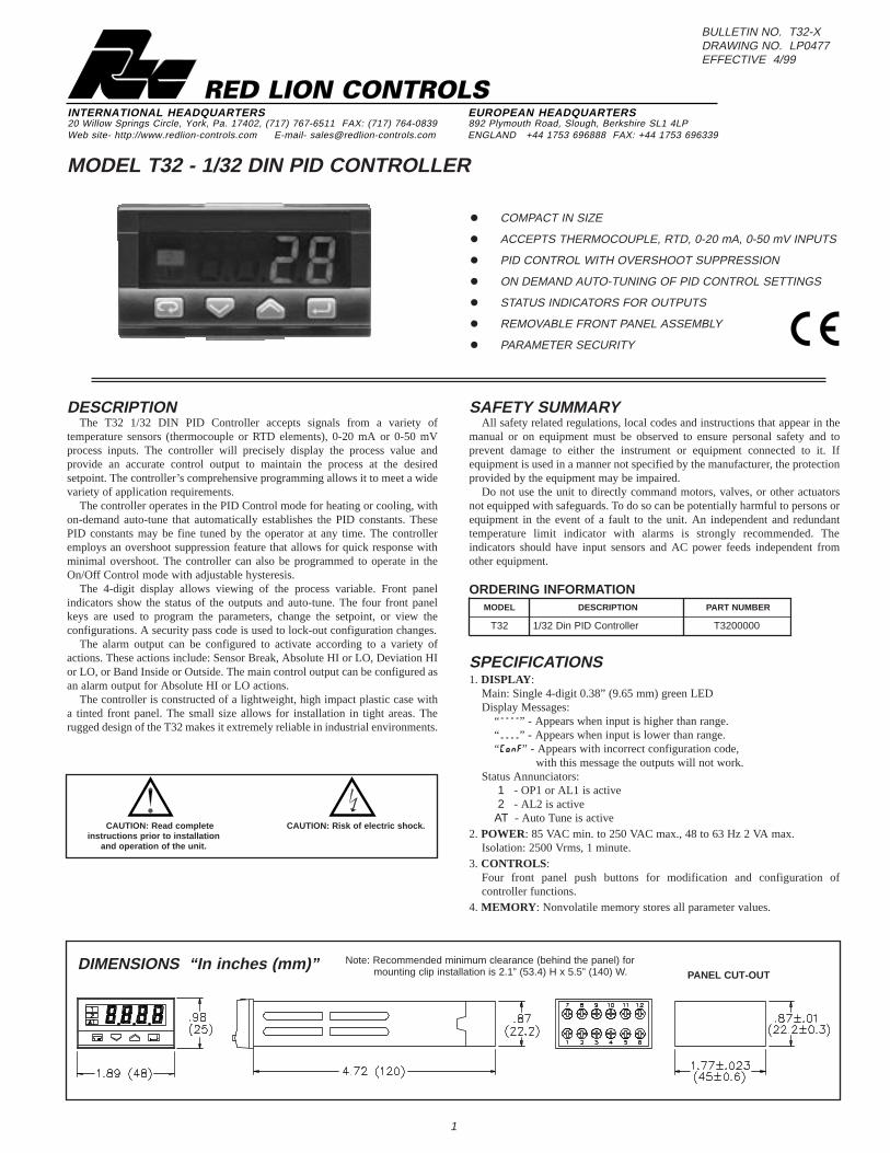
DIMENSIONS “In inches (mm)” Note: Recommended minimum clearance (behind the panel) formounting clip installation is 2.1” (53.4) H x 5.5” (140) W. PANEL CUT-OUT
INTERNATIONAL HEADQUARTERS EUROPEAN HEADQUARTERS20 Willow Springs Circle, York, Pa. 17402, (717) 767-6511 FAX: (717) 764-0839 892 Plymouth Road, Slough, Berkshire SL1 4LPWeb site- http://www.redlion-controls.com E-mail- [email protected] ENGLAND +44 1753 696888 FAX: +44 1753 696339
RED LION CONTROLS
BULLETIN NO. T32-XDRAWING NO. LP0477EFFECTIVE 4/99
CAUTION: Read completeinstructions prior to installation
and operation of the unit.
CAUTION: Risk of electric shock.

5. MAIN SENSOR INPUT :Sample Period: 500 msec.Failed Sensor Response:
Display: “- - - -”Control Output: programmable 0% or 100%Alarm 2: High acting turn on, low acting turn offSensor Break Alarm: AL2 programmable to turn on
6. THERMOCOUPLE INPUT :Types: L, J, T, K, S, and Linear mV, software programmableLead resistance effect:< 5 µV / 10 W Wire Res.Cold junction compensation: < 2 mV / °C Env. Temp.Resolution: 1° for all types, except linear mV.
7. RTD INPUT : 2 or 3 wire, 100 ohm platinum, alpha =.00385Resolution: 1° or 0.1°.Lead resistance: 20 W max. per leadLead resistance effect: < 0.5 °C / 10 W Wire Res.Temperature effect: 0.1 °C / 10 °C Env. Temp.
8. PROCESS INPUT:
Input Drift: <0.1% / 20°CScaleable: -999....9999 (min. range of 100 digits)Current input: utilizes external 2.5W resistor (included)
9. INDICA TION ACCURACY : 0.25% ± 1 digit for temperature input0.1 % ± 1 digit for process input
10. OUTPUTS:The controller has one Relay output and one Logic / SSR output. Eitheroutput type can be programmed to perform the Ouput Control 1 (Alarm 1)function. The remaining output type then assumes the Alarm 2 function. Thisis done through the Configuration Code.Relay Output:
Type: Form A Normally Open (NO)Contact Rating: 2 A @ 250 VAC (resistive load)
Logic / SSR Output:Rating: 5 VDC ± 10% @ 30 mA (not isolated)
11. MAIN CONTROL :Control: PID (Time Proportioning) or ON/OFFAction: Reverse (heat) or Direct (cool)Cycle time: 1 to 200 sec.Auto-tune: When selected, sets proportional band, integral time and
derivative time values12. ALARMS MODES :
The Main Control Output (OP1) can be configured as Alarm 1 (AL1). Themain alarm is always Alarm 2 (AL2).Reset Action: Automatic onlyHysteresis: ProgrammableAlarm #1 Modes:
Active High with sensor break on or offActive Low with sensor break on or off
Alarm #2 Modes:DisabledSensor Break (on at break)Active High or LowDeviation High or Low *Band Inside or Outside *
* Only available with single alarm configurations.13. ENVIRONMENT AL CONDITIONS :
Operating Range: 0 to 50°COperating Humidity: 5 to 95% max. relative humidity (non-condensing)Altitude: up to 2000 meters
14. CERTIFICA TIONS AND COMPLIANCES :EMC Emissions:
Meets EN 50081-2: Industrial EnvironmentEMC Immunity:
Meets EN 50082-2: Industrial EnvironmentElectrical Safety:
Meets EN 61010-1: Installation Category II, Pollution Degree 215. CONNECTION : Wire clamping screw terminals16. CONSTRUCTION :
IP20 terminal blockIP65 front panel
17. WEIGHT : 0.25 lb (110 g.)
2
INPUT RANGE RESOLUTION
4 mA
0 - 50 mV 10 - 50 mV 10 mV
4 - 20 mA 0 - 20 mA
TC TYPE DISPLAY RANGEWIRE COLOR
ANSI BS 1843 DIN47310
L 0 to +600 °C32 to +1112 °F NA NA red (+)
blue (-)
J 0 to +600 °C32 to +1112 °F
white (+) red (-)
yellow(+) blue (-) NA
T -200 to +400 °C-328 to +752 °F
blue (+) red (-)
white (+) blue (-) NA
K 0 to +1200 °C32 to +2192 °F
yellow(+) red (-)
brown (+) blue (-) NA
S 0 to +1600 °C32 to + 2912 °F
black (+) red (-)
white (+) blue (-) NA
mV scaleable NA NA NA
RTD TYPE RANGE
alpha =.00385 -99.9 to +100.0 °C -147.8 to +212.0 °F
alpha =.00385 -200 to +400 °C -328 to +752 °F
1.0 INSTALLING THE CONTROLLERInstallation
The T32 controller meets IP65 requirements for indooruse when properly installed. The controller isintended to be mounted into an enclosedpanel. Prepare the panel cutout.Remove the mountingclamps from the controllerby inserting a screwdriverbehind the clamps. Verifythat a panel gasket is inback of the bezel. Insertthe controller into thepanel cutout. Position themounting clamps onto thecontroller. Push the mounting clampstightly towards the panel surface.
Installation EnvironmentThe controller should be installed in a location that does not exceed the
maximum operating temperature and provides good air circulation. Placing thecontroller near devices that generate excessive heat should be avoided. Thebezel should be cleaned only with a soft cloth and neutral soap product. Do notuse solvents. Continuous exposure to direct sunlight may accelerate the aging
process of the bezel. Do not use tools of any kind (screwdrivers, pens,pencils, etc.) to operate the keypad of the controller.

WIRING OVERVIEWElectrical connections are made via screw-clamp terminals located on the
back of the meter. All conductors should conform to the meter’s voltage andcurrent ratings. All cabling should conform to appropriate standards of goodinstallation, local codes and regulations. It is recommended that power suppliedto the meter (DC or AC) be protected by a fuse or circuit breaker.
When wiring the meter, compare the numbers embossed on the back of themeter case against those shown in wiring drawings for proper wire position.Strip the wire, leaving approximately 0.3” (7.5 mm) bare lead exposed (strandedwires should be tinned with solder). Insert the lead under the correct screw-clamp terminal and tighten until the wire is secure. (Pull wire to verifytightness.) Each terminal can accept wire sizes from #22 AWG to #16 AWG(0.5 mm to 1.5 mm).
EMC INSTALLA TION GUIDELINESAlthough this unit is designed with a high degree of immunity to Electro
Magnetic Interference (EMI), proper installation and wiring methods must befollowed to ensure compatibility in each application. The type of the electricalnoise, source or coupling method into the unit may be different for variousinstallations. Cable length, routing, and shield termination are very importantand can mean the difference between a successful or troublesome installation.
Listed below are some EMC guidelines for successful installation in anindustrial environment.1. The controller should be mounted in a metal enclosure, that is properly
connected to protective earth.2. Use shielded (screened) cables for all Signal and Control inputs. The shield
(screen) pigtail connection should be made as short as possible. Theconnection point for the shield depends somewhat upon the application.Listed below are the recommended methods of connecting the shield, in orderof their effectiveness.a. Connect the shield only at the panel where the unit is mounted to earth
ground (protective earth).b. Connect the shield to earth ground at both ends of the cable, usually when
the noise source frequency is above 1 MHz.
c. Connect the shield to common of the unit and leave the other end of theshield unconnected and insulated from earth ground.
3. Never run Signal or Control cables in the same conduit or raceway with ACpower lines, conductors feeding motors, solenoids, SCR controls, andheaters, etc. The cables should be run in metal conduit that is properlygrounded. This is especially useful in applications where cable runs are longand portable two-way radios are used in close proximity or if the installationis near a commercial radio transmitter.
4. Signal or Control cables within an enclosure should be routed as far away aspossible from contactors, control relays, transformers, and other noisycomponents.
5. In extremely high EMI environments, the use of external EMI suppressiondevices, such as ferrite suppression cores, is effective. Install them on Signaland Control cables as close to the unit as possible. Loop the cable through thecore several times or use multiple cores on each cable for additionalprotection. Install line filters on the power input cable to the unit to suppresspower line interference. Install them near the power entry point of theenclosure. The following EMI suppression devices (or equivalent) arerecommended:Ferrite Suppression Cores for signal and control cables:
Fair-Rite # 0443167251 (RLC # FCOR0000)TDK # ZCAT3035-1330ASteward # 28B209-0A0
Line Filters for input power cables:Schaffner # FN610-1/07 (RLC # LFIL0000)Schaffner # FN670-1.8/07Corcom # 1 VR3
Note: Reference manufacturer’s instructions when installing a line filter.6. Long cable runs are more susceptible to EMI pickup than short cable runs.
Therefore, keep cable runs as short as possible.7. Switching of inductive loads produces high EMI. Use of snubbers across
inductive loads suppresses EMI.Snubbers:
RLC #SNUB0000
3
2.0 WIRING THE CONTROLLER
Removing the Mounting ClipsInsert a screwdriver behind the clips as
shown. Rotate the screwdriver until theclips release.
Controller SpacingThe design of the controller allows for close spacing of
multiple units. Units can be spaced either horizontally orvertically. The minimum spacing from center line to centerline of units for horizontal installation is 2.56” ( 65 mm).The spacing for vertical installationed is 1.65” (42 mm)from center line to center line.Note: When closely spacing multiple units, provide
adequate ventilation in the panel to ensure that themaximum operating temperature of the controller is notexceeded.
Removing The FrontPanel Assembly
The main assembly of thecontroller is removable from thecase even after panel installation.Push firmly on the center top ofthe bezel and pull the bezelstraight out.

4
2.1 POWER WIRING
2.3 INPUT SIGNAL WIRING
2.2 OUTPUT WIRINGAC Power
Thermocouple mV DC mA DC
Relay Output Logic/SSR Output
RTD
LABELEDTERMINAL CONNECTION
AC1 Controller Power
AC2 Controller Power
NO3 Normally Open, Relay Output
COMM4 Common, Relay Output
TC-5 (-) TC or (-) RTD or (-) mV or (-) mA*
TC+6 (+) TC or (-) RTD or (+) mV or (+) mA*
N/C7 No Connection
N/C8 No Connection
9 No Connection
LOGIC+10 (+) Logic (SSR) Output
LOGIC-11 (-) Logic (SSR) Output
RTD12 (+) RTD
*Using an external 2.5W resistor between 5&6
2.4 REAR TERMINALS
3.0 REVIEWING THE FRONT KEYS AND DISPLAY
KEY KEY TERM OPERATION MODE SETPOINT MODE VIEW MODE PROGRAMMING MODE
“Module” Enters ProgrammingMode ----- After “Return”, steps through
Controller ViewAdvances to next Module, Returns toOperation Mode
“Down” Enters Setpoint Mode Decreases Setpoint ----- Decreases Parameter Values
“Up” Enters Setpoint Mode Increases Setpoint ----- Increases Parameter Values
“Return” Enters View Mode ----- Steps through Process View Steps through Parameter Menus, EntersParameter Values

5
5.0 IDENTIFYING THE MODES
During first time power-up from the factory, ConF will immediately appear.At this prompt, enter a four digit Configuration Code that meets therequirements of the application. After this initial power-up, the controller’sconfiguration code can only be changed in Module 3 of the Programming Mode.
CONFIGURATION CODE TABLE
Example: Configuration Code of 3002is: 3 = (IN) Type J thermocouple input0 = (OA) Output function is PID with OP1 as relay and AL2 as logic0 = (OM) Reverse Acting Output2 = (A2) Alarm 2 set as Absolute Alarm, Active High
TEMPERATURE INPUT PROGRAMMING (CONF: 0000 to 6537)1. Hold“Down” until appropriate Configuration Code (ConF) is reached, then
press “Return”.2. Press “Down” or “Up”to select °C or °F for Unit, then press “Return”, 3. Press “Down” or “Up” to set Pass CodE (factory setting is 33*, then
press“Return”.
mA or mV INPUT PROGRAMMING (CONF: 7000 to 8537)1. Hold“Down” until appropriate Configuration Code (ConF) is reached, then
press “Return”.2. Press “Down” or “Up” until appropriate Engineering Unit * is reached, then
press “Return”.3. Press “Down” or “Up” to select appropriate scaling decimal point (Sc.d.d) *,
then press “Return”.4. Press “Down” or “Up” to select appropriate scaling value for low limit of
range (Sc.Lo) *, then press “Return”.5. Press “Down” or “Up” to select appropriate scaling value for high limit of
range (Sc.Hi), then press“Return”.6. Press “Down” or “Up” to set Pass CodE (factory setting is 33*), then
press“Return”.
Note: * For further information see Module 3 explanation.
4.0 FIRST TIME POWER-UP
810 to 50 mV or 4 to 20 mA scaleableLinear scale
70 to 50 mV or 0 to 20 mA scaleableLinear scale
60 to 1600 °C 32 to 2912 °FTC S
50 to 1200 °C 32 to 2192 °FTC K
4-200 to 400 °C -328 to 752 °FTC T
30 to 600 °C 32 to 1112 °FTC J
20 to 600 °C 32 to 1112 °FTC L
1-200 to 400 °C -328 to 752 °FRTD Pt100
0-99.9 to 100.0 °C -147.8 to 212.0 °FRTD Pt100
ININPUT DEVICE TYPEINPUT TYPE
Relay = (terminals 3 & 4), Logic / SSR = (terminals 10 & 11)
5AL1 Logic / SSR with AL2 RelayIndicator
4AL1 Relay with AL2 Logic / SSRIndicator
3OP1 Logic / SSR with AL2 RelayOn - Off
2OP1 Relay with AL2 Logic / SSROn - Off
1OP1 Logic / SSR with AL2 RelayPID
0OP1 Relay with AL2 Logic / SSRPID
OA
3Sensor Break = 100% (on), Active HighDirect (cool)
2Sensor Break = 100% (on), Active LowReverse (heat)
1Sensor Break = 0% (off), Active HighDirect (cool)
0Sensor Break = 0% (off), Active LowReverse (heat)
OMOUTPUT MODE
7Active In (Available if OA = 0-3)Band
6Active Out (Available if OA = 0-3)Band
5Active Low (Available if OA = 0-3)Deviation
4Active High (Available if OA = 0-3)Deviation
3Active Low, off during Sensor BreakAbsolute
2Active High, on during Sensor BreakAbsolute
1Output is on only at Sensor Break Sensor Break
0No actionDisable
A2ALARM 2 FUNCTION (see Alarm Figures)AL2 ACTION
OUTPUT FUNCTION AND TYPEASSIGNMENTOUTPUT ASSIGN
OP1 SENSOR BREAK/ AL1 FUNCTION
IN
OA OM
A2
ConF =
OPERATION MODEIn the Operation Mode, the controller displays the temperature or scaled
process value that corresponds to the input signal. In this mode, the outputscontrol the process based on the their configuration. The controllerautomatically returns to the Operation Mode from the other controller modes ifno keys are pressed for at least 30 seconds.
Some programming changes only take affect after returning to the OperationMode. If power is lost during programming, the controller powers up in theOperation Mode. If this happens, review the programming to verify that thechanges were saved.
SETPOINT MODEThe Setpoint Mode is accessed by pressing the “Up” or “Down” keys from
the Operation Mode. While in this mode, the operator can make changes to thesetpoint value using the “Up” and “Down” keys. Two seconds after the last keyis pressed, the display flashes once to acknowledge the change in setpoint valueand the controller returns to the Operation Mode.
When configuring the control output (OP1) as Alarm 1, the setpoint does notaffect OP1 or AL1 trigger points, but does still affect Alarm 2 deviation or bandtrigger points.
VIEW MODESThe Process View Mode is accessed from the Operation Mode by pressing
the “Return” key. In this mode, the operator can view the Engineering Units(Unit), Setpoint Value (S.P.) and the Output % Power (Out) by pressing the“Return” key. These values can only be modified in the Programming Mode.The Output % Power can not be changed by the user.
The Controller View Mode is accessed from the Operation Mode by pressingthe “Return” key and then the “Module” key. In this mode, the operator canview the Hardware Code (Hard), Configuration Code (ConF), and the SoftwareRevision Level (rEL.) by pressing the “Module” key. The Hardware Code andSoftware Revision Level are for reference only, and can not be changed. TheConfiguration Code is modified in Module 3 of the Programming Mode.
0 0 0 0

6
6.1 MODULE 1
ALARM 2 THRESHOLD
The threshold value is combined with the Alarm 2 hysteresis value, based onthe Alarm 2 Action, to determine the on and off points (trigger points) of Alarm2. This value is determined by the Process Display scaling limits.
OP1 PROPORTIONAL BAND
This band is a percent of process range that causes the output power tochange from 0% to 100%. Low proportional band settings result in quickcontroller response at the expense of stability and increased overshoot. Settingsthat are excessively low, result in continuous oscillations at setpoint. Highproportional band settings result in a sluggish response with long periods ofprocess “droop”. This parameter can be calculated by Auto-tune.
0.5 to 999.9% of span
OFF or 0.0 to 100.0 minutes
OP1 % POWER HIGH LIMIT
This value can be used to limit the % power that PID can calculate. A lowervalue can reduce overshoots by limiting the process approach level.
10.0 to 100.0%
OP1 ON / OFF HYSTERESIS
This value determines the hysteresis value by using the entered percentage ofthe full scale. This hysteresis value is balanced around OP1 Setpoint todetermine the OP1 output on and off points (trigger points) per the OP1 On /Off Action as illustrated in the Action Figures.
0.1 to 10.0% of span
OP1 INTEGRAL TIME
Integral action shifts the center point position of the proportional band toeliminate error in the steady state. Integral action changes the output power tobring the process to setpoint. Integral times that are too fast do not allow theprocess to respond to the new output value. This causes over-compensation andleads to an unstable process with excessive overshoot. Times that are too slowcause a slow response to steady state errors. This parameter can be calculatedby Auto-tune.
OFF or 0.00 to 10.00 minutes
OP1 DERIVATIVE TIME
Derivative action shortens the process response time and helps to stabilizethe process by providing an output based on the rate of change of the process.Increasing the derivative time helps to stabilize the response, but too muchderivative time coupled with noisy signal processes, may cause the output tofluctuate too greatly, yielding poor control. None or too little derivative actionusually results in decreased stability with higher overshoots. This parameter canbe calculated by Auto-tune.
1 to 200 seconds
OP1 CYCLE TIME
This value is used by the Power % to determine how long OP1 is on. It isrecommended to use a cycle time of 1/10 or less of the process time constant.Higher cycle times could degrade control and shorter times provide little benefitat the expense of shortened relay life.
0.01 to 1.00
OP1 OVERSHOOT CONTROL
After auto-tune is executed, this value can be used to reduce overshootgenerated by a setpoint change. A setting of 1.00 disables overshoot control. Avalue below 0.50 is not recommended.
6.0 PROGRAMMING THE CONTROLLER
ALARM 1 THRESHOLD
The threshold value is combined with the Alarm 1 hysteresis value, based onthe Alarm 1 Action, to determine the on and off points (trigger points) of Alarm1. This value is determined by the Process Display scaling limits.
A1S.P
0
PRESS
t.c.
20
PRESS
O.C.
1.00
PRESS
OP. H
100.0
PRESS
hY.
0.5
PRESS
A2S.P
0
PRESS
P.b.
5.0
PRESS
t.i.
5.0
PRESS
t.d.
1.00
PRESSRange determined by ProcessDisplay Scaling Limits
Range determined by ProcessDisplay Scaling Limits
ConF =
ConF =
ConF =
ConF =
ConF =
ConF =
ConF =
2-7WWW
A2OMOAIN
ConF =
ConF =
WW0-1W
A2OMOAIN
WW4-5W
A2OMOAIN
WW0-1W
A2OMOAIN
WW0-1W
A2OMOAIN
WW0-1W
A2OMOAIN
WW2-3W
A2OMOAIN
WW0-1W
A2OMOAIN
WW0-1W
A2OMOAIN
PROGRAMMING MODEThe Programming Mode is accessed from the Operation Mode by pressing
the “Module” key. In this mode, the controller parameters are configured. Theparameters are organized into three modules that are selected by pressing the“Module” key. The parameters within the modules are selected by pressing the“Return” key. The values of the parameters are viewed and/or changed bypressing the “Up” or “Down” keys.
Based on the Configuration Code, some modules may start with a differentparameter than those listed in the programming, and some parameters may notbe displayed. Each of the parameters listed in the programming show theportion of the Configuration Code that is necessary for that parameter to appearduring programming. To aid in programming this controller, use theConfiguration Code Chart provided here to write down your configurationcode.
Steps through Parameter Menus, EntersParameter Values“Return”
Increases Parameter Values“Up”
Decreases Parameter Values“Down”
Advances to next Module, Returns toOperation Mode“Module”
PROGRAMMING MODEKEY TERMKEY
IN
OA OM
A2
ConF =
CONFIGURATION CODE CHART

7
6.2 MODULE 2
StoP Strt
AUTO-TUNING START / STOP
Before starting Auto-tune, see the Auto-tune explanation. There are twotypes of tuning algorithm, the Step Response and the Natural Frequency. Thesetypes are explained in the OP1 Control Mode Explanations. The AT indicatorwill be on during the Auto-Tune operation.
OFF or 0.1 to 999.9 digits/minute
OFF or 0.1 to 999.9 digits/minute
SETPOINT RAMP-UP
This parameter specifies the maximum rate of change of the setpoint value,when going from a low value to a higher value. This is specified in digits perminute. When the parameter is OFF, this function is disabled, allowing thecontroller to stabilize as fast as possible to the new setpoint value.
SETPOINT RAMP-DOWN
This parameter specifies the maximum rate of change to the setpoint value,when going from a high value to a lower value. This is specified in digits perminute. When the parameter is OFF, this function is disabled, allowing thecontroller to stabilize as fast as possible to the new setpoint value.
-999 to 9999
SETPOINT LOW LIMIT
AL2 and AL1 ALARM ACTION FIGURES
This parameter specifies the lower limit for the setpoint value. Set the limitvalues so that the temperature setpoint value cannot be set outside the safeoperating area of the process.
-999 to 9999
SETPOINT HIGH LIMIT
This parameter specifies the high limit for the setpoint value. Set the limitvalues so that the temperature setpoint value cannot be set outside the safeoperating area of the process.
0.1 to 10.0 % of the inputrange
ALARM 1 HYSTERESIS
This value determines the hysteresis value by using the entered percentage ofthe full scale. This hysteresis value is balanced around Alarm 1 threshold valueto determine the Alarm 1 output on and off points (trigger points) based on theAlarm 1 Action, as illustrated in the Action Figures.
0.1 to 10.0 % of the inputrange
ALARM 2 HYSTERESIS
This value determines the hysteresis value by using the entered percentage ofthe full scale. This hysteresis value is balanced around Alarm 2 threshold valueto determine the Alarm 2 output on and off points (trigger points) based on theAlarm 2 Action, as illustrated in the Action Figures.
OFF or 1 to 30 seconds
INPUT FILTER TIME CONSTANT
This value controls the input filter applied to the process input. If thedisplayed process signal is difficult to read due to small process variations ornoise, increased levels of filtering will help to stabilize the display.
OFF or -60 to 60 digits
INPUT DISPLAY SHIFT
This value is added to the measured process value. It can be used to correcta known error, or to provide a user desired display at a specific input.
SL. u
OFF
PRESS
SL. d
OFF
PRESS
S.P. L
OFF
PRESS
tune
StoP
PRESS
S.P. H
OFF
PRESS
A1hY
0.5
PRESS
A2hY
0.5
PRESS
t.FiL
OFF
PRESS
In.Sh
0FF
PRESS
ConF = ConF =
ConF =
ConF =
ConF =
ConF =
ConF =
ConF =
ConF =
WW0-1W
A2OMOAIN
WW0-3W
A2OMOAIN
WW0-3W
A2OMOAIN
WW0-3W
A2OMOAIN
WW0-3W
A2OMOAIN
WW4-5W
A2OMOAIN
WWWW
A2OMOAIN
WWWW
A2OMOAIN
Absolute High; Direct; Active High Absolute Low; Reverse; Active Low
2-7WWW
A2OMOAIN
8
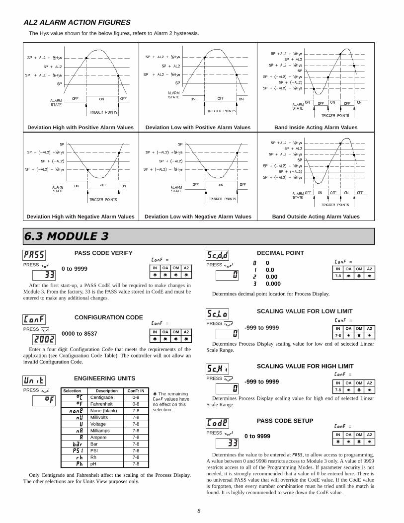
AL2 ALARM ACTION FIGURES
Deviation High with Positive Alarm V alues Deviation Low with Positive Alarm V alues Band Inside Acting Alarm V alues
Deviation High with Negative Alarm V alues Deviation Low with Negative Alarm V alues Band Outside Acting Alarm V alues
0 to 9999
PASS CODE VERIFY DECIMAL POINT
SCALING VALUE FOR LOW LIMIT
0000 to 8537-999 to 9999
CONFIGURATION CODE
ENGINEERING UNITS
After the first start-up, a PASS CodE will be required to make changes inModule 3. From the factory, 33 is the PASS value stored in CodE and must beentered to make any additional changes.
PASS
33
PRESS
Sc.d.d
0
PRESS
Sc.Lo
0
PRESSConF
2002
PRESS
Unit
°F
PRESS
ConF =
ConF =
ConF =
ConF =
ConF =
WWWW
A2OMOAIN
6.3 MODULE 3
WWWW
A2OMOAIN
Enter a four digit Configuration Code that meets the requirements of theapplication (see Configuration Code Table). The controller will not allow aninvalid Configuration Code.
Selection Description ConF: IN
°C Centigrade 0-8
°F Fahrenheit 0-8
none None (blank) 7-8
nU Millivolts 7-8
U Voltage 7-8
nA Milliamps 7-8
A Ampere 7-8
b8r Bar 7-8
PSI PSI 7-8
rh Rh 7-8
Ph pH 7-8
Only Centigrade and Fahrenheit affect the scaling of the Process Display.The other selections are for Units View purposes only.
Determines decimal point location for Process Display.
0 01 0.0
3
20.0000.00
WWW7-8
A2OMOAIN
Determines Process Display scaling value for low end of selected LinearScale Range.
SCALING VALUE FOR HIGH LIMIT
-999 to 9999
ConF =PASS CODE SETUP
0 to 9999
Sc.Hi
0
PRESS
Code
33
PRESS
Determines Process Display scaling value for high end of selected LinearScale Range.
WWW7-8
A2OMOAIN
WWWW
A2OMOAIN
The Hys value shown for the below figures, refers to Alarm 2 hysteresis.
WWW7-8
A2OMOAIN
W The remainingConF values haveno effect on thisselection.
Determines the value to be entered at PASS, to allow access to programming.A value between 0 and 9998 restricts access to Module 3 only. A value of 9999restricts access to all of the Programming Modes. If parameter security is notneeded, it is strongly recommended that a value of 0 be entered here. There isno universal PASS value that will override the CodE value. If the CodE valueis forgotten, then every number combination must be tried until the match isfound. It is highly recommended to write down the CodE value.
9
7.0 ON/OFF CONTROL EXPLANATION
8.0 PID CONTROL EXPLANATIONS
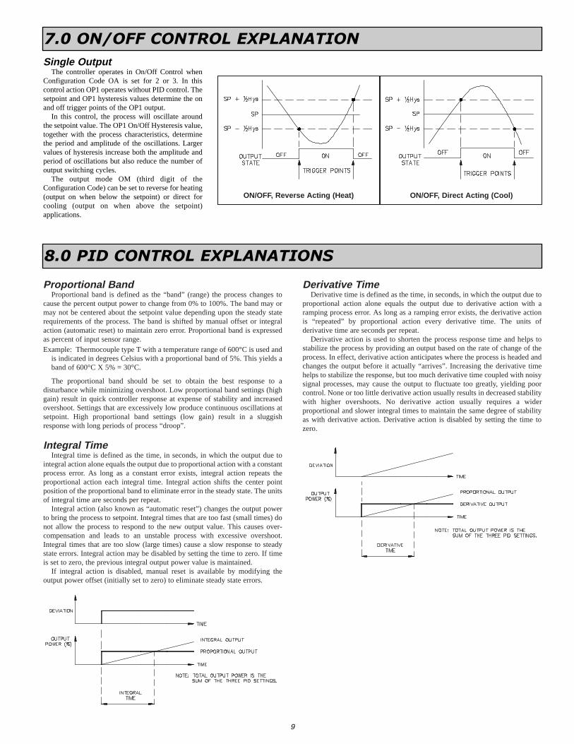
Single OutputThe controller operates in On/Off Control when
Configuration Code OA is set for 2 or 3. In thiscontrol action OP1 operates without PID control. Thesetpoint and OP1 hysteresis values determine the onand off trigger points of the OP1 output.
In this control, the process will oscillate aroundthe setpoint value. The OP1 On/Off Hysteresis value,together with the process characteristics, determinethe period and amplitude of the oscillations. Largervalues of hysteresis increase both the amplitude andperiod of oscillations but also reduce the number ofoutput switching cycles.
The output mode OM (third digit of theConfiguration Code) can be set to reverse for heating(output on when below the setpoint) or direct forcooling (output on when above the setpoint)applications.
ON/OFF, Direct Acting (Cool)ON/OFF, Reverse Acting (Heat)
Proportional BandProportional band is defined as the “band” (range) the process changes to
cause the percent output power to change from 0% to 100%. The band may ormay not be centered about the setpoint value depending upon the steady staterequirements of the process. The band is shifted by manual offset or integralaction (automatic reset) to maintain zero error. Proportional band is expressedas percent of input sensor range.Example: Thermocouple type T with a temperature range of 600°C is used and
is indicated in degrees Celsius with a proportional band of 5%. This yields aband of 600°C X 5% = 30°C.
The proportional band should be set to obtain the best response to adisturbance while minimizing overshoot. Low proportional band settings (highgain) result in quick controller response at expense of stability and increasedovershoot. Settings that are excessively low produce continuous oscillations atsetpoint. High proportional band settings (low gain) result in a sluggishresponse with long periods of process “droop”.
Integral T imeIntegral time is defined as the time, in seconds, in which the output due to
integral action alone equals the output due to proportional action with a constantprocess error. As long as a constant error exists, integral action repeats theproportional action each integral time. Integral action shifts the center pointposition of the proportional band to eliminate error in the steady state. The unitsof integral time are seconds per repeat.
Integral action (also known as “automatic reset”) changes the output powerto bring the process to setpoint. Integral times that are too fast (small times) donot allow the process to respond to the new output value. This causes over-compensation and leads to an unstable process with excessive overshoot.Integral times that are too slow (large times) cause a slow response to steadystate errors. Integral action may be disabled by setting the time to zero. If timeis set to zero, the previous integral output power value is maintained.
If integral action is disabled, manual reset is available by modifying theoutput power offset (initially set to zero) to eliminate steady state errors.
Derivative T imeDerivative time is defined as the time, in seconds, in which the output due to
proportional action alone equals the output due to derivative action with aramping process error. As long as a ramping error exists, the derivative actionis “repeated” by proportional action every derivative time. The units ofderivative time are seconds per repeat.
Derivative action is used to shorten the process response time and helps tostabilize the process by providing an output based on the rate of change of theprocess. In effect, derivative action anticipates where the process is headed andchanges the output before it actually “arrives”. Increasing the derivative timehelps to stabilize the response, but too much derivative time coupled with noisysignal processes, may cause the output to fluctuate too greatly, yielding poorcontrol. None or too little derivative action usually results in decreased stabilitywith higher overshoots. No derivative action usually requires a widerproportional and slower integral times to maintain the same degree of stabilityas with derivative action. Derivative action is disabled by setting the time tozero.

10
Auto-Tune is a user initiated function during which the controllerautomatically determines the PID settings based upon the processcharacteristics. During Auto-Tune, the controller oscillates the output andmonitors the input response. The AT indicator will be on during the Auto-Tuneoperation. At the end of this operation, the calculated PID values are stored inmemory and the controller returns to the Operation Mode.
Prior to initiating Auto-Tune, it is essential that the controller Cycle Timeparameter and the Setpoint value be configured for the application. Auto-Tuneis started or stopped using the tunE parameter in Module 2. The OvershootControl parameter in Module 1 should be set to 1.00 before initiating Auto-tune.
The controller automatically selects (based on the process conditions) one oftwo types of tuning algorithm. The length and number of cycles required tocalculate Proportional, Integral, and Derivative (PID) values are applicationdependent. (When Integral and Derivative parameters are configured for OFF,they are not included in the control algorithm.)
Step Response This type of tuning algorithm is automatically selected when the process
value is more than 5% span from the Setpoint at the start of Auto-Tune. Thismethod has the advantage of faster calculation, with a reasonable accuracy inthe results.
Natural FrequencyThis type of tuning algorithm is automatically selected when the process
value is close to the Setpoint. This method has the advantage of higher accuracyin the results, with a reasonable speed calculation.
Manual AdjustmentsTo aid in the adjustment of the PID parameters for improved process control,
a chart recorder is necessary to provide a visual means of analyzing the process.Compare the actual process response to the PID response figures with a stepchange to the process. Make changes to the PID parameters in no more than20% increments from the starting value and allow the process sufficient time tostabilize before evaluating the effects of the new parameter settings.
The Overshoot Control parameter can also be adjusted for tighter controlafter Auto-Tune.
9.0 AUTO-TUNE EXPLANATION
OVERSHOOT AND OSCILLA TIONS
To Dampen Response:- Increase Proportional Band- Increase Integral Time- Use Setpoint Ramping- Increase Derivative Time- Check Cycle Time
SLOW RESPONSE
To Quicken Response:- Decrease Proportional Band- Decrease Integral Time- Increase or Defeat Setpoint
Ramping- Decrease Derivative Time
TYPICAL RESPONSE CURVE

11
The controller has been fully calibrated at the factory. Display offset andscaling in Module 3 converts the input signal to a desired process value. If thecontroller appears to be indicating incorrectly or inaccurately, these parametersshould be checked first.
When recalibration is required (generally every 2 years), it should only beperformed by qualified technicians using appropriate, highly accurateequipment. The equipment must remain switched on for a minimum of one hourat a maintained environmental condition. Calibration may be aborted bydisconnecting power to the controller before pressing the “Return” key. Nocontroller parameter changes are necessary to perform calibration.
Input CalibrationFor thermocouple, mV and mA input calibration, connect a 50.000 mV input
to terminals 5 (-mV) and 6 (+mV). For RTD input calibration, place a 313.594ohm resister between terminals 6 and 12 and connect terminals 6 and 5 together.(If both types of input are being calibrated, then connect only one input, performthe complete calibration and repeat the procedure with the other input.)
Now perform the following:
10.0 CALIBRATION
TROUBLESHOOTING
PROBLEM REMEDIES
NO DISPLAY CHECK: Power level, power connections
CAN NOT ENTER MODULE 3 or PROGRAMMING MODE
CAN NOT REMEMBER PASS CODE ENTER: Other pass code combinations and press the “Return” key
CAN NOT CHANGE CONF CODE
INCORRECT DISPLAY VALUE CHECK: Configuration Code, Input Display Shift, Scaling Low, Scaling High
CHECK: Output wiring, output power, Configuration Code, setpoint or alarmthreshold value, hysteresis value
PRESS: The “Module” key until PASS appears then enter the correct pass codeand press the “Return” key
“- - - -” in DISPLA Y CHECK: Signal wiring, Configuration Code
“_ _ _ _” in DISPLA Y CHECK: Signal wiring, Configuration Code
“ConF” in DISPLA Y CHECK: Configuration Code
OUTPUT DOES NOT WORK
CONTROLLER OVERSHOOTS or DOES NOT GET TO SETPOINT
SOME PARAMETERS DO NOT APPEAR CHECK: Configuration Code
SETPOINT ENTRY STOPS AT A VALUE CHECK: Setpoint High Limit
CHECK: Overshoot Control, PID values, Setpoint SlopesPERFORM: Auto-tune
VERIFY: The controller is in Programming Module 3 Mode and code value is valid
For further technical assistance, contact technical support.
* Display may not vary more than ± 1 digit. If not stable after a few seconds, thenpress “Down” or “Up” and wait again. Continue this action until a stable display isshown.
Process Display“Return”
CAL.4“Return”
CAL.3“Return”
Wait for stable display *“Down” (If not calibrating for RTD, do not wait.)
CAL.2“Return”
Wait for stable display *“Down” (If calibrating for RTD, do not wait.)
CAL.1Enter programmed Pass Code, “Return”
PASS“Down” & “Up” together
reL“Return”, “Module”, “Module”, “Module”
DISPLAY RESULTPRESS KEY(S)
LIMITED WARRANTYThe Company warrants the products it manufactures against defects in materials and workmanship for a period limited to one year from thedate of shipment, provided the products have been stored, handled, installed, and used under proper conditions. The Company’s liability underthis limited warranty shall extend only to the repair or replacement of a defective product, at The Company’s option. The Company disclaimsall liability for any affirmation, promise or representation with respect to the products.
The customer agrees to hold Red Lion Controls harmless from, defend, and indemnify RLC against damages, claims, and expenses arising outof subsequent sales of RLC products or products containing components manufactured by RLC and based upon personal injuries, deaths,property damage, lost profits, and other matters which Buyer, its employees, or sub-contractors are or may be to any extent liable, includingwithout limitation penalties imposed by the Consumer Product Safety Act (P.L. 92-573) and liability imposed upon any person pursuant to theMagnuson-Moss Warranty Act (P.L. 93-637), as now in effect or as amended hereafter.
No warranties expressed or implied are created with respect to The Company’s products except those expressly contained herein. The Customeracknowledges the disclaimers and limitations contained herein and relies on no other warranties or affirmations.

12
PARAMETER VALUE CHAR T Programmer _____ ___________ Date ________T32 1/32 DIN PID Controller Meter# _____________ Pass Code ____ ______
Based on the Configuration Code of the controller, some parametersmay not be available.
Module 1
Module 2
Module 3
DISPLAY PARAMETER USER SETTING
SL. u SETPOINT SLOPE-UP
SL. d SETPOINT SLOPE-DOWN
S.P. L SETPOINT LOW LIMIT
S.P. H SETPOINT HIGH LIMIT
A1hY
A2hY
AL1 HYSTERESIS
AL2 HYSTERESIS
t.FiL FILTER TIME CONSTANT
In.Sh INPUT DISPLAY SHIFT
DISPLAY PARAMETER USER SETTING
ConF CONFIGURATION CODE
Unit ENGINEERING UNIT
Sc.d.d DECIMAL POINT
Sc.Lo SCALING LOW
Sc.Hi SCALING HIGH
Code PASS CODE SETUP
PROGRAMMING MODE CHART
AL1 THRESHOLDA1S.P
OP1 % POWER HIGH LIMITOP. H
OP1 OVERSHOOT CONTROLO.C.
OP1 CYCLE TIMEt.c.
OP DERIVATIVE TIMEt.d.
OP1 INTEGRAL TIMEt.i.
OP1 PROPORTIONAL BANDP.b.
OP1 HYSTERESIShY.
AL2 THRESHOLDA2S.P
USER SETTINGPARAMETERDISPLAY