Embed Size (px)
Citation preview
GE Push Buttons
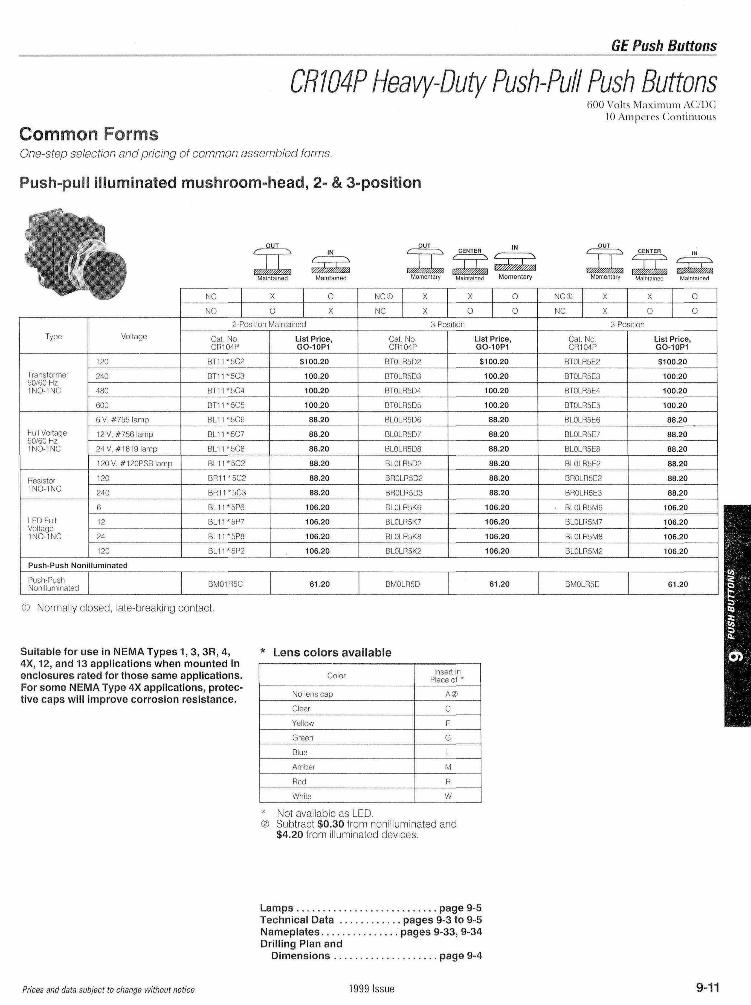
CRW4P Heavy-Duty Push-Pull Push Buttons600 Volts Maximum AC/DC
10 Ampeies Continuous
Common FormsOne-step selection and pricing of common assembled forms
Push-pull illuminated mushroom-head, 2- & 3-position
Momentary Maintained Momentary Momentary Maintained
Type
Transformer50/60 Hz1 NO INC
Full Voltage50/60 Hz1NO 1NC
Resistor1NO 1NC
LED FullVoltage1NO 1NC
Voltage
120
?40
480
600
6V #755 lamp
12V #756 lamp
24V # 1 8 1 9 lamp
120V #120PSBIamo
120
240
6
1 2
24
120
NC X 0
NO 0 X
2 Position Maintained
Cat NoCR104P
BT11*5C2
BT11*5C3
B T 1 1 * 5 C 4
BT11*5C5
BL11*5C6
BL11*5C7
BL11*5C8
BL11*5C2
B R 1 1 * 5 C 2
B R 1 1 * 5 C 3
BL11*5P6
BL11*5P7
BL11*5P8
B L 1 1 *5P2
List Price,GO-10P1
$100.20
100.20
100.20
100.20
88.20
88.20
8820
8820
88.20
88.20
106.20
106.20
10620
10620
NC© X
NC X
X 0
0 O
3 Position
Cat NoCR104P
BTOLR5D2
BTOLR5D3
BTOLR5D4
BTOLR5D5
BIOLR5D6
BLOLP5D7
BLOLR5D8
BLOLR5D2
BROLR5D2
BROLR5D3
BLOLR5K6
BLOLR5K7
BLOLR5K8
BLOLR5K2
List Price,GO-10P1
$10020
100.20
100.20
100.20
88.20
88.20
8820
88.20
88.20
88.20
106.20
106.20
10620
106.20
NC® X
NC X
X 0
0 0
3 Position
Cat NoCR104P
BTOLR5E2
BTOLR5E3
BTOLR5E4
BTOLR5E5
BLOLR5E6
BLOLR5E7
BLOLR5E8
BLOLR5E2
BROLR5E2
BROLR5E3
BLOLR5M6
BLOLR5M7
BLOLR5M8
BLOLR5M2
List Price,GO-10P1
$100.20
100.20
100.20
100.20
88.20
88.20
88.20
88.20
88.20
88.20
106.20
106.20
106.20
106.20
Push-Push Non llummated
Push PushNonillummated BM01R5C 61.20 BMOLR5D 61.20 BMOLR5E 61 20
© Normally closed late-breaking contact
Suitable for use in NEMA Types 1, 3, 3R, 4,4X, 12, and 13 applications when mounted inenclosures rated for those same applications.For some NEMA Type 4X applications, protec-tive caps will improve corrosion resistance.
* Lens colors available
Coior
No lens cap
Clear
Yellow
Green
Blue
Amber
Red
White
Insert inPlace of *
A©
C
E
G
L
M
R
W
Not available as LEDSubtract $0.30 from nonilluminated and$4.20 from illuminated devices
L a m p s . . . . . . . . . . . . . . . . . . . . . . . . . . . page 9-5Technical Data . . . . . . . . . . . . pages 9-3 to 9-5Namepla tes . . . . . . . . . . . . . . . pages 9-33, 9-34Drilling Plan and
Dimensions . . . . . . . . . . . . . . . . . . . . page 9-4
Prices and data subject to change without notice 1999 Issue 9-11
GE Push Buttons
Section 9
The GE push button offering includes a complete line of controlunits and stations in both full size push buttons (30 mm) and inminiature size devices (22 mm) which are designed to be used innumerous types of industrial applicationsThe CR104P full size heavy-duty oiltight and watertight line iscomplete with a variety of accessories and enclosuresLight Tower Status Indicating Lights provide information at aglance in industrial or commercial environments where you needto transmit and receive information across a distance Modularityand versatility make them valuable in a broad range of applicationsGE s C-2000™ 22mm Global Push Buttons are designed to beapplied in just about any application worldwide C-2000 pushbuttons conform to all major world standards and are UL listedand CSA Certified All devices except the double push button arerated for NEMA1 3 3R 3S 4 4X 12 13 and IP66 when mountedin a suitable enclosure C 2000 push buttons are manufactured inan ISO 9000 facility assuring you that these products comply withquality standards that are recognized worldwide Pre engravednameplates are available in French Spanish Italian German andEnglish The C-2000 push button line is globally available underthe same catalog numbers packaging and markings anywhere inthe worldAn entire listing of CR2943 and CR2941 standard duty pushbutton control stations is available suitable for NEMA Type 1 44X and 7 and 9 applications
Heavy Duty 30mm Push ButtonsSelector Switches Indicating Lights Accessories
(CR104P Series) 9 2 to 9 36
Light Tower Status Indicating Lights(SL Series) 9 37 to 9 47
C-2000™ 22mm Global Push Buttons(P9 Series) 9 48 to 9-100
Standard Duty Push Button Control Stations(CR2943 and CR2941 Series) 9 101 to 9 103
Palm Switches 9 104
References:See Publication Index Section 18
Data subject to change without notice 1999 Issue 9-1
GE Push Buttons
CR104P Heavy-Duty Push ButtonsTechnical DataGeneral Specifications
Contacts
Standards & approvals
Enclosure ratings
Finger protection atterminals
Temperature range
Climate suitability/humidity
Shock and vibration
Operating force
Wire size
Torque requirements
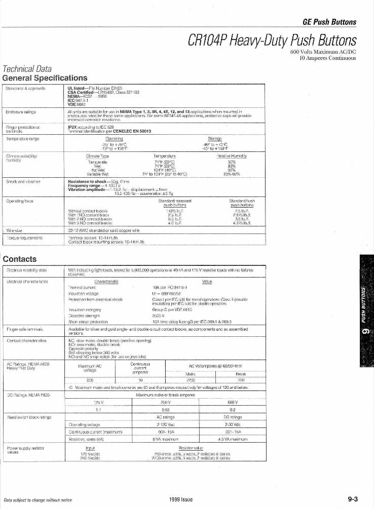
UL listed— File Number E2403CSA Certified— LR15492, Class 321103NEMA— ICS2— 1988IEC 947 5 1VDE 0660
All units are suitable for use in NEMA Type 1 ,enclosures rated for those same apphcationsimproved corrosion resistance
3, 3R, 4, 4X, 1 2, and 1 3 applications when mounted inFor some NEMA 4X applications protective caps will provide
IP2X according to IEC 529Terminal identification per CENELEC EN 50013
Operating-25° to +70°C-13° to+158°F
Climate TypeTemperate
WetHot Wet
Variable Wet 74
Storage40°to+70°C
-40°to+158°F
Temperature74°F (23°C)74°F (23°C)104°F(40°C)
°to104°F(23°to40°C)
Relative Humidity50%83%92%
83% 92%
Resistance to shock — 50g 1 1 m sFrequency range— 1 100 HzVibration amplitude — 1-1 3 2 Hz — d splacement ± 1 mm
13 2-100 Hz— acceleration ±0 7g
Without contact blocksWith 1 NO contact blockWith 2 NO contact blocksWith 3 NO contact blocks
Standard recessedpush buttons
1 625 Ib /f2 5 Ib /f3 5 Ib /f40lb/ f
Standard flushpush buttons
2 5 Ib /f2 875 Ib /f
3 5 Ib /f4 375 Ib /f
22- 1 2 AWG stranded or solid copper wire
Terminal screws 1 0 - 1 4 in /IbContact block mounting screws 1 0 - 1 4 in/lb
Electrical reliability data
Electrical characteristics
Finger-sate terminals
Contact characteristics
AC Ratings NEMAA600Heavy Pilot Duty
DC Ratings NEMA P600
Reed switch block ratings
Power supply resistorvalues
With indicating light loads tested tor 5,000,000 operations at 40mA and 1 1 5 V resistive loads with no failuresobserved
CharacteristicThermal currentInsulation voltageProtection from electrical shock
Insulation categoryDielectric strengthShort-circuit protection
Value1 0A per IEC 947-5-1Ui = 660Vac/dcClass I per IEC 536 for metal operators Class II (doubleinsulation) per IEC 536 for plastic operatorsGroup C per VDE 01 102500V1 0A time-delay fuse gG per IEC ?69 1 & 269 3
Available for silver and gold single- and double-circuit contact blocks, as components and as assembledversions
NC slow make, double break (positive opening}NO slow make double breakOpposite polaritySelf-cleaning below 300 voltsNO and NC snap action (for use on joysticks)
Maximum ACvoltage
600
Cocnu'™°t
us AC Voltamperes @ 60/50 Hz ®amperes Make
10 7200Break720
® Maximum make and break currents are 60 and 6 amperes respectively for voltages of 1 20 and below
125V
1 1
Operating voltage
Continuous current (maximum)
Resistive, watts (VA)
Input120Vac/dc240Vac/dc
Maximum make or break amperes
250V
055
AC ratings
2 120 Vac
0 0 1 - 1 5 A
8 VA maximum
Resistor value
600V
02
DC ratings
2-30 Vdc
001 15A
4 5 VA maximum
750 ohms ±5%, 5 watts, 2 resistors in series2700 ohms ±5%, 5 watts, 2 resistors in series
600 Volts Maximum AC/DC10 Amperes Continuous
Data subject to change without notice 1999 Issue 9-3
1
GE Push Buttons
CH104P Heavy-Duty Push Buttons600 Volts Maximum AC/DC10 Ampei es Continuous
Technical Data, Dimensions
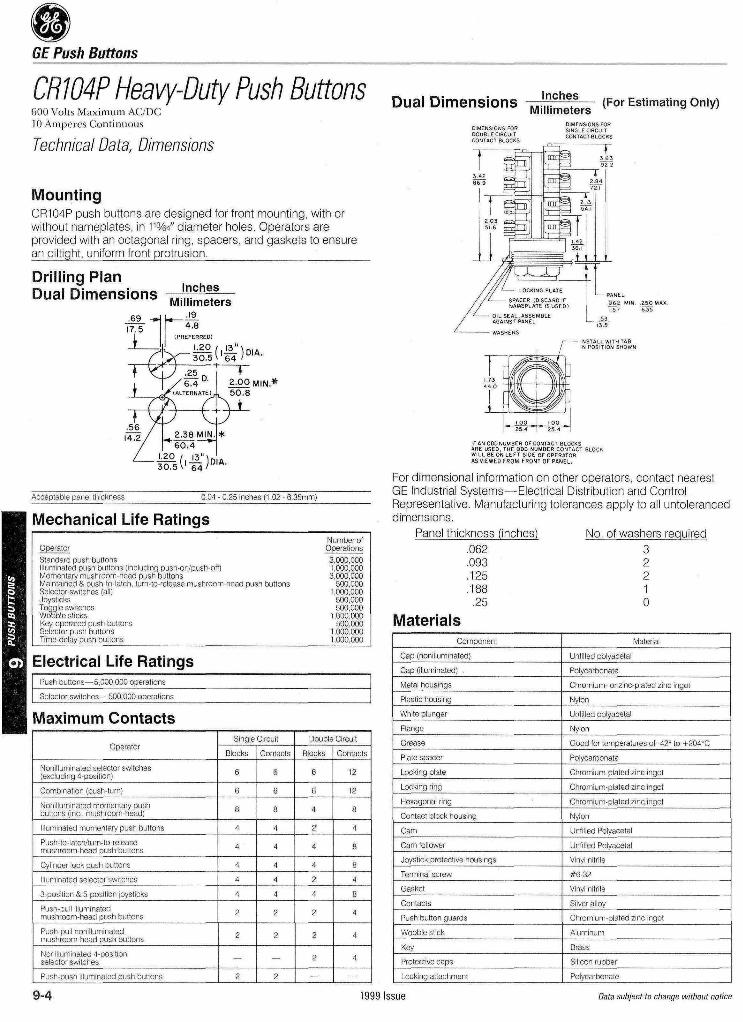
MountingCR104P push buttons are designed for front mounting, with orwithout nameplates, in 11%4" diameter holes Operators areprovided with an octagonal ring, spacers, and gaskets to ensurean oiltight, uniform front protrusion________________
Drilling PlanDual Dimensions lnches
Millimeters_J9_
"" 4.8(PREFERRED)
-gS ('&>*•
Acceptable panel thickness 0 04 0 25 inches (1 02 6 35mm)
Mechanical Life RatingsNumber ofOperations3 000 0001 000 0003 000 000500 000
1 000 000500 000500 000
1 000 000500 000
1 000 0001 000 000
Electrical Life RatingsPush buttons—5 000 000 operations
Selector switches—500 000 operations
Maximum ContactsOperator
Nonilluminated selector switches(excluding 4 position)
Combination (push turn)
Nonilluminated momentary pushbuttons (incl mushroom-head)
Illuminated momentary push buttons
Push to latch/turn to releasemushroom head push buttons
Cylinder lock push buttons
Illuminated selector switches
3 position & 5 position joysticks
Push pull illuminatedmushroom head push buttons
Push pull nonilluminatedmushroom head push buttons
Nonilluminated 4 positionselector switches
Push push illuminated push buttons
Single Circuit
Blocks
6
6
8
4
4
4
4
4
2
2
-
2
Contacts
6
6
8
4
4
4
4
4
2
2
-
2
Double Circuit
Blocks
6
6
4
2
4
4
2
4
2
2
2
-
Contacts
12
12
8
4
8
8
4
8
4
4
4
-
Dual Dimensions InchesMillimeters- (For Estimating Only)
DIMENSIONS FORDOUBLE CIRCUITCONTACT BLOCKS
DIMENSONS FORSINGLE CIRCUITCQNTACTBLOCKS
"sir [rr HB Im:§ Ip^=^±=q i_«I \ ^ i !
/// LOCKING PLAT£ - PANEL
// %SSgi$?%5$& fff «'« |f§MA*/ <-—— OIL SEAL ASSEMBLE *,
/ AGAINST PANEL '— -~r-
•^——————— WASHERS
,——— INSTALL WITH TAB/ IN POSITION SHOWN
__I0l> I 00__—IT? 5sTn
IF AN ODD NUMBER OF CONTACT BLOCKSARE USED, THE ODD NUMBER CONTACT SLOCKWILL BE ON LEFT SIDE OF OPERATORAS VIEWED FROM FRONT OF PANEL
For dimensional information on other operators, contact nearestGE Industrial Systems—Electrical Distribution and ControlRepresentative Manufacturing tolerances apply to all untoleranceddimensions
Panel thickness (inches) No of washers required062 3093 2125 2188 125 0
MaterialsComponent
Cap (nonillum.nated)
Cap (illuminated)
Metal housings
Plastic housing
White plunger
Flange
Grease
Plate spacer
Locking plate
Locking ring
Hexagonal ring
Contact block housing
Cam
Cam follower
Joystick protective housings
Terminal screw
Gasket
Contacts
Push button guards
Wobble stick
Key
Protective caps
Locking attachment
Material
Unfilled polyacetal
Polycarbonate
Chromium or zinc plated zinc ingot
Nylon
Unfilled polyacetal
Nylon
Good for temperatures of 42° to +-204°C
Polycarbonate
Chromium plated zinc ingot
Chromium plated zinc ingot
Chromium plated zinc ingot
Nylon
Unfilled Polyacetal
Unfilled Polyacetal
Vinyl nitnle
#632
Vinyl nitnle
Silver alloy
Chromium plated zinc ingot
Aluminum
Brass
Silicon rubber
Polycarbonate
9-4 1999 Issue Data subject to change without notice
,69 -Hh————TFlf 4-8
f (PREFERRED)
""T^sJraj'g)™-I 1/6^4 D g.OOMIN*
_ !______ -XtALTERNATE! 1 50.8
•56 / l"^I4~? / 2.38 MIN.|*
/ """604^1
^-*5T5('£K
OperatorStandard push buttonsIlluminated push buttons (including push on/push off)Momentary mushroom head push buttonsMaintained & push to latch turn to release mushroom head push buttonsSelector switches (all)JoysticksToggle switchesWobble sticksKey operated push buttonsSelector push buttonsTime delay push buttons__________________________
B*>
GE Push Buttons
CR104P Heavy-Duty Push Buttons
Lamp SelectionIncandescent, neon, and light emitting diode (LED) lamps areavailable for use in indicating lights, illuminated push buttons, andilluminated selector switches Incandescent lamps have traditionallybeen the most frequently used, but it is wise to review the char-acteristics of the different types of lamps and select the one that ismost appropriate for the application Although the incandescentlamp offers the lowest initial cost, the LED is usually the mosteconomical over the long term, due to its long life, resistance toshock and vibration, and lower power consumption Benefits ofLEDs include• Resistance to Shock and Vibration—Since LEDs are solid
state, they are completely impervious to the problems associatedwith shock and vibration that can significantly reduce the life ofincandescent lamps by mechanically breaking the filament Thehigh inrush currents at startup associated with incandescentsalso act to significantly reduce the life of lamps used in frequenton-off applications
• Longer Life—The LEDs used with CR104P push buttons havea service life of 100,000 hours (11 years) compared to 20,000 hours(28 months) for the neon lamps, and 2,000 hours (3 months) forthe standard incandescent lamps
• Reduced Power Consumption—The LEDs used for the
600 Volts Maximum AC/DC10 Ampcies Continuous
CR104P push buttons consume between 10% and 52% lesspower than the equivalent incandescent lamp The table belowshows the power consumption of each type
• Lower Operating Temperature—Because of the lower powerconsumption and greater efficiency of LEDs, they operate muchcooler than incandescent lamps Thus, in applications whereheat in the enclosure could be a problem, LED lamps are abetter choice
Incandescent bulbs are recommended for light-duty applicationsand panels not subject to shock and vibration Neon lamps offer amiddle ground, at a cost and performance between the LED andthe incandescent, but can have problems associated with flickerinduced by noise and frequency LED lamps offer the best overallperformance for the long termLamp Comparison
Bulb Type
LED
Incandescent
Neon
Lifespan(Hours)
100,000
2000
20000
Shock &Vibrationimmunity
High
Low
Medium
OperatingTemperature
Medium
High
Low
PowerConsumption
Medium
High
Low
Brightness
Medium
High
Low
Type
Full Voltage/Transformer
Resistor
Cluster Lights
Volts AC/DC
6 (20 000 hours)
12 (15 000 hours)
24 (2 500 hours)
120 (telephone slide)
130 (miniature bayonet)
240
120
1 2
24
6
IncandescentCR104P
XA16
XA12
XA14
XA52
XA54
XA52
XA15
XA22
XA24
XA26
Watts
95
1 12
1 12
3
26
3
3
96
1 12
1 2
LEDCR104P
XA36*
XA32*
XA34*
—
XA38*
—
—
—
—
-
Watts
054
072
072
—
1 2
—
—
—
—
-
NeonCR104P
—
—
—
—
XA19
—
—
—
—
-
Watts
——
—
—
0077
—
—
—
—
-
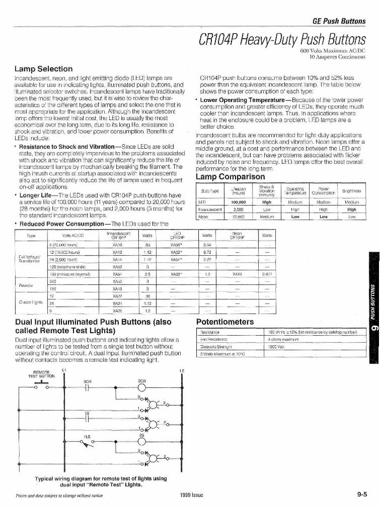
Dual Input Illuminated Push Buttons (alsocalled Remote Test Lights)Dual input illuminated push buttons and indicating lights allow anumber of lights to be tested from a single test button withoutoperating the control circuit A dual input illuminated push buttonwithout contacts becomes a remote test indicating light
PotentiometersResistance
End Resistance
Dielectric Strength
2 Watts Maximum at 70°C
100 ohms ±10% (list resistance by catalog number)
4 ohms maximum
1 000 Vac
REMOTETEST BUTTON
2CRois
Typical wiring diagram for remote test of lights usingdual input "Remote Test" Lights.
Prices and data subject to change without notice 1999 Issue 9-5