Embed Size (px)
Citation preview

2002 Southwest Test Workshop Brett Grossman
June 9,2002ITTO Electrical Modeling 1
Modeling Distributed Power Delivery Effects Modeling Distributed Power Delivery Effects Modeling Distributed Power Delivery Effects in High Performance Sort Interface Unitsin High Performance Sort Interface Unitsin High Performance Sort Interface Units
Tim SwettlenBrett Grossman
ITTO Electrical ModelingIntel Corporation

2002 Southwest Test Workshop Brett Grossman
June 9,2002ITTO Electrical Modeling 2
Power Modeling: A look backPower Modeling: A look backPower Modeling: A look back
time
Spice Based:(lumped time domain)Menu based:
Decoupling:•Standard (1.0uF, 0.1uF, 0.01uF):•Other (custom):
1990 Today
Spreadsheet based:(lumped freq. Domain)
ADS Based:(lumped time/freq domain)
2002 Southwest Test Workshop Brett Grossman
June 9,2002ITTO Electrical Modeling 3
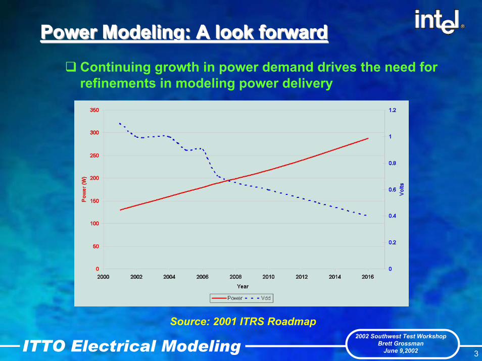
Power Modeling: A look forwardPower Modeling: A look forwardPower Modeling: A look forwardContinuing growth in power demand drives the need for refinements in modeling power delivery
Source: 2001 ITRS Roadmap

2002 Southwest Test Workshop Brett Grossman
June 9,2002ITTO Electrical Modeling 4
What is 100A?What is 100A?What is 100A?
Different viewpoints of 100 Amps
• What might it look like if ½ the DUT were idle?
2002 Southwest Test Workshop Brett Grossman
June 9,2002ITTO Electrical Modeling 5
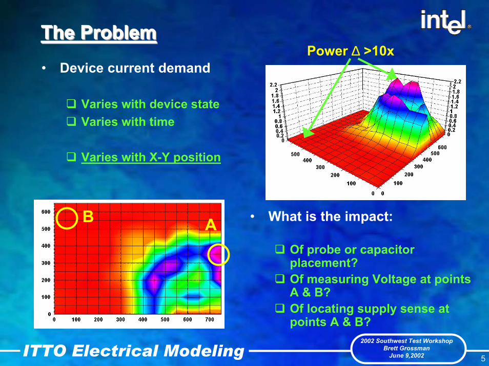
The Problem The Problem The Problem Power ∆ >10x
• Device current demand
Varies with device stateVaries with time
Varies with X-Y position
AB • What is the impact:
Of probe or capacitor placement?Of measuring Voltage at points A & B?Of locating supply sense at points A & B?

2002 Southwest Test Workshop Brett Grossman
June 9,2002ITTO Electrical Modeling 6
The ImpactThe ImpactThe Impact• Example :
Measured droop voltages at two die locations (A&B)
(> 100 mV delta!)Device running 80% max speed executing reset sequence. Voltages measured at the DUT/probe interface.

2002 Southwest Test Workshop Brett Grossman
June 9,2002ITTO Electrical Modeling 7
Power Delivery System (PDS)Power Delivery System (PDS)Power Delivery System (PDS)Simplified Block Diagram
DUT
Probes
SpaceTransformer
PDS• Uniform design
Probes, decoupling, etc.• Modeling only represents
lumped componentsNo (X,Y) understanding
DUT• Non uniform demand• Non uniform decoupling• Non-uniform parasitics
Vdroop• Performance metric for PDS• Measure of voltage change to an applied current
x
ATE Supply
PCB
z
y

2002 Southwest Test Workshop Brett Grossman
June 9,2002ITTO Electrical Modeling 8
Understanding a solution Understanding a solution Understanding a solution ––– DUT levelDUT levelDUT level
• DUT non-uniform elementsI sourceRLC elementsAll data from DUT simulations
• Approach to issue:Discretize die area
Mesh size is a function of transient frequency
Model components with spatial variance
Power demanddevice decouplingmetal grid parasitics
XY power map
Discretized power map

2002 Southwest Test Workshop Brett Grossman
June 9,2002ITTO Electrical Modeling 9
Die cell modelDie cell modelDie cell model
• Typical modelControlled Current Source‘constant’ current rampRLC parasitics
metal grid parasiticsdecoupling
diecell
diecell
diecell
diecell
diecell
diecell
diecell
diecell
diecell
diecell
diecell
diecell
diecell
diecell
diecell
diecell
diecell
diecell
diecell
diecell
diecell
diecell
diecell
diecell
diecell
m x n array of die cells

2002 Southwest Test Workshop Brett Grossman
June 9,2002ITTO Electrical Modeling 10
Die cell modelDie cell modelDie cell model
• Alternate modelControlled current source
Control voltage into port 1DUT voltage into port 2
RLC parasiticsstill included though not illustrated here
Current ramp (port 3) is now a function of the instantaneous voltage across the cell

2002 Southwest Test Workshop Brett Grossman
June 9,2002ITTO Electrical Modeling 11
Die cell modelDie cell modelDie cell model
• Typical vs. Alternate model response
‘constant’ current ramp
Vdroop ∆
current ramp as a function of cell voltage

2002 Southwest Test Workshop Brett Grossman
June 9,2002ITTO Electrical Modeling 12
Understanding a solution Understanding a solution Understanding a solution ––– Probe levelProbe levelProbe level
• Probe cell definitionMeshed similar to the DUTCell modeled as probe pair w/ coupling
• Considerations:Take advantage of fewer probes in low power areaAllow for increased probes in areas of high demand
XY power map
Discretized power map

2002 Southwest Test Workshop Brett Grossman
June 9,2002ITTO Electrical Modeling 13
Probe cell modelProbe cell modelProbe cell model
• Probe modelsProbe styles fully characterized
Agilent 8753 VNA0.050 - 5.05 GHzCustom fixturing
m x n array of probe cells
probecell
probecell
probecell
probecell
probecell
probecell
probecell
probecell
probecell
probecell
probecell
probecell
probecell
probecell
probecell
probecell
probecell
probecell
probecell
probecell
probecell
probecell
probecell
probecell
probecell

2002 Southwest Test Workshop Brett Grossman
June 9,2002ITTO Electrical Modeling 14
Probe cell modelProbe cell modelProbe cell model
• Probe uniformityCurrently do not probe every bump
1 of 3, 1 of 5, 1 of 7…Currently maintain a uniform probe array
Limits our ability to meet Vdroop targetsIncreased resolution required
Vcc probe distribution Vss probe distribution
2002 Southwest Test Workshop Brett Grossman
June 9,2002ITTO Electrical Modeling 15
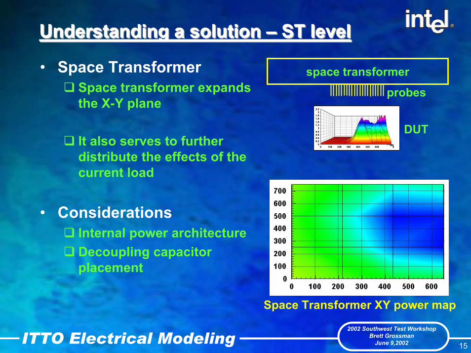
Understanding a solution Understanding a solution Understanding a solution ––– ST levelST levelST level
• Space TransformerSpace transformer expands the X-Y plane
It also serves to further distribute the effects of the current load
• ConsiderationsInternal power architecture Decoupling capacitor placement
space transformer
DUT
probes
Space Transformer XY power map

2002 Southwest Test Workshop Brett Grossman
June 9,2002ITTO Electrical Modeling 16
Space Transformer cell modelSpace Transformer cell modelSpace Transformer cell model
• ST MeshMesh area is no longer confined to the die areaContinuing the same mesh as the die would produce a huge array
• Mesh sizeAgain determined as a function of transient frequencyModel reduction
Discretized power map
2002 Southwest Test Workshop Brett Grossman
June 9,2002ITTO Electrical Modeling 17
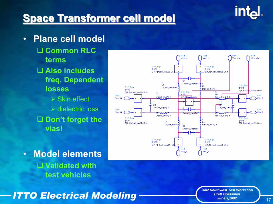
Space Transformer cell modelSpace Transformer cell modelSpace Transformer cell model
• Plane cell modelCommon RLC termsAlso includes freq. Dependent losses
Skin effectdielectric loss
Don’t forget the vias!
• Model elements Validated with test vehicles
2002 Southwest Test Workshop Brett Grossman
June 9,2002ITTO Electrical Modeling 18
Understanding a solution Understanding a solution Understanding a solution ––– otherotherother
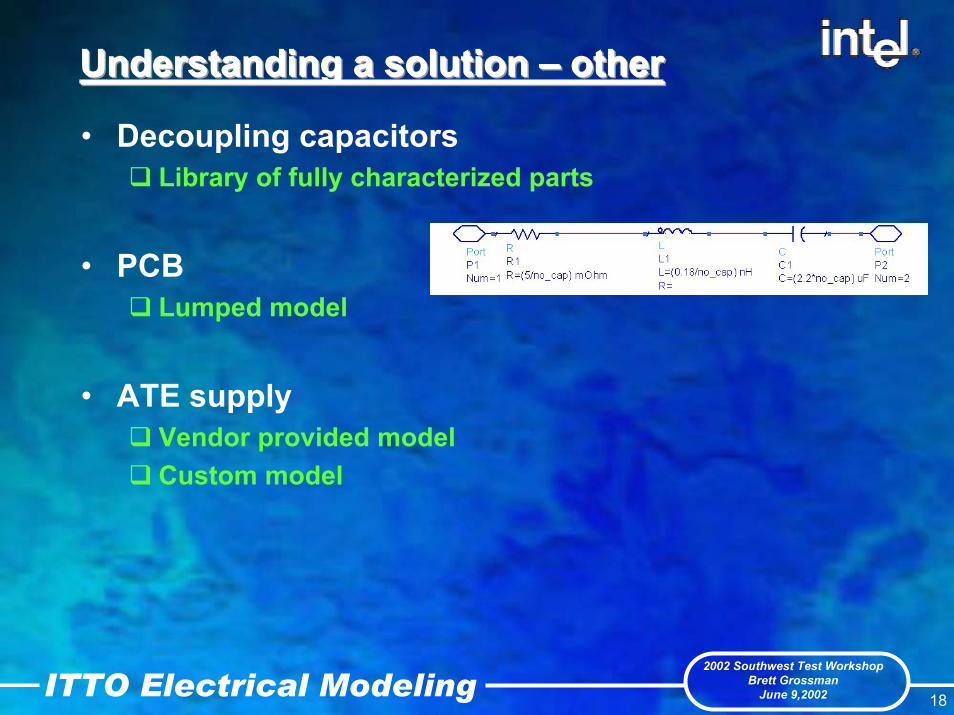
• Decoupling capacitorsLibrary of fully characterized parts
• PCB Lumped model
• ATE supplyVendor provided modelCustom model

2002 Southwest Test Workshop Brett Grossman
June 9,2002ITTO Electrical Modeling 19
Bringing the model togetherBringing the model togetherBringing the model together
• Model assemblyHierarchical Large number of components in fully assembled model

2002 Southwest Test Workshop Brett Grossman
June 9,2002ITTO Electrical Modeling 20
Distributed droop simulationsDistributed droop simulationsDistributed droop simulations
• Simulated Vdroop responseResponse at m x n pointsacross the array

2002 Southwest Test Workshop Brett Grossman
June 9,2002ITTO Electrical Modeling 21
Next StepsNext StepsNext Steps
• Improved model management• Continued refinement• Extending the model to multi-die applications
J3 J4
J5 J6J9 J10
J11 J12
2002 Southwest Test Workshop Brett Grossman
June 9,2002ITTO Electrical Modeling 22
SummarySummarySummary
• Shrinking margins continue to drive refinements in power modeling accuracy
• Non-uniform power demand will further exacerbate this concern
• Question model assumptions, create measurement based models
• Distribute model elements in three dimensions

2002 Southwest Test Workshop Brett Grossman
June 9,2002ITTO Electrical Modeling 23
AcknowledgementAcknowledgementAcknowledgement
• We would like to recognize our colleagues Kevin Zhu and Sayed Mobin for their contributions to this project

2002 Southwest Test Workshop Brett Grossman
June 9,2002ITTO Electrical Modeling 24
ReferencesReferencesReferences
K. Lee and A. Barber, “Modeling and Analysis of Multichip Module Power Supply Planes”, IEEE Trans. on Components Packaging and Manufacturing Technology, Part B, Vol. 18, No. 4, Nov. 1995, pp. 628-639Henry Wu, Jeffery Meyer, Ken Lee, Alan Barber, “Accurate Power Supply and Ground plane pair models”, Proceedings of the 1998 Topical Meeting on Electrical Performance of Electronic Packaging, Oct. 1998, pp. 163-166M.A. Schmitt, K. Lam, L.E. Mosely, G. Choksi, and K. Bhattacharyya, “Current Distribution on Power and Ground Planes of a Multilayer Pin Grid Package”, Proceedings International Electronics Packaging Society, 1988, pp. 467-475Larry Smith, Tanmoy Roy, Raymond Anderson, “Power Plane Spice Models for Frequency and Time Domain”, Proceedings of the 9th
Topical Meeting on Electrical Performance of Electronic Packaging, Oct. 2000, pp. 51-54