Embed Size (px)
Citation preview

Modeling and Validation of Business Process Families
Gerd Gronera, Marko Boskovicb, Fernando Silva Parreirasc, Dragan Gasevicd
aWeST Institute, University of Koblenz-Landau, GermanybResearch Studios Austria, Austria
cFUMEC University, BrazildAthabasca University, Canada
Abstract
Process modeling is an expensive task that needs to encompass requirements of different stakeholders, assure compliancewith different standards, and enable the flexible adaptivity to newly emerging requirements in today’s dynamic globalmarket. Identifying reusability of process models is a promising direction towards reducing the costs of process modeling.Recent research has offered several solutions. Such solutions promote effective and formally sound methods for variabilitymodeling and configuration management. However, ensuring behavioral validity of reused process models with respect tothe original process models (often referred to as reference process models) is still an open research challenge. To addressthis challenge, in this paper, we propose the notion of business process families by building upon the well-known softwareengineering discipline – software product line engineering. Business process families comprise (i) a variability modelingperspective, (ii) a process model template (or reference model), and (iii) mappings between (i) and (ii). For businessprocess families, we propose a correct validation algorithm ensuring that each member of a business process familyadheres to the core intended behavior that is specified in the process model template. The proposed validation approachis based on the use of Description Logics, variability is represented by using the well-known Feature Models and behaviorof process models is considered in terms of control flow patterns. The paper also reports on the experience gained in twoexternal trial cases and results obtained by measuring the tractability of the implementation of the proposed validationapproach.
Keywords: business process families, control flow relations, validation, process model variability, process modelconfiguration
1. Introduction
Process modeling is an expensive task [1], and the moredetailed and fine-grained a process is the more effort is re-quired to build the corresponding process model. This canbe attributed to several (crosscutting) reasons. First, noorganization is an isolated island in today’s global econ-omy. Rather, processes in individual organizations are typ-ically based on collaboration with several other (partner)organizations. Therefore, any parts of processes prone tooften changes in such a collaborative environment shouldcarefully be considered and reflected in the models. Next,the process modeling task typically requires the involve-ment of stakeholders with different backgrounds (e.g., ac-counting, sales, security, information technology, or soft-ware development) who need to bring together critical(and sometimes conflicting) perspectives to processes be-ing modeled. Finally, process models need to be adaptivein order to be able to serve to stakeholders who might nothave the exact same, yet, rather similar requirements.
Email addresses: [email protected] (Gerd Groner),[email protected] (Marko Boskovic),[email protected] (Fernando Silva Parreiras),[email protected] (Dragan Gasevic)
Recently, process modeling research and practice havebeen looking for novel methods and techniques that canhelp to tackle the complexity of the process modeling task.Obviously, process reusability [2] is one of the most desir-able attributes, which process models need to have. Reus-ability of processes can reduce the costs of the involvementof different stakeholders all over in different situations.Reusability of process models can also scale up the devel-opment of software that enact the processes. Reusabilitycan also increase the quality of processes by reducing theprobability of potential defects, assure compliance to cer-tain standards the processes need to adhere to, and easechange propagation.
Capturing and systematically managing variability inprocess models is one of the main prerequisites for theireffective and scalable reusability [3]. By variability captur-ing we primarily refer to the representation of individualvariation points allowing stakeholders to make their indi-vidual choices when reusing a process model. However,such variation points are typically not completely inde-pendent from the rest of a process model being reused.Often, choices made about some variability points have di-rect implications on other variation points (e.g., deciding
Preprint submitted to Information Systems September 7, 2012
to include a credit card payment option in a process hasa direct implication about what additional activities mustbe included in order to assure security of such payments).This directly indicates that for an effective variability cap-turing and management in business processes, there is aneed to have not only a representation of variability points,but also algorithms that can guide the stakeholders whenmaking their choices [4].
Commonly, existing work considers the task of processmodel reusability in terms of configurable reference mod-els [4, 5, 6], where a reference process model contains vari-ation points. These variation points offer choices like theselection of a particular branch [4] and the hiding or block-ing of certain activities [5, 6]. Instead of building severalrelated business process models from scratch, the referenceprocess models are narrowed down towards an individu-alized business process model. In order to perform theconfiguration of process models, such approaches requirefrom stakeholders knowledge of process modeling and howelements of a process model depend on each other. Tomake the configuration process more understandable, thequestionnaire-based approach [7] guides the stakeholdersby asking questions of relevance to the particular choicesthey need to make. However, this approach does not of-fer an automated solution, which can ensure that for eachpossible set of valid choices, the stakeholders can make,there is a business process consistent with the behaviorspecified in the original reference business process. Thischallenge is exactly tackled in this paper.
We propose the notion of Business Process Families, bybuilding upon the principles of the well-established soft-ware engineering discipline – software product line engi-neering (SPLE) [8]. Having the variability management inits very core, SPLE offers methods and techniques for vari-ability modeling and configuration management in soft-ware artifacts. To this end, business process families com-prise three critical elements (based on [9]): (i) a variabilityperspective that abstracts from the business logic of a pro-cess model; (ii) a process model template that specifies anintended core behavior; and (iii) mappings between thevariability perspective and the process model template,so that configuration of process model templates can bedriven by the choices made in the variability perspective.Our approach, presented in this paper, ensures that eachmember of the business process family, which can be de-rived from the configuration space of the variability per-spective, adheres to the core intended behavior that isspecified by the process model template. The intendedbehavior is treated in terms of control flow patterns [10].Our proposed approach first lifts all the three elementsof business process families to a common representationdefined by using Description Logics [11]. It then offers acorrect validation algorithm, which is experimented in twoexternal trial cases and checked for its tractability.
We describe our approach as follows: in Section 2,we contextualize the problem and present the key chal-lenges. In Section 3, we present foundations of business
process families, followed by an analysis of inconsistenciesbetween feature and control flow relations in Section 4.We lift relations between features and activities into acommon Description Logics (DL) knowledge base in Sec-tion 5. In Section 6, we detail our framework for validat-ing business process families. The validation is based onmodeling and reasoning in Description Logics. Section 7demonstrates the correctness of the proposed configura-tion and validation approach, followed by an evaluationin Section 8, which demonstrates the tractability withina proof-of-concept implementation. Section 9 investigatesrelated work. Finally, we conclude the paper with Sec-tion 10.
2. Motivation and Problem Description
This section highlights the application context of ourapproach, followed by a description of the proposed ideaand the investigated problem.
2.1. Context
Business processes within organizations are implementedand automated by process-aware information systems (PAIS)[12]. Their implementation relies on the specification of aprocess, described by a process model. As business pro-cesses are usually designed and optimized within individ-ual organizations, vendors of process-aware informationsystems need to build their systems for several businessprocesses that are quite related to each other, but stilldifferent in some parts.
Instead of designing each business process and theircorresponding PAIS from scratch, it is a promising tech-nique to start with a process model template (or referenceprocess model) and then customize such a model for indi-vidual stakeholder’s needs.
Individual stakeholders are not necessarily familiar withbusiness process modeling and management. Thus, it isdifferent for them to derive a particular process model foran intended system-to-be based on their needs.
2.2. Basic Idea
The problem of handling multiple (quite related) mod-els is studied for several years in the realm of softwareproduct line engineering (SPLE) [8]. A product line orfamily describes commonality and variability of membersof a family such that they abstract from the business logicand consider a system in terms of its features and relation-ships between features. This rather abstract perspectiveguides individual stakeholders in designing a final memberof a family.
In this paper, we propose to adopt these principlesfrom SPLE to handle business process families. In par-ticular, we use feature models [13], the most commonlyused variability modeling technique in SPLE, as a guid-ance for stakeholders to configure and customize an in-dividual process model (and therefore the corresponding
2
Emails UserBoard
Web Page
Store Back-EndStore Front-
End
User Data Searching Registration
Order Processing
Display Notification
Integrity Constraints:
New User includes RegistrationE-Shop
NewUser
RegisteredUser
TestUser
Mandatory Optional Or (IOR) Alternative (XOR)
P
C
P
C
P
C1 C2
P
C1 C2
Basic Advanced
Request WishList
Enter Name
Enter UserID
Save Name
Save UserID
WishList
Retrieve List From
Server
Retrieve Local List
Create New List
Select Item
Send Notification
DisplaySelection
StoreSelection
a. Feature Model:
b. Process Model Template:
Figure 1: A business process family that consists of a feature model, a process model template and mappings betweenfeatures of the feature model and activities of the process model template
PAIS). Stakeholders can decide how the process and thecorresponding information system looks like based on thefeature perspective, without having dedicated knowledgeabout process modeling and management.
The basic idea is depicted in Figure 1, where a fea-ture model (Figure 1.a) captures the variability and of-fers stakeholders customization choices in well-known for-malisms that describes configuration options. A processmodel template is depicted in the lower part (Figure 1.b).Mappings describe the implementation of certain featuresby a concrete activity of the process model template. Allthree artifacts, i.e., feature models, process model tem-plates and mappings are designed by experts, while stake-holders use the feature oriented view to customize processmodels according to their needs.
A particular selection of features (also called a con-figuration) regulates which elements of a process modeltemplate stay and which are removed. For example, inFigure 1, the selection of the feature New User regulateswhether the activity Enter Name is part of a particularbusiness process model or not. We understand a configu-ration according to the description given in [9], as a selec-tion of a subset of elements from a reference model (i.e.,from a process model template).
Feature Model
featureselectionMapping
Process ModelTemplate
Business ProcessFamily Model
ProcessModel
ProcessModel
ProcessModel
Family Members
ProcessModel
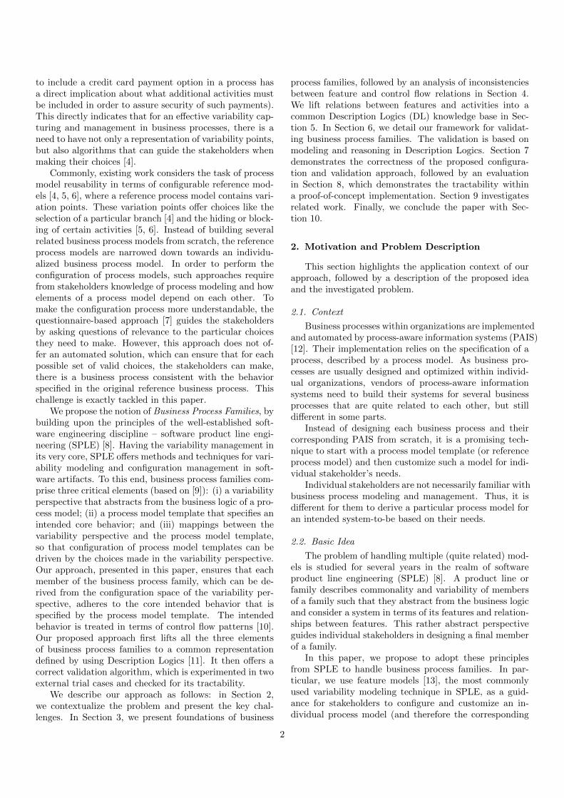
Figure 2: Members of a business process family are derivedby feature selection from a business process family model
2.3. Investigated Problem
As depicted in Figure 1, a business process family isrepresented by a feature model, a process model templateand mappings between features and activities. A particu-lar member of the family, i.e., a process model is derivedby selecting features of the feature model. This procedureis illustrated in Figure 2.
In the scope of this paper, we consider business process
3
models at the modeling perspective, i.e., we analyze andconfigure business process models at design time (modelingtime), and we do not take into account run time aspects. Aparticular configured business process model is still at themodeling perspective, but the set of permitted executionsmight be restricted compared to the original process modeltemplate.
Since the configuration of particular business processmodels is based on feature selections, the business processmodel is influenced by two kinds of constraints or rela-tions: (i) The selection of features might depend on theselection of other features according to feature relations.This dependency between features is carried to the corre-sponding activities of the business process model by map-pings. (ii) Activities of the business process model dependon other activities regarding to the control flow relations.
Business process models that are configured accord-ing to feature selections (and therefore according to thefeature relationships) do not necessarily satisfy the con-trol flow relations of the given process model template.For instance, activity Send Notification is mapped to thefeature Emails that characterizes a notification via email.The sibling activity Display Selection is mapped to thefeature User Board, referring to a notification via the userboard. Thus, a stakeholder could build a valid feature se-lection (regarding to feature relations) that contains onlyone of these features, leading to a business process modelthat only contains one of these activities (Send Notifica-tion or Display Selection), while both require each otheraccording to their control flow relations.
We suggest to address the comparison of relationshipsin the process model template with the relationships ofthe corresponding mapped features in the feature modelin order to ensure that each valid feature selection leadsto a business process model that adheres to the control flowrelations that are given by the process model template.
3. Business Process Families
This section formally defines business process familiesand their three constitutive elements.
3.1. Feature Models
The most common means for representing variabilityare feature models. A feature model is a tree-like structurewhose nodes are features of the target software productline 1 [14]. It describes valid combinations of features. Ac-cording to the distinction of Metzger et al. [15], variabilityused in our case can be considered as software variability,i.e., the ability to customize a system in a particular case.
In a feature model, there exists three kinds of rela-tionships between features: 1) parent-child relationships;
1In this paper, we will use product line and software family inter-changeably, even though one can argue that they can not be consid-ered synonymous.
2) group relationships; and 3) cross-tree constraints alsoknown as integrity constraints.
A formal description of feature models is given in Def-inition 1. Parent child relationships are mandatory andoptional. A mandatory parent-child relationship specifiesthat if a parent feature is selected in a certain config-uration, its mandatory child feature has to be selected,too (e.g., Store Front-End and Store Back-End are bothmandatory children of E-Shop). This is depicted by therelation FM in Definition 1, where the set F refers to theparent features and the power set P(F) denotes the setof mandatory child features. An alternative feature group,or xor feature group, (e.g., Basic and Advanced), specifiesthat when their parent feature is selected, exactly one ofthe members of the group can be selected. Finally, an orgroup (e.g., Emails, User Board and Web Page) defines aset of features from which at least one has to be selected.
Integrity or cross-tree constraints between features arethe ones that cannot be captured by the tree structureof feature diagrams. Generally, two cross-tree constraintsexist, namely includes and excludes. Includes means thatif an including feature is in a configuration, the includedfeature has to be as well (e.g., New User and Registration).Excludes is the opposite to includes.
Definition 1 (Feature Model). A feature model Φ =〈F , FM , FO, FIOR, FXOR, Fincl, Fexcl〉 is a tree struc-ture that consists of features F . FM ⊆ F × P(F) andFO ⊆ F × P(F) are sets of parent features and the setof all their mandatory and optional child features, respec-tively. FIOR ⊆ F ×P(F) and FXOR ⊆ F ×P(F) are setsof pairs of child features and their common parent feature.Finally, Fincl ⊆ F × F and Fexcl ⊆ F × F are sets ofincludes and excludes relationships (integrity constraints).
3.2. Process Model Template
A process model template specifies the business logicperspective. In Figure 1, we use BPMN to specify a pro-cess model template. Such a template typically consistsof process patterns like subprocesses, activities and gate-ways. We understand a process model template as a di-rected graph, according to Definition 2.
Definition 2 (Process Model Template).A process model template is a directed graph ΩG = 〈V, E〉with V denoting a finite set of vertices and E the edgesbetween the vertices describing the flow of the process.
• V consists of a set of activities A and a disjoint setof gateways (or control vertices) G and exactly onestart and one end vertex (V = A ] G).
• Activities have exactly one incoming and one outgo-ing edge.
• Gateways have either exactly one incoming and atleast two outgoing edges or exactly one outgoing edgeand at least two incoming edges. The first ones refer
4
to opening gateways (decision / fork gateways) andthe second ones to closing gateways (merge / joingateways).
According to the BPMN specification [16], activities(A) are either atomic activities or sub-processes (decom-posable activities).
We focus in our work on structured process models fortwo reasons. Firstly, for the class of structured models,structural constraints coincide with behavioral constraints(see the work on behavioral profiles that are derived fromprocess structure trees [17]). Secondly, there are tech-niques to derive structured models for a broad class of un-structured models [18]. Structured models require that foreach opening gateway there is a closing gateway, i.e., theycreate valid single-entry-single-exit (SESE) fragments.
Definition 3 extends the definition of process modeltemplate ΩG towards structured process model templates,where for each opening gateway there is a correspondingclosing gateway. Thus, a process model can be decom-posed into SESE fragments.
Definition 3 (Structured Process Model Template).A structured process model (or structured process modeltemplate) is triple Ω = 〈V, E , S, D〉, which is based on aprocess model ΩG = 〈V, E〉. The set S explicitly representsSESE fragments of Ω, where each SESE fragment S ∈ Swith S ∈ V ×V ×P(B) has an entry and an exit node anda set of branches (B ∈ B). D is a set of decompositionrelations D ∈ D, where D ⊆ A×A, denoting a subprocessthat contains internal activities.
3.3. Mappings
Mappings (Definition 4) connect features F and activ-ities A of the structured process model template Ω thatimplement the business logic of particular configurations.For example, every configuration that contains the featureBasic, contains the activity Create New List. All activitiesof the process model template that are not mapped to anyfeature are contained in every business process model. Fur-thermore, a feature can be mapped to multiple activitiesand likewise an activity might realize multiple features.Formally, mappings are defined as follows.
Definition 4 (Mapping). For a feature model Φ = 〈F ,FM , FO, FIOR, FXOR, Fincl, Fexcl〉 and a structured pro-cess model template Ω = 〈V, E , S, D〉 with A ⊆ V, a map-ping M is a relation M ⊆ F×A, that is defined as M :=(f, a) : f ∈ F ∧ a ∈ A.
3.4. Business Process Families
The combination of feature models Φ, structured pro-cess model templates Ω and mappings M constitute a busi-ness process family model.
Definition 5 (Business Process Family Model). Fora feature model Φ = 〈F , FM , FO, FIOR, FXOR, Fincl,
Fexcl〉, a structured process model template Ω = 〈V, E , S,D〉 with A ⊆ V and Mappings M ⊆ F ×A between bothmodels a business process family model Ψ = 〈Φ,Ω,M〉 isthe combination of them.
4. Inconsistencies in Business Process Families
The feature model describes variability relationshipsamong selectable features of a system-to-be, the processmodel template represents control flow relationships thatare required to be satisfied by all family members. Controlflow relations are imposed by control flow patterns, as de-scribed in [10, 19, 20]. In business process family models,mappings combine features and activities. Thus, featuresand activities might be affected by different relationships.
4.1. Mapping Influence on Control Flow Relations
In our representation formalism for business processfamilies, the intention is that the selection of a featuredetermines whether the corresponding mapped activity ispart of the particular business process model or not. Ob-viously, the resulting business process model is built ac-cording to feature relations, but they do not necessarilycoincide with the control flow relations given by the tem-plate.
As already outlined, our approach aims at detectinginconsistencies between feature relationships and controlflow relationships, based on a comparison of the differ-ent relationships of mapped features and activities. Whilethe kinds of relations in the feature model are explicitlygiven by feature groups (and, ior and xor), as well as byintegrity (cross-tree) constraints, we have to identify thekinds of relationships between activities in the businessprocess model.
Following this line of argumentation, the focus in theremainder of this section is on an analysis of control flowpatterns as best practise building blocks for process mod-els. For each pattern, we discuss which kind of control flowrelationship is imposed to activities, and whether this rela-tionship is influenced by feature relationships if activitiesare mapped to features.
4.1.1. Basic Control Flow Patterns
The basic control flow patterns provide fundamentalmodeling primitives for business processes. They are sum-marized in [10, 19, 20] and are imposed by business processmodeling languages like BPMN.
Sequence. The sequence is a basic construct to describethe sequential routing of activities. An activity can be ex-ecuted after the execution of its predecessor activity. Se-quences restrict the ordering of activities, but the existenceand co-existence is not required by a sequential ordering(cf. [21]). Thus, in our configuration context, no featurerelation influences the ordering of activities and we canneglect sequences in the remainder of this work.
5
Parallel Branching. If activities occur in parallel branches,they have to be executed commonly, i. e., if an activity ofthe first branch is executed, then also the activity of thesecond branch is executed.
Parallel branchings are started by parallel opening gate-ways, while they can be closed by several allowed types ofclosing gateway. In general, a parallel branching is closedby a closing parallel gateway. In our configuration context,activities in all these parallel sibling branches represent aconjunctive relation in the logical sense.
Exclusive Branching. Activities that appear in exclu-sive sibling branches are supposed to be exclusive, i. e., it isnot allowed to execute activities from alternative branchesin a process execution.
Subprocess. BPMN models facilitate decomposition ofactivities into subprocesses. The configuration of particu-lar business process models allows for a certain degree offreedom as to whether an activity within a subprocess isselected. However, if an internal activity is part of a partic-ular business process model its corresponding subprocesshave to be part of this business process model, too.
4.1.2. Advanced Branching and Synchronization Patterns
Advanced branching and synchronization pattern of-fer constructs for a more concise representation of processmodels, but they can be reduced to equivalent constructsthat only use basic patterns.
Inclusive Branching. Inclusive branches offer executionchoices in which at least one branch has to be executed. Incontrast to exclusive branching, multiple sibling branchescan be executed. This kind of constraint is imposed forall activities within sibling branches in every particularconfiguration of a business process model.
Discriminator and N out of M Join. The discrimi-nator and the n out of m join are special joins that facil-itate a kind of race situation between different incomingbranches [16]. The successors of the gateway are enabledfor execution if at least one predecessor is executed (in caseof a discriminator) or at least n (in case of an n out of mjoin) is/are executed.
In our case, as we assume a correct process model tem-plate and we remain at the modeling perspective. Thecrucial aspect of these complex joins for the configurationis to ensure the minimum number of predecessors in orderto stick to the meaning that is given by a discriminatorand n out of m join.
4.1.3. Structural Patterns
The focus of our work is on the structural description ofprocesses using process models. Structural patterns allowfurther specification of the process behavior in a processmodels. They capture the structure of loops and explicitstatements about the termination of process executions.
Arbitrary Cycles. In contrast to structural cycles, ar-bitrary cycles (or unstructured loops) describe loops withmultiple entry or exit points. With regard to mappinginconsistencies, there is no distinction between structuraland arbitrary cycles. Arbitrary cycles can be reduced tostructured cycles, as demonstrated in [10]. Cycles are com-posed of branchings, where some of the branches return tothe part of the process that needs to be repeated. There-fore, we treat branches of arbitrary cycles like inclusivebranchings in our approach.
Implicit Termination. An explicit termination is rep-resented in a process model by an end event (i. e., an endnode in the process model). Implicit termination statesthat each subprocess should terminate if there is no fur-ther activity to execute, i. e., without an explicit end nodeafter the last activity of a subprocess.
As the particular purpose of our validation is on therelations between activities and implicit termination doesnot impose any constraints or relations between activities,implicit termination will not cause any inconsistency dur-ing the process model configuration. However, we assumethat if the last activity of a (sub-) process is removed andthere is no explicit end event, the predecessor of the re-moved element is considered as the last activity with re-spect to implicit termination.
4.1.4. Multiple Instances (MI) Patterns
Multiple instances patterns describe the situation whenthere are multiple instances of an activity active. This israther an implementation oriented aspect for the processmanagement system. BPMN supports three multiple in-stances pattern: (i) MI without synchronization allows foran activity to have multiple instances within one processexecution; (ii) MI with a priory design time knowledge pro-vides the possibility to have a fixed number of instancesof an activity within one process, whereby the number isalready known at design time; while the pattern (iii) MIwith a priory runtime knowledge enables a variable num-ber of instances, but the number is known at runtime. InBPMN, these patterns are represented as annotations ofactivities. As every runtime instance of a process is a copyof the process depicted in a model, therefore, if the processmodel does not have inconsistencies, neither its instanceswill have.
4.1.5. State-based Patterns
Deferred Choice. This pattern is related to an exclusivebranching, but the choice of the exclusive opening gate-way is made explicitly, i. e., it is not based on control flowdecisions. Once one branch of a deferred choice is exe-cuted (i. e., at least the first activity of this branch is exe-cuted), the remaining sibling branches are withdrawn forexecution. This pattern is rather relevant for the processexecution.
6
Interleaved parallel routing. This pattern enables aset of activities to be executed in an arbitrary order. Theexecution order of these activities is decided at runtime,but at any time only one activity can be executed. Theconfiguration at design time does not affect this pattern,as the selection is done at runtime.
Milestone. This pattern is an explicit statement that anactivity cannot be executed unless a certain specified stateis reached. It is a dependency between between activities,but it is rather a test of certain (state) conditions than acontrol flow dependency. Thus, this pattern is not affectedin our configuration.
4.1.6. Cancellation Patterns
The cancellation patterns enable the cancellation of anactivity (cancel activity) or of a complete process instance(cancel case). In both patterns, an activity (or a processinstance) that is enabled can be withdrawn before the ex-ecution. This pattern is meaningful if there are multipleinstances of an activity (or of a process) and in case oneinstance has executed a certain activity (or a certain partof the process) further executions have to be avoided. Asboth cancellation patterns are relevant for process execu-tions and not in the modeling perspective, they are notaffected within our feature-based configuration approach.
4.2. Relationships and Inconsistencies
Mappings between features and activities connect dif-ferent relationships of the mapped elements. Usually, do-main experts map features to activities of a process modeltemplate to link variability and control flow relations fromdifferent views. However, the relationships (or constraints)of the mapped features and activities do not necessarilycoincide with each other, or they might be even contra-dictory. From a logical point of view, we deal with basiclogical connectives, as described in Definition 6.
Definition 6 (Relationships between Elements).Control flow relations CR describe relationships betweenactivities Aj ∈ A (of a structured process model templateΩ) and feature relations FR describe relationships betweenfeatures Fi ∈ F (of a feature model Φ). We refer toelements in these relationships in the terms of predicatelogics: (1) conjunctive connected elements are called con-juncts, (ii) disjunctive (inclusive or exclusive) elementsare called (inclusive or exclusive) disjuncts, and (iii) im-plications have elements as antecedents and consequences.
The key focus of our work is to represent and comparerelations of features and activities, according to the logicalconnectors of Definition 6. We follow mapping principlesbetween features and activities in our validation [22].
In the following, we assume a business process familymodel Ψ = 〈Φ,Ω,M〉 that consists of a structured processmodel template Ω = 〈V, E , S, D〉 (A ⊆ V), a featuremodel Φ = 〈F , FM , FO, FIOR, FXOR, Fincl, Fexcl〉 andmappings M (M ⊆ F ×A).
Store Front-End
Searching Registration
E-Shop
Basic Advanced
WishList
Retrieve List From
Server
Retrieve Local List
Create New List
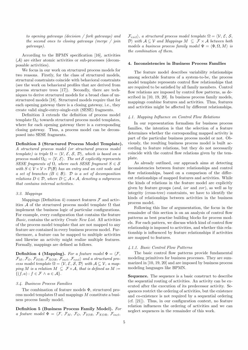
Figure 3: Strong inconsistency due to exclusive branchingmismatch
In a comparison of the feature relations (FR) and therelations given by the control flow relations (CR) onlymapped elements are relevant since unmapped element cannot be involved in contradicting relations, given that wealways assume correct feature models and correct processmodel templates.
Definition 7 (Strong Inconsistency). Assume a con-trol flow relation CR on activities A1, . . . , An ∈ A anda feature relation FR on F1, . . . , Fm ∈ F , and mappings(Fi, Aj) ∈ M of some features Fi (i ∈ 1, . . . ,m) andactivities Aj (j ∈ 1, . . . , n). A strong inconsistency be-tween FR and CR occurs if there is no feature selectionpossible that leads to non-contradicting control flow rela-tions of activities in CR.
Figure 3 depicts a strong inconsistency of activities inexclusive sibling branches. The activities Retrieve ListFrom Server and Create New List appear in exclusive sib-ling branches. We require that there is no contradictingperspective in the feature model that would suggest (andalso allow) feature configurations that contradict to theexclusive behavior, as it is imposed by the process modeltemplate. The inconsistency in Figure 3 is due to the map-ping of these activities to the features Basic and Advancedthat can only appear together in each possible feature con-figuration, i.e., either both features are selected or none ofthem.
A weaker notion is the potential inconsistency. Thereare feature selections allowed in FR that lead to contra-dicting execution combinations of activities in CR. Obvi-ously, each strong inconsistency is also a potential incon-sistency.
7
Emails UserBoard
Web Page
Store Back-End
Order Processing
Display Notification
E-Shop
WishList
Send Notification
DisplaySelection
StoreSelection
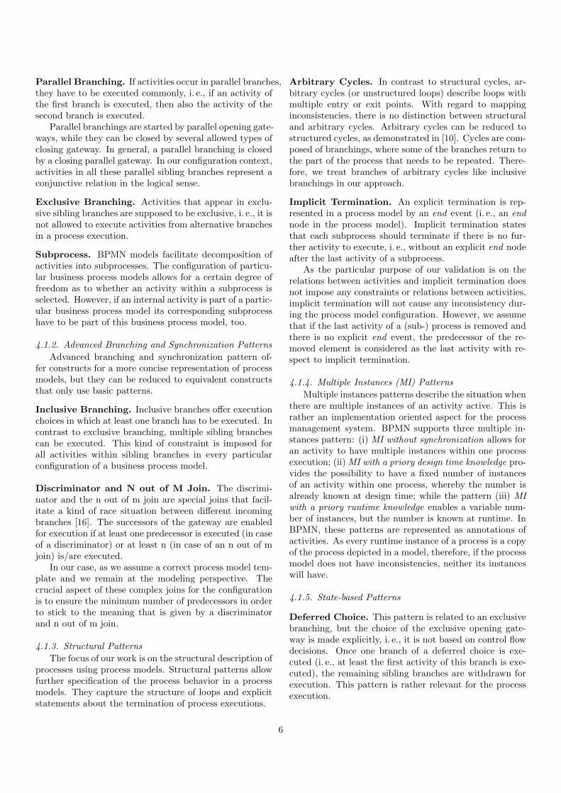
Figure 4: Potential inconsistency due to parallel branching
Figure 4 depicts an example for a potential inconsistencydue to mappings between features that are (inclusive) or-siblings (Emails and User Board) and activities in parallelbranches. Thus, a feature selection does not guaranteethat all activities in parallel branches (Send Notificationand Display Selection) occur together in a business processmodel. However, this is imposed by the process modeltemplate.
Definition 8 (Potential Inconsistency). Assume acontrol flow relation CR on activities A1, . . . , An ∈ A anda feature relation FR on F1, . . . , Fm ∈ F , and mappings(Fi, Aj) ∈ M of Fi (i ∈ 1, . . . ,m) and activities Aj
(j ∈ 1, . . . , n). A potential inconsistency means therecan be a feature selection within FR that result in acontradicting control flow relation of activities in CR.
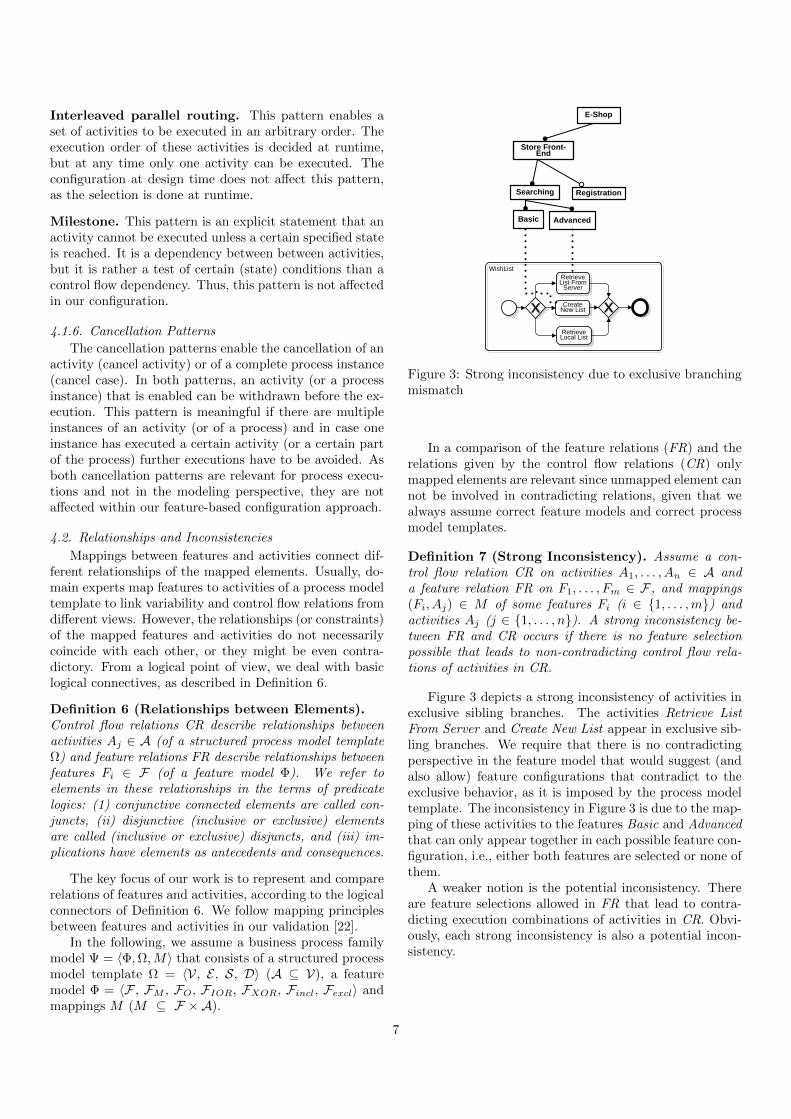
Figure 5 depicts another example of a potential inconsis-tency. The subprocess WishList is mapped to an optionalfeature Registration, while an internal activity RetrieveList From Server is mapped to the feature Advanced andAdvanced is a mandatory child feature of feature Search-ing. The selection of feature Store Front-End requires theselection of its mandatory child Searching and thereforealso the selection of Advanced, but the feature Registrationis not necessarily selected. Thus, the subprocess Wish-List, which is mapped to the optional feature Registration,is removed, while at the same time the internal activityRetrieve List From Server should remain in the businessprocess model.
WishList
Store Front-End
Searching Registration
Basic Advanced
Retrieve List From
Server
Create New List
Figure 5: Potential inconsistency due to potential removalof the subprocess WishList, while the activity Retrieve ListFrom Server is not removed
4.3. Overview of Inconsistencies
Table 1 summarizes the interrelationships between fea-ture relationships and control flow relationships. We usefour symbols to indicate whether we can identify an in-consistency or not: (i) ‘X’ indicates no inconsistency be-tween feature relations FR and control flow relations CR,(ii) strong inconsistencies are denoted by ‘ ’, (iii) the sym-bol ‘±’ refers to potential inconsistencies, and (iv) if ourapproach cannot lead to inconsistencies at the modelinglevel based on a mapping between features and activities,the corresponding cells are marked with ‘−’.
The comparison between feature and control flow rela-tions in Table 1 refers to the following relations between el-ements: (i) Feature relations among sibling features (and,xor, ior) are logical connection among conjuncts or dis-juncts. (ii) Integrity constraints of features (includes andexcludes) are implications (and negations) from a featureas antecedent to a feature as consequent.
(iii) Branching patterns of the control flow patterns,the deferred choice and interleaved parallel routing pat-tern denote a logical combination of conjuncts or disjuncts,which are activities of sibling branches. (iv) The relationsin a subprocess depicts an implications from a logical pointof view. If we compare two implications, we mean the situ-ation that the antecedents are mapped to each other, andlikewise the consequences. Other combinations have noinfluence on the inconsistency in our approach.
5. Knowledge Base for Business Process Families
According to Section 4, the basic idea of our approachis to compare relationships between elements of both mod-els. Thus, a knowledge base has to cover the featuremodel in terms of feature relations, the process model tem-plate by control flow relations, and mappings between both
8
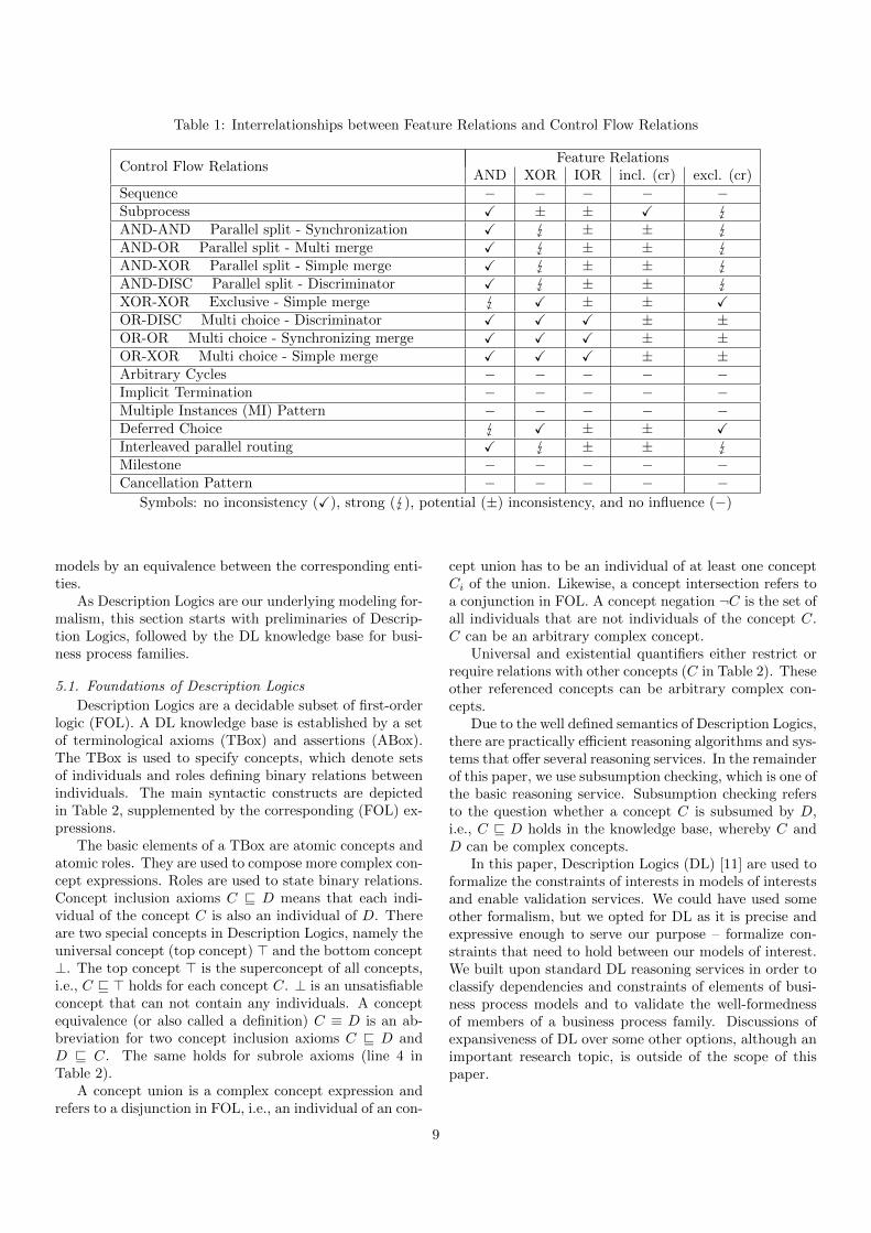
Table 1: Interrelationships between Feature Relations and Control Flow Relations
Control Flow RelationsFeature Relations
AND XOR IOR incl. (cr) excl. (cr)Sequence − − − − −Subprocess X ± ± X AND-AND Parallel split - Synchronization X ± ± AND-OR Parallel split - Multi merge X ± ± AND-XOR Parallel split - Simple merge X ± ± AND-DISC Parallel split - Discriminator X ± ± XOR-XOR Exclusive - Simple merge X ± ± XOR-DISC Multi choice - Discriminator X X X ± ±OR-OR Multi choice - Synchronizing merge X X X ± ±OR-XOR Multi choice - Simple merge X X X ± ±Arbitrary Cycles − − − − −Implicit Termination − − − − −Multiple Instances (MI) Pattern − − − − −Deferred Choice X ± ± XInterleaved parallel routing X ± ± Milestone − − − − −Cancellation Pattern − − − − −
Symbols: no inconsistency (X), strong ( ), potential (±) inconsistency, and no influence (−)
models by an equivalence between the corresponding enti-ties.
As Description Logics are our underlying modeling for-malism, this section starts with preliminaries of Descrip-tion Logics, followed by the DL knowledge base for busi-ness process families.
5.1. Foundations of Description Logics
Description Logics are a decidable subset of first-orderlogic (FOL). A DL knowledge base is established by a setof terminological axioms (TBox) and assertions (ABox).The TBox is used to specify concepts, which denote setsof individuals and roles defining binary relations betweenindividuals. The main syntactic constructs are depictedin Table 2, supplemented by the corresponding (FOL) ex-pressions.
The basic elements of a TBox are atomic concepts andatomic roles. They are used to compose more complex con-cept expressions. Roles are used to state binary relations.Concept inclusion axioms C v D means that each indi-vidual of the concept C is also an individual of D. Thereare two special concepts in Description Logics, namely theuniversal concept (top concept) > and the bottom concept⊥. The top concept > is the superconcept of all concepts,i.e., C v > holds for each concept C. ⊥ is an unsatisfiableconcept that can not contain any individuals. A conceptequivalence (or also called a definition) C ≡ D is an ab-breviation for two concept inclusion axioms C v D andD v C. The same holds for subrole axioms (line 4 inTable 2).
A concept union is a complex concept expression andrefers to a disjunction in FOL, i.e., an individual of an con-
cept union has to be an individual of at least one conceptCi of the union. Likewise, a concept intersection refers toa conjunction in FOL. A concept negation ¬C is the set ofall individuals that are not individuals of the concept C.C can be an arbitrary complex concept.
Universal and existential quantifiers either restrict orrequire relations with other concepts (C in Table 2). Theseother referenced concepts can be arbitrary complex con-cepts.
Due to the well defined semantics of Description Logics,there are practically efficient reasoning algorithms and sys-tems that offer several reasoning services. In the remainderof this paper, we use subsumption checking, which is one ofthe basic reasoning service. Subsumption checking refersto the question whether a concept C is subsumed by D,i.e., C v D holds in the knowledge base, whereby C andD can be complex concepts.
In this paper, Description Logics (DL) [11] are used toformalize the constraints of interests in models of interestsand enable validation services. We could have used someother formalism, but we opted for DL as it is precise andexpressive enough to serve our purpose – formalize con-straints that need to hold between our models of interest.We built upon standard DL reasoning services in order toclassify dependencies and constraints of elements of busi-ness process models and to validate the well-formednessof members of a business process family. Discussions ofexpansiveness of DL over some other options, although animportant research topic, is outside of the scope of thispaper.
9

Table 2: Constructs and Notations in DL and FOL Syntax
Construct Name DL Syntax FOL Syntax
atomic concept C C(x)atomic role R R(x, y)concept inclusion axiom C v D ∀x.C(x)→ D(x)role inclusion axiom R v S ∀x, y.R(x, y)→ S(x, y)concept union C1 t . . . t Cn C1(x) ∨ . . . ∨ Cn(x)concept intersection C1 u . . . u Cn C1(x) ∧ . . . ∧ Cn(x)concept negation ¬C ¬C(x)universal quantification ∀P.C ∀y.(P (x, y)→ C(y))existential quantification ∃P.C ∃y.(P (x, y) ∧ C(y))
5.2. Feature Relationships
We represent feature relations in a DL knowledge baseΣΦ. The DL representation is based on the general model-ing principles of Wang et al. [23]. However, the purpose ofthe work of Wang et al. is on validation of feature modelconfigurations, while our target is an analysis of constraintinfluence of mapped goals to potential feature model con-figurations. Thus, we adapt some modeling principles ac-cording to our particular validation purpose.
For each feature F , we introduce a DL concept CF , re-ferred to as constraint concept of F . This concept collectsall relationships how feature F is related to other features.The DL representation is depicted in Algorithm 1.
We use only one role requires to describe the relationsof a feature that requires other features, while Wang et al.use different roles. It is easier and more intuitive to com-pare concept expressions that use the same role. We useconcept definitions (equivalence axioms) in order to allow asubsumption checking between the different concepts thatrepresent feature and control flow relations (cf. validationprinciples in Section 6).
In case a feature Fi is a mandatory child feature (lines 4–6), it is in an and relationship with its siblings in the logicalsense, since we know that the selection of one mandatorysibling also requires the selection of all other mandatorysibling features. Thus, we add this conjunctive relation tothe concept CFi for each mandatory sibling feature Fi.
An inclusive or decomposition of a feature F into fea-tures F1, . . . , Fn is represented by a concept union overthe sibling features of the or decomposition (lines 7–9). Adisjunctive connection is added to the concept descriptionCFi
of each sibling feature Fi.Likewise, exclusive or decomposition are described by
concept unions. However, we need a further restrictionthat the selection of only one feature is allowed. Thisis described in the second part of the concept expression(line 10–12).
The includes integrity constraint specifies that the se-lection of a feature F also requires the selection of anotherfeature F ′. In DL, we define CF dependent on the fea-ture F ′ (lines 13–15). The excludes integrity constraintis defined similarly (lines 16–18). The concept negationexpresses the exclusiveness of features F and F ′.
Algorithm 1 Representation of the Feature ModelKnowledge Base ΣΦ
1: Input: 〈F ,FM ,FIOR,FXOR,Fincl,Fexcl〉2: ΣΦ := ∅.3: for all F ∈ F do4: for all (F, F1, . . . , Fn) ∈ FM do5: CFi
:= CFiud
i=1,...,n ∃requires.Fi
6: end for7: for all (F, IOR, F1, . . . , Fn) ∈ FIOR do8: CFi := CFi u
⊔i=1,...,n ∃requires.Fi
9: end for10: for all (F,XOR, F1, . . . , Fn) ∈ FXOR do11: CFi
:= CFiu (
⊔F ′∈F1,...,Fn ∃requires.F
′
u¬(⊔
F ′′,F ′′′∈F1,...,Fn (∃requires.F ′′ u∃requires.F ′′′))
12: end for13: for all (F, F ′) ∈ Fincl do14: CF := CF u ∃requires.F ′15: end for16: for all (F, F ′) ∈ Fexcl do17: CF := CF u ¬∃requires.F ′18: end for19: ΣΦ := ΣΦ ∪ CF
20: end for
Features and their relations to other features are rep-resented by concept definitions F and CF . An excerpt ofthe e-store feature model is presented in Axioms 1 – 3.
CStoreFront-End ≡ ∃ requires.StoreFront− End
u ∃ requires.StoreBack − End (1)
CEmails ≡ ∃ requires.Emails t ∃ requires.UserBoard
t ∃ requires.WebPage (2)
CNewUser ≡ ∃ requires.Registration (3)
Axiom 1 defines StoreFront-End and StoreBack-Endas conjunctive related elements, expressed by a constraintconcept CStoreFront-End. The same constraint concept isused for the feature StoreBack-End. We use the role re-quires to describe this relationship. There is no such axiomfor optional features.
10

Algorithm 2 Representation of Branching Fragments inΣΩ
1: Input: Ω = 〈V, E ,S,D〉2: RelA ≡ >3: for all S ∈ S do4: if S = (and, and,B) ∨ S = (and, or,B) ∨ S =
(and, xor,B) ∨ S = (and, disc,B) then5: CAi := CAi u
dBj∈B ∃ requires.(
⊔Ak∈BJ
Ak)6: end if7: if S = (ior, ior,B) ∨ S = (ior, disc,B) ∨ S =
(ior, xor,B) then8: CAi
:= CAiu⊔
Bj∈B ∃ requires.(⊔
Ak∈BJAk)
9: end if10: if S = (xor, xor,B) then11: CAi := CAi u (
⊔Bj∈B ∃ requires.(
⊔Ak∈BJ
Ak))
u¬(d
Bj∈B ∃ requires.(⊔
Ak∈BJAk))
12: end if13: ΣΩ := ΣΩ ∪ CAi
14: end for
For inclusive and exclusive disjuncts, a concept unionis used. For instance, Axiom 2 defines Emails, User Boardand Web Page as disjuncts. The same constraint conceptis built for features User Board and Web Page. The axiomensures that at least one feature is selected. Axiom 3 de-picts an integrity constraint where the feature New Userincludes Registration. For integrity constraints, we use thesame role requires. At the end, there is one single conceptdefinition for each feature that contains all relationshipsof this feature.
The feature model representation in DL is different tothe modeling principles of Wang et al. [23] due to the dif-ferent scope of our validation. We are not interested inthe validation of a particular feature configuration withrespect to a given feature model. Instead, our focus is thevalidation of the process model template in which the rela-tions of particular features of the feature model are takeninto account. We use concept definitions to define featurerelationships in order to ease the comparison. Further-more, we only use one role requires, which also simplifiesthe relationship comparison for our validation purpose.
5.3. Control Flow Relationships
We represent business process model templates in termsof control flow relations CR between activities. Algorithm 2describes how the corresponding knowledge base ΣΩ isbuilt.
There might be an overlapping of activity relations.Accordingly, we build relations of activities CA as a con-junction (intersection in DL) of activities from the differentcontrol flow patterns. Initially, each relation concept CA
is defined as equivalent to the universal concept > (line 2).In lines 4–6, the algorithm restricts the concept defini-
tions CAi, in which Ai are activities in parallel branches.
We use an intersection between activity sets of sibling
Algorithm 3 Subprocess Representation in ΣΩ
1: Input: ΣΩ
2: for all D ∈ D do3: if (Asub, Ainner) ∈ D then4: CAinner := CAinner u ∃requires.Asub
5: ΣΩ := ΣΩ ∪ CAinner
6: end if7: end for
branches, indicating the conjunctive relationship betweensibling activities in parallel branches. From a logical pointof view, we treat different closing gateways (multiple merge,synchronization and discriminator) equally. Branching re-lations do not impose restrictions on activities within thesame branch in a fragment (in contrast to the sequencepattern). Thus, we describe all activities within the samebranch by a concept union, independent of the kind ofbranching.
Multi choices are treated in lines 7–9, including syn-chronizing merge, simple merge and discriminator. Logi-cally, activities of sibling branches are connected by a con-cept union. In case of exclusive branchings (lines 10–12),the concept definitions CAi
contain a further restrictionthat allows only the execution of one branch. Like in fea-ture models, this is expressed by a concept negation (¬).In both cases, activities of the same branch are treated likein the parallel case, i.e., they are represented by a conceptunion since ior and xor relations refer to activities of sib-ling branches, but not to activities in the same branch.
Algorithm 3 extends the constraint concepts CA of ac-tivities A that are subprocesses, i. e., they are decomposedinto subactivities. The input is the result of the Algo-rithm 2. In this case, we require that if a particular con-figured business process model that contains an internalsubactivity of A then A must be in the business processmodel as well.
The following axioms illustrate the DL representationof the control flow relations from the introduced exampleof Figure 1. Axiom 4 depicts the conjunctive relation-ships between activities Display Selection, Send Notifica-tion and Store Selection, represented by the concept ex-pression CDisplaySelection. The constraint concepts for theother activities (CSendNotification and CStoreSelection) arethe same.
Axiom 5 depicts the disjunctive connection of a choicewith two branches, whereby the first branch contains ac-tivities Enter Name and Save Name and the second theactivities Enter UserID and Save UserID. The disjunctiveconnection refers to activities of sibling branches, but notto activities within the same branch. Activities of the samebranch are represented as a union (second part of the ax-ioms). This representation of predecessors and successorsof a branch is same for each kind of branching. Obviously,in this representation, the ordering among activities of onebranch is neglected, as it is not influence by a configuration
11
in our case (see sequence pattern in Section 4).
CDisplay Selection ≡ ∃ requires.DisplaySelection
u ∃ requires.SendNotification
u ∃ requires.StoreSelection (4)
CEnterName ≡ ∃ requires.(EnterName t SaveName)
t ∃requires. (EnterUserID t SaveUserID) (5)
6. Inconsistency Detection
In Section 5, we transformed feature models and busi-ness process models, which act as process model templates,into a knowledge base that specifies feature relations FRand control flow relations CR. This section proposes val-idation principles in order to analyze the influence of fea-ture relations on control flow relations according to thecomparison in Table 1 of Section 4.3.
Feature relations FR and control flow relations CR areboth represented by a set of axioms in DL knowledge basesΣΦ and ΣΩ. We assume that the feature model Φ andthe business process model template Ω are correct models.Our validation approach comes into play if features aremapped to activities, describing the realization of featuresby activities in particular business process models.
The validation approach relies on the comparison offeature relations FR and control flow relations CR of mappedfeatures and activities. We use Description Logic reason-ing to test concept subsumption as well as concept satisfi-ability checking to detect inconsistencies between mappedfeatures and activities. Especially for potential inconsis-tencies, DL reasoning is a dedicated mean to compare con-cepts (constraint concepts CF and CA) and distinguish be-tween cases where certain concepts (referring to relations)are unsatisfiable, potential satisfiable or even always sat-isfied.
The transformation of relations to DL in Section 5 isdedicated for concept comparison. All constraint concepts(CF and CA) are defined by DL concept definitions andwe use the same role to express relationships between fea-tures and activities. Finally, a mapping of a feature to anactivity is represented by an equivalence between conceptsof the feature and activity concept in the knowledge base.
So far, we are aware of the idea and modeling capa-bilities to compare relations FR and CR of the knowledgebase. A further consideration is how the relations FR andCR can be compared in order to detect inconsistencies ac-cording to the classification in Table 1. For this purpose,we break down the interrelationships of Table 1 for strongand potential inconsistencies to a comparison between log-ical formulas, represented by constraint concepts in DL:
• A potential inconsistency is detected if the satisfac-tion of the feature relation FR of feature F does notnecessarily imply the satisfaction of the correspond-ing control flow relation CR of activity A. Thus, the
concept CF (feature relations of F ) is not subsumedby CA, which represents the control flow relations ofA.
• A strong inconsistency is recognized by contradict-ing relations of feature F and activity A. Thus, inDL, the intersection of the corresponding constraintconcepts CF and CA is unsatisfiable. This meansthe intersection CF uCA is subsumed by the emptyconcept ⊥.
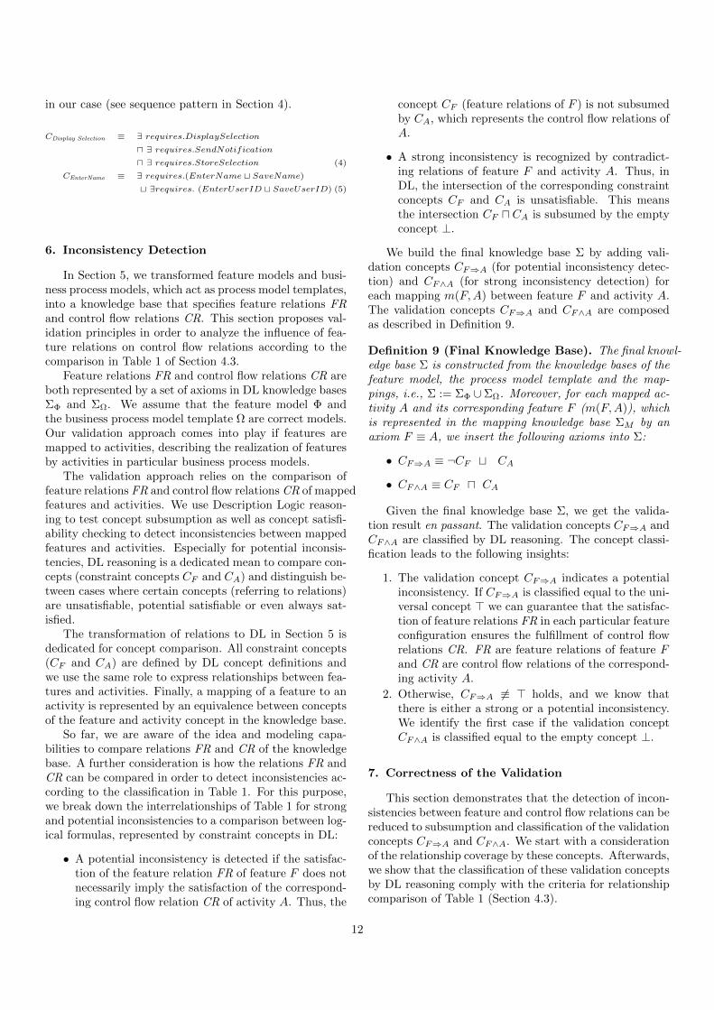
We build the final knowledge base Σ by adding vali-dation concepts CF⇒A (for potential inconsistency detec-tion) and CF∧A (for strong inconsistency detection) foreach mapping m(F,A) between feature F and activity A.The validation concepts CF⇒A and CF∧A are composedas described in Definition 9.
Definition 9 (Final Knowledge Base). The final knowl-edge base Σ is constructed from the knowledge bases of thefeature model, the process model template and the map-pings, i.e., Σ := ΣΦ ∪ΣΩ. Moreover, for each mapped ac-tivity A and its corresponding feature F (m(F,A)), whichis represented in the mapping knowledge base ΣM by anaxiom F ≡ A, we insert the following axioms into Σ:
• CF⇒A ≡ ¬CF t CA
• CF∧A ≡ CF u CA
Given the final knowledge base Σ, we get the valida-tion result en passant. The validation concepts CF⇒A andCF∧A are classified by DL reasoning. The concept classi-fication leads to the following insights:
1. The validation concept CF⇒A indicates a potentialinconsistency. If CF⇒A is classified equal to the uni-versal concept > we can guarantee that the satisfac-tion of feature relations FR in each particular featureconfiguration ensures the fulfillment of control flowrelations CR. FR are feature relations of feature Fand CR are control flow relations of the correspond-ing activity A.
2. Otherwise, CF⇒A 6≡ > holds, and we know thatthere is either a strong or a potential inconsistency.We identify the first case if the validation conceptCF∧A is classified equal to the empty concept ⊥.
7. Correctness of the Validation
This section demonstrates that the detection of incon-sistencies between feature and control flow relations can bereduced to subsumption and classification of the validationconcepts CF⇒A and CF∧A. We start with a considerationof the relationship coverage by these concepts. Afterwards,we show that the classification of these validation conceptsby DL reasoning comply with the criteria for relationshipcomparison of Table 1 (Section 4.3).
12
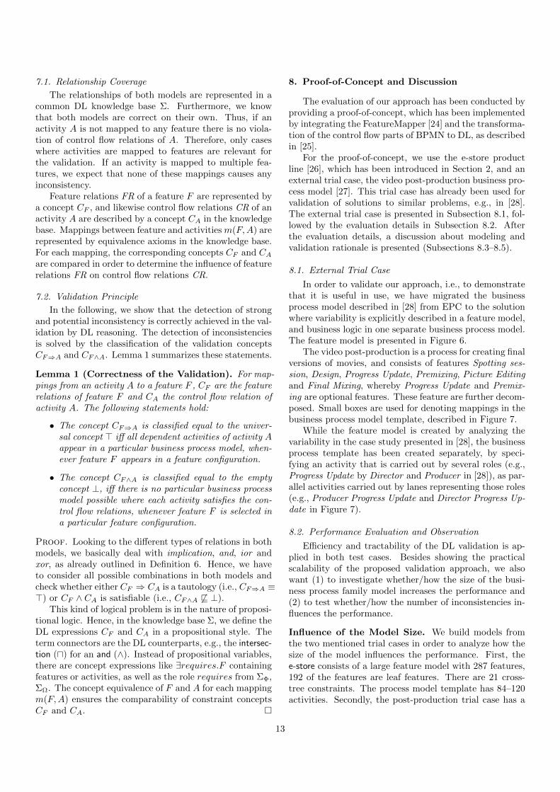
7.1. Relationship Coverage
The relationships of both models are represented in acommon DL knowledge base Σ. Furthermore, we knowthat both models are correct on their own. Thus, if anactivity A is not mapped to any feature there is no viola-tion of control flow relations of A. Therefore, only caseswhere activities are mapped to features are relevant forthe validation. If an activity is mapped to multiple fea-tures, we expect that none of these mappings causes anyinconsistency.
Feature relations FR of a feature F are represented bya concept CF , and likewise control flow relations CR of anactivity A are described by a concept CA in the knowledgebase. Mappings between feature and activities m(F,A) arerepresented by equivalence axioms in the knowledge base.For each mapping, the corresponding concepts CF and CA
are compared in order to determine the influence of featurerelations FR on control flow relations CR.
7.2. Validation Principle
In the following, we show that the detection of strongand potential inconsistency is correctly achieved in the val-idation by DL reasoning. The detection of inconsistenciesis solved by the classification of the validation conceptsCF⇒A and CF∧A. Lemma 1 summarizes these statements.
Lemma 1 (Correctness of the Validation). For map-pings from an activity A to a feature F , CF are the featurerelations of feature F and CA the control flow relation ofactivity A. The following statements hold:
• The concept CF⇒A is classified equal to the univer-sal concept > iff all dependent activities of activity Aappear in a particular business process model, when-ever feature F appears in a feature configuration.
• The concept CF∧A is classified equal to the emptyconcept ⊥, iff there is no particular business processmodel possible where each activity satisfies the con-trol flow relations, whenever feature F is selected ina particular feature configuration.
Proof. Looking to the different types of relations in bothmodels, we basically deal with implication, and, ior andxor, as already outlined in Definition 6. Hence, we haveto consider all possible combinations in both models andcheck whether either CF ⇒ CA is a tautology (i.e., CF⇒A ≡>) or CF ∧ CA is satisfiable (i.e., CF∧A 6v ⊥).
This kind of logical problem is in the nature of proposi-tional logic. Hence, in the knowledge base Σ, we define theDL expressions CF and CA in a propositional style. Theterm connectors are the DL counterparts, e.g., the intersec-tion (u) for an and (∧). Instead of propositional variables,there are concept expressions like ∃requires.F containingfeatures or activities, as well as the role requires from ΣΦ,ΣΩ. The concept equivalence of F and A for each mappingm(F,A) ensures the comparability of constraint conceptsCF and CA.
8. Proof-of-Concept and Discussion
The evaluation of our approach has been conducted byproviding a proof-of-concept, which has been implementedby integrating the FeatureMapper [24] and the transforma-tion of the control flow parts of BPMN to DL, as describedin [25].
For the proof-of-concept, we use the e-store productline [26], which has been introduced in Section 2, and anexternal trial case, the video post-production business pro-cess model [27]. This trial case has already been used forvalidation of solutions to similar problems, e.g., in [28].The external trial case is presented in Subsection 8.1, fol-lowed by the evaluation details in Subsection 8.2. Afterthe evaluation details, a discussion about modeling andvalidation rationale is presented (Subsections 8.3–8.5).
8.1. External Trial Case
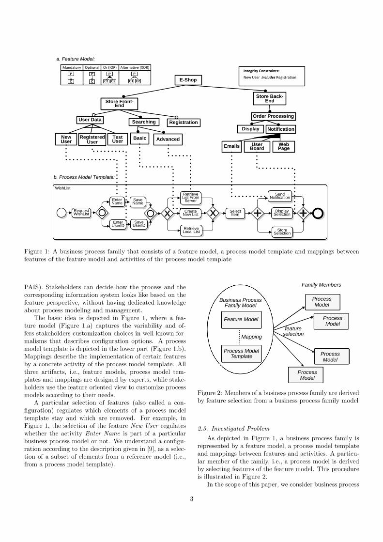
In order to validate our approach, i.e., to demonstratethat it is useful in use, we have migrated the businessprocess model described in [28] from EPC to the solutionwhere variability is explicitly described in a feature model,and business logic in one separate business process model.The feature model is presented in Figure 6.
The video post-production is a process for creating finalversions of movies, and consists of features Spotting ses-sion, Design, Progress Update, Premixing, Picture Editingand Final Mixing, whereby Progress Update and Premix-ing are optional features. These feature are further decom-posed. Small boxes are used for denoting mappings in thebusiness process model template, described in Figure 7.
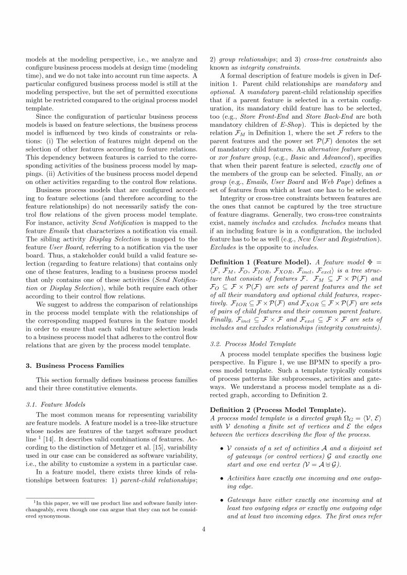
While the feature model is created by analyzing thevariability in the case study presented in [28], the businessprocess template has been created separately, by speci-fying an activity that is carried out by several roles (e.g.,Progress Update by Director and Producer in [28]), as par-allel activities carried out by lanes representing those roles(e.g., Producer Progress Update and Director Progress Up-date in Figure 7).
8.2. Performance Evaluation and Observation
Efficiency and tractability of the DL validation is ap-plied in both test cases. Besides showing the practicalscalability of the proposed validation approach, we alsowant (1) to investigate whether/how the size of the busi-ness process family model increases the performance and(2) to test whether/how the number of inconsistencies in-fluences the performance.
Influence of the Model Size. We build models fromthe two mentioned trial cases in order to analyze how thesize of the model influences the performance. First, thee-store consists of a large feature model with 287 features,192 of the features are leaf features. There are 21 cross-tree constraints. The process model template has 84–120activities. Secondly, the post-production trial case has a
13

Post-Production
Spotting Session
Composer
Sound Designer
Producer
Director
Assistant Director
Design
Music Sound
EditorSound
Designer
PremixingProgress Update
Composer Sound Designer Director Producer Music Sound
Composer ProducerMixerSound
Designer ProducerMixer
Picture Editing
Editor
Negcutter
Final Mixing
Mixer
Composer
Producer
sssd
ssc
ssp
ssd
dmssad pspucds
dse dssd
pusd pm
pmm
pud pup
pmc pmp psm psppssd
fmp
fmc
fmm
fm
pe
pee
pen
pup
Figure 6: Video post-production feature model
Table 3: Validation time for different model sizes withoutinconsistencies
No. Features Activities Mappings Time [msec.]Av. Max.
1 150 84 40 3010 33102 150 84 60 4010 41903 150 120 40 3100 32804 150 120 60 4080 42605 287 84 40 3590 37806 287 84 60 4070 42207 287 120 40 3430 35608 287 120 60 4270 44209 25 15 15 1970 202010 25 23 23 2040 210011 34 15 15 1980 206012 34 23 23 2096 2140
feature model with 34 features and a process model tem-plate with 23 activities.
In both cases, we used multipliers in order to obtain 48different business process family models in eight differentsettings (six for each setting) for the e-store trial case, and24 different business process family models (six for eachsetting, four settings) for the video post-production trialcase. The mappings are established manually.
The performance for each setting is depicted in Table 3,No. 1–12. Settings 1–8 refer to the e-store case study andsettings 9–12 describe the results for models based on thevideo post-production trial case.
The result indicates that the size of the business pro-cess family model in terms of features, activities and map-pings has impact on the running time. The number ofmappings has the main impact on the reasoning perfor-
mance. This is quite intuitive since for each mapping weintroduce two validation concepts as complex concept ex-pressions (using concept intersection, union and negation).The reasoner must classify these concepts check whetherthey are equal to the universal or empty concept. As wecan observe, the execution time of our algorithm for thelargest experimented model is less than 4.5 seconds.
Influence of the Number of Inconsistencies. The set-ting with the largest business process family models (No. 8in Table 3) is used in order to test whether the number ofstrong and potential inconsistencies might influence thevalidation time. Table 4 shows the different settings andresults.
Each setting contains six different business process fam-ily models. The setting in the first row is the same as inrow 8 in Table 3. Each business process family model (row1) contains 60 mappings. Obviously, each mapping mightcause an inconsistency of the activity and the mapped fea-ture due to their different relationships. Thus, the idea ofthis test is to manually change only the mappings in eachbusiness process family model (for each setting), such thatsome mappings (0, 20 or 40) might cause inconsistencies.Thus, in each business process family model there are ei-ther 0, 20 or 40 inconsistencies.
This is reflected in each row of Table 4. In row 2, 20 ofthe total 80 mappings cause a potential inconsistencies ofactivities (and their features). In row 3, 20 mappings leadto strong inconsistencies, while each strong inconsistencyis also a potential inconsistency. Row 4 describes settingswith 20 potential and 20 strong (and potential) inconsis-tencies. Row 5 and 6 capture cases with 40 potential and40 strong (and potential) inconsistencies, respectively.
As indicated by the average and maximum validationtime, there are only minor differences regarding the time.This is not surprising as the reasoning algorithms classi-fies for each mapping m(F,A) the corresponding concepts
14

Video Postproduction
Composer Sound Designer Producer DirectorAssistant Director Editor Mixer Negcutter
ComposerSpotting Session
S. DesignerSpotting Session
ProducerSpotting Session
DirectorSpotting Session
A. Director Spotting Session
EditorSound Design
ComposerMusic Design
S. Designer Sound Design
DirectorProgress Update
ComposerProgress Update
S. Designer Progress Update
ProducerProgress Update
ProducerMusic
Premixing
MixerMusic
PremixingComposerMusic
Premixing
ProducerSound
Premixing
MixerSound
PremixingS. Designer
Sound Premixing
EditorPicture Editing
NegcuttingPicture Editing
MixerFinal Mixing
ComposerFinal Mixing
ProducerFinal Mixing
ssc
sssdssp ssd ssad
dm dssd
dse
pucpusd
pup pud
pmm
psm
pmc
pssd
pmp
psp
fmmfmc fmp
pee pen
Figure 7: Video post-production superimposed business process model
15
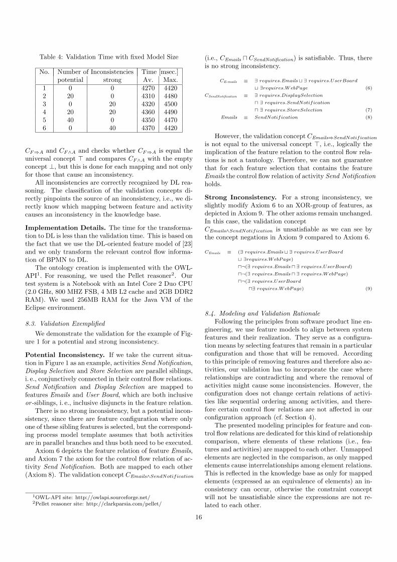
Table 4: Validation Time with fixed Model Size
No. Number of Inconsistencies Time [msec.]potential strong Av. Max.
1 0 0 4270 44202 20 0 4310 44803 0 20 4320 45004 20 20 4360 44905 40 0 4350 44706 0 40 4370 4420
CF⇒A and CF∧A and checks whether CF⇒A is equal theuniversal concept > and compares CF∧A with the emptyconcept ⊥, but this is done for each mapping and not onlyfor those that cause an inconsistency.
All inconsistencies are correctly recognized by DL rea-soning. The classification of the validation concepts di-rectly pinpoints the source of an inconsistency, i.e., we di-rectly know which mapping between feature and activitycauses an inconsistency in the knowledge base.
Implementation Details. The time for the transforma-tion to DL is less than the validation time. This is based onthe fact that we use the DL-oriented feature model of [23]and we only transform the relevant control flow informa-tion of BPMN to DL.
The ontology creation is implemented with the OWL-API1. For reasoning, we used the Pellet reasoner2. Ourtest system is a Notebook with an Intel Core 2 Duo CPU(2.0 GHz, 800 MHZ FSB, 4 MB L2 cache and 2GB DDR2RAM). We used 256MB RAM for the Java VM of theEclipse environment.
8.3. Validation Exemplified
We demonstrate the validation for the example of Fig-ure 1 for a potential and strong inconsistency.
Potential Inconsistency. If we take the current situa-tion in Figure 1 as an example, activities Send Notification,Display Selection and Store Selection are parallel siblings,i. e., conjunctively connected in their control flow relations.Send Notification and Display Selection are mapped tofeatures Emails and User Board, which are both inclusiveor -siblings, i. e., inclusive disjuncts in the feature relation.
There is no strong inconsistency, but a potential incon-sistency, since there are feature configuration where onlyone of these sibling features is selected, but the correspond-ing process model template assumes that both activitiesare in parallel branches and thus both need to be executed.
Axiom 6 depicts the feature relation of feature Emails,and Axiom 7 the axiom for the control flow relation of ac-tivity Send Notification. Both are mapped to each other(Axiom 8). The validation concept CEmails∧SendNotification
1OWL-API site: http://owlapi.sourceforge.net/2Pellet reasoner site: http://clarkparsia.com/pellet/
(i.e., CEmails u CSendNotification) is satisfiable. Thus, thereis no strong inconsistency.
CE-mails ≡ ∃ requires.Emails t ∃ requires.UserBoard
t ∃requires.WebPage (6)
CSendNotification ≡ ∃ requires.DisplaySelection
u ∃ requires.SendNotification
u ∃ requires.StoreSelection (7)
Emails ≡ SendNotification (8)
However, the validation concept CEmails⇒SendNotification
is not equal to the universal concept >, i.e., logically theimplication of the feature relation to the control flow rela-tions is not a tautology. Therefore, we can not guaranteethat for each feature selection that contains the featureEmails the control flow relation of activity Send Notificationholds.
Strong Inconsistency. For a strong inconsistency, weslightly modify Axiom 6 to an XOR-group of features, asdepicted in Axiom 9. The other axioms remain unchanged.In this case, the validation conceptCEmails∧SendNotification is unsatisfiable as we can see bythe concept negations in Axiom 9 compared to Axiom 6.
CEmails ≡ (∃ requires.Emails t ∃ requires.UserBoard
t ∃requires.WebPage)
u¬(∃ requires.Emails u ∃ requires.UserBoard)
u¬(∃ requires.Emails u ∃ requires.WebPage)
u¬(∃ requires.UserBoard
u∃ requires.WebPage) (9)
8.4. Modeling and Validation RationaleFollowing the principles from software product line en-
gineering, we use feature models to align between systemfeatures and their realization. They serve as a configura-tion means by selecting features that remain in a particularconfiguration and those that will be removed. Accordingto this principle of removing features and therefore also ac-tivities, our validation has to incorporate the case whererelationships are contradicting and where the removal ofactivities might cause some inconsistencies. However, theconfiguration does not change certain relations of activi-ties like sequential ordering among activities, and there-fore certain control flow relations are not affected in ourconfiguration approach (cf. Section 4).
The presented modeling principles for feature and con-trol flow relations are dedicated for this kind of relationshipcomparison, where elements of these relations (i.e., fea-tures and activities) are mapped to each other. Unmappedelements are neglected in the comparison, as only mappedelements cause interrelationships among element relations.This is reflected in the knowledge base as only for mappedelements (expressed as an equivalence of elements) an in-consistency can occur, otherwise the constraint conceptwill not be unsatisfiable since the expressions are not re-lated to each other.
16
8.5. Rationale for Description Logics
Description Logics is an expressive language for knowl-edge representation. The semantics of Description Logicsprovides an unambiguous interpretation of expressions inthe knowledge base that is a prerequisite for automatedreasoning. The contribution of Description Logics reason-ing for the validation is threefold:
• We use reasoning to recognize inconsistencies be-tween feature relations and control flow relations.
• Due to the classification of concepts and the sub-sumption checking between concepts, the reasonerdirectly pinpoints the source of an inconsistency, i.e.,which element (feature and activity) is part of an in-consistency. This is crucial in large models, wherevarious mappings exist.
• We use several notions how a reasoner can classifya concept expression in DL, i.e., whether a conceptexpression is always satisfied, is satisfiable or is un-satisfiable. This is exploited in order to distinguishbetween realization equivalence, strong and poten-tial inconsistency.
Compared to other logical formalisms, Description Log-ics is quite efficient in practical settings, is expressive enoughto capture complex feature and process models, and thereis a well established infrastructure for modeling and rea-soning tool support. Description Logics is a decidable sub-set of first-order logic, and the theoretical exponential rea-soning complexity is tractable in practical settings. In con-trast to propositional logics, Description Logics is more ex-pressive and allows the integration of further backgroundknowledge like annotations of elements.
9. Related Work
Due to the increasing need of business processes cus-tomization, several approaches for the development of fam-ilies of business processes have been introduced like Schnie-ders et al. [29], Boffoli et al. [30], La Rosa et al. [31, 7, 32]and van der Aalst et al. [5, 6]. Schnieders et al. [29] modelfamilies of business process models as a variant-rich busi-ness process model. A configuration of such a family isperformed by directly selecting business process elementsof variant-rich processes. In order to support such an ap-proach, Schnieders et al. extend BPMN with concepts formodeling variation. However, in order to perform it, suchan approach requires from a customer knowledge of busi-ness process modeling.
Boffoli et al. [30] and La Rosa et al. [31, 7, 32] also dis-tinguish between business process models and variabilitymodels. Boffoli et al. model problem space as variabilitytable, while La Rosa et al. provide variability by question-naires. They provide guidance to derive valid configura-tions, while our aim is to guarantee that for each possible
and valid feature configuration there is a correspondingvalid process model that satisfies the well-formedness con-straints.
Metzger et al [15] introduce one more approach for rea-soning and configuring variants of variant-rich software.In their approach they distinguish a product line variabil-ity and software variability. Product line variability, cap-tured with the OVM variability modeling language [8, 33]is used to represent members of a product line, i.e., prod-uct planned by the management. Therefore, OVM repre-sents variability within late requirements and design mod-els. Software variability, in Metzger et al.’s approach, cap-tures variability within systems that can be built fromthe existing platform. Our approach uses business pro-cess models to model service oriented systems, and there-fore, corresponds to what Metzger et al. consider softwarevariability.
More similar to our objective is the approach for pro-cess configuration from van der Aalst et al. [5, 6]. Theirframework ensures correctness-preserving configuration of(reference) process models. In contrast to our work, theycapture the variability directly in the workflow net by vari-ation points of transitions. Accordingly, a configuration isbuilt by assigning a value to the transitions, while our ap-proach uses feature selections.
Reinhartz-Berger et al. [34, 35] use a reference mod-eling approach, which is based on the proposed referencemodeling language of Rosemann et al. [4]. Their approachsupports the specification of guidelines and constraintsfor process model configuration. The guidelines and con-straints are represented within the reference model, whichrefers to the process model template in our case. Like inthe previously mentioned approaches, the configuration ofprocess models for a given reference model requires expertknowledge in business process modeling.
Slightly related to our work is the validation approachfor flexible workflows [36], in which a model template of-fers alternatives and constraints impose certain (runtime)restrictions on these alternatives.
Weidlich et al. [17, 21] derive behavior profiles to de-scribe the essential behavior in terms of activity relationslike exclusivity, interleaving and ordering of activities. Aset algebra for behavior profiles is presented in [37]. Thepurpose is to manage several process variants in terms ofset-theoretic relationships. Weber et al. [38] extend pro-cess models by semantic annotations and use them for thevalidation of process behavior correctness that capturescontrol-flow interaction and behavior of activities. In con-trast to our work, their focus is on behavioral constraints,while we consider structural well-formedness constraints.Moreover, our particular emphasis is on the feature-orientedprocess family representation.
A different way of variability management is proposedin terms of specified change operations, as described byHallerbach et al. [39] and Reichert et al. [40]. Likewise,Weber et al. [41, 42] introduced several change patternsto increase process management flexibility, but ensure a
17

certain behavior preservation.In the context of SPLs several approaches have been
introduced, in order to ensure the well-formedness of solu-tion space models. Czarnecki et al. [43] specify constraintson solution space model configurations using OCL con-straints. Problem space models, solution space modelswith OCL constraints, and mappings between them aretransformed to Binary-Decision Diagrams.
Thaker et al. [44] introduce an approach for the verifi-cation of type safety, i.e., the absence of references to un-defined classes, methods, and variables, in solution spacemodels w.r.t. all possible problem space configurations.They specify the models and their relations as proposi-tional formulas and use SAT solvers to detect inconsisten-cies. Janota et al. [45] and van der Storm [46] introduceapproaches to validating the correctness of mappings be-tween feature and component models. They use proposi-tional logics too.
Shobbens et al. [47] provide a generic semantics of fea-ture diagrams that should serve as a basis for implement-ing reasoning procedure. In this paper, due to reuse of thesolution that satisfies our requirements, we reuse the DLrepresentation of feature diagrams introduced by Wang etal. [23]. Our representation is dedicated for the compari-son of relationships between features and activities. Thus,we cover all relationships of a mapped feature by a singlecomplex concept expression.
In addition to the more detailed coverage of all of itsaspects, this paper extends our original approach [48] withadvanced branching patterns, since these patterns frequentlyappear in contemporary business process models. Further-more, a deeper investigation in the tractability evaluationand related work has been conducted.
10. Conclusion
As shown in the related work section, our contributionis primarily related to the modeling and validation of fam-ilies of business processes. While basic ideas of businessprocess families were previously introduced and even cov-ered in our own work [22], there have been very limited(if any) attempts to propose a validation approach of suchfamilies.
Our proposal validates business process models withrespect to their control flow relations; mappings to featuremodels; and dependencies in the feature models. Hence,unlike other approaches on validation of (model-driven)software product lines, our approach also considers thevery nature of business process models through the setof business process practices encoded in control flow re-lations. Even though, in this paper, we used BPMN fordefining the solution space of business process families, ourapproach is easily generalizable to other types of businessprocess modeling languages. This can be deduced fromcontrol flow and branching patterns used in this paper andthe control flow support analyzes presented in the relevantliterature [20].
We evaluated our work with the largest publicly avail-able case study, for which we were able to find both typesof models. Furthermore, we used a further trial case thathas been represented in both feature and business pro-cess models. While these case studies have a realistic size,we would like to have a benchmarking framework, whichwill allow for simulating larger models for business pro-cess families. This is similar to what has been alreadyproposed for feature models [49], but now to be enrichedfor the generation of business process model templates ofdifferent characteristics. We plan to extend our validationformalism towards behavioral constraints in the processmodel template.
References
[1] M. Weske, Business Process Management: Concepts, Lan-guages, Architectures, Springer, 2007.
[2] J. Mendling, Three Challenges for Process Model Reuse, in:Business Process Management Workshops (2), 2011, pp. 285–288.
[3] A. Hallerbach, T. Bauer, M. Reichert, Capturing Variabilityin Business Process Models: the Provop Approach, Journal ofSoftware Maintenance 22 (6-7) (2010) 519–546.
[4] M. Rosemann, W. M. P. van der Aalst, A Configurable Refer-ence Modelling Language, Inf. Syst. 32 (1) (2007) 1–23.
[5] W. M. P. van der Aalst, M. Dumas, F. Gottschalk, A. H. M. terHofstede, M. L. Rosa, J. Mendling, Preserving Correctness dur-ing Business Process Model Configuration, Formal Asp. Com-put. 22 (3-4) (2010) 459–482.
[6] W. M. P. van der Aalst, N. Lohmann, M. L. Rosa, J. Xu, Cor-rectness Ensuring Process Configuration: An Approach Basedon Partner Synthesis, in: Business Process Management, 8thInt. Conference, BPM, Vol. 6336 of LNCS, Springer, 2010, pp.95–111.
[7] M. La Rosa, W. M. P. van der Aalst, M. Dumas, A. H. M. terHofstede, Questionnaire-based Variability Modeling for SystemConfiguration, SoSyM 8 (2) (2009) 251–274.
[8] K. Pohl, G. Bockle, F. van der Linden, Software Product LineEngineering - Foundations, Principles and Techniques, Springer,2005.
[9] K. Czarnecki, M. Antkiewicz, Mapping Features to Models:A Template Approach Based on Superimposed Variants, in:GPCE’05, 2005, pp. 422–437.
[10] W. van der Aalst, A. ter Hofstede, B. Kiepuszewski, A. Bar-ros, Workflow Patterns, in: Distributed and Parallel Databases,2003.
[11] F. Baader, D. Calvanese, D. McGuinness, D. Nardi, P. Patel-Schneider, The Description Logic Handbook, Cambridge Uni-versity Press, 2007.
[12] M. Dumas, W. van der Aalst, A. H. M. ter Hofstede, Process-Aware Information Systems: Bridging People and Softwarethrough Process Technology, Wiley-Interscience, 2005.
[13] K. Kang, J. Lee, P. Donohoe, Feature-Oriented Product LineEngineering, IEEE software (2002) 58–65.
[14] M. Antkiewicz, K. Czarnecki, FeaturePlugin: Feature Modelingplug-in for Eclipse, in: Proceedings of the 2004 OOPSLA work-shop on eclipse technology eXchange, eclipse ’04, ACM, 2004,pp. 67–72.
[15] A. Metzger, P. Heymans, K. Pohl, P.-Y. Schobbens, G. Saval,Disambiguating the Documentation of Variability in SoftwareProduct Lines: A Separation of Concerns, Formalization andAutomated Analysis, in: 15th IEEE Int. Requirements Engi-neering Conference, RE, IEEE, 2007, pp. 243–253.
[16] OMG, Business Process Model and Notation (BPMN),http://www.omg.org/spec/BPMN/2.0, 2009.
[17] M. Weidlich, A. Polyvyanyy, J. Mendling, M. Weske, EfficientComputation of Causal Behavioural Profiles Using Structural
18
Decomposition, in: Petri Nets, Vol. 6128 of LNCS, Springer,2010, pp. 63–83.
[18] A. Polyvyanyy, L. Garcıa-Banuelos, M. Dumas, StructuringAcyclic Process Models, in: BPM, Vol. 6336 of LNCS, Springer,2010, pp. 276–293.
[19] N. Russel, A. ter Hofstede, W. van der Aalst, N. Mulyar, Work-flow Control-Flow Patterns: A Revised View, Tech. rep., BPMCenter Report BPM-06-22, BPMcenter.org (2006).
[20] P. Wohed, W. van der Aalst, M. Dumas, A. ter Hofstede,N. Russell, On the Suitability of BPMN for Business ProcessModelling, in: Proceedings of the 4th International Conferenceon Business Process Management, 2006.
[21] M. Weidlich, J. Mendling, M. Weske, Efficient Consis-tency Measurement Based on Behavioural Profiles of Pro-cess Models, IEEE Transactions on Software Engineering 99.doi:http://doi.ieeecomputersociety.org/10.1109/TSE.2010.96.
[22] B. Mohabbati, M. Hatala, D. Gasevic, M. Asadi, M. Boskovic,Development and Configuration of Service-Oriented SystemsFamilies, in: Proceedings of the 26th ACM Symposium on Ap-plied Computing, 2011.
[23] H. Wang, Y. Li, J. Sun, H. Zhang, J. Pan, Verifying FeatureModels using OWL, J of Web Semantics 5 (2) (2007) 117–129.
[24] F. Heidenreich, J. Kopcsek, C. Wende, FeatureMapper: Map-ping Features to Models, in: ICSE’08 Companion, ACM, 2008,pp. 943–944.
[25] Y. Ren, G. Groner, J. Lemcke, T. Rahmani, A. Friesen, Y. Zhao,J. Z. Pan, S. Staab, Validating Process Refinement with On-tologies, in: Description Logics, Vol. 477 of CEUR WorkshopProceedings, CEUR-WS.org, 2009.
[26] S. Q. Lau, Domain Analysis of E-Commerce Systems UsingFeature-Based Model Templates, Master’s thesis, University ofWaterloo, Waterloo (2006).
[27] E. Marcos, Software Engineering Research versus Software De-velopment, SIGSOFT Software Engineering Notes 30 (4) (2005)1–7.
[28] M. La Rosa, M. Dumas, A. H. ter Hofstede, J. Mendling, Config-urable Multi-perspective Business Process Models, InformationSystems 36 (2) (2011) 313 – 340.
[29] A. Schnieders, F. Puhlmann, Variability Mechanisms in E-Business Process Families, in: BIS 2006: 9th Int Conf. on Busi-ness Information Systems, 2006, pp. 583–601.
[30] N. Boffoli, M. Cimitile, F. M. Maggi, Managing Business Pro-cess Flexibility and Reuse through Business Process Lines, in:ICSOFT (2), Proc. of the 4th Int. Conf. on Software and DataTechn., 2009, pp. 61–68.
[31] M. La Rosa, J. Lux, S. Seidel, M. Dumas, A. H. M. ter Hofst-ede, Questionnaire-Driven Configuration of Reference ProcessModels, in: Advanced Information Systems Engineering, 19thInt. Conference, CAiSE, Vol. 4495 of LNCS, Springer, 2007, pp.424–438.
[32] M. La Rosa, F. Gottschalk, M. Dumas, W. van der Aalst, Link-ing Domain Models and Process Models for Reference ModelConfiguration, in: Business Process Management Workshops,Vol. 4928 of LNCS, Springer, 2008, pp. 417–430.
[33] S. Buhne, K. Lauenroth, K. Pohl, Modelling Requirements Vari-ability across Product Lines, in: Proceedings of the 13th IEEEInternational Conference on Requirements Engineering, IEEEComputer Society, 2005, pp. 41–52. doi:10.1109/RE.2005.45.
[34] I. Reinhartz-Berger, P. Soffer, A. Sturm, Extending the Adapt-ability of Reference Models, IEEE Transactions on Systems,Man, and Cybernetics - Part A: Systems and Humans 40 (5)(2010) 1045–1056.
[35] I. Reinhartz-Berger, P. Soffer, A. Sturm, Organisational refer-ence models: supporting an adequate design of local businessprocesses, International Journal of Business Process Integrationand Management 4 (2) (2009) 134–149.
[36] S. Sadiq, M. Orlowska, W. Sadiq, Specification and Validationof Process Constraints for Flexible Workflows, Information Sys-tems 30 (5) (2005) 349–378.
[37] M. Weidlich, J. Mendling, M. Weske, A Foundational Approachfor Managing Process Variability, in: Advanced Information
Systems Engineering - 23rd Int. Conference, CAiSE, Vol. 6741of LNCS, Springer, 2011, pp. 267–282.
[38] I. Weber, J. Hoffmann, J. Mendling, Beyond Soundness: On theVerification of Semantic Business Process Models, Distributedand Parallel Databases 27 (3) (2010) 271–343.
[39] A. Hallerbach, T. Bauer, M. Reichert, Capturing Variabilityin Business Process Models: the Provop Approach, Journal ofSoftware Maintenance 22 (6-7) (2010) 519–546.
[40] M. Reichert, S. Rinderle, U. Kreher, P. Dadam, Adaptive Pro-cess Management with ADEPT2, in: 21st Int. Conference onData Engineering, ICDE, IEEE Computer Society, 2005, pp.1113–1114.
[41] B. Weber, S. Rinderle, M. Reichert, Change Patterns andChange Support Features in Process-Aware Information Sys-tems, in: Advanced Information Systems Engineering, 19th Int.Conference, CAiSE, Vol. 4495 of LNCS, Springer, 2007, pp.574–588.
[42] B. Weber, M. Reichert, S. Rinderle-Ma, Change Patterns andChange Support Features - Enhancing Flexibility in Process-Aware Information Systems, Data Knowl. Eng. 66 (3) (2008)438–466.
[43] K. Czarnecki, K. Pietroszek, Verifying Feature-Based ModelTemplates Against Well-Formedness OCL Constraints, in:GPCE’06, ACM, 2006, pp. 211–220.
[44] S. Thaker, D. Batory, D. Kitchin, W. Cook, Safe Compositionof Product Lines, in: GPCE’07, ACM, 2007, pp. 95–104.
[45] M. Janota, G. Botterweck, Formal Approach to Integrating Fea-ture and Architecture Models, in: FASE, Vol. 4961 of LNCS,2008, pp. 31–45.
[46] T. Van Der Storm, Generic Feature-based Software Composi-tion, in: 6th Int. Conference on Software Composition, Vol.4829 of LNCS, 2007, pp. 66–80.
[47] P.-Y. Schobbens, P. Heymans, J.-C. Trigaux, Y. Bontemps,Generic Semantics of Feature Diagrams, Computer Networks51 (2) (2007) 456–479.
[48] G. Groner, C. Wende, M. Boskovic, F. S. Parreiras, T. Walter,F. Heidenreich, D. Gasevic, S. Staab, Validation of Familiesof Business Processes, in: 23rd Int. Conference on AdvancedInformation Systems Engineering (CAiSE), Vol. 6741 of LNCS,Springer, 2011, pp. 551–565.
[49] J. White, D. Schmidt, D. Benavides, P.Trinidad, A. Ruiz-Cortes, Automated Diagnosis of Product-Line ConfigurationErrors in Feature Models, in: SPLC 2008, IEEE Computer So-ciety, 2008, pp. 225–234.
19