Embed Size (px)
Citation preview
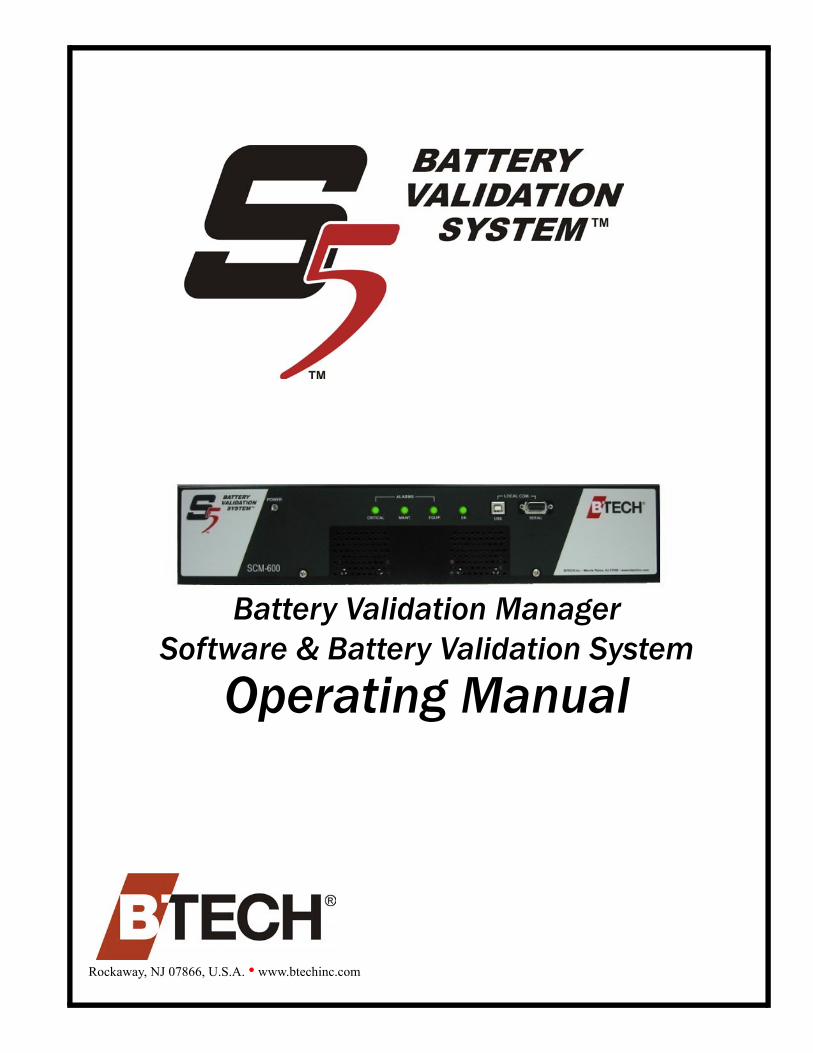
Battery Validation ManagerSoftware & Battery Validation System
Operating Manual
Rockaway, NJ 07866, U.S.A. • www.btechinc.com
2 S5 Battery Validation System
BTECH Inc. takes pride in the quality of its new documentation. However, technical inaccuracies, typographical errors and editorial omissions do occur from time to time. Although the documentation is provided “as is,” and BTECH Inc. disclaims all direct, indirect or consequential damages that may result from such errors, please let BTECH Inc. know immediately if you discover inaccuracies, errors or omissions. Roberts Sinto will make every effort to correct the deficiencies in new editions and updates.
Copyright 2005 by BTECH Inc. 10 Astro Place Rockaway, NJ 07866
Written and designed by: PS Publications 1400 Pershing Drive Lansing, MI 48910
Printed in the United States of AmericaVersion 1.206.07.05
BTECH SERVICE AND SUPPORT
Phone: 1-973-983-1120Fax: 1-973-983-1125E-mail: [email protected] page: http://www.btechinc.com SYSTEM REQUIREMENTS
The Battery Validation Manager 4.1 requires: Hardware: * A Pentium II or better PC * 128 megabyptes of memory for Windows 2000®; 256 megabytes of memory for Windows XP®
* 100 megabytes minimum hard drive space for applications and small data files * SVGA (800x600) display or better * Dial modem for operation with multiple BVS units that include dial modems Available serial ports for each short-haul modem pair required. A network adapter attached to a TCP/IP network is necessary to use the network communications function of the software. Software: Windows 2000®, or XP®
(Windows 2000®, and Windows XP® are registered trademarks of Microsoft Corporation)
Table of Contents
Product Overview .............................................................................5
Product Warranty..............................................................................6A. Hardware Warranty.............................................................................................................. 6B. Software Warranty............................................................................................................... 6C. Entitlement During the Applicable Warranty Period ........................................................ 6
Installing the Software.....................................................................91. Install the BVM Software ..................................................................................................... 92. Activate the BVS Observer................................................................................................ 113. Installing Drivers for the USB Port on SCM-600 ............................................................. 12
Starting Up......................................................................................171. Make sure the BVS hardware is configured properly..................................................... 172. Make sure the SCM-600 is turned on and connected .................................................... 193. Add the battery file(s) included on your BVM software CD ........................................... 204. Make sure the hardware is communicating with the software ...................................... 215. Ensure that settings and readings are correct................................................................ 286. Enable remote communication......................................................................................... 39
Adding Your Batteries to the System.............................................40Creating a New Location File ................................................................................................ 40Adding New Battery Location Files to the BVM Software.................................................. 45
Installation Guide 3

4 S5 Battery Validation System
Product Overview
PRODUCT OVERVIEW
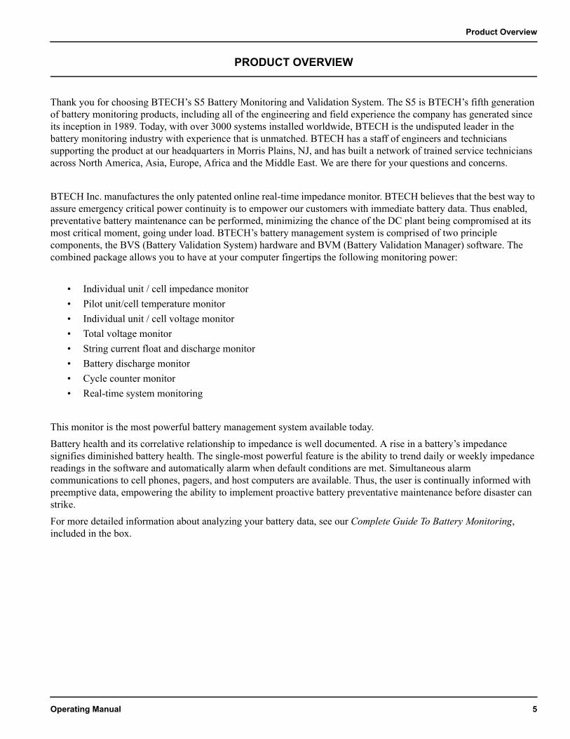
Thank you for choosing BTECH’s S5 Battery Monitoring and Validation System. The S5 is BTECH’s fifth generation of battery monitoring products, including all of the engineering and field experience the company has generated since its inception in 1989. Today, with over 3000 systems installed worldwide, BTECH is the undisputed leader in the battery monitoring industry with experience that is unmatched. BTECH has a staff of engineers and technicians supporting the product at our headquarters in Morris Plains, NJ, and has built a network of trained service technicians across North America, Asia, Europe, Africa and the Middle East. We are there for your questions and concerns.
BTECH Inc. manufactures the only patented online real-time impedance monitor. BTECH believes that the best way to assure emergency critical power continuity is to empower our customers with immediate battery data. Thus enabled, preventative battery maintenance can be performed, minimizing the chance of the DC plant being compromised at its most critical moment, going under load. BTECH’s battery management system is comprised of two principle components, the BVS (Battery Validation System) hardware and BVM (Battery Validation Manager) software. The combined package allows you to have at your computer fingertips the following monitoring power:
• Individual unit / cell impedance monitor• Pilot unit/cell temperature monitor• Individual unit / cell voltage monitor• Total voltage monitor• String current float and discharge monitor• Battery discharge monitor• Cycle counter monitor• Real-time system monitoring
This monitor is the most powerful battery management system available today.Battery health and its correlative relationship to impedance is well documented. A rise in a battery’s impedance signifies diminished battery health. The single-most powerful feature is the ability to trend daily or weekly impedance readings in the software and automatically alarm when default conditions are met. Simultaneous alarm communications to cell phones, pagers, and host computers are available. Thus, the user is continually informed with preemptive data, empowering the ability to implement proactive battery preventative maintenance before disaster can strike.For more detailed information about analyzing your battery data, see our Complete Guide To Battery Monitoring, included in the box.
Operating Manual 5
PRODUCT WARRANTY
NOTE: THIS WARRANTY IS GIVEN TO THE ORIGINAL PURCHASING END USER AND IS APPLICABLE ONLY TO PRODUCTS AND LICENSED MATERIALS SOLD OR DISTRIBUTED TO SUCH END USER BY AN AUTHORIZED BTECH RESELLER, OR BTECH INC. AND BEARING THE “BTECH” BRAND NAME.
A. Hardware Warranty•BTECH warrants to the original purchasing End User that each unit of BTECH hardware products (“Hardware
Products” or “Products”) will be free from defects in material and workmanship for a period of one (1) year from the date of shipment to End User.
•Breach of warranty will be enforceable against BTECH only if written notice of such breach is received by BTECH within the applicable warranty period.
•If a warranty claim is invalid for any reason, the End User will be charged for services performed and expenses incurred by BTECH in repairing, handling and shipping the returned Product.
•Expendable parts, such as fuses and other parts that are regularly replaced due to normal use, are excluded from this warranty.
•As to Products repaired or replaced during the original warranty period for such Product, the warranty period on the replacement Product or the repaired Product shall terminate thirty (30) days after shipment to End User or upon the termination of the original warranty period, whichever is longer.
•As to any out-of-warranty Products repaired, modified or replaced by BTECH at BTECH regular charges, the warranty period with respect to the material and workmanship hereunder shall expire thirty (30) days after the date of shipment of said Product to End User.
B. Software WarrantyThe only warranty BTECH makes to End User in connection with BTECH licensed materials, which includes BTECH software, together with related documentation and the media embodying the software (“Licensed Materials”), is that the media upon which the Licensed Materials are recorded will be replaced without charge, if BTECH in good faith determines that the media was defective and not subject to misuse for a period of ninety (90) days from the date of shipment to End User. Within thirty (30) days of determination of same, BTECH shall use commercially reasonable efforts to replace any defective media that BTECH has determined to be under warranty.
C. Entitlement During the Applicable Warranty Period
Telephone SupportTechnical telephone support shall be provided by BTECH Factory Technical Service Assistance Center to End User from 8:00 a.m. to 5:00 p.m. EST Monday through Friday, excluding holidays. Telephone support provided hereunder will be limited to that necessary to confirm functional operation or determine if a Product is performing in accordance with Section A or B above, whichever applies. Should further support be required, normal support charges will apply.
Firmware/Software for the Version LicensedShould BTECH Factory Service determine, during the course of providing support hereunder, that the End User may benefit from the installation of a firmware patch, upgrade or software bug fix, if and when BTECH, at its sole discretion, develops and releases said firmware patch, or upgrade, or software bug fix, BTECH may make it available to the End User at no charge.
6 S5 Battery Validation System

Product Warranty
Product ReplacementDuring the (a) initial thirty (30) days from the date of shipment of Hardware Products having a one (1) year warranty hereunder, such Hardware Products which, after reasonable dinguses and support attempts by BTECH Factory Service, is determined by BTECH Factory Service to be non-functioning, shall be replaced on a commercially reasonable efforts basis. BTECH and End User shall follow the procedures outlined in Section C herein for the return and replacement of such Hardware Products during the above referenced periods that End User has purchased directly from BTECH. For such Hardware Products that End User has purchased from a BTECH Reseller, the following procedures shall be followed for the return and replacement of such Hardware Products during the above referenced periods:a. BTECH must be notified by End User prior to the return of said Product. Within ten (10) days of the date of said
notification BTECH will provide End User with a valid Return Material Authorization Number (RMA).b. Within ten (10) days of receipt of a Return Material Authorization Number from BTECH, the End User shall notify
the Reseller from whom the Product was purchased of the RMA Number, request Product replacement, and obtain information regarding the location to which the End User must return the Product claimed to be defective, as well as any other pertinent information. Transportation costs relating to the delivery of warranty claims to Reseller will be borne by the End User. In no event will Reseller accept any returned Product that does not have a valid RMA Number. All Products returned to Reseller must be packaged in packing materials that affords the same degree of protection from damage and electrical discharge as the original packaging materials. All Products returned to Reseller should be configured as originally shipped to End User by removing all add-on hardware. Add-on hardware returned with the Products may be lost in the repair process, and Reseller shall bear no responsibility for such loss.
c. End User shall promptly, but in no event later than ten (10) days of receipt of an RMA Number from BTECH, deliver said shipment to a carrier at End User’s facilities as aforesaid.
d. Within thirty (30) days of receipt of same, Reseller shall use commercially reasonable efforts to replace any defective Products that BTECH or Reseller has determined to be under warranty.
e. Transportation costs relating to the return of warranty claims to the End User will be borne by Reseller only in cases where replacement is made and authorized pursuant hereto, but any applicable duties or taxes will be paid by End User. If no warranty replacement was required, all transportation costs will be borne by End User. “Emergency” transportation costs shall be borne by End User.
Return and Repaira. During the remainder of the hardware warranty period, if Products under warranty are claimed to be defective,
BTECH must be notified by End User prior to the return of said Product. Within ten (10) days of the date of said notification BTECH will provide End User with a valid Return Material Authorization number and the location to which End User must return the Product claimed to be defective. Transportation costs relating to the delivery of warranty claims to BTECH will be borne by the End User. In no event will BTECH accept any returned Product which does not have a valid Return Material Authorization number. All Products returned to BTECH should be configured as originally shipped to End User by removing all add-on hardware. Any add-on hardware returned with the Products may be lost in the repair process, and BTECH shall bear no responsibility for such loss.
b. Within the (10) days of receipt of notice from BTECH requiring return, End User shall deliver said shipment to a carrier at End User’s facilities as aforesaid.
c. Within thirty (30) days of receipt of same, BTECH shall use commercially reasonable efforts to fix or replace, at its option (except as provided in Section C herein), any defective Products that BTECH has determined to be under warranty.
d. Transportation costs relating to the return of warranty claims to the End User will be borne by BTECH only in cases where repair or replacement is made and authorized pursuant hereto, but any applicable duties or taxes will be paid by End User. If no warranty repair or replacement was required, all transportation costs will be borne by End User. “Emergency” transportation costs shall be borne by End User.
Operating Manual 7

GeneralThe warranties set forth in Sections A and B above, and the entitlements set forth in Section C above, are for the benefit of and shall apply only to End User.BTECH warranties shall not apply to any Product or Licensed Material which has been damaged as a result of, or subjected to, accident, neglect, misuse, abuse, vandalism, riot, war, acts of terrorism, negligence in transportation or handling, failure or surges in electric power, air conditioning, humidity control, flood, water, fire or smoke and heat damage, causes other than ordinary use, acts of God or causes beyond BTECH control, or if the Product or Licensed Material was not properly maintained by End User during the warranty period.There shall be no warranty or liability for any Products or Licensed Materials that have been modified by End User without BTECH prior written approval.Replacement Products or Licensed Materials outside the scope of this warranty or with respect to Product(s) or Licensed Materials out-of-warranty will be furnished at the established charges of BTECH then in effect.End User shall ensure that BTECH will have full and free access to the Products and Licensed Materials and End User’s site, if required.BTECH shall not be responsible for failure to repair or replace Products or Licensed Materials due to causes beyond its control. BTECH shall not be required to replace any Product or Licensed Material if it would be impractical for BTECH personnel to do so because of unauthorized alterations to the Products or Licensed Materials or its unauthorized connection by mechanical or electrical means to another system or device.
Limitation of LiabilityTHESE WARRANTIES AND BTECH AND ITS AFFILIATES’ LIABILITY AND END USER’S REMEDIES WITH RESPECT THERETO, AS SET FORTH HEREIN, ARE EXCLUSIVE AND EXPRESSLY IN LIEU OF ALL OTHER WARRANTIES, LIABILITIES, REMEDIES, EXPRESS OR IMPLIED, INCLUDING ANY OBLIGATION, LIABILITY, RIGHT, CLAIM OR REMEDY IN TORT, WHETHER OR NOT ARISING FROM NEGLIGENCE OF BTECH OR ITS AFFILIATES, ACTUAL OR IMPUTED, AND NO WARRANTIES, EXPRESS OR IMPLIED REPRESENTATIONS, PROMISES OR STATEMENTS HAVE BEEN MADE BY BTECH OR ITS AFFILIATES UNLESS CONTAINED IN THIS AGREEMENT. NO WARRANTY, EXPRESS OR IMPLIED, IS MADE HEREIN THAT THE LICENSED MATERIALS, PRODUCTS OR ANY PARTS ARE MERCHATABLE, OR FIT OR SUITABLE FOR THE PARTICULAR PURPOSES FOR WHICH THE LICENSED MATERIALS, PRODUCTS OR PARTS MAY BE ACQUIRED BY END USER. IN NO EVENT SHALL BTECH OR ITS AFFILIATES BE LIABLE TO END USER FOR ANY INDIRECT, INCIDENTAL, OR CONSEQUENTIAL DAMAGES INCLUDING WITHOUT LIMITATION, LOSS OF DATA, OR PROFITS, WHETHER CLAIMED BY REASON OF BREACH OF WARRANTY OR OTHERWISE, AND WITHOUT REGARD TO THE FORM OF ACTION IN WHICH SUCH CLAIM IS MADE.The Products and Licensed Materials are not specifically developed, or licensed for use in any nuclear, aviation, mass transit, or medical applications or in any other inherently dangerous applications.End User agrees to indemnify and hold BTECH harmless from any claims for losses, costs, damages, or liability arising out of or in connection with the use of the Products and/or Licensed Materials in such applications.Notwithstanding anything contained herein to the contrary, the total maximum liability of BTECH and its Affiliates under this warranty for the affected Product(s) and Licensed Materials is limited, at the option of BTECH, to either:a. BTECH use of reasonable efforts to repair any Product or Licensed Materials; orb. BTECH use of reasonable efforts to replace any Product or Licensed Materials, or any shipment as to which any
defect is claimed by End User and duly verified by BTECH; ofc. The refund of the purchase price or license fee paid.
8 S5 Battery Validation System
Installing the Software
INSTALLING THE SOFTWARE
1. Install the BVM Software
1. Install the BVM Software ........................................92. Activate the BVS Observer ..................................11
3. Installing Drivers for USB Port on SCM-600.......12
Action How to do it Picture
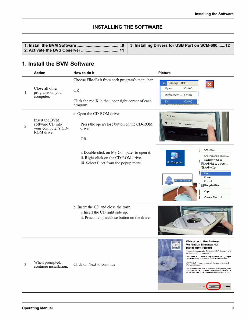
1Close all other programs on your computer.
Choose File>Exit from each program’s menu bar.
OR
Click the red X in the upper right corner of each program.
2Insert the BVM software CD into your computer’s CD-ROM drive.
a. Open the CD-ROM drive:
Press the open/close button on the CD-ROM drive.
OR
i. Double-click on My Computer to open it.ii. Right-click on the CD-ROM drive.iii. Select Eject from the popup menu.
b. Insert the CD and close the tray:i. Insert the CD right side up.ii. Press the open/close button on the drive.
3 When prompted, continue installation. Click on Next to continue.
Operating Manual 9
Action How to do it Picture
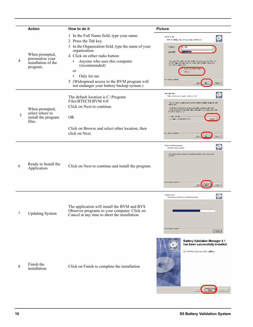
4When prompted, personalize your installation of the program.
1 In the Full Name field, type your name. 2 Press the Tab key.3 In the Organization field, type the name of your
organization.4 Click on either radio button:
• Anyone who uses this computer (recommended)
or• Only for me
5 (Widespread access to the BVM program will not endanger your battery backup system.)
5When prompted, select where to install the program files.
The default location is C:\Program Files\BTECH\BVM 4.0\Click on Next to continue.
OR
Click on Browse and select other location, then click on Next.
6 Ready to Install the Application Click on Next to continue and install the program.
7 Updating System
The application will install the BVM and BVS Observer programs to your computer. Click on Cancel at any time to abort the installation.
8 Finish the installation Click on Finish to complete the installation
10 S5 Battery Validation System
Installing the Software
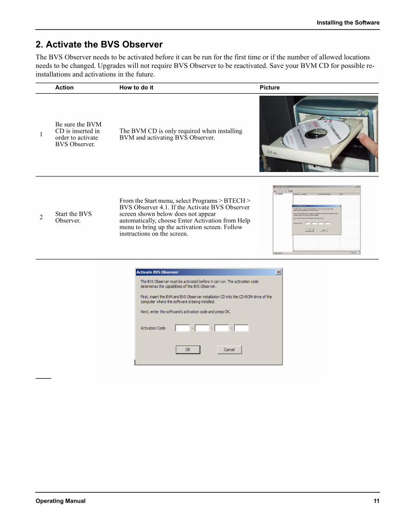
2. Activate the BVS ObserverThe BVS Observer needs to be activated before it can be run for the first time or if the number of allowed locations needs to be changed. Upgrades will not require BVS Observer to be reactivated. Save your BVM CD for possible re-installations and activations in the future.
Action How to do it Picture
1Be sure the BVM CD is inserted in order to activate BVS Observer.
The BVM CD is only required when installing BVM and activating BVS Observer.
2 Start the BVS Observer.
From the Start menu, select Programs > BTECH > BVS Observer 4.1. If the Activate BVS Observer screen shown below does not appear automatically, choose Enter Activation from Help menu to bring up the activation screen. Follow instructions on the screen.
Operating Manual 11
3. Installing Drivers for the USB Port on SCM-600.
Steps to Install USB Drivers Screen Shot
For WINDOWS XP Installation from CD
1
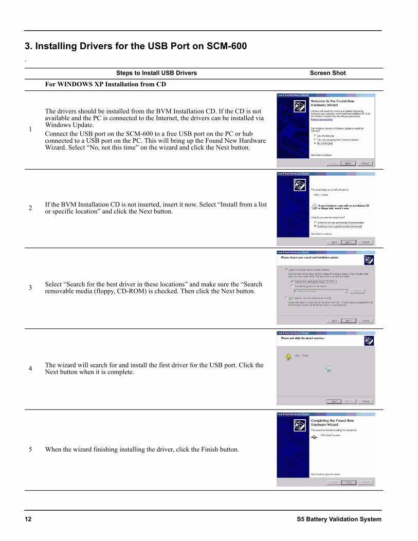
The drivers should be installed from the BVM Installation CD. If the CD is not available and the PC is connected to the Internet, the drivers can be installed via Windows Update.Connect the USB port on the SCM-600 to a free USB port on the PC or hub connected to a USB port on the PC. This will bring up the Found New Hardware Wizard. Select “No, not this time” on the wizard and click the Next button.
2 If the BVM Installation CD is not inserted, insert it now. Select “Install from a list or specific location” and click the Next button.
3 Select “Search for the best driver in these locations” and make sure the “Search removable media (floppy, CD-ROM) is checked. Then click the Next button.
4 The wizard will search for and install the first driver for the USB port. Click the Next button when it is complete.
5 When the wizard finishing installing the driver, click the Finish button.
12 S5 Battery Validation System
Installing the Software
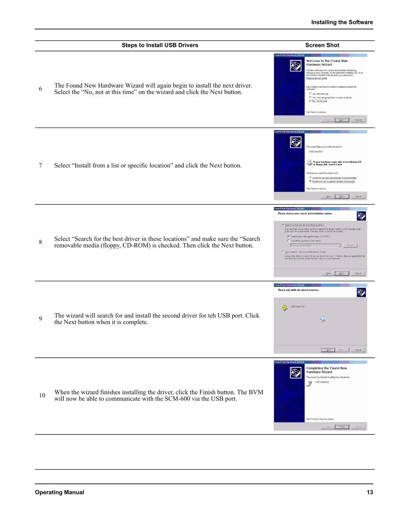
6 The Found New Hardware Wizard will again begin to install the next driver. Select the “No, not at this time” on the wizard and click the Next button.
7 Select “Install from a list or specific location” and click the Next button.
8 Select “Search for the best driver in these locations” and make sure the “Search removable media (floppy, CD-ROM) is checked. Then click the Next button.
9 The wizard will search for and install the second driver for teh USB port. Click the Next button when it is complete.
10 When the wizard finishes installing the driver, click the Finish button. The BVM will now be able to communicate with the SCM-600 via the USB port.
Steps to Install USB Drivers Screen Shot
Operating Manual 13
For WINDOWS 2000 Installation from CD Screen Shot
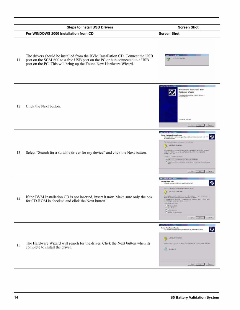
11The drivers should be installed from the BVM Installation CD. Connect the USB port on the SCM-600 to a free USB port on the PC or hub connected to a USB port on the PC. This will bring up the Found New Hardware Wizard.
12 Click the Next button.
13 Select “Search for a suitable driver for my device” and click the Next button.
14 If the BVM Installation CD is not inserted, insert it now. Make sure only the box for CD-ROM is checked and click the Next button.
15 The Hardware Wizard will search for the driver. Click the Next button when its complete to install the driver.
Steps to Install USB Drivers Screen Shot
14 S5 Battery Validation System
Installing the Software
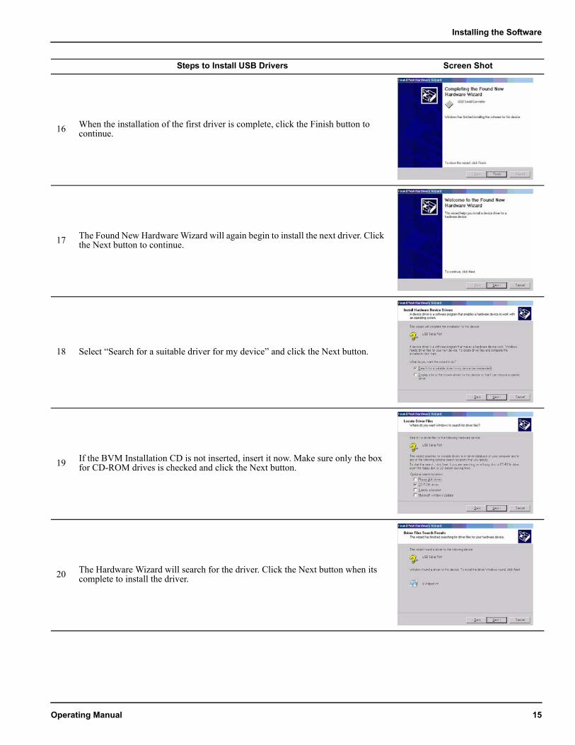
16 When the installation of the first driver is complete, click the Finish button to continue.
17 The Found New Hardware Wizard will again begin to install the next driver. Click the Next button to continue.
18 Select “Search for a suitable driver for my device” and click the Next button.
19 If the BVM Installation CD is not inserted, insert it now. Make sure only the box for CD-ROM drives is checked and click the Next button.
20 The Hardware Wizard will search for the driver. Click the Next button when its complete to install the driver.
Steps to Install USB Drivers Screen Shot
Operating Manual 15

21 When the wizard finishes installing the driver, click the Finish button. The BVM will now be able to communicate with the SCM-600 via the USB port.
Steps to Install USB Drivers Screen Shot
16 S5 Battery Validation System
Starting Up
STARTING UP
In this manual, the word “battery” refers not to a single cell but to an entire backup system for an uninterruptable power supply. In the BVM software, these battery systems are represented by *.bvm files, which contain the data which is gathered the S5 SCM-600 controller and transmitted to your computer through cables or wires (serial, USB, phone, or Ethernet).
1. Make sure the BVS hardware is configured properly
1. Make sure the BVS hardware is configured properly..................................................................17
2. Make sure the SCM-600 is turned on and connected ..............................................................19
3. Add the battery file(s) included on your BVM software CD ...........................................................20
4. Make sure the hardware is communicating with the software .................................................................21
5. Ensure that settings and readings are correct ..286. Enable remote communication............................39
Action How to do it Picture
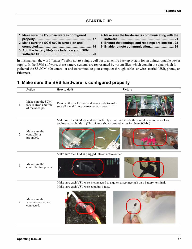
1Make sure the SCM-600 is clean and free of metal chips.
Remove the back cover and look inside to make sure all metal filings were cleared away.
2Make sure the controller is grounded.
Make sure the SCM ground wire is firmly connected inside the module and to the rack or enclosure that holds it. (This picture shows ground wires for three SCMs.)
3 Make sure the controller has power.
Make sure the SCM is plugged into an active outlet.
4Make sure the voltage sensors are connected.
Make sure each VSL wire is connected to a quick disconnect tab on a battery terminal.Make sure each VSL wire contains a fuse.
Operating Manual 17
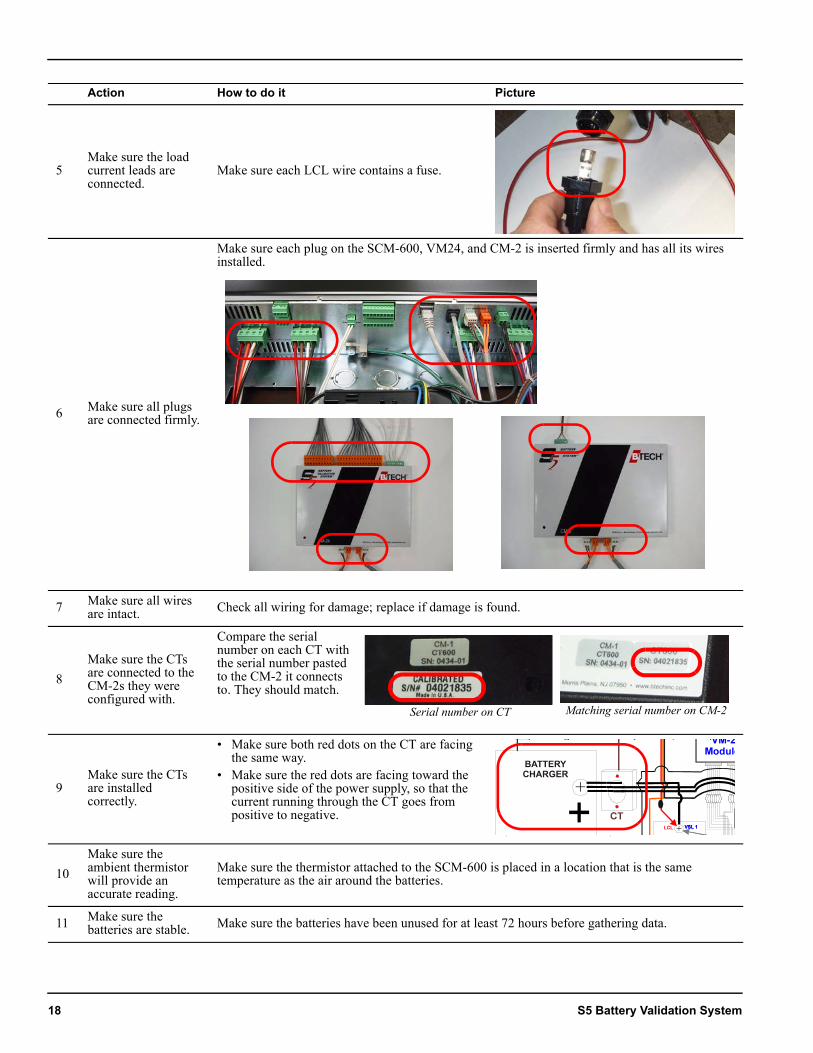
5Make sure the load current leads are connected.
Make sure each LCL wire contains a fuse.
6 Make sure all plugs are connected firmly.
Make sure each plug on the SCM-600, VM24, and CM-2 is inserted firmly and has all its wires installed.
7 Make sure all wires are intact. Check all wiring for damage; replace if damage is found.
8Make sure the CTs are connected to the CM-2s they were configured with.
Compare the serial number on each CT with the serial number pasted to the CM-2 it connects to. They should match.
9Make sure the CTs are installed correctly.
• Make sure both red dots on the CT are facing the same way.
• Make sure the red dots are facing toward the positive side of the power supply, so that the current running through the CT goes from positive to negative.
10Make sure the ambient thermistor will provide an accurate reading.
Make sure the thermistor attached to the SCM-600 is placed in a location that is the same temperature as the air around the batteries.
11 Make sure the batteries are stable. Make sure the batteries have been unused for at least 72 hours before gathering data.
Action How to do it Picture
Serial number on CT Matching serial number on CM-2
18 S5 Battery Validation System
Starting Up
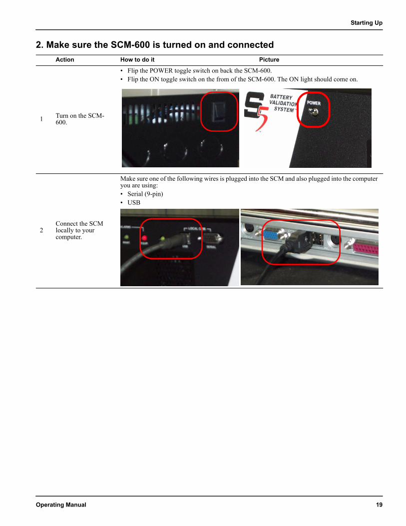
2. Make sure the SCM-600 is turned on and connected Action How to do it Picture
1 Turn on the SCM-600.
• Flip the POWER toggle switch on back the SCM-600. • Flip the ON toggle switch on the from of the SCM-600. The ON light should come on.
2Connect the SCM locally to your computer.
Make sure one of the following wires is plugged into the SCM and also plugged into the computer you are using:• Serial (9-pin)• USB
Operating Manual 19
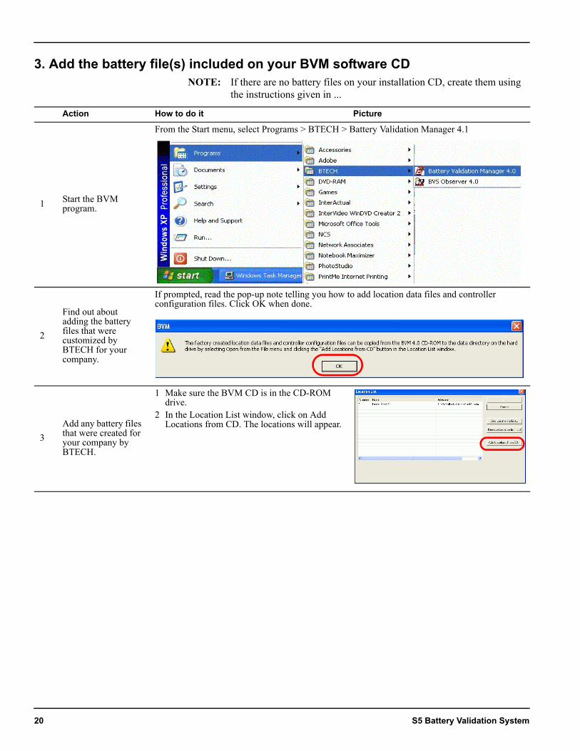
3. Add the battery file(s) included on your BVM software CDNOTE: If there are no battery files on your installation CD, create them using
the instructions given in ...
Action How to do it Picture
1 Start the BVM program.
From the Start menu, select Programs > BTECH > Battery Validation Manager 4.1
2
Find out about adding the battery files that were customized by BTECH for your company.
If prompted, read the pop-up note telling you how to add location data files and controller configuration files. Click OK when done.
3Add any battery files that were created for your company by BTECH.
1 Make sure the BVM CD is in the CD-ROM drive.
2 In the Location List window, click on Add Locations from CD. The locations will appear.
20 S5 Battery Validation System
Starting Up
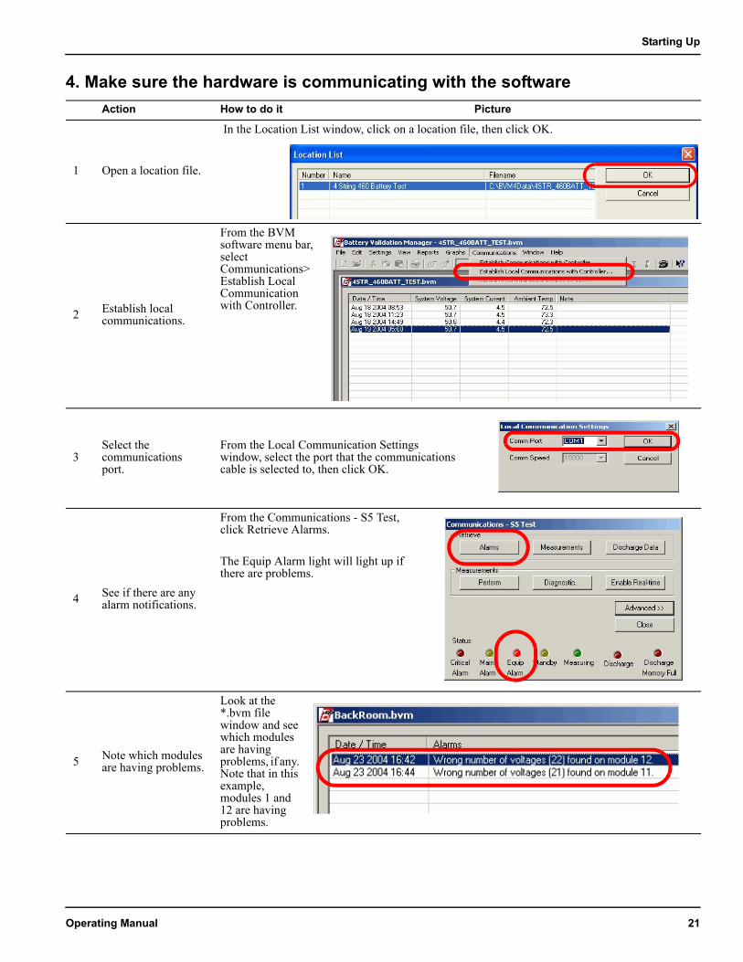
4. Make sure the hardware is communicating with the softwareAction How to do it Picture
1 Open a location file.
In the Location List window, click on a location file, then click OK.
2 Establish local communications.
From the BVM software menu bar, select Communications>Establish Local Communication with Controller.
3Select the communications port.
From the Local Communication Settings window, select the port that the communications cable is selected to, then click OK.
4 See if there are any alarm notifications.
From the Communications - S5 Test, click Retrieve Alarms.
The Equip Alarm light will light up if there are problems.
5 Note which modules are having problems.
Look at the *.bvm file window and see which modules are having problems, if any. Note that in this example, modules 1 and 12 are having problems.
Operating Manual 21
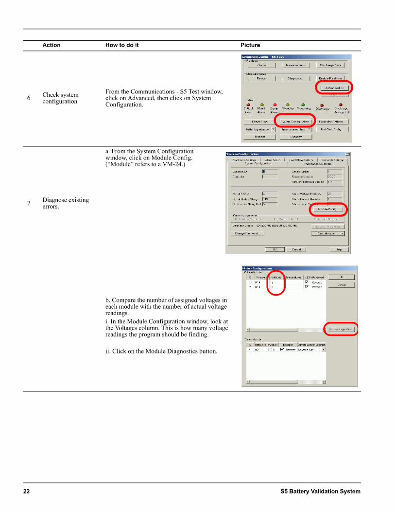
6 Check system configuration
From the Communications - S5 Test window, click on Advanced, then click on System Configuration.
7 Diagnose existing errors.
a. From the System Configuration window, click on Module Config. (“Module” refers to a VM-24.)
b. Compare the number of assigned voltages in each module with the number of actual voltage readings.i. In the Module Configuration window, look at the Voltages column. This is how many voltage readings the program should be finding.
ii. Click on the Module Diagnostics button.
Action How to do it Picture
22 S5 Battery Validation System
Starting Up
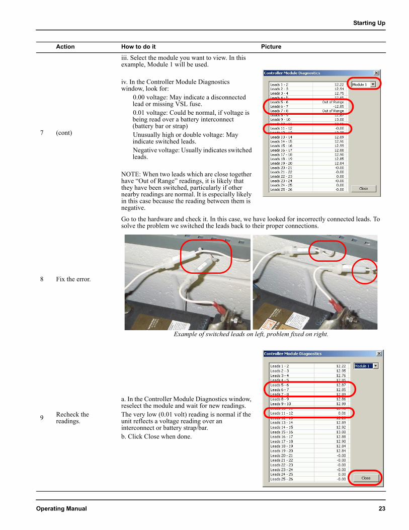
7 (cont)
iii. Select the module you want to view. In this example, Module 1 will be used.
iv. In the Controller Module Diagnostics window, look for:
0.00 voltage: May indicate a disconnected lead or missing VSL fuse.0.01 voltage: Could be normal, if voltage is being read over a battery interconnect (battery bar or strap)Unusually high or double voltage: May indicate switched leads.Negative voltage: Usually indicates switched leads.
NOTE: When two leads which are close together have “Out of Range” readings, it is likely that they have been switched, particularly if other nearby readings are normal. It is especially likely in this case because the reading between them is negative.
8 Fix the error.
Go to the hardware and check it. In this case, we have looked for incorrectly connected leads. To solve the problem we switched the leads back to their proper connections.
9 Recheck the readings.
a. In the Controller Module Diagnostics window, reselect the module and wait for new readings. The very low (0.01 volt) reading is normal if the unit reflects a voltage reading over an interconnect or battery strap/bar.b. Click Close when done.
Action How to do it Picture
Example of switched leads on left, problem fixed on right.
Operating Manual 23
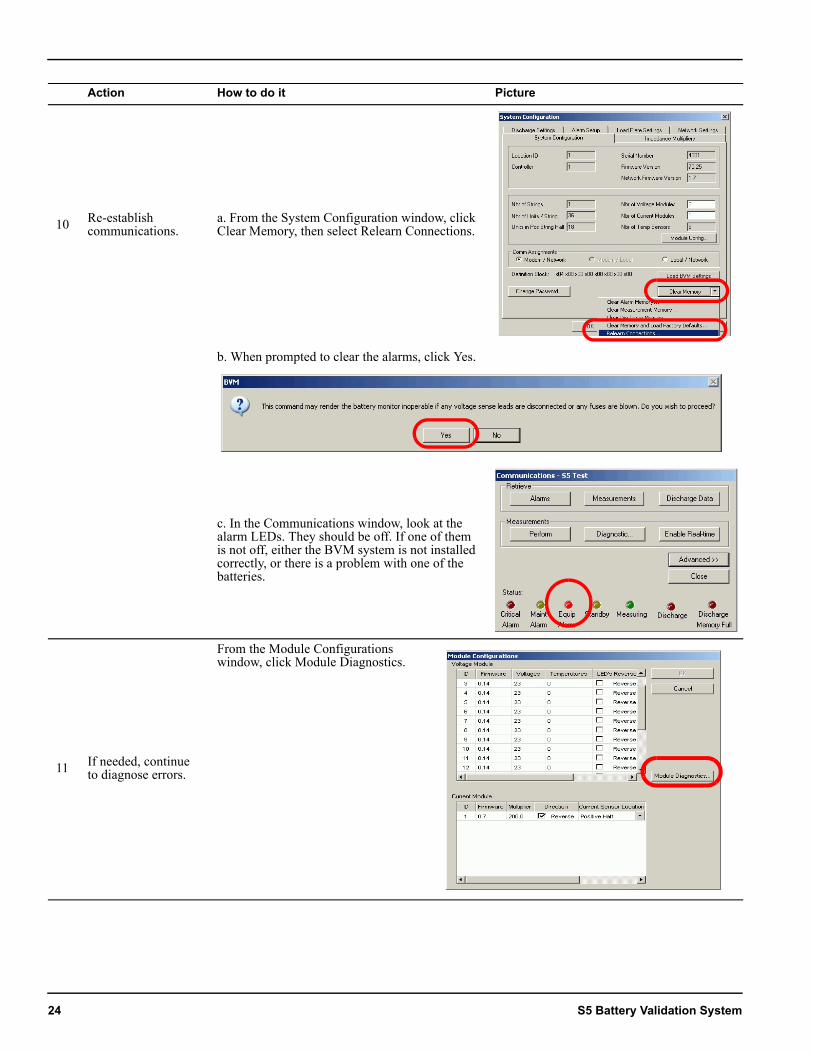
10 Re-establish communications.
a. From the System Configuration window, click Clear Memory, then select Relearn Connections.
b. When prompted to clear the alarms, click Yes.
c. In the Communications window, look at the alarm LEDs. They should be off. If one of them is not off, either the BVM system is not installed correctly, or there is a problem with one of the batteries.
11 If needed, continue to diagnose errors.
From the Module Configurations window, click Module Diagnostics.
Action How to do it Picture
24 S5 Battery Validation System
Starting Up
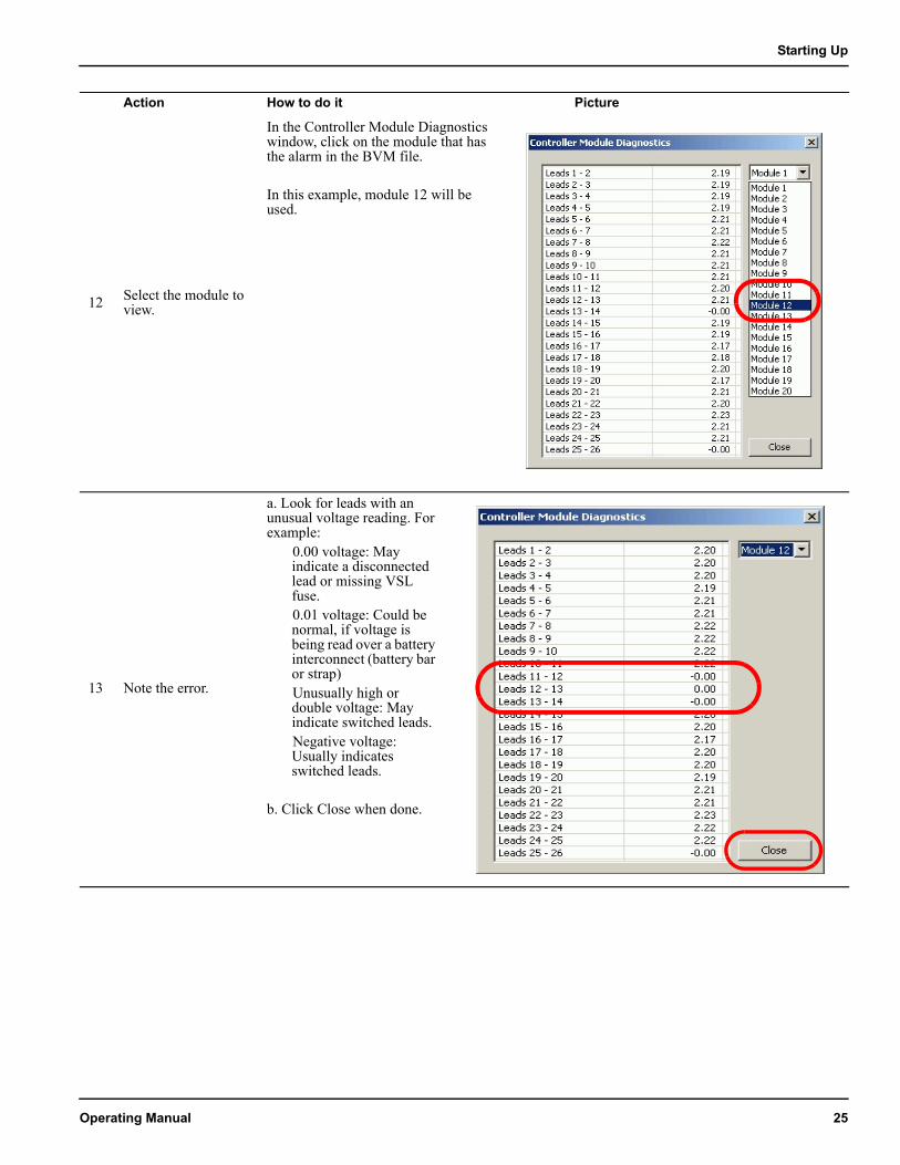
12 Select the module to view.
In the Controller Module Diagnostics window, click on the module that has the alarm in the BVM file.
In this example, module 12 will be used.
13 Note the error.
a. Look for leads with an unusual voltage reading. For example:
0.00 voltage: May indicate a disconnected lead or missing VSL fuse.0.01 voltage: Could be normal, if voltage is being read over a battery interconnect (battery bar or strap)Unusually high or double voltage: May indicate switched leads.Negative voltage: Usually indicates switched leads.
b. Click Close when done.
Action How to do it Picture
Operating Manual 25
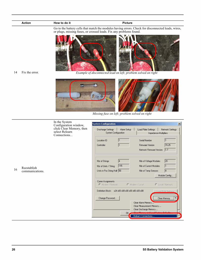
14 Fix the error.
Go to the battery cells that match the modules having errors. Check for disconnected leads, wires, or plugs, missing fuses, or crossed leads. Fix any problems found.
16 Reestablish communications.
In the System Configuration window, click Clear Memory, then select Relearn Connections...
Action How to do it Picture
Example of disconnected lead on left; problem solved on right
Missing fuse on left; problem solved on right
26 S5 Battery Validation System
Starting Up
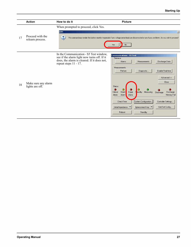
17 Proceed with the relearn process.
When prompted to proceed, click Yes.
18 Make sure any alarm lights are off.
In the Communication - S5 Test window, see if the alarm light now turns off. If it does, the alarm is cleared. If it does not, repeat steps 11 - 17.
Action How to do it Picture
Operating Manual 27
5. Ensure that settings and readings are correctAction How to do it Picture
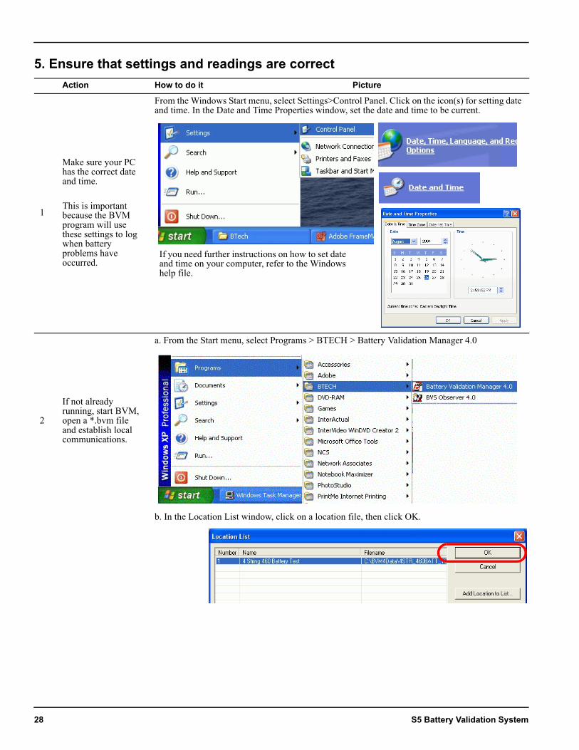
1
Make sure your PC has the correct date and time.
This is important because the BVM program will use these settings to log when battery problems have occurred.
From the Windows Start menu, select Settings>Control Panel. Click on the icon(s) for setting date and time. In the Date and Time Properties window, set the date and time to be current.
2
If not already running, start BVM, open a *.bvm file and establish local communications.
a. From the Start menu, select Programs > BTECH > Battery Validation Manager 4.0
b. In the Location List window, click on a location file, then click OK.
If you need further instructions on how to set date and time on your computer, refer to the Windows help file.
28 S5 Battery Validation System
Starting Up
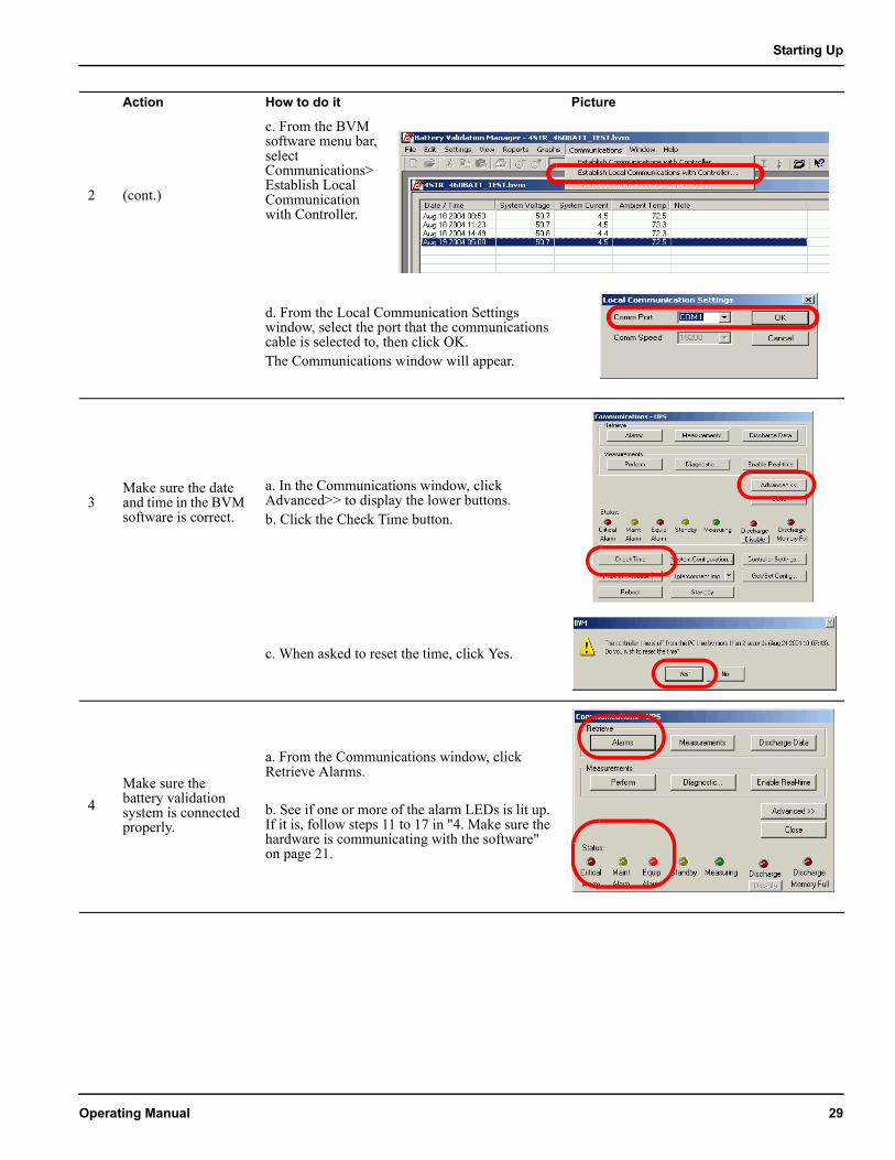
2 (cont.)
c. From the BVM software menu bar, select Communications>Establish Local Communication with Controller.
d. From the Local Communication Settings window, select the port that the communications cable is selected to, then click OK.The Communications window will appear.
3Make sure the date and time in the BVM software is correct.
a. In the Communications window, click Advanced>> to display the lower buttons.b. Click the Check Time button.
c. When asked to reset the time, click Yes.
4Make sure the battery validation system is connected properly.
a. From the Communications window, click Retrieve Alarms.
b. See if one or more of the alarm LEDs is lit up. If it is, follow steps 11 to 17 in "4. Make sure the hardware is communicating with the software" on page 21.
Action How to do it Picture
Operating Manual 29
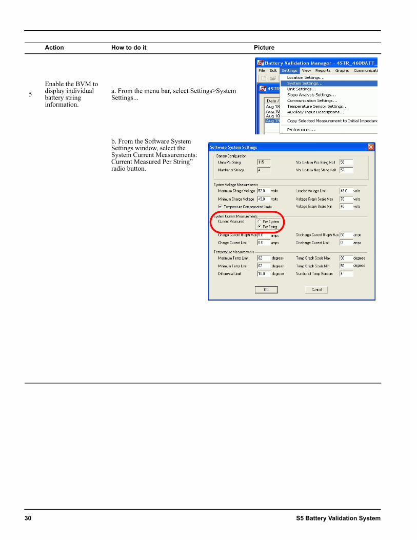
5Enable the BVM to display individual battery string information.
a. From the menu bar, select Settings>System Settings...
b. From the Software System Settings window, select the System Current Measurements: Current Measured Per String” radio button.
Action How to do it Picture
30 S5 Battery Validation System
Starting Up
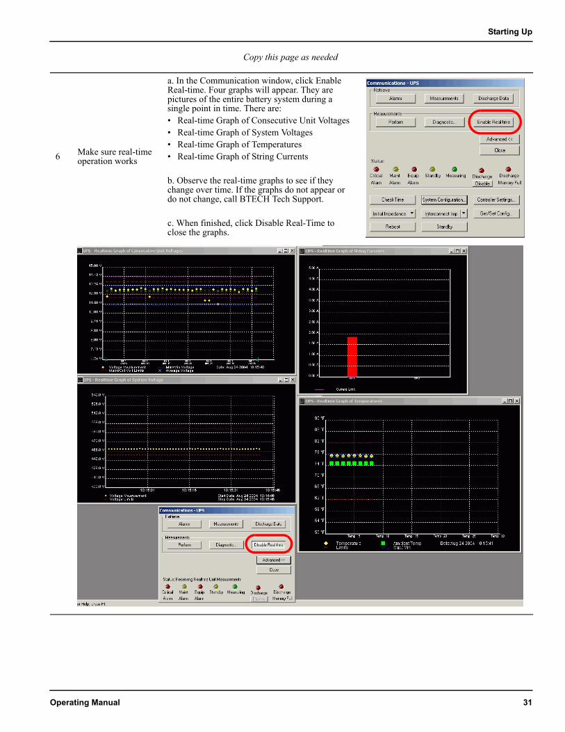
6 Make sure real-time operation works
a. In the Communication window, click Enable Real-time. Four graphs will appear. They are pictures of the entire battery system during a single point in time. There are:• Real-time Graph of Consecutive Unit Voltages• Real-time Graph of System Voltages• Real-time Graph of Temperatures• Real-time Graph of String Currents
b. Observe the real-time graphs to see if they change over time. If the graphs do not appear or do not change, call BTECH Tech Support.
c. When finished, click Disable Real-Time to close the graphs.
Action How to do it PictureCopy this page as needed
Operating Manual 31
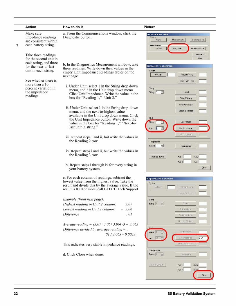
7
Make sure impedance readings are consistent within each battery string.
Take three readings for the second unit in each string, and three for the next-to-last unit in each string.
See whether there is more than a 10 percent variation in the impedance readings.
a. From the Communications window, click the Diagnostic button.
b. In the Diagnostics Measurement window, take three readings: Write down their values in the empty Unit Impedance Readings tables on the next page.
i. Under Unit, select 1 in the String drop down menu, and 2 in the Unit drop down menu. Click Unit Impedance. Write the value in the box for “Reading 1,” “Unit 2.”
ii. Under Unit, select 1 in the String drop-down menu, and the next-to-highest value available in the Unit drop down menu. Click the Unit Impedance button. Write down the value in the box for “Reading 1,” “Next-to-last unit in string.”
iii. Repeat steps i and ii, but write the values in the Reading 2 row.
iv. Repeat steps i and ii, but write the values in the Reading 3 row.
v. Repeat steps i through iv for every string in your battery system.
c. For each column of readings, subtract the lowest value from the highest value. Take the result and divide this by the average value. If the result is 0.10 or more, call BTECH Tech Support.
Example (from next page):Highest reading in Unit 2 column: 3.07Lowest reading in Unit 2 column: - 3.06Difference . 01
Average reading = (3.07+3.06+3.06) /3 = 3.063Difference divided by average reading = .
01 / 3.063 =0.0033
This indicates very stable impedance readings.
d. Click Close when done.
Action How to do it Picture
32 S5 Battery Validation System
Starting Up
Action How to do it Picture
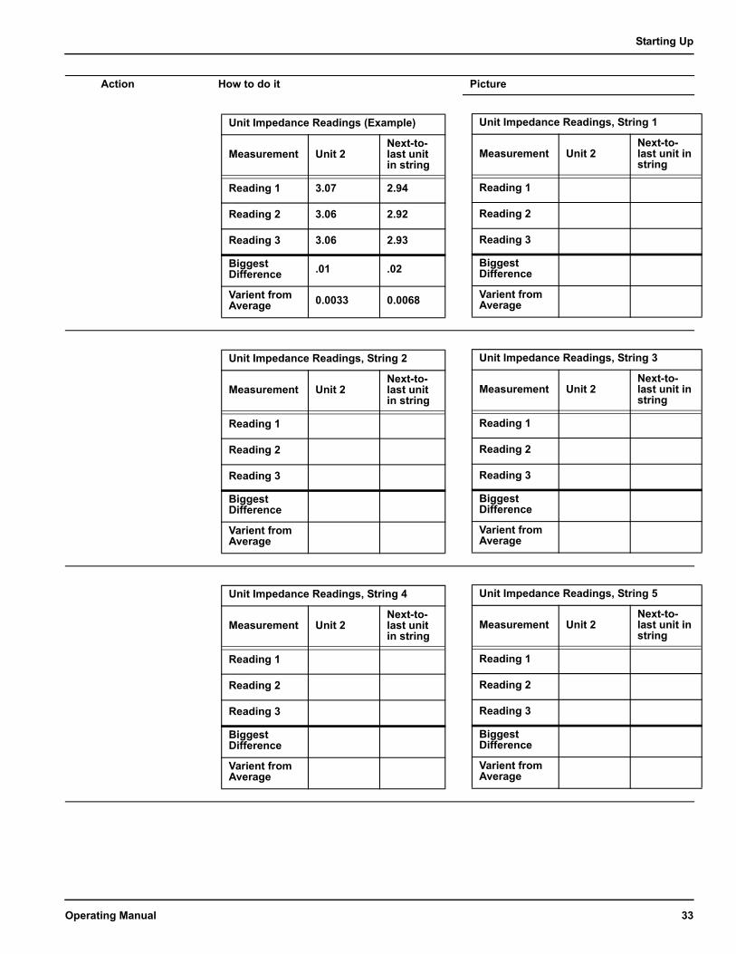
Unit Impedance Readings (Example)
Measurement Unit 2Next-to-last unit in string
Reading 1 3.07 2.94
Reading 2 3.06 2.92
Reading 3 3.06 2.93
Biggest Difference .01 .02
Varient from Average 0.0033 0.0068
Unit Impedance Readings, String 1
Measurement Unit 2Next-to-last unit in string
Reading 1
Reading 2
Reading 3
Biggest Difference
Varient from Average
Unit Impedance Readings, String 2
Measurement Unit 2Next-to-last unit in string
Reading 1
Reading 2
Reading 3
Biggest Difference
Varient from Average
Unit Impedance Readings, String 3
Measurement Unit 2Next-to-last unit in string
Reading 1
Reading 2
Reading 3
Biggest Difference
Varient from Average
Unit Impedance Readings, String 4
Measurement Unit 2Next-to-last unit in string
Reading 1
Reading 2
Reading 3
Biggest Difference
Varient from Average
Unit Impedance Readings, String 5
Measurement Unit 2Next-to-last unit in string
Reading 1
Reading 2
Reading 3
Biggest Difference
Varient from Average
Operating Manual 33
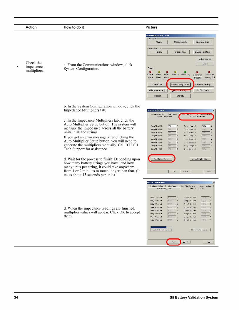
8Check the impedance multipliers.
a. From the Communications window, click System Configuration.
b. In the System Configuration window, click the Impedance Multipliers tab.
c. In the Impedance Multipliers tab, click the Auto Multiplier Setup button. The system will measure the impedance across all the battery units in all the strings. If you get an error message after clicking the Auto Multiplier Setup button, you will need to generate the multipliers manually. Call BTECH Tech Support for assistance.
d. Wait for the process to finish. Depending upon how many battery strings you have, and how many units per string, it could take anywhere from 1 or 2 minutes to much longer than that. (It takes about 15 seconds per unit.)
d. When the impedance readings are finished, multiplier values will appear. Click OK to accept them.
Action How to do it Picture
34 S5 Battery Validation System
Starting Up
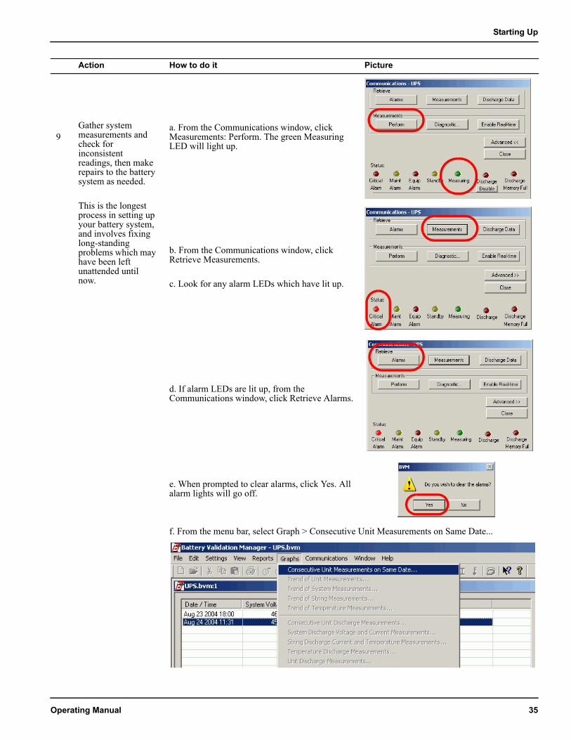
9Gather system measurements and check for inconsistent readings, then make repairs to the battery system as needed.
This is the longest process in setting up your battery system, and involves fixing long-standing problems which may have been left unattended until now.
a. From the Communications window, click Measurements: Perform. The green Measuring LED will light up.
b. From the Communications window, click Retrieve Measurements.
c. Look for any alarm LEDs which have lit up.
d. If alarm LEDs are lit up, from the Communications window, click Retrieve Alarms.
e. When prompted to clear alarms, click Yes. All alarm lights will go off.
f. From the menu bar, select Graph > Consecutive Unit Measurements on Same Date...
Action How to do it Picture
Operating Manual 35
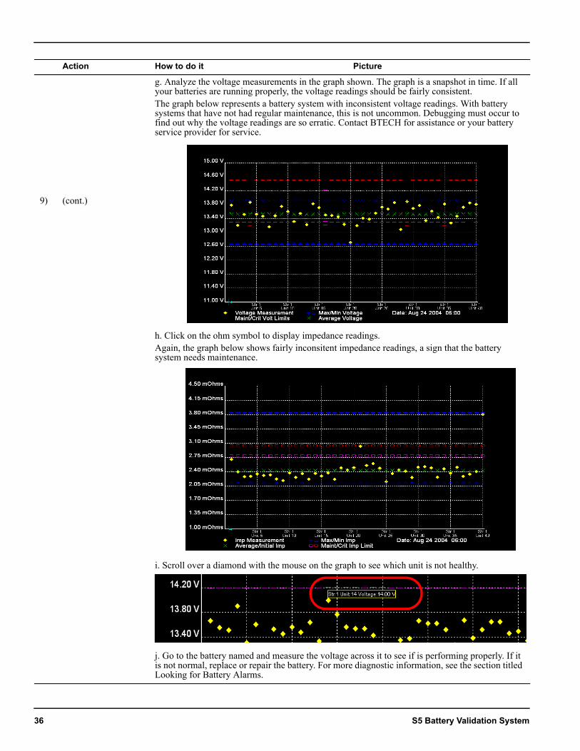
9) (cont.)
g. Analyze the voltage measurements in the graph shown. The graph is a snapshot in time. If all your batteries are running properly, the voltage readings should be fairly consistent.The graph below represents a battery system with inconsistent voltage readings. With battery systems that have not had regular maintenance, this is not uncommon. Debugging must occur to find out why the voltage readings are so erratic. Contact BTECH for assistance or your battery service provider for service.
h. Click on the ohm symbol to display impedance readings.Again, the graph below shows fairly inconsitent impedance readings, a sign that the battery system needs maintenance.
i. Scroll over a diamond with the mouse on the graph to see which unit is not healthy.
j. Go to the battery named and measure the voltage across it to see if is performing properly. If it is not normal, replace or repair the battery. For more diagnostic information, see the section titled Looking for Battery Alarms.
Action How to do it Picture
36 S5 Battery Validation System
Starting Up
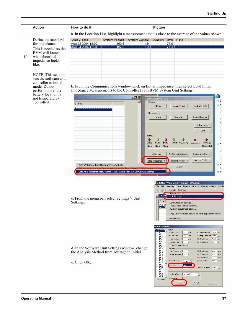
10
Define the standard for impedance. This is needed so the BVM will know what abnormal impedance looks like.
NOTE: This section sets the software and controller to initial mode. Do not perform this if the battery location is not temperature-controlled.
a. In the Location List, highlight a measurement that is close to the average of the values shown.
b. From the Communications window, click on Initial Impedance, then select Load Initial Impedance Measurements to the Controller From BVM System Unit Settings.
c. From the menu bar, select Settings > Unit Settings.
d. In the Software Unit Settings window, change the Analysis Method from Average to Initial.
e. Click OK.
Action How to do it Picture
Operating Manual 37
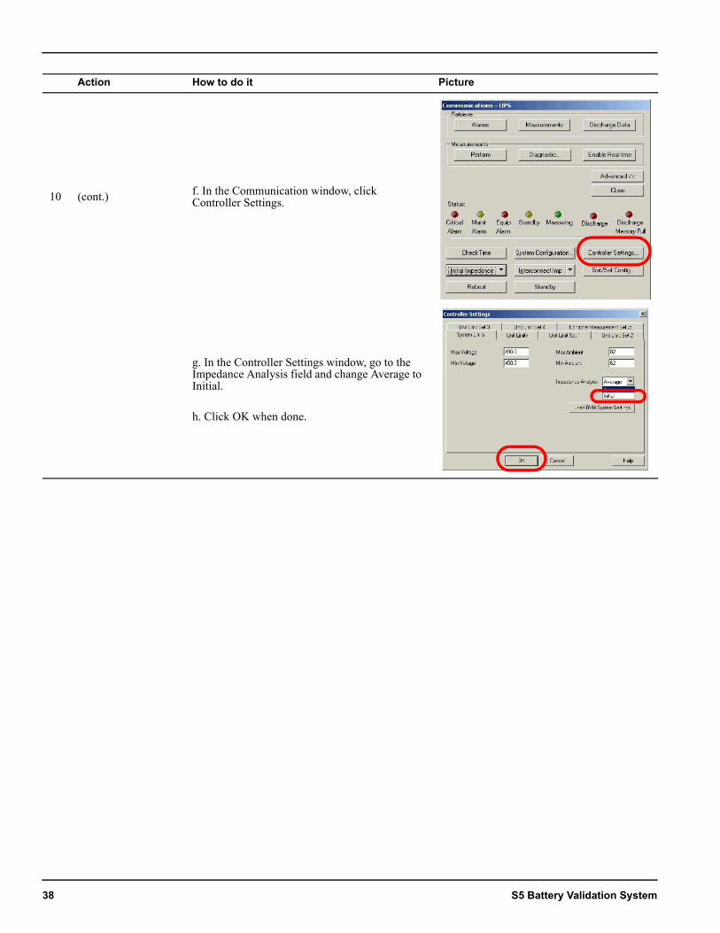
10 (cont.) f. In the Communication window, click Controller Settings.
g. In the Controller Settings window, go to the Impedance Analysis field and change Average to Initial.
h. Click OK when done.
Action How to do it Picture
38 S5 Battery Validation System
Starting Up
6. Enable remote communicationAction How to do it Picture
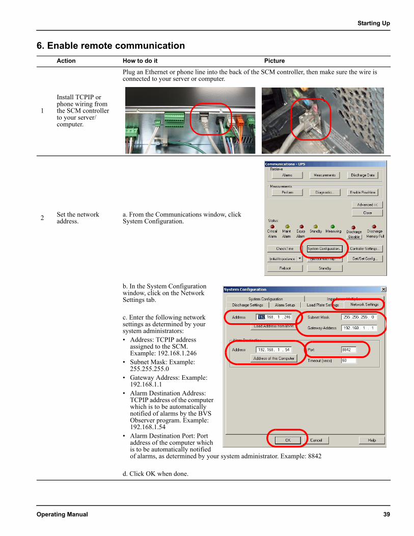
1
Install TCPIP or phone wiring from the SCM controller to your server/computer.
Plug an Ethernet or phone line into the back of the SCM controller, then make sure the wire is connected to your server or computer.
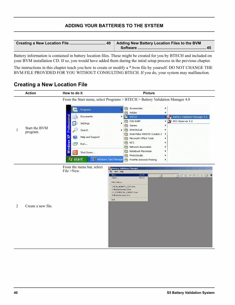
2 Set the network address.
a. From the Communications window, click System Configuration.
b. In the System Configuration window, click on the Network Settings tab.
c. Enter the following network settings as determined by your system administrators:• Address: TCPIP address
assigned to the SCM. Example: 192.168.1.246
• Subnet Mask: Example: 255.255.255.0
• Gateway Address: Example: 192.168.1.1
• Alarm Destination Address: TCPIP address of the computer which is to be automatically notified of alarms by the BVS Observer program. Example: 192.168.1.54
• Alarm Destination Port: Port address of the computer which is to be automatically notified of alarms, as determined by your system administrator. Example: 8842
d. Click OK when done.
Operating Manual 39
ADDING YOUR BATTERIES TO THE SYSTEM
Battery information is contained in battery location files. These might be created for you by BTECH and included on your BVM installation CD. If so, you would have added them during the intial setup process in the previous chapter.The instructions in this chapter teach you how to create or modify a *.bvm file by yourself. DO NOT CHANGE THE BVM FILE PROVIDED FOR YOU WITHOUT CONSULTING BTECH. If you do, your system may malfunction.
Creating a New Location File
Creating a New Location File .................................. 40 Adding New Battery Location Files to the BVM Software ................................................................ 45
Action How to do it Picture
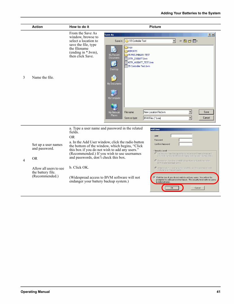
1 Start the BVM program.
From the Start menu, select Programs > BTECH > Battery Validation Manager 4.0
2 Create a new file.
From the menu bar, select File >New.
40 S5 Battery Validation System
Adding Your Batteries to the System
3 Name the file.
From the Save As window, browse to select a location to save the file, type the filename (ending in *.bvm), then click Save.
4
Set up a user names and password.
OR
Allow all users to see the battery file. (Recommended.)
a. Type a user name and password in the related fields.ORa. In the Add User window, click the radio button the bottom of the window, which begins, “Click this box if you do not wish to add any users.” (Recommended.) If you wish to use usernames and passwords, don’t check this box.
b. Click OK.
(Widespread access to BVM software will not endanger your battery backup system.)
Action How to do it Picture
Operating Manual 41
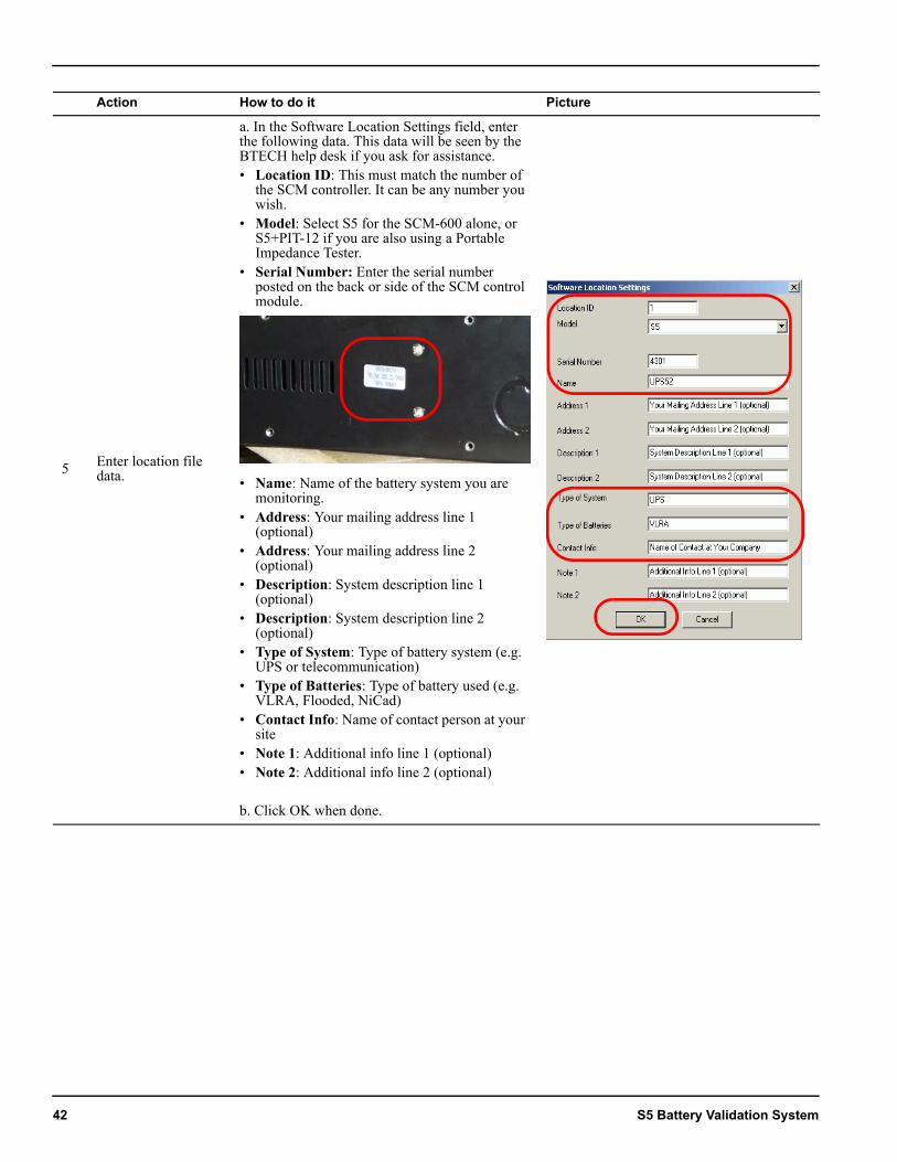
5 Enter location file data.
a. In the Software Location Settings field, enter the following data. This data will be seen by the BTECH help desk if you ask for assistance.• Location ID: This must match the number of
the SCM controller. It can be any number you wish.
• Model: Select S5 for the SCM-600 alone, or S5+PIT-12 if you are also using a Portable Impedance Tester.
• Serial Number: Enter the serial number posted on the back or side of the SCM control module.
• Name: Name of the battery system you are monitoring.
• Address: Your mailing address line 1 (optional)
• Address: Your mailing address line 2 (optional)
• Description: System description line 1 (optional)
• Description: System description line 2 (optional)
• Type of System: Type of battery system (e.g. UPS or telecommunication)
• Type of Batteries: Type of battery used (e.g. VLRA, Flooded, NiCad)
• Contact Info: Name of contact person at your site
• Note 1: Additional info line 1 (optional)• Note 2: Additional info line 2 (optional)
b. Click OK when done.
Action How to do it Picture
42 S5 Battery Validation System
Adding Your Batteries to the System
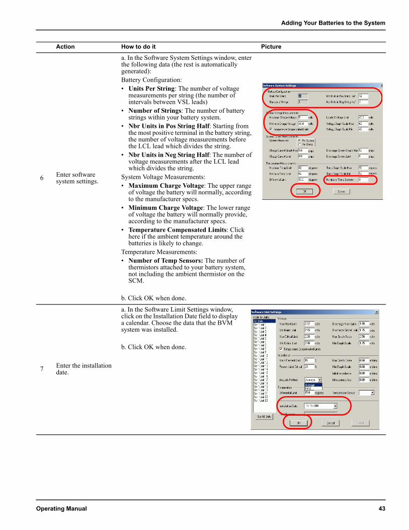
6 Enter software system settings.
a. In the Software System Settings window, enter the following data (the rest is automatically generated):Battery Configuration:• Units Per String: The number of voltage
measurements per string (the number of intervals between VSL leads)
• Number of Strings: The number of battery strings within your battery system.
• Nbr Units in Pos String Half: Starting from the most positive terminal in the battery string, the number of voltage measurements before the LCL lead which divides the string.
• Nbr Units in Neg String Half: The number of voltage measurements after the LCL lead which divides the string.
System Voltage Measurements:• Maximum Charge Voltage: The upper range
of voltage the battery will normally, according to the manufacturer specs.
• Minimum Charge Voltage: The lower range of voltage the battery will normally provide, according to the manufacturer specs.
• Temperature Compensated Limits: Click here if the ambient temperature around the batteries is likely to change.
Temperature Measurements:• Number of Temp Sensors: The number of
thermistors attached to your battery system, not including the ambient thermistor on the SCM.
b. Click OK when done.
7 Enter the installation date.
a. In the Software Limit Settings window, click on the Installation Date field to display a calendar. Choose the data that the BVM system was installed.
b. Click OK when done.
Action How to do it Picture
Operating Manual 43
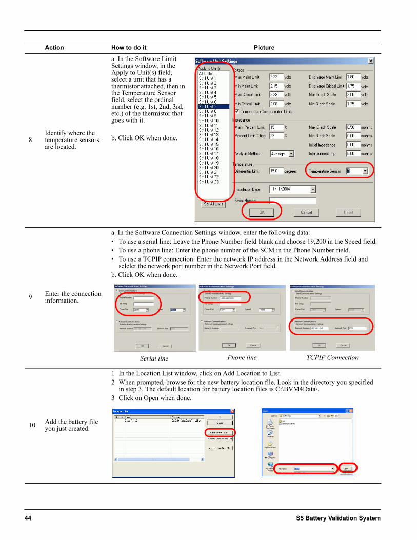
8Identify where the temperature sensors are located.
a. In the Software Limit Settings window, in the Apply to Unit(s) field, select a unit that has a thermistor attached, then in the Temperature Sensor field, select the ordinal number (e.g. 1st, 2nd, 3rd, etc.) of the thermistor that goes with it.
b. Click OK when done.
9 Enter the connection information.
a. In the Software Connection Settings window, enter the following data:• To use a serial line: Leave the Phone Number field blank and choose 19,200 in the Speed field.• To use a phone line: Enter the phone number of the SCM in the Phone Number field.• To use a TCPIP connection: Enter the network IP address in the Network Address field and
selelct the network port number in the Network Port field.b. Click OK when done.
10 Add the battery file you just created.
1 In the Location List window, click on Add Location to List.2 When prompted, browse for the new battery location file. Look in the directory you specified
in step 3. The default location for battery location files is C:\BVM4Data\.3 Click on Open when done.
Action How to do it Picture
Serial line Phone line TCPIP Connection
44 S5 Battery Validation System
Adding Your Batteries to the System
Adding New Battery Location Files to the BVM SoftwareAction How to do it Picture
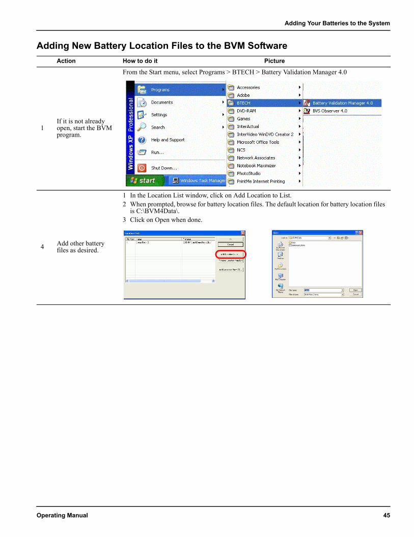
1If it is not already open, start the BVM program.
From the Start menu, select Programs > BTECH > Battery Validation Manager 4.0
4 Add other battery files as desired.
1 In the Location List window, click on Add Location to List.2 When prompted, browse for battery location files. The default location for battery location files
is C:\BVM4Data\.3 Click on Open when done.
Operating Manual 45
CHECKING BATTERIES FOR PROBLEMS
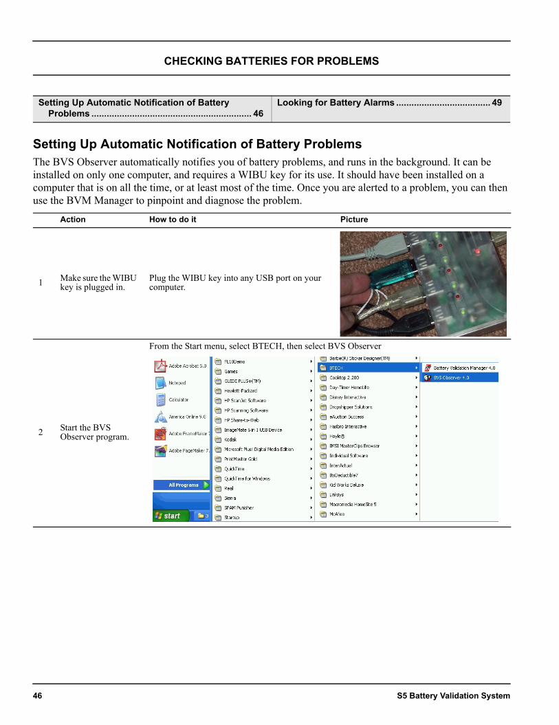
Setting Up Automatic Notification of Battery ProblemsThe BVS Observer automatically notifies you of battery problems, and runs in the background. It can be installed on only one computer, and requires a WIBU key for its use. It should have been installed on a computer that is on all the time, or at least most of the time. Once you are alerted to a problem, you can then use the BVM Manager to pinpoint and diagnose the problem.
Setting Up Automatic Notification of Battery Problems ............................................................... 46
Looking for Battery Alarms ..................................... 49
Action How to do it Picture
1 Make sure the WIBU key is plugged in.
Plug the WIBU key into any USB port on your computer.
2 Start the BVS Observer program.
From the Start menu, select BTECH, then select BVS Observer
46 S5 Battery Validation System
Checking Batteries for Problems
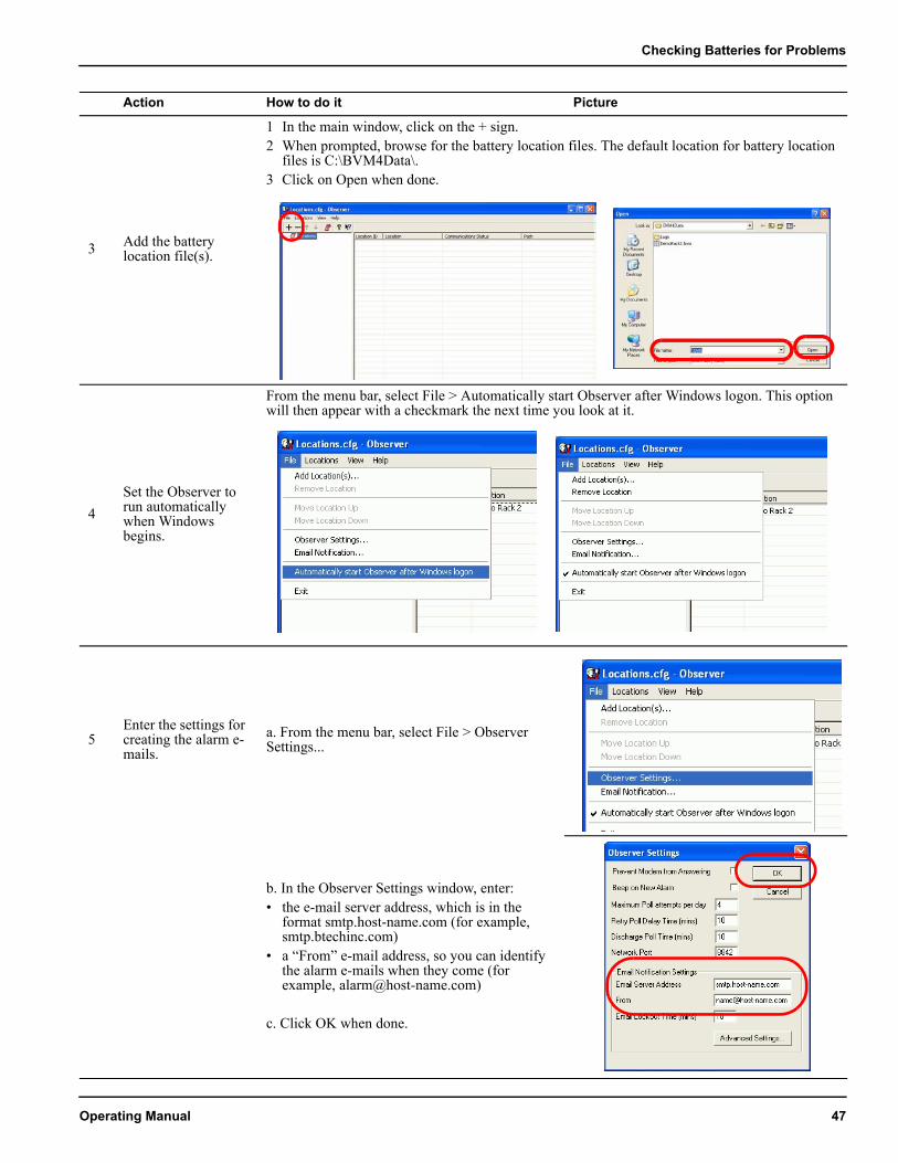
3 Add the battery location file(s).
1 In the main window, click on the + sign.2 When prompted, browse for the battery location files. The default location for battery location
files is C:\BVM4Data\.3 Click on Open when done.
4Set the Observer to run automatically when Windows begins.
From the menu bar, select File > Automatically start Observer after Windows logon. This option will then appear with a checkmark the next time you look at it.
5Enter the settings for creating the alarm e-mails.
a. From the menu bar, select File > Observer Settings...
b. In the Observer Settings window, enter: • the e-mail server address, which is in the
format smtp.host-name.com (for example, smtp.btechinc.com)
• a “From” e-mail address, so you can identify the alarm e-mails when they come (for example, [email protected])
c. Click OK when done.
Action How to do it Picture
Operating Manual 47
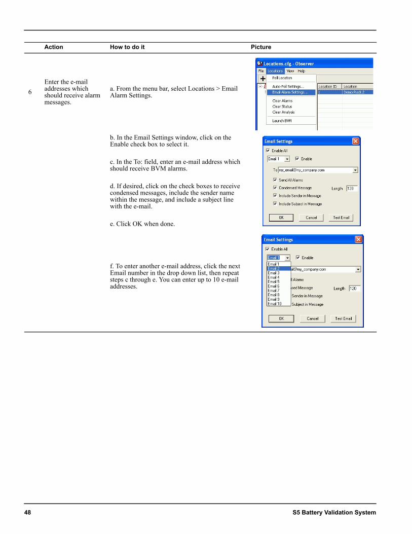
6Enter the e-mail addresses which should receive alarm messages.
a. From the menu bar, select Locations > Email Alarm Settings.
b. In the Email Settings window, click on the Enable check box to select it.
c. In the To: field, enter an e-mail address which should receive BVM alarms.
d. If desired, click on the check boxes to receive condensed messages, include the sender name within the message, and include a subject line with the e-mail.
e. Click OK when done.
f. To enter another e-mail address, click the next Email number in the drop down list, then repeat steps c through e. You can enter up to 10 e-mail addresses.
Action How to do it Picture
48 S5 Battery Validation System
Checking Batteries for Problems
Looking for Battery AlarmsAction How to do it Picture
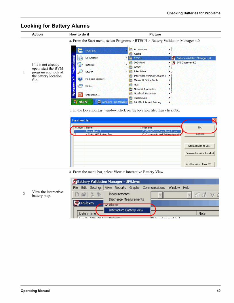
1
If it is not already open, start the BVM program and look at the battery location file.
a. From the Start menu, select Programs > BTECH > Battery Validation Manager 4.0
b. In the Location List window, click on the location file, then click OK.
2 View the interactive battery map.
a. From the menu bar, select View > Interactive Battery View.
Operating Manual 49
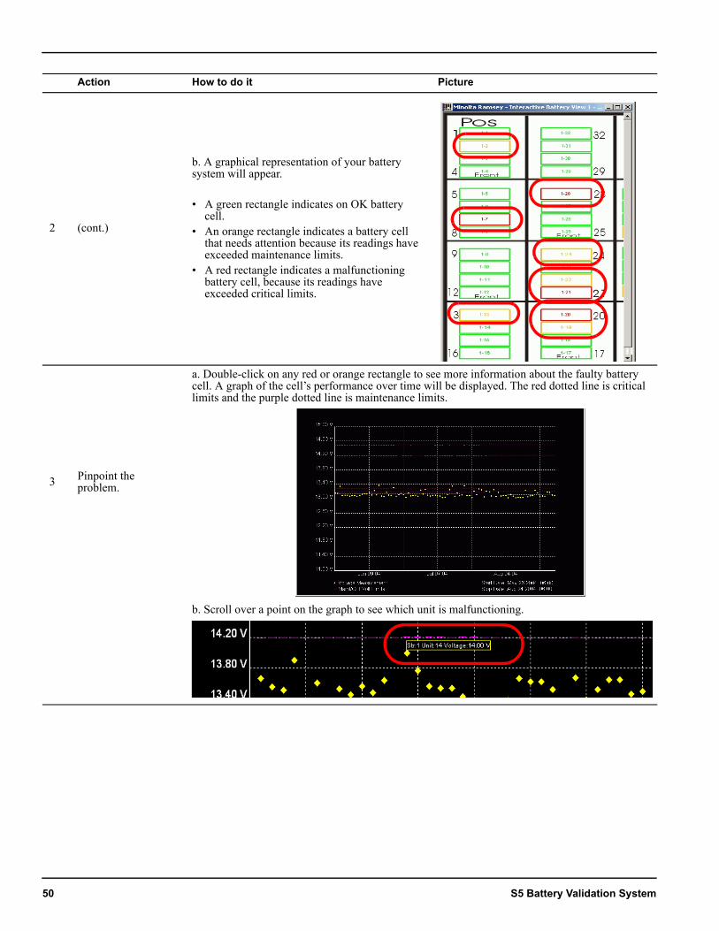
2 (cont.)
b. A graphical representation of your battery system will appear.
• A green rectangle indicates on OK battery cell.
• An orange rectangle indicates a battery cell that needs attention because its readings have exceeded maintenance limits.
• A red rectangle indicates a malfunctioning battery cell, because its readings have exceeded critical limits.
3 Pinpoint the problem.
a. Double-click on any red or orange rectangle to see more information about the faulty battery cell. A graph of the cell’s performance over time will be displayed. The red dotted line is critical limits and the purple dotted line is maintenance limits.
b. Scroll over a point on the graph to see which unit is malfunctioning.
Action How to do it Picture
50 S5 Battery Validation System
Viewing Battery Activity
VIEWING BATTERY ACTIVITY
Controlling When Battery Measurements are Taken and How They AppearBy default, measurements of battery voltage, impedance and temperature are taken once every seven days. (Measurements are also taken immediately when a battery discharges power; for example when the main power supply fails and the battery backup system takes over.) You can change the frequency of battery measurements through the Controller Settings window. By default, the scale, or Y-axis, of the battery measurement graph has been set to what is considered to be an appropriate range. However, if you want to see more detail, you can spread the range over a greater area.
Controlling When Battery Measurements are Taken and How They Appear ..........................................51
Viewing Maintenance Limits and Critical Limits....53
Viewing Battery Measurements...............................55Seeing When the Batteries Have Been Used/
Discharged ............................................................56
Action How to do it Picture
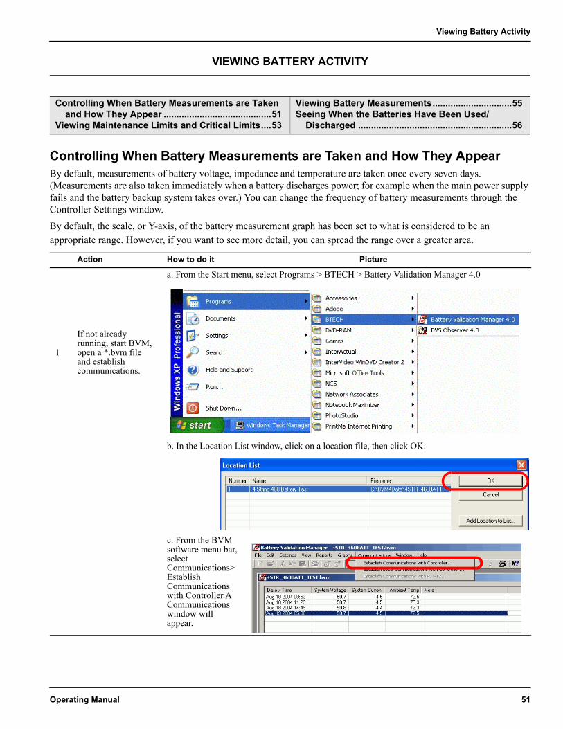
1
If not already running, start BVM, open a *.bvm file and establish communications.
a. From the Start menu, select Programs > BTECH > Battery Validation Manager 4.0
b. In the Location List window, click on a location file, then click OK.
c. From the BVM software menu bar, select Communications>Establish Communications with Controller.A Communications window will appear.
Operating Manual 51
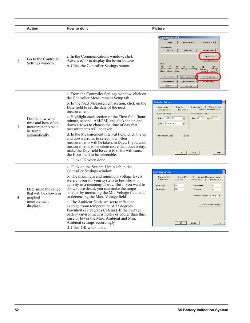
2 Go to the Controller Settings window.
a. In the Communications window, click Advanced>> to display the lower buttons.b. Click the Controller Settings button.
3
Decide how what time and how often measurements will be taken automatically.
a. From the Controller Settings window, click on the Controller Measurement Setup tab. b. In the Next Measurement section, click on the Date field to set the date of the next measurement.c. Highlight each section of the Time field (hour, minute, second, AM/PM) and click the up and down arrows to choose the time of day that measurements will be taken.d. In the Measurement Interval field, click the up and down arrows to select how often measurements will be taken, in Days. If you want measurements to be taken more than once a day, make the Day field be zero (0).This will cause the Hour field to be selectable.e. Click OK when done.
4
Determine the range that will be shown in graphed measurement displays.
a. Click on the System Limits tab in the Controller Settings window.b. The maximum and minimum voltage levels were chosen for your system to best show activity in a meaningful way. But if you want to show more detail, you can make the range smaller by increasing the Min.Voltage field and/or decreasing the Max. Voltage field.c. The Ambient fields are set to reflect an average room temperature of 72 degrees Farenheit (22 degrees Celcius). If the average battery environment is hotter or cooler than this, raise or lower the Max. Ambient and Min. Ambient settings accordingly.d. Click OK when done.
Action How to do it Picture
52 S5 Battery Validation System
Viewing Battery Activity
Viewing Maintenance Limits and Critical Limits
WARNINGYou can change the range of maintenance limits and critical limits, but we do NOT recommend this, because the limits have been carefully determined by an engineer in your facility. Changing them may cause battery failures to be missed, leading to a total power outage when the uninterruptable power supply fails.
Action How to do it Picture
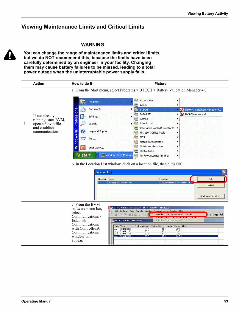
1
If not already running, start BVM, open a *.bvm file and establish communications.
a. From the Start menu, select Programs > BTECH > Battery Validation Manager 4.0
b. In the Location List window, click on a location file, then click OK.
c. From the BVM software menu bar, select Communications>Establish Communications with Controller.A Communications window will appear.
Operating Manual 53
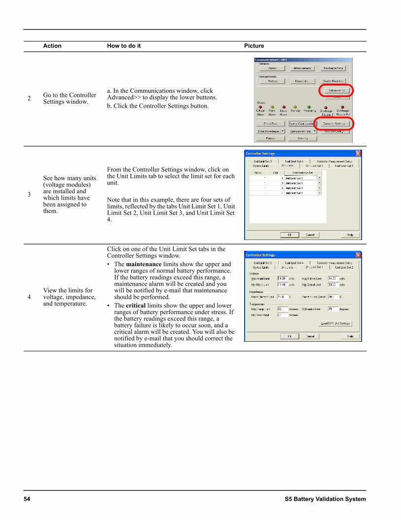
2 Go to the Controller Settings window.
a. In the Communications window, click Advanced>> to display the lower buttons.b. Click the Controller Settings button.
3
See how many units (voltage modules) are installed and which limits have been assigned to them.
From the Controller Settings window, click on the Unit Limits tab to select the limit set for each unit.
Note that in this example, there are four sets of limits, reflected by the tabs Unit Limit Set 1, Unit Limit Set 2, Unit Limit Set 3, and Unit Limit Set 4.
4View the limits for voltage, impedance, and temperature.
Click on one of the Unit Limit Set tabs in the Controller Settings window.• The maintenance limits show the upper and
lower ranges of normal battery performance. If the battery readings exceed this range, a maintenance alarm will be created and you will be notified by e-mail that maintenance should be performed.
• The critical limits show the upper and lower ranges of battery performance under stress. If the battery readings exceed this range, a battery failure is likely to occur soon, and a critical alarm will be created. You will also be notified by e-mail that you should correct the situation immediately.
Action How to do it Picture
54 S5 Battery Validation System
Viewing Battery Activity
Viewing Battery MeasurementsAction How to do it Picture
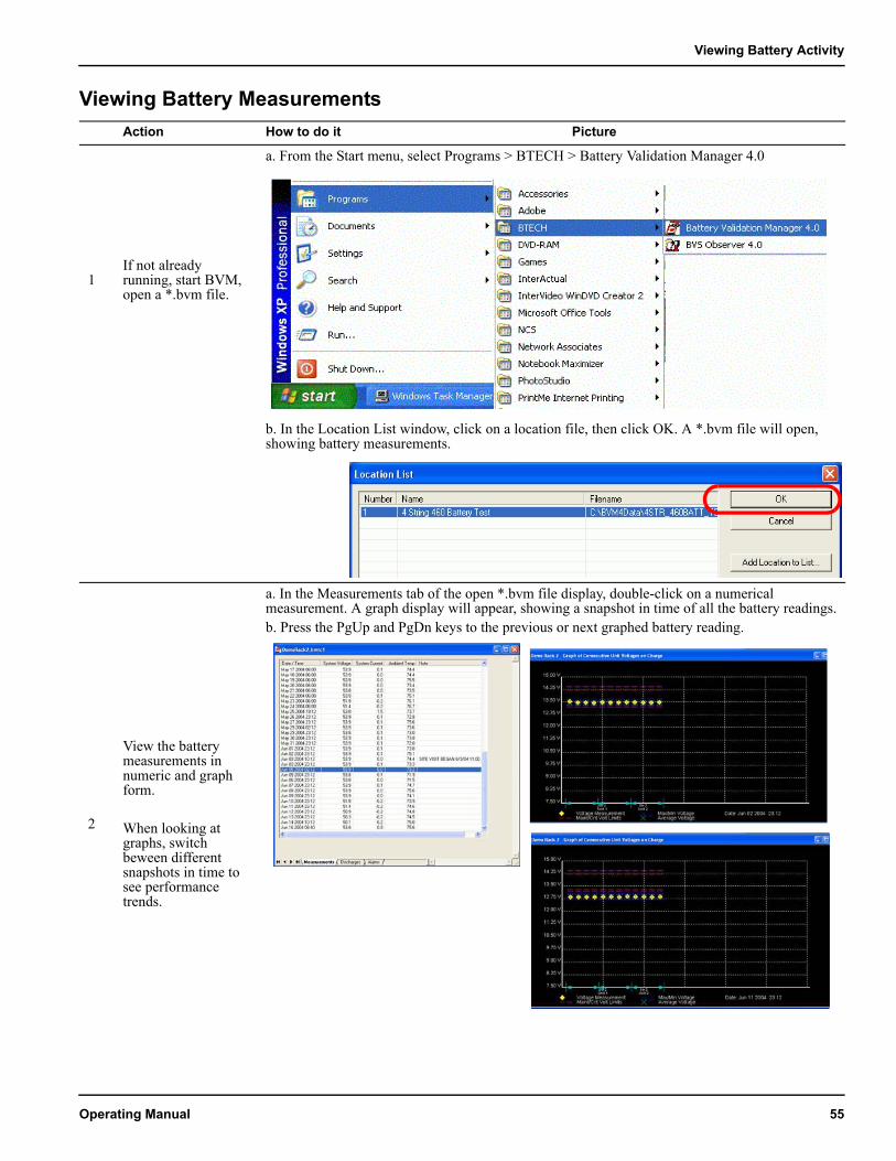
1If not already running, start BVM, open a *.bvm file.
a. From the Start menu, select Programs > BTECH > Battery Validation Manager 4.0
b. In the Location List window, click on a location file, then click OK. A *.bvm file will open, showing battery measurements.
2
View the battery measurements in numeric and graph form.
When looking at graphs, switch beween different snapshots in time to see performance trends.
a. In the Measurements tab of the open *.bvm file display, double-click on a numerical measurement. A graph display will appear, showing a snapshot in time of all the battery readings.b. Press the PgUp and PgDn keys to the previous or next graphed battery reading.
Operating Manual 55
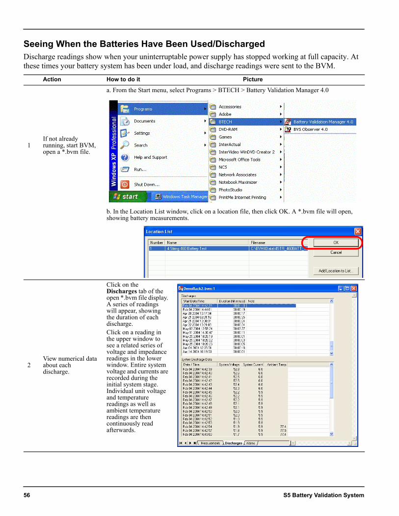
Seeing When the Batteries Have Been Used/DischargedDischarge readings show when your uninterruptable power supply has stopped working at full capacity. At these times your battery system has been under load, and discharge readings were sent to the BVM.
Action How to do it Picture
1If not already running, start BVM, open a *.bvm file.
a. From the Start menu, select Programs > BTECH > Battery Validation Manager 4.0
b. In the Location List window, click on a location file, then click OK. A *.bvm file will open, showing battery measurements.
2View numerical data about each discharge.
Click on the Discharges tab of the open *.bvm file display. A series of readings will appear, showing the duration of each discharge.Click on a reading in the upper window to see a related series of voltage and impedance readings in the lower window. Entire system voltage and currents are recorded during the initial system stage. Individual unit voltage and temperature readings as well as ambient temperature readings are then continuously read afterwards.
56 S5 Battery Validation System
Viewing Battery Activity
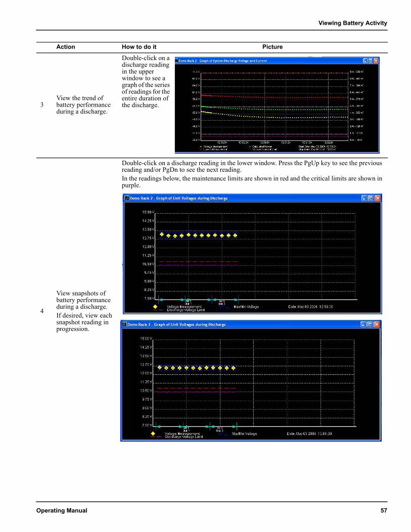
3View the trend of battery performance during a discharge.
Double-click on a discharge reading in the upper window to see a graph of the series of readings for the entire duration of the discharge.
4
View snapshots of battery performance during a discharge. If desired, view each snapshot reading in progression.
Double-click on a discharge reading in the lower window. Press the PgUp key to see the previous reading and/or PgDn to see the next reading.In the readings below, the maintenance limits are shown in red and the critical limits are shown in purple.
Action How to do it Picture
Operating Manual 57

58 S5 Battery Validation System